

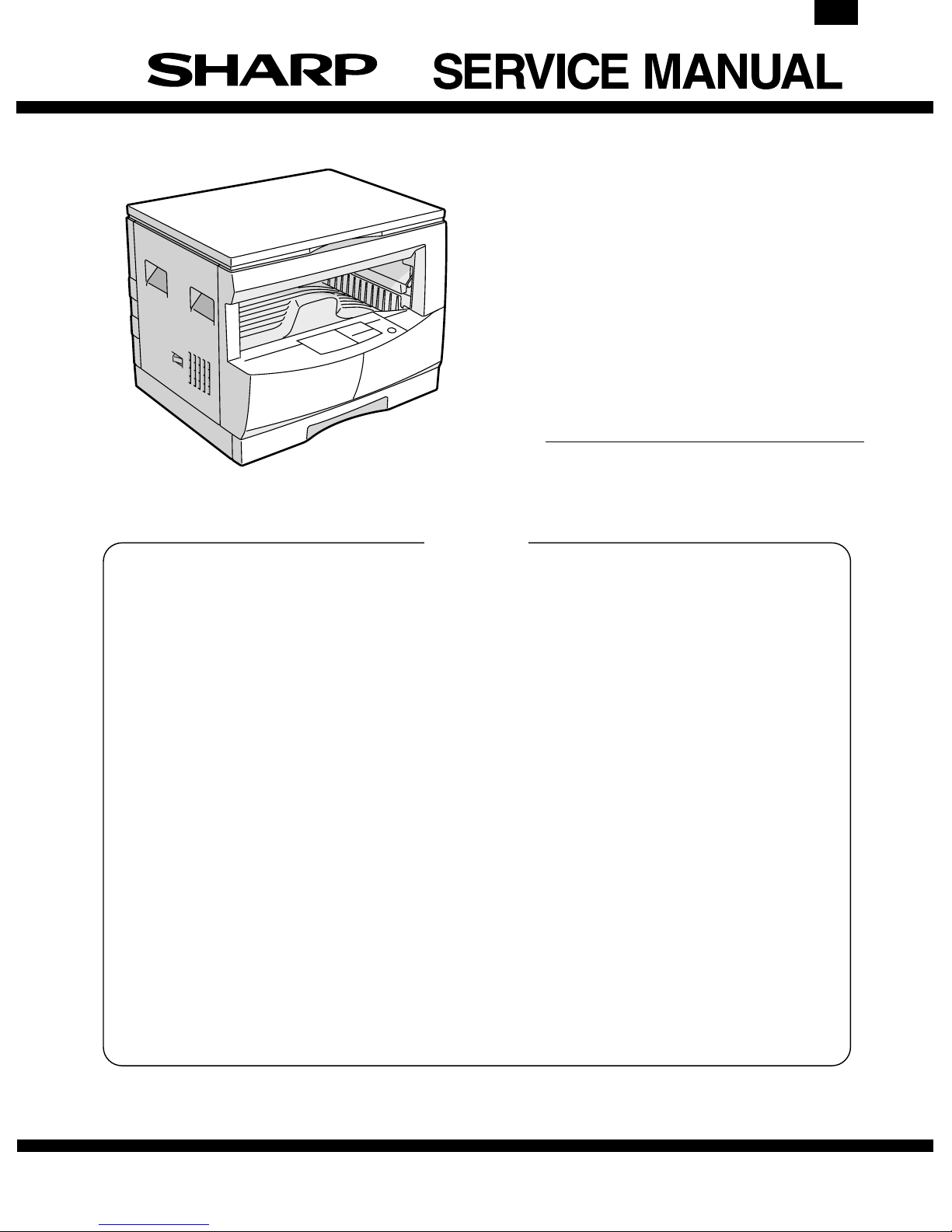
Sharp AL-1600,AL-1610 Service Manual
AL-1610
CODE: 00ZAL1610//A1E
DIGITAL COPIER
AL-1600
MODEL AL-1610
CONTENTS
[ 1 ] GENERAL . . . . . . . . . . . . . . . . . . . . . . . . . . . . . . . . . . . . . . . . . . . . . . . . 1-1
[ 2 ] SPECIFICATIONS . . . . . . . . . . . . . . . . . . . . . . . . . . . . . . . . . . . . . . . . . 2-1
[ 3 ] CONSUMABLE PARTS . . . . . . . . . . . . . . . . . . . . . . . . . . . . . . . . . . . . . 3-1
[ 4 ] EXTERNAL VIEWS AND INTERNAL STRUCTURE . . . . . . . . . . . . . . . 4-1
[ 5 ] UNPACKING AND INSTALLATION . . . . . . . . . . . . . . . . . . . . . . . . . . . . 5-1
[ 6 ] OPERATIONAL DESCRIPTIONS . . . . . . . . . . . . . . . . . . . . . . . . . . . . . 6-1
[ 7 ] ADJUSTMENTS . . . . . . . . . . . . . . . . . . . . . . . . . . . . . . . . . . . . . . . . . . . 7-1
[ 8 ] SIMULATIONS . . . . . . . . . . . . . . . . . . . . . . . . . . . . . . . . . . . . . . . . . . . . 8-1
[ 9 ] USER PROGRAM . . . . . . . . . . . . . . . . . . . . . . . . . . . . . . . . . . . . . . . . . . 9-1
[10] TROUBLE CODE LIST . . . . . . . . . . . . . . . . . . . . . . . . . . . . . . . . . . . . . 10-1
[11] DISASSEMBLY AND ASSEMBLY . . . . . . . . . . . . . . . . . . . . . . . . . . . . 11-1
[12] ELECTRICAL SECTION . . . . . . . . . . . . . . . . . . . . . . . . . . . . . . . . . . . . 12-1
[13] CIRCUIT DIAGRAM . . . . . . . . . . . . . . . . . . . . . . . . . . . . . . . . . . . . . . . 13-1
[14] ACTUAL WIRING DIAGRAM . . . . . . . . . . . . . . . . . . . . . . . . . . . . . . . . 14-1
Parts marked with "!" is important for maintaining the safety of the set. Be sure to replace these parts with specified
ones for maintaining the safty and performance of the set.
SHARP CORPORATION
This document has been published to be used
for after sales service only.
The contents are subject to change without notice.
AL-1610
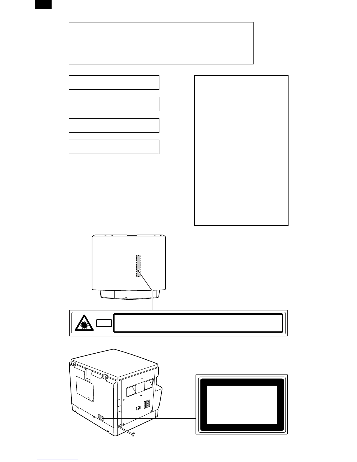
Warning!
This product is a class A product.
If it is operated in households, offices or similar surroundings, it
can produce radio interferences at other appliances, so that the
user has to take adequate countermeasures.
CLASS 1 LASER PRODUCT
LASER KLASSE 1
LUOKAN 1 LASERLAITE
KLASS 1 LASERAPPARAT
VAROITUS!
LAITTEEN KÄYTTÄMINEN
MUULLA KUIN TÄSSÄ
KÄYTTÖOHJEESSA MAINITULLA
TAVALLA SAATTAA ALTISTAA
KÄYTTÄJÄN
TURVALLISUUSLUOKAN 1
YLITTÄVÄLLE
NÄKYMÄTTÖMÄLLE
LASERSÄTEILYLLE.
VARNING
OM APPARATEN ANVÄNDS PÅ
ANNAT SÄTT ÄN I DENNA
BRUKSANVISNING
SPECIFICERATS, KAN
ANVÄNDAREN UTSÄTTAS FÖR
OSYNLIG LASERSTRÅLNING,
SOM ÖVERSKRIDER GRÄNSEN
FÖR LASERKLASS 1.
CAUTION
Laserstrahl
VORSICHT
ADVARSEL
INVISIBLE LASER RADIATION WHEN OPEN AND INTERLOCKS DEFEATED.
AVOID EXPOSURE TO BEAM.
UNSICHTBARE LASERSTRAHLUNG WENN ABDECKUNG GEÖFFNET UND
SICHERHEITSVERRIEGELUNG ÜBERERÜCKT. NICHT DEM STRAHL AUSSETZEN.
USYNLIG LASERSTRÅLING VED ÅBNING, NÅR SIKKERHEDSAFBRYDERE ER
UDE AF FUNKTION. UNDGA UDSAETTELSE FOR STRÅLING.
ADVERSEL
VARNING
VARO!
USYNLIG LASERSTRÅLING NÅR DEKSEL ÅPNES OG SIKKERHEDSLÅS BRYTES.
UNNGÅ EKSPONERING FOR STRÅLEN.
OSYNLIG LASERSTRÅLNING NÄR DENNA DEL ÄR ÖPPNAD OCH SPÄRRAR ÄR
URKOPPLADE. STRÅLEN ÄR FARLIG. BETRAKTA EJ STRÅLEN.
AVATTAESSA JA SUOJALUKITUS OHITETTAESSA OLET ALTTIINA NÄKYMÄTÖNTÄ
LASERSÄTEILYLLE. ÄLÄ KATSO SÄTEESEEN.
CLASS 1
LASER PRODUCT
LASER KLASSE 1

CONTENTS
AL-1610
[ 1 ] GENERAL . . . . . . . . . . . . . . . . . . . . . . . . . . . . . . . 1-1
1. General . . . . . . . . . . . . . . . . . . . . . . . . . . . . . . . 1-1
2. Target user copy volum e: M ont hly average . . . 1-1
3. Main features . . . . . . . . . . . . . . . . . . . . . . . . . . . 1-1
4. Copier installation . . . . . . . . . . . . . . . . . . . . . . . 1-1
[ 2 ] SPECIFICATIONS . . . . . . . . . . . . . . . . . . . . . . . . 2-1
1. Copy mode . . . . . . . . . . . . . . . . . . . . . . . . . . . . 2-1
[ 3 ] CONSUMABLE PARTS . . . . . . . . . . . . . . . . . . . 3-1
1. Supply system table . . . . . . . . . . . . . . . . . . . . . 3-1
2. Environment conditions . . . . . . . . . . . . . . . . . . . 3-2
3. Production number identification . . . . . . . . . . . . 3-2
[ 4 ] EXTERNAL VIEWS AND INTERNAL
STRUCTURE . . . . . . . . . . . . . . . . . . . . . . . . . . . . . 4-1
1. Appearance . . . . . . . . . . . . . . . . . . . . . . . . . . . . 4-1
2. Internal . . . . . . . . . . . . . . . . . . . . . . . . . . . . . . . 4-1
3. Operation Section . . . . . . . . . . . . . . . . . . . . . . . 4-2
4. Motor, solenoid, clutch . . . . . . . . . . . . . . . . . . . 4-3
5. Sensor, switch . . . . . . . . . . . . . . . . . . . . . . . . . . 4-4
6. PWB unit . . . . . . . . . . . . . . . . . . . . . . . . . . . . . . 4-5
7. Cross sect i onal vi ew . . . . . . . . . . . . . . . . . . . . . 4-6
[ 5 ] UNPACKING AND INSTALLATION . . . . . . . . . 5-1
1. Unpaking pr ocedure . . . . . . . . . . . . . . . . . . . . . 5-1
2. Installi ng pr ocedure . . . . . . . . . . . . . . . . . . . . . . 5-1
[ 9 ] USER PROGRAM . . . . . . . . . . . . . . . . . . . . . . . . 9-1
1. User progra m fun ct ions . . . . . . . . . . . . . . . . . . 9-1
2. Setting change procedure . . . . . . . . . . . . . . . . . 9-1
[10] TROUBLE CODE LIST . . . . . . . . . . . . . . . . . . . 10-1
[11] DISASSEMBLY AND ASSEMBLY . . . . . . . . . 11-1
1. High voltag e secti on . . . . . . . . . . . . . . . . . . . . 11-1
2. Optical section . . . . . . . . . . . . . . . . . . . . . . . . 11-1
3. Fusing section . . . . . . . . . . . . . . . . . . . . . . . . . 11-2
4. Paper exit section . . . . . . . . . . . . . . . . . . . . . . 11-4
5. MCU . . . . . . . . . . . . . . . . . . . . . . . . . . . . . . . . 11-6
6. Optical fra m e uni t . . . . . . . . . . . . . . . . . . . . . . 11-6
7. LSU . . . . . . . . . . . . . . . . . . . . . . . . . . . . . . . . . 11-6
8. Tray paper feed sectio n/
Paper transport section . . . . . . . . . . . . . . . . . . 11-7
9. Manual m ul ti paper feed section . . . . . . . . . . . 11-8
10. Power section . . . . . . . . . . . . . . . . . . . . . . . . 11-10
[12] ELECTRICAL SECTION . . . . . . . . . . . . . . . . . . 12-1
1. Outline . . . . . . . . . . . . . . . . . . . . . . . . . . . . . . . 12-1
2. MCU . . . . . . . . . . . . . . . . . . . . . . . . . . . . . . . . 12-2
3. CCD PWB . . . . . . . . . . . . . . . . . . . . . . . . . . . 12-13
[13] CIRCUIT DIAGRAM . . . . . . . . . . . . . . . . . . . . . . 13-1
[14] ACTUAL WIRING DIAGRAM . . . . . . . . . . . . . 14-1
[ 6 ] OPERATIONAL DESCRIPTIONS . . . . . . . . . . . 6-1
1. Outline of oper ation . . . . . . . . . . . . . . . . . . . . . . 6-1
2. Scanner section . . . . . . . . . . . . . . . . . . . . . . . . 6-1
3. Process section . . . . . . . . . . . . . . . . . . . . . . . . . 6-2
4. Laser unit . . . . . . . . . . . . . . . . . . . . . . . . . . . . . . 6-5
5. Paper feed section . . . . . . . . . . . . . . . . . . . . . . 6-6
6. Fusing section . . . . . . . . . . . . . . . . . . . . . . . . . . 6-7
[ 7 ] ADJUSTMENTS . . . . . . . . . . . . . . . . . . . . . . . . . . 7-1
1. Adjustme nt item l ist . . . . . . . . . . . . . . . . . . . . . . 7-1
2. Copier adju st m ent . . . . . . . . . . . . . . . . . . . . . . . 7-1
[ 8 ] SIMULATIONS . . . . . . . . . . . . . . . . . . . . . . . . . . . 8-1
1. Entering t he sim ul at i on m ode . . . . . . . . . . . . . . 8-1
2. Cancellin g the si m ulat io n m ode . . . . . . . . . . . . 8-1
3. List of simulatio ns . . . . . . . . . . . . . . . . . . . . . . . 8-1
4. Contents of simu la tions . . . . . . . . . . . . . . . . . . . 8-2

AL-1610
[1] GENERAL
1. General
This model is a digital personal copier produced with key words of
"Comfort able copy, Clear copy, Easy copy" providing high copy performances and copy productivity.
2. Target User Copy Volume: Monthly
Average
2000~3000 sheets
3. Main features
A. High-speed laser copying
• First-copy time is only 7.4 seconds (normal mode).
• Copying speed is 16 copies/min., which adapts to business use,
allowing improvement of working efficiency.
B. High-quality digital image
• High-quality copying at 600 dpi is performed.
• In addition to the automatic exposure mode, the manual exposure
can be adjusted in five steps.
• The photo mode copying function allows clear copying of delicate
halftone original images such as monochrome photos and color
photos. Photo mode is adjustable in five steps
C. Substantial copying features
• Zoom copying from 50% to 200% in 1% increments can be per-
formed.
• Continuous copying of maximum 99 sheets can also be per-
formed.
• Toner save mode reduces toner consumption by approximately
10%.
• User programs allow setting/modification of functions for customer
needs.
D. Scan once/ Print many (AL-1610 only)
• The copier is equipped with a 1-page memory buffer. This memory
allows the copier to scan an original 1 time only and make up to 99
copies. This feature allows for improved workflow, reduced operating noise from the copier and reduced wear and tear on the scanning mechanism, which provides for a higher reliability.
E. Environmentally friendly design
• Paper output tray is housed in the copier for space saving.
• Preheat mode and auto power shut-off mode are provided to
reduce power consumption in standby mode.
4. Copier installation
Do not install your copier in areas that are:
• damp, humid, or very dusty
• exposed to direct sunlight
• poorly ventilated
• subject to extreme temperature or humidity changes, e.g., near an
air conditioner or heater.
• Be sure to allow the required space around the machine for servic-
ing and proper ventilation.
4" (10 cm)
1 – 1
AL-1610
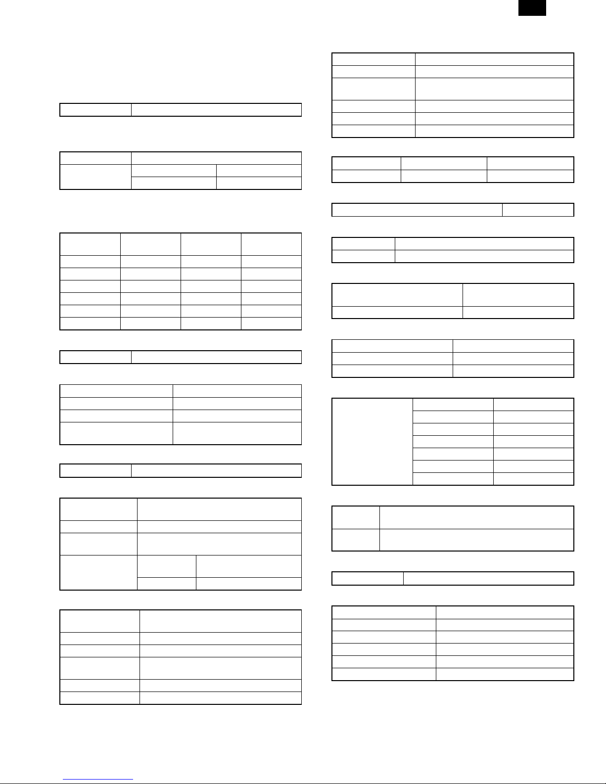
[2] SPECIFICATIONS
1. Copy mode
A. Type
Type Desk-top
B. Copy speed
(1) Basic speed
1 scan 1 copy 16 sheets/min
1 scan multi copy AL-1600 Not available
AL-1610 Available
Condition: Copy speed in the normal copy from all the paper feed
ports including the manual paper feed port.
(2) Continuous copy speed (Sheets/min)
Paper size Normal
11" × 17" 9 9 9
8.5" × 14" 10 10 10
8.5" × 13" 10 10 10
8.5" × 11" 16 16 14
8.5" × 11R" 12 12 12
8.5" × 5.5" 16 16 16
Enlargement
(200%)
C. First copy time
First copy time 7.2sec (11" × 8.5", 1st cassette, with OC)
D. Document
Max. document size 11" × 17"
Document reference position Left side center
Detection (Platen) None
Detection size 11" × 17", 8.5" × 14", 8.5" × 13",
8.5" × 11", 8.5" × 11"R, 8.5" × 5.5"
(1) SPF/R-SPF
Standard/Option Not available
E. Paper feed
Copy size (Max. ∼ Min.) Cassette: (11" × 17" ∼ 8.5" ×
5.5")
Paper feed system 1 cassette + Multi bypass paper feed
Paper feed
capacity
Remaining
quantity detection
(1) Paper feed section of the copier
Paper feed size 11" × 17", 8.5" × 14", 8.5" × 13", 8.5" × 11",
Side front Front 1st step
Paper feed capacity 250 sheets (56 ∼ 80g/m2 equivalent)
Detection Paper empty detection available, size
Weight 56 ∼ 80g/m
Special paper Recycled paper
250 × 1 (Paper feed tray) + 100 (Multi
bypass feed tray)(56 ∼ 80g/m2 equivalent)
Cassette
section
Manual tray Empty detection available
8.5" × 11"R, 8.5" × 5.5"
detection (by key input)
Empty detection available
2
Reduction
(50%)
(2) Manual paper feed section
Paper feed size 11" × 17" ∼ 8.5" × 5.5"
Paper feed capacity 100 sheets
Detection Size detection not available, paper empty
detection available
Weight 56 ∼ 128g/m
Special paper Recycled paper, OHP film, labels
Paper feed Single except for recycled paper
2
(3) Optional paper feed unit
1-step paper feed unit 2-step paper feed unit
Standard/Option Not available Not available
F. Multi copy
Max. number of multi copy 99 sheets
G. Warmup time
Warmup time Approx. 35 sec (Condition: Standard condition)
Pre-heat Available
H. Copy magnification ratio
Fixed magnification ratio 50, 64, 77, 95, 100, 121,
129, 141, 200%
Zooming 50 ∼ 200%
I. Print density
Density mode Auto/Manual/Photo
No. of manual adjustment 5 steps (Manual/Photo)
Toner save mode Set by the user program
J. Print area
Max. print area Max. 428 × 275
11" × 17" 428 × 275
8.5" × 14" 352 × 212
8.5" × 13" 212 × 326
8.5" × 11" 212 × 275
8.5" × 11"R 275 × 212
8.5" × 5.5" 212 × 136
K. Void width
Void area Lead edge 1 ∼ 4mm, rear edge 4mm or less, both
side 4mm or less
Image loss Max. 4mm in total of lead edge and rear edge, max.
4mm in total of right and left edges (Normal copy)
L. Auto duplex
Standard/Option Not installable
M. Paper exit/finishing
Paper exit section capacity Face down 250 sheets
Job separator Job separator not available
Full detection Not available
Finishing Electronic sort board: Not available
Offset function Not available
Staple function Not available
2 – 1
AL-1610
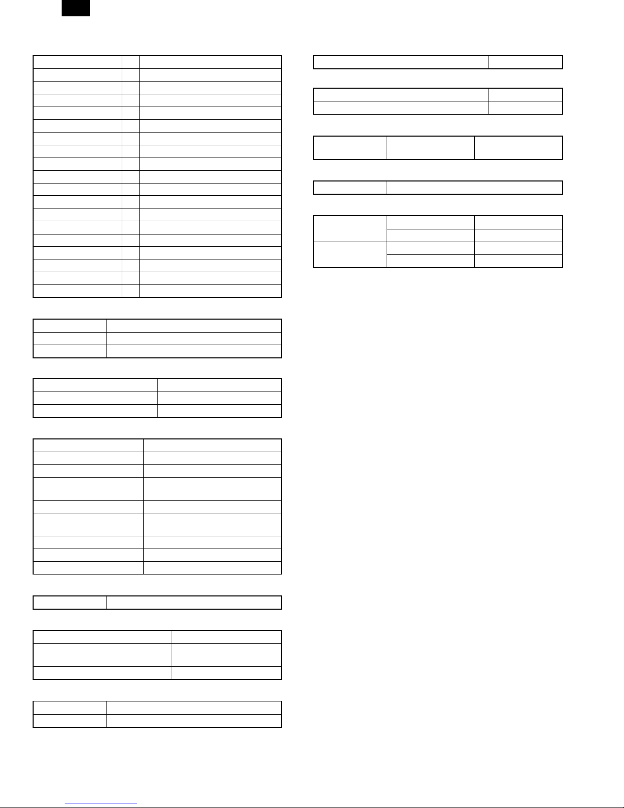
N. Additional functions
APS ✕
AMS ✕
Duplex ✕
Document count ✕
Sorter ✕
Independent zooming ✕
1 set 2 copy ✕
Binding margin ✕
Edge erase ✕
Black-white reversion ✕
2 in 1, 4 in 1 ✕
Rotation copy ✕
Memory copy D AL-1610 only
Pre-heat function F Condition set by the user program
Auto power shut off F Condition set by the user program
Auto tray switching ✕
Message display ✕
User program F
Total counter F
O. Machine composition
Model
AL-1600 16 CPM standard model
AL-1610 16 CPM standard model (With shifter)
(1) Supply parts
Part name
Toner/developer cartridge AL-160-TD-B
Drum cartridge AL-160-DR
T. Power consumption
Max. power consumption About 1.3KWh
* EnergyStar standard (The second level conformity)
Pre-heat About 60Wh
Auto power shut off About 4.8Wh
U. Reliability
Target users Stand-alone copier Monthly average
2,000 ∼ 3,000 copies
V. Noise
Noise BA standard
W. Digital performance
Resolution Reading 400 dpi
Writing 600 dpi
Gradation Reading 256 gradations
Writing Binary
P. Other specifications
Photoconductor type OPC (Organic Photo Conductor)
Photoconductor drum dia. 30mm
Copy lamp Xenon lamp
Developing system Dry 2-component magnetic brush
development
Charging system Saw teeth charging
Transfer system Non-contact (Corona) electrostatic
transfer
Separation system Natural separation
Fusing system Heat roller + Separation pawl
Cleaning system Contact blade
Q. Package form
Body Body/Accessaries
R. External view
External dimensions (W × D × H) 590 × 526 × 467 mm
Occupying area (W × D) 590 × 526mm (When the
manual tray is installed.)
Weight About 34.1kg
S. Power source
Voltage AC120V ±15%
Frequency 50/60Hz common
2 – 2
[3] CONSUMABLE PARTS
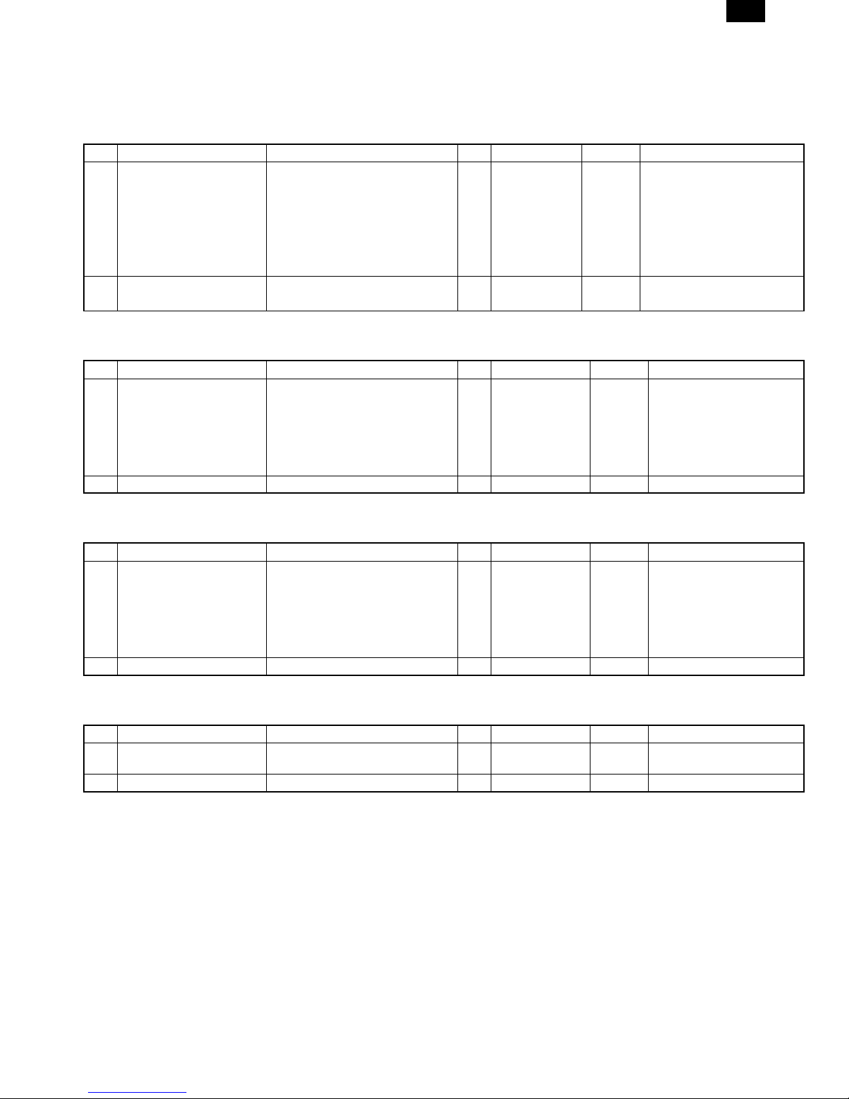
1. Supply system table
A. USA
No. Name Content Life Product name Package Remark
1 Developer cartridge (Black) Toner/developer cartridge
(Toner: 600g, Developer: 400g)
Postcard label
(TLABZ0025YSZZ)
Returned Operation Manual × 1
Vinyl bag × 1
Warranty Card × 1
2 Drum cartridge Drum cartridge × 1 30K AL-160DR 4
Warranty Card × 1
Note: Maintenance parts other than mentioned above must be ordered through the parts department using the proper part number.
B. Canada
No. Name Content Life Product name Package Remark
1 Developer cartridge (Black) Toner/developer cartridge
(Toner: 600g, Developer: 400g)
Postcard label
(TLABZ0025YSZZ)
Returned Operation Manual × 1
Vinyl bag × 1
2 Drum cartridge Drum cartridge × 1 30K AL-160DR 4
Note: Maintenance parts other than mentioned above must be ordered through the parts department using the proper part number.
C. Europe
No. Name Content Life Product name Package Remark
1 Developer cartridge (Black) Toner/developer cartridge
(Toner: 600g, Developer: 400g)
Postcard label
(TLABZ0025YSZZ)
Returned Operation Manual × 1
Vinyl bag × 1
2 Drum cartridge Drum cartridge × 1 30K AL-160DR 4
Note: Maintenance parts other than mentioned above must be ordered through the parts department using the proper part number.
D. Australia, New Zealand, Southeast Asia, LAG, Middle East
No. Name Content Life Product name Package Remark
1 Developer cartridge (Black) Toner/developer cartridge
(Toner: 600g, Developer: 400g)
2 Drum cartridge Drum cartridge × 1 30K AL-160DR 4
Note: Maintenance parts other than mentioned above must be ordered through the parts department using the proper part number.
× 1 15K AL-160TD 4 Life setting by A4 6%
documents
× 1
× 1 15K AL-160TD 4 Life setting by A4 6%
documents
× 1
× 1 15K AL-160TD 4 Life setting by A4 6%
documents
× 1
× 1 15K AL-160TD 4 Life setting by A4 6%
documents
AL-1610
3 – 1
AL-1610
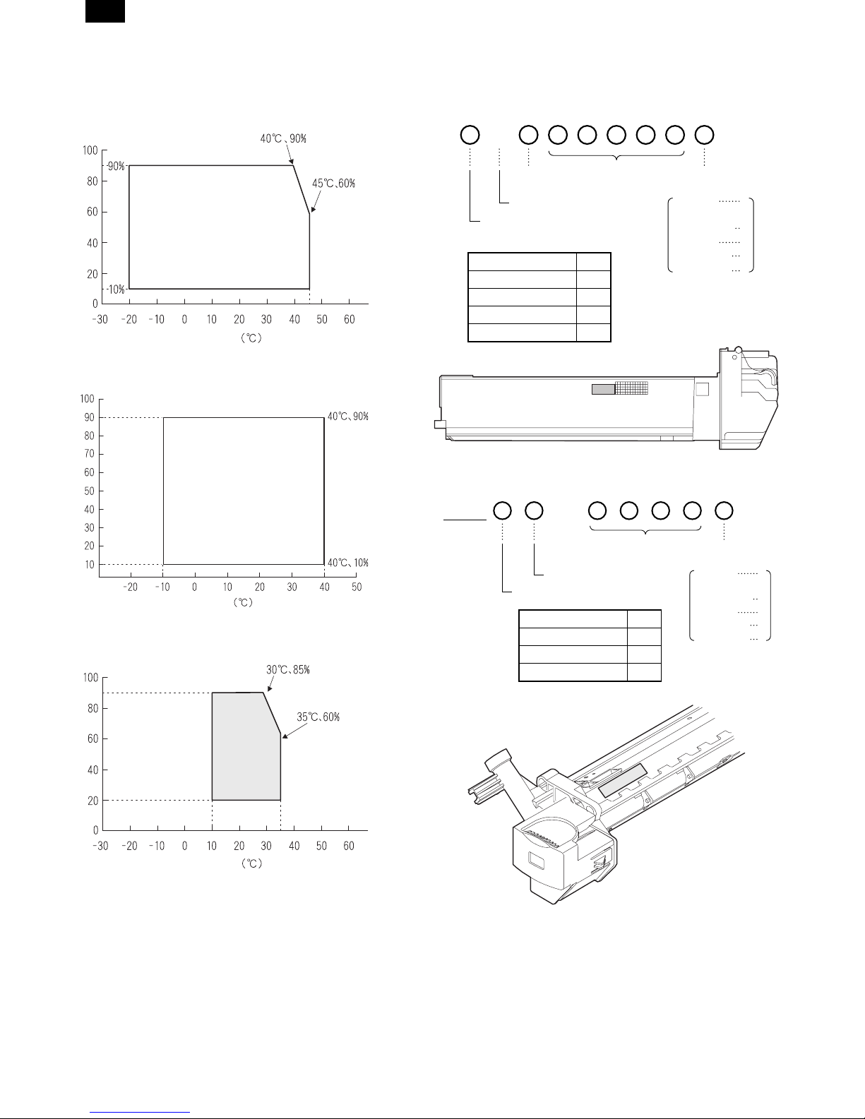
2. Environment conditions
A. Transport condition
(1) Transport conditions
Humidity (%)
Temperature
(2) Storage conditions (packed conditions)
Humidity (%)
3. Production number identification
<Developing cartridge>
The label on the drum cartridge shows the date of production.
B
Destination
(∗)
Indicates production in China.
The end digit of production year
∗: Destination
Division No.
Japan option 1
Ex option 2
Japan, same pack 6
Ex, same pack 7
<Drum cartridge>
The label on the drum cartridge shows the date of production.
Ver. A
Serial number
(00001-99999)
1
Production
month
January
~
September
October
November
December
1
~
9
0
X
Y
Temperature
B. Use conditions
Use environment
conditions
Humidity (%)
Temperature
C. Life (packed conditions)
Photoconductor drum (36 months from the production month)
Developer, toner (24 months from the production month)
Serial number (for each
month) (00001-99999)
Factory
The end digit of production year
Division No.
Ex production 1
Option 2
Same pack 3
Production
month
January
~
September
October
November
December
1
~
9
0
X
Y
3 – 2
[4] EXTERNAL VIEWS AND INTERNAL STRUCTURES
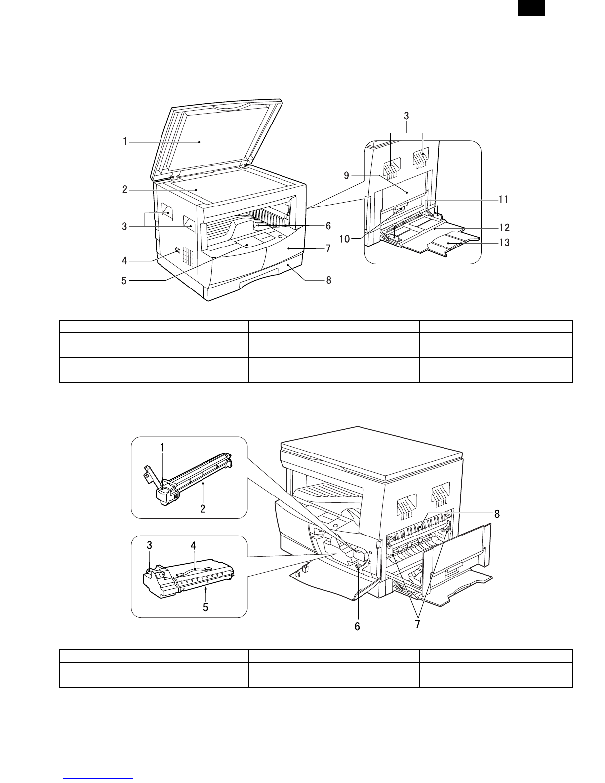
1. Appearance
AL-1610
1 Original cover 2 Original table (OC table) 3 Handles
4 Power switch 5 Operation panel 6 Paper output tray
7 Original size detector 8 Front cover 9 Paper tray
10 Side cover 11 Side cover handle 12 Bypass tray guides
13 Bypass tray
2. Internal
1 Bypass tray extension 2 Drum cartridge handle 3 Drum cartridge
4 TD cartridge handle 5 TD cartridge strap 6 TD cartridge
7 Roller rotating knob 8 Fusing unit release levers 9 Paper guide
4 – 1
AL-1610
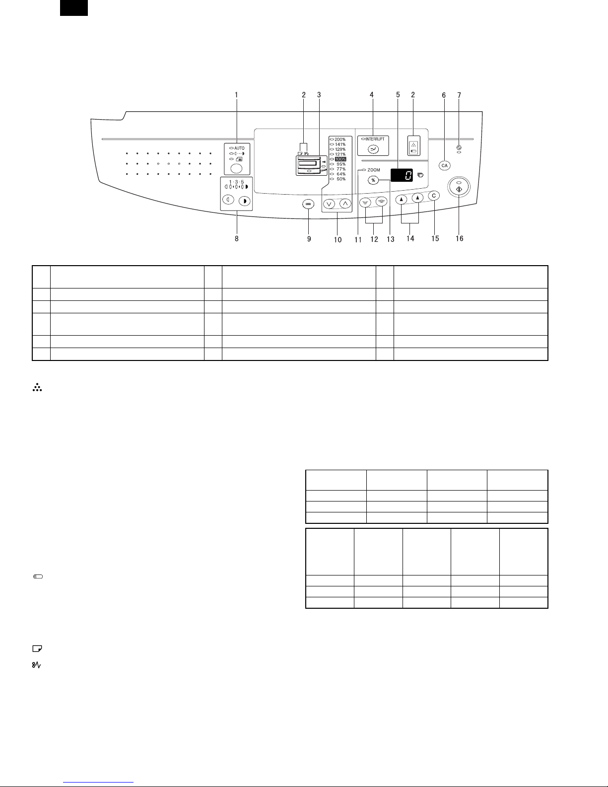
3. Operation Section
1 AUTO/MANUAL/PHOTO key and
indicators
2 Alarm indicators 3 Paper feed location/misfeed location
indicators
4 Interrupt key and indicator 5 Copy quantity display 6 CLEAR ALL key
7 POWER SAVE indicator 8 Light and dark keys and indicators 9 TRAY SELECT key
10 PRESET RATIO selector keys and
11 ZOOM indicator 12 Zoom keys
indicators
13 Copy ratio display key 14 Copy quantity keys 15 CLEAR key
16 START key and indicator
* 1
TD cartridge replacement required indicator
The TD cartridge replacement required indicator will light up
when toner is needed. If copying is continued while the indicator
is lit, copies will gradually become lighter until the copier stops
and the indicator begins blinking. Replace the old TD cartridge
by following the procedure given below.
After the copier stops, it may be possible to make a few more
copies by taking the TD cartridge out of the copier, shaking it
horizontally, then reinstalling it. If copying is not possible after
this operation, replace the TD cartridge. During long copy run of
a dark original, the START key indicator may blink, the indicator
light up, and the copier stop, even though toner is left. The
copier will feed toner for up to 2 minutes and then the START
key indicator will light up. Press the START key to restart copying.
For best copying results, be sure to use only SHARP Genuine
Supplies which are designed, engineered and tested to maximize the life and performance of SHARP copiers. Look for the
Genuine Supplies label on the toner package.
Drum replacement required indicator
The useful life of the drum cartridge is approximately 30,000
copies. When the internal counter reaches approximately 29,000
copies, the drum replacement required indicator will light up in-
* 2
ON: Indicates that the machine is in the energy saving (pre-heat)
mode.
Blink: Indicates that the machine is in the process of resetting from
the energy saving mode or just after supplying the power.
OFF: Indicates that resetting from the energy saving mode is com-
pleted and that the fusing temperature is in ready state.
The combinations of the above display lamps are as follows:
(F = ON. D = OFF)
Lamp
Pre-heat lamp Blink DD
Ready lamp DFD
Other lamps DFF
Lamp
Pre-heat lamp FFBlink Blink
Ready lamp FDFD
Other lamps FDFF
Immediately after
power ON
Energy
saving mode
(Pre-heating)
Energy
saving mode
(Auto power
shut off)
dicating that replacement of the drum cartridge will be needed
soon. When the indicator begins to blink, replace the drum
cartridge by following the procedure given below.
Paper required indicator
Misfeed indicator
Ready Copying
Resetting
from energy
saving mode
Copy is
started during
resetting from
energy
saving mode
4 – 2
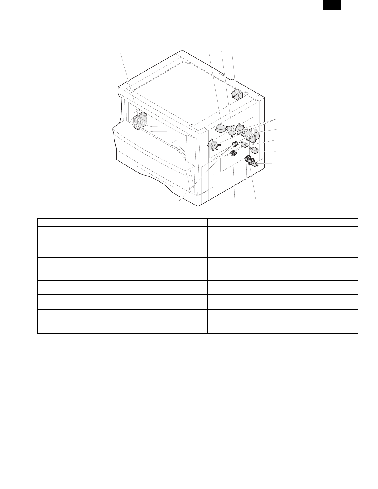
4. Motor, solenoid, clutch
AL-1610
1
23
4
5
6
7
8
9
13
No. Name Code Function, operation
1 Exhaust fan motor VFM Cools the inside of the machine.
2 Shifter motor Shifts the paper exit tray. (AL-1610)
3 Toner motor TM Toner supply
4 Mirror motor MRM Drives the optical mirror base (scanner unit).
5 Cooling fan motor CFM Cools the inside of the machine.
6 Main motor MM Drives the machine.
7 Paper feed solenoid CPFS1 Solenoid for paper feed from cassette
8 Resist roller solenoid RRS Resist roller rotation
Resist roller rotation control solenoid
9 Manual paper feed solenoid MPFS Manual paper feed solenoid
10 Manual paper transport clutch MPTC Drives the manual paper transport roller.
11 Manual paper feed clutch MPFC Drives the manual paper feed roller.
12 Paper feed clutch CPFC1 Drives the cassette paper feed roller.
13 Clutch RRC Drives the resist roller
11 1012
4 – 3

AL-1610
5. Sensor, switch
1234765
8
9
10
11
15
13
12
14
No. Name Code Function, operation
1 Mirror home position sensor MHPS Detects the mirror (scanner unit) home position.
2 Cassette detection switch CSD1 Cassette detection
3 Toner density sensor TCS Toner quantity detection
4 Paper exit sensor (paper exit side) POD1 Detects paper exit.
5 Right door switch DSWR Side door open/close detection
6 Paper full sensor Paper exit tray section full detection <For JOB separator>
7 Lift sensor Paper feed tray lift up detection <For JOB separator>
8 Paper exit sensor (DUP side) POD2 Paper transport detection
9 Thermistor Fusing section temperature detection
10 Thermostat Fusing section abnormally high temperature detection
11 Paper transport sensor PPD Paper transport detection
12 Manual sensor MPED Manual transport detection
13 Cassette paper sensor PED1 Cassette paper empty sensor
14 Drum reset switch DRST New drum detection switch
15 Power switch Turns ON/OFF the main power source.
4 – 4
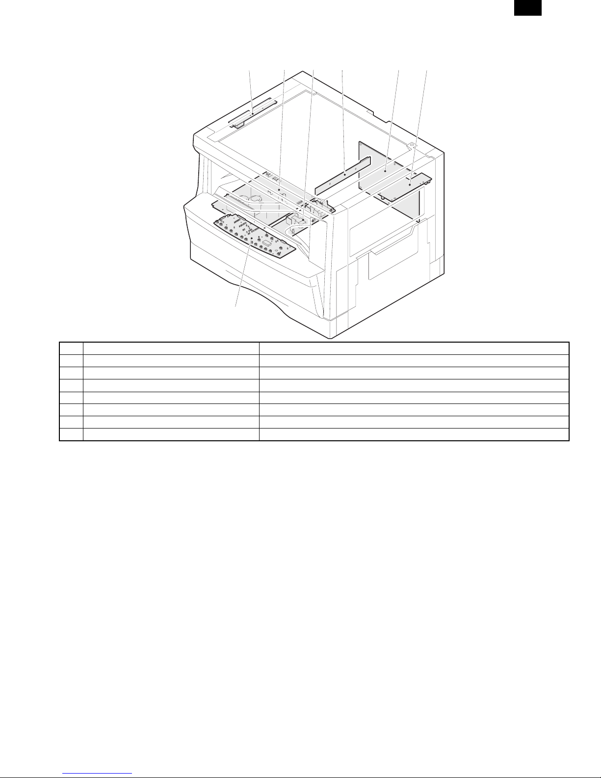
6. PWB unit
AL-1610
1234
6
5
7
No. Name Function, operation
1 Copy lamp invertor PWB Copy lamp control
2 Power PWB AC power input/DC power control
3 High voltage PWB High voltage control
4 CCD sensor PWB Image scanning
5 Main PWB (MCU) Machine control/Image process
6 Paper exit interface PWB Paepr exit, finishing control
7 Operation main PWB Operation panel input/Display, operation panel section control
4 – 5
AL-1610
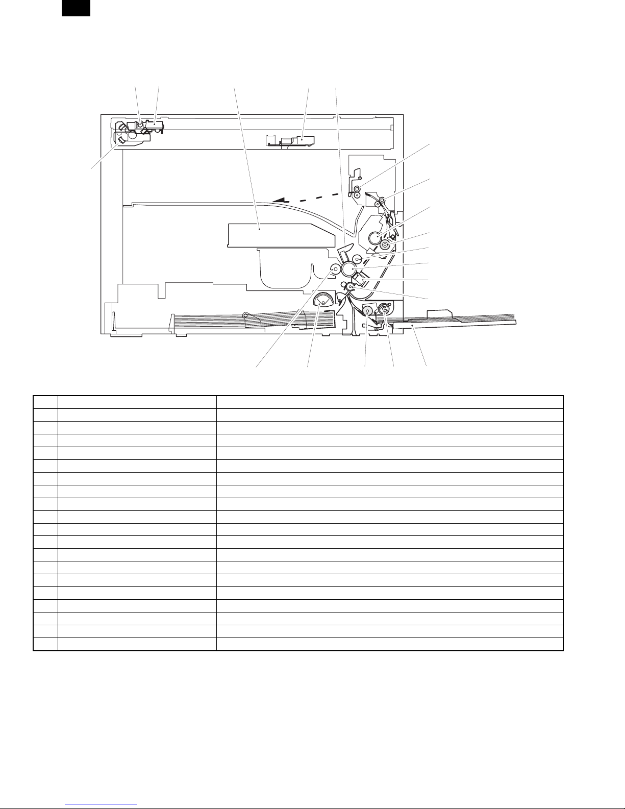
7. Cross sectional view
12 3 45
6
18
7
8
9
19
10
11
12
17
No. Name Function/Operation
1 Copy lamp Image radiation lamp
2 Copy lamp unit Operates in synchronization with No. 2/3 mirror unit to radiate documents sequentially.
3 LSU unit Converts image signals into laser beams to write on the drum.
4 Lens unit Reads images with the lens and the CCD.
5 MC holder unit Supplies negative charges evenly on the drum.
6 Paper exit roller Used to discharge paper.
7 Transport roller Used to transport paper.
8 Upper heat roller Fuses toner on paper (with the teflon roller).
9 Lower heat roller Fuses toner on paper (with the silicon rubber roller).
10 Drum unit Forms images.
11 Transfer charger unit Transfer images (on the drum) onto paper.
12 Resist roller Takes synchronization between the paper lead edge and the image lead edge.
13 Manual paper feed tray Manual paper feed tray
14 Manual paper feed roller Picks up paper in manual paper feed.
15 Manual transport roller Transports paper from the manual paper feed port.
16 Paper feed roller (semi-circular roller) Picks up paper from the cassette.
17 MG roller Puts toner on the OPC drum.
18 No. 2/3 mirror unit Reflects the images from the copy lamp unit to the lens unit.
19 Waste toner transport roller Transports waste toner to the waste toner box.
13141516
4 – 6
AL-1610
[5] UNPACKING AND
INSTALLATION
1. Unpaking procedure
Be sure to hold the handles on both sides of the copier by two
persons to unpack the copier and carry it to the installation location.
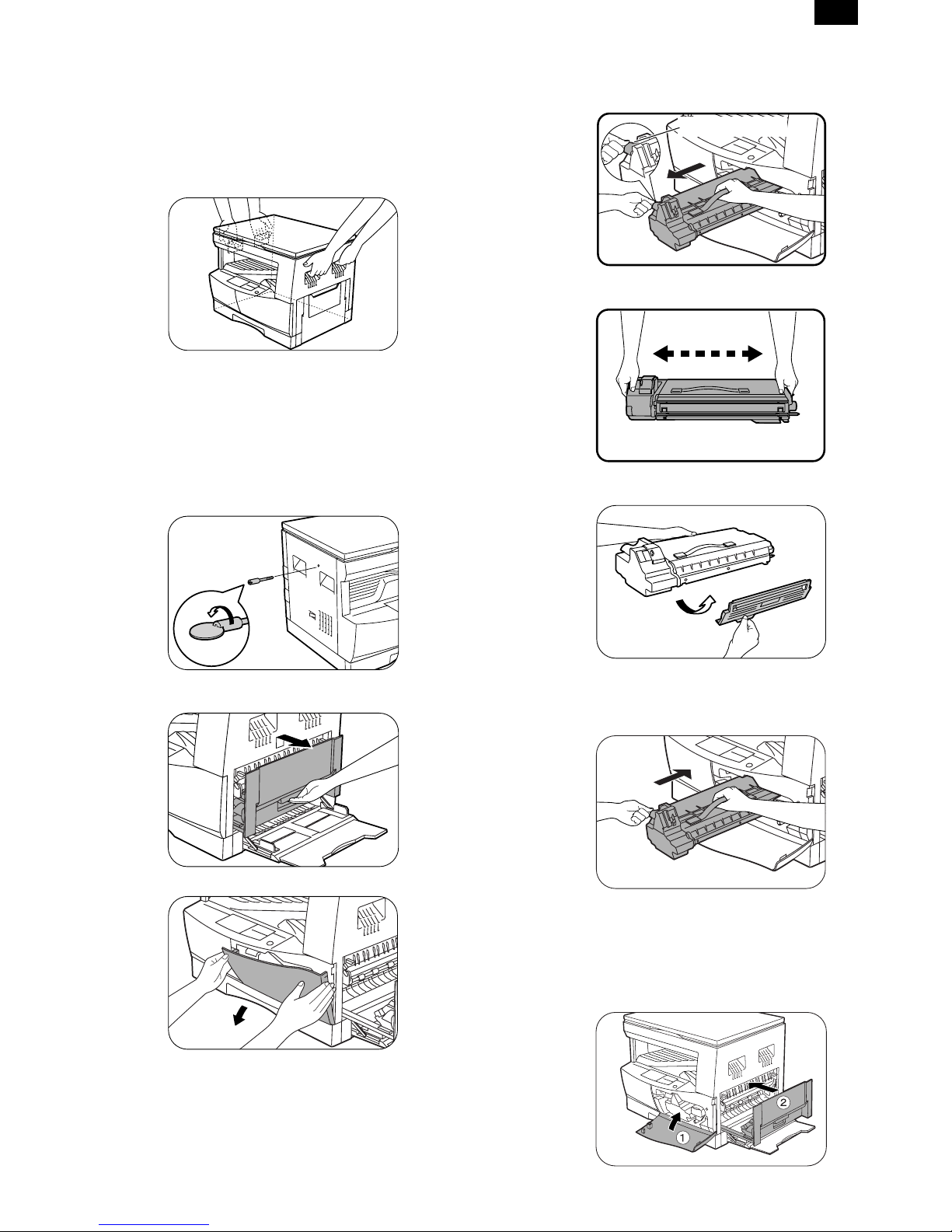
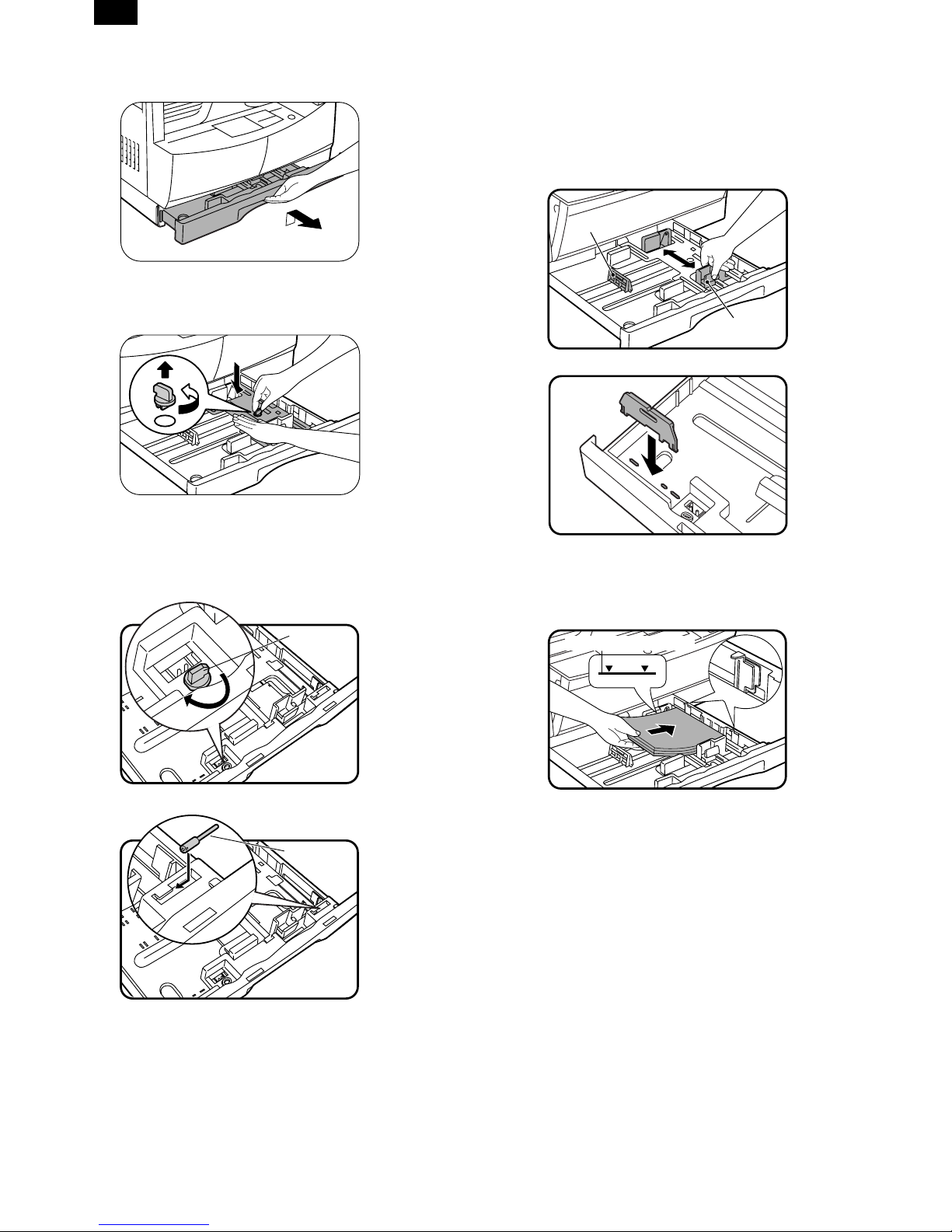
2. Installing procedure
1) Remove all pieces of tape. Then open the original cover and
remove the protective material.
2) Use a coin (or suitable object) to remove the screw.
• Store the screw in the paper tray because it will be used if the
copier has to be moved. (Refer to the description in the following.)
5) Gently pull the TD cartridge out while holding the handle.
6) Hold the strap on the cartridge and remove the TD cartridge upward.
TD cartridge handle
7) Remove the new TD cartridge from the bag. Hold the cartridge on
both sides and shake it horizontally four or five times.
4 or 5 times
8) Hold the tab of the protective cover and pull the tab towards you
to remove the cover.
3) Ensure that the bypass tray is open. Raise the side coverrelease
handle and pull out the side cover until it stops.
4) Push gently on both sides of the front cover to open the cover.
9) Gently insert the TD cartridge along the guides until it locks in
place.
• If dirt or dust is adhered to the TD cartridge, remove it before
installing the cartridge.
10) Close the front cover by holding both sides with your hands and
then close the side cover. The TD cartridge replacement required indicator will go out and the START key indicator will light
up.
• When closing the covers, be sure to close the front cover
securely and then close the side cover. If the covers are
closed in the wrong order, the covers may be damaged.
5 – 1
Front guide
Left guide
Maximum height line
AL-1610
11) Raise the handle of the paper tray and pull the paper tray out
until it stops.
12) Remove the pressure plate lock. Rotate the pressure plate lock
in the direction of the arrow to remove it while pressing down the
pressure plate of the paper tray.
13) Store the pressure plate lock which has been removed in step 5
and the screw which has been removed in step 2 in the front of
the paper tray.
• To store the pressure plate lock, rotate the lock to fix it on the
relevant location.
Pressure
plate
lock
14) Push the pressure plate down until it locks in place.
15) Squeeze the lock lever of the front guide and slide the front
guide to match the width of the paper.
16) Move the left guide to the appropriate slot as marked on the
tray.
• When using 11" × 17" copy paper, store the left guide in the
slot at the left front of the paper tray.
17) Load copy paper into the tray.
• Set the paper along the guides.
• The tray holds up to 250 sheets of about 9kg bond paper.
Do not load paper above the maximum height line.
Screw
18) Push the paper tray firmly back into the copier.
19) Ensure that the power switch of the copier is in the OFF position.
Insert the supplied power cord into the power cord socket at the
rear of the copier.
• If you use the copier in a country other than the country
where the copier was purchased, you will need to make sure
that your local power supply is compatible with your model. If
you plug the copier into an incompatible power supply, irreparable damage to the copier will result.
20) Plug the other end of the power cord into the nearest outlet.
• Only insert the power cord into a properly grounded wall
socket.
Do not use extension cords or power strips.
5 – 2
AL-1610
[6] OPERATIONAL DESCRIPTIONS
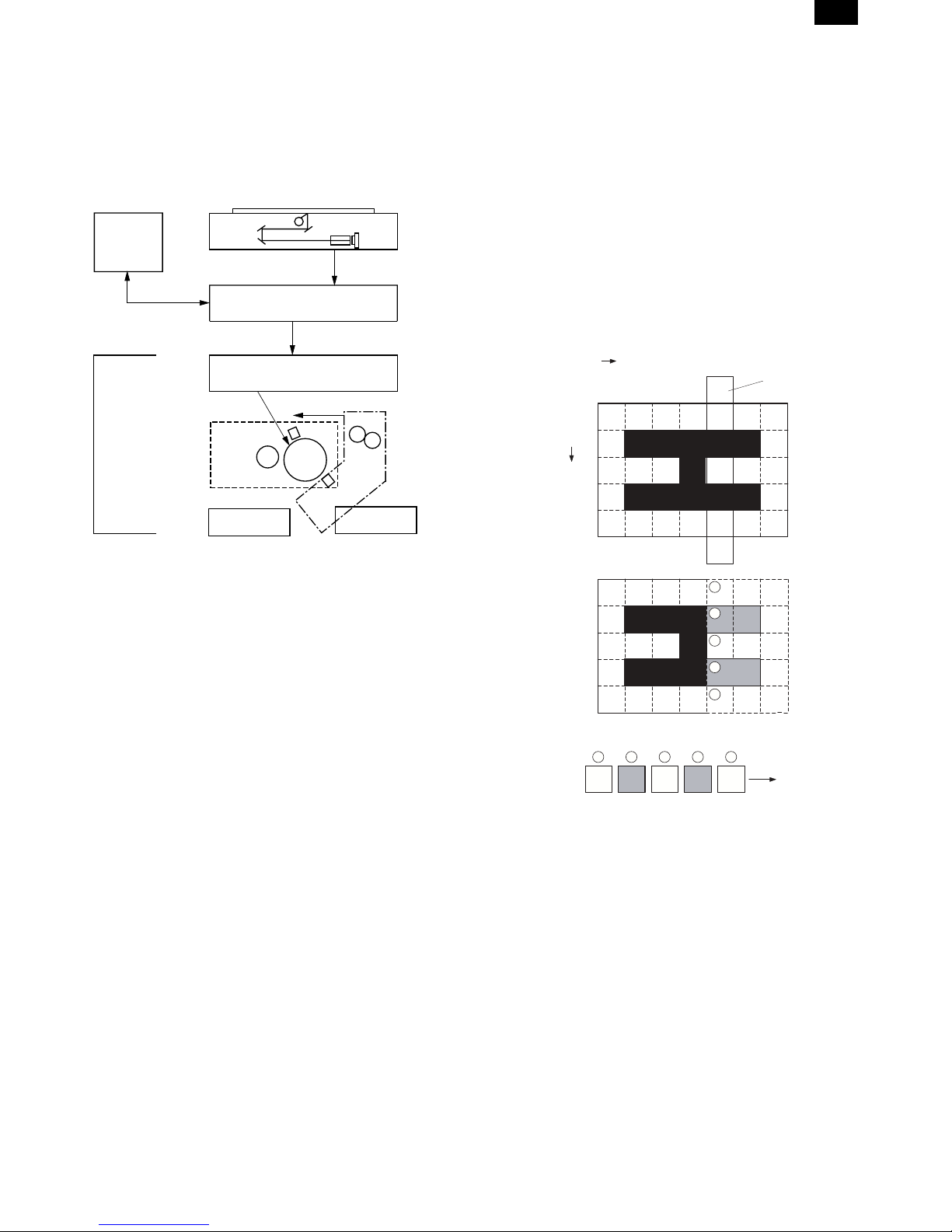
1. Outline of operation
The outline of operation is described referring to the basic configuration.
(Basic configuration)
Operation
section
Printer section
Scanner section
MCU (Main control/image process section)
LSU (Laser unit)
Laser diode, Polygon mirror lens
Laser beam
Process section
Cassette paper
feed section
Paper exit
CCD
Manual paper
feed section
Fusing section
Paper transport section
G. Fusing: Fusing section
• Heat and a pressure are applied to the toner image on the copy
paper to fuse the image on the paper.
2. Scanner section
A. Scan process
The scanner has sensors that are arranged in a line. These sensors
scan a certain area of a document at a time and deliver outputs
sequentially. When the line is finished, the next line is scanned, and
this procedure is repeated. The figure below shows the case where
an image which is scanned is shown with solid lines.
The direction of this line is called main scanning direction, and the
scanning direction sub scanning direction. In the figure above, one
line is divided into 5 sections. Actually, however, one line is divided
into thousands of sections. For scanning, the light receiving element
called CCD is used.
Sub scanning direction
Sensor scanning area
Main
scanning
direction
Outline of copy operation
A. Setting conditions: Operation panel
• Set copy conditions such as the copy quantity and the copy den-
sity with the operation section, and press the START key. The
information on copy conditions is sent to the MCU.
B. Image scanning: Scanner section
• When the START key is pressed, the scanner section starts scan-
ning of images.The light from the copy lamp is reflected by the
document and passed through the lens to the CCD.
C. Photo signal/Electric signal conversion:
Scanner section
• The image is converted into electrical signals by the CCD circuit
and passed to the MCU.
D. Image process: MCU
• The document image signal sent from the CCD circuit is processed
under the revised conditions and sent to the LSU (laser unit) as
print data.
E. Electric signal/Photo signal (laser beam)
conversion: LSU
• The LSU emits laser beams according to the print data. (Electrical
signals are converted into photo signals.)
• The laser beams are radiated through the polygon mirror and
various lenses to the OPC drum.
F. Printing: Process section
• Electrostatic latent images are formed on the OPC drum according
to the laser beams, and the latent images are developed to be
visible images (toner images).
• Meanwhile the paper is fed to the image transfer section in
synchronization with the image lead edge.
• The toner image is transferred on the paper.
1
2
3
4
5
5 4 3 2
1
To MCU PWB
The basic resolution indicates the scanner capacity. The basic resolution is expressed in dpi (dot/inch) which shows the number of light
emitting elements per inch on the document.
The basic resolution of this machine is 400dpi.
In the sub scanning direction, at the same time, the motor that drives
the optical system is controlled to scan the image at the basic resolution.
6 – 1
 Loading...