

Page 1
29F-PS370
1st Edit ion
SERVICE MANUAL
COLOUR TELEVISION
Chassis No. GB-7S
29F-PS370
MODEL
In the interests of user safety (Required by safety regulations in some countries) the set should be restored to its original
condition and only parts indentical to those specified should be used.
World Multi 21System
100-CH Program Memory
AV Mo de (Movie/Music/News)
CATV Hyper Band Ready
White/Blue/Black Stretch Circuit
Picture Noise Reduction
White Temp. Select (5 mode)
Mono Bilingual
Multi Language OSD (English / Thai)
Hotel Mode
Headphone
Gamma Correction
CHAPTER 1. SPECIFICATIONS
[1] SPECIFICATIONS.......................................
CONTENTS
1-1
Off Timer Only
Rear AV-IN 1, AV Output (Monitor Out),
and Front AV-IN 2
Blue Back
Component & Audio Input Terminal
AV Stereo Model
Child Lock
Surround
Loundness
29 Slim CRT
Front AV-2 IN Auto Select
CHAPTER 7. BLOCK DIAGRAM
[1] BLOCK DIAGRAM : MAIN UNIT .................
29F-PS370
7-1
CHAPTER 2. IMPORTANT SERVICE NOTES
[1] IMPORTANT SERVICE NOTE...................
CHAPTER 3. ADJUSTMENT PRECAUTIONS
[1] ADJUSTMENT PRECAUTIONS .................
[2] ADJUSTMENT ............................................
CHAPTER 4. TROUBLE SHOOTING FLOWCHART
[1] TROUBLE SHOOTING FLOWCHART........
CHAPTER 5. SOLID STATE DEVICE BASE DIAGRAM
[1] SOLID STATE DEVICE BASE DIAGRAM...
CHAPTER 6. CHASSIS LAYOUT
[1] CHASSIS LAYOUT......................................
2-1
3-1
3-30
4-1
5-1
6-1
CHAPTER 8. DESCRIPTION OF SCHEMATIC DIAGRAM
[1] DESCRIPTION OF SCHEMATIC DIAGRAM
CHAPTER 9. WAVEFORM
[1] WAVEFORM...............................................
CHAPTER 10. SCHEMATIC DIAGRAM
[1] SCHEMATIC DIAGRAM : MAIN UNIT.........
[2] SCHEMATIC DIAGRAM : CRT UNIT ..........
CHAPTER 11. PRINTED WIRING BOARD ASSEMBLIES
[1] PWB-A : MAIN UNIT....................................
[2] PWB-B : CRT UNIT .....................................
Parts Guide
...
8-1
9-1
10-1
10-2
11-1
11-5
WARNING
The chassis in this receiver is partially hot. Use an isolation transformer between the line cord plug and
power receptacle, when servicing this chassis. To prevent electric shock, do not remove cover. No user serviceable parts inside. Refer servicing to qualified service personnel.
SHARP MANUFACTURING (THAILAND) CO.,LTD
Page 2

29F-PS370
TV29S-FX10MService Manual29S-FX10MMarketE
CHAPTER 1.
SPECIFICATIONS
[1] SPECIFICATIONS
SPECIFICATIONS
Convergence ............................................................................... Self Convergence System
Focus ..................................................................... Bi-Potential, Uni-Potential Electrostatic
Sweep Deflection ................................................................................................... Magnetic
Intermediate Frequencies
Picture IF Carrier ................................................................................................ 38.9MHz
Sound IF Carrier
6.5MHz ............................................................................................................ 32.4MHz
6.0MHz ............................................................................................................ 32.9MHz
5.74MHz ........................................................................................................ 33.16MHz
5.5MHz ............................................................................................................ 33.4MHz
4.5MHz ............................................................................................................ 34.4MHz
Colour Sub-Carrier
PAL ................................................................................................................ 34.47MHz
SECAM .............................................................................................. 34.494/34.65MHz
NTSC ............................................................................................................. 35.32MHz
Power Input ................................................................................... 110 ~ 240V AC 50/60 Hz
Power Consumption ..................................................................................................... 116W
Audio Power Output Rating ......................................................10 w ( R M S ) x 2 (TTL 20W)
Speaker
Size ........................................................................................... 6 cm x 13 cm (square) x 2
Aerial Input Impedance
VHF/UHF ......................................................................................... 75 ohms Unbalanced
Receiving Channels
PAL-B/G ; SECAM-B/G
VHF ................................................................................................................ E2 thru E12
UHF .............................................................................................................. E21 thru E69
CATV ......................................................................................... X thru Z + 2, S1 thru S41
PAL-D/K, SECAM-D/K, K1
VHF .......................................................................................... R1 thru R12, C1 thru C12
UHF .......................................................................................... 21 thru 69, C21 thru C57
PAL-I, SECAM-I
VHF .................................................................................. (IRELAND): B thru J
UHF .................................................................................. (U.K., H.K.): 21 thru 69
NTSC-M
VHF ....................................................................... (U.S.) : 2 thru 13, (JAPAN) : 1 thru 12
UHF ................................................................... (U.S.) : 14 thru 69, (JAPAN) : 13 thru 62
CATV .................................... (U.S.) : A-6 thru A-1, A thru W+29 (JAPAN) : C13 thru C63
Receiving Frequency ................................................................ 44.25 MHz thru 863.25 MHz
Dimensions ..................................................................................................... Width: 764 mm
Height: 613 mm
Depth: 430 mm
Weight(approx): 38.5 kg
Cabinet material .................................................................................................. All Plastics
Specifications are subject to change without prior notice.
1 - 1
Page 3

29F-PS370
TV29S-FX10MService Manual29S-FX10MMarketE
CHAPTER 2.
IMPORTANT SERVICE NOTES
[1] IMPORTANT SERVICE NOTE
IMPORTANT SERVICE NOTES
Maintenance and repairing of this receiver should be done by
qualified service personnel only.
SERVICE OF HIGH VOLTAGE SYSTEM AND
PICTURE TUBE
When servicing the high voltage system, remove static charge from it by
connecting a 10K ohm resistor in series with an insulated wire (such as a test
probe) between picture tube dag and 2nd anode lead. (AC line cord should
be disconnected from AC outlet.)
1. Picture tube in this receiver employs integral implosion protection.
2. Replace with the same type number of picture tube for continued safety.
3. Do not lift picture tube by the neck.
4. Handle the picture tube only when wearing shatterproof goggles and after discharging
the high voltage completely.
X-RAY
This receiver is designed so that any X-Ray radiation is kept to an absolute
minimum. Since certain malfunctions or servicing may produce potentially
hazardous radiation with prolonged exposure at close range, the following
precautions should be observed:
1. When repairing the circuit, please make sure do not increase the high voltage of the set
to more then 30kV (at beam 0 A).
2. To keep the set in a normal operation, please make sure it's function at 26.0kV 1.5kV
(at beam 1700 A). The set has been factory - adjusted to the above-mentioned high voltage.
*If there is a possibility that the high voltage fluctuates as a result of the repaires,
never forget to check for such high voltage after the work.
3. Do not substitute a picture tube with unauthorized types and/or brands which may cause
excessive X-ray radiation.
BEFORE RETURNING THE RECEIVER
Before returning the receiver to the user, perform the following safety checks.
1. Inspect all lead dress to make certain that leads are not pinched or that hardware is not
lodged between the chassis and other metal parts in the receiver.
2. Inspect all protective devices such as non-metal control knobs, insulating fishpapers,
cabinet backs, adjustment and compartment covers or shields, isolation resistor- capacity networks, mechanical insulators etc.
2 - 1
Page 4

29F-PS370
TV29S-FX10MService Manual29S-FX10MMarketE
CHAPTER 3.
[1] ADJUSTMENT PRECAUTIONS
This model's setting are adjusted in two different ways: through the I2C bus control and in the
conventional analog manner. The adjustments via the I2C bus control include preset-only items and
variable data.
1. Setting the service mode by the microprocessor.
ADJUSTMENT PRECAUTIONS
ADJUSTMENT PRECAUTIONS
(1). Press and hold the local key "VOL DOWN" & "CH UP" when power on the main switch,
TV will enter into SERVICE MODE. (The initial values of EEPROM are automatically
preset when new EEPROM is used.)
(2). Press the CH DOWN / UP key on the remote controller to select the setting items
one by one.
(3). Using the VOLUME UP/DOWN key on the remote controller, the data can be modified.
(4). When press the local key "VOL DOWN" & "CH UP" at the same time, it will be released
from the service mode.
2. Factory Presetting.
(1). Press remote controller key of code "ED" for 4 seconds, the initial values are
automatically preset.
(2). The initial data are preset as listed in page 3 - 4 , 3 - 5 and 3 - 6.
(3). Make sure whether the data need to modify or not (Initial data).
Note: Once the chassis has been assembly together and in ready condition, please make
sure it's go through initialize process (see sect 2 above)
Precaution: If haven't done this initialization, malfunction might be happen.
3 - 1
Page 5
29F-PS370
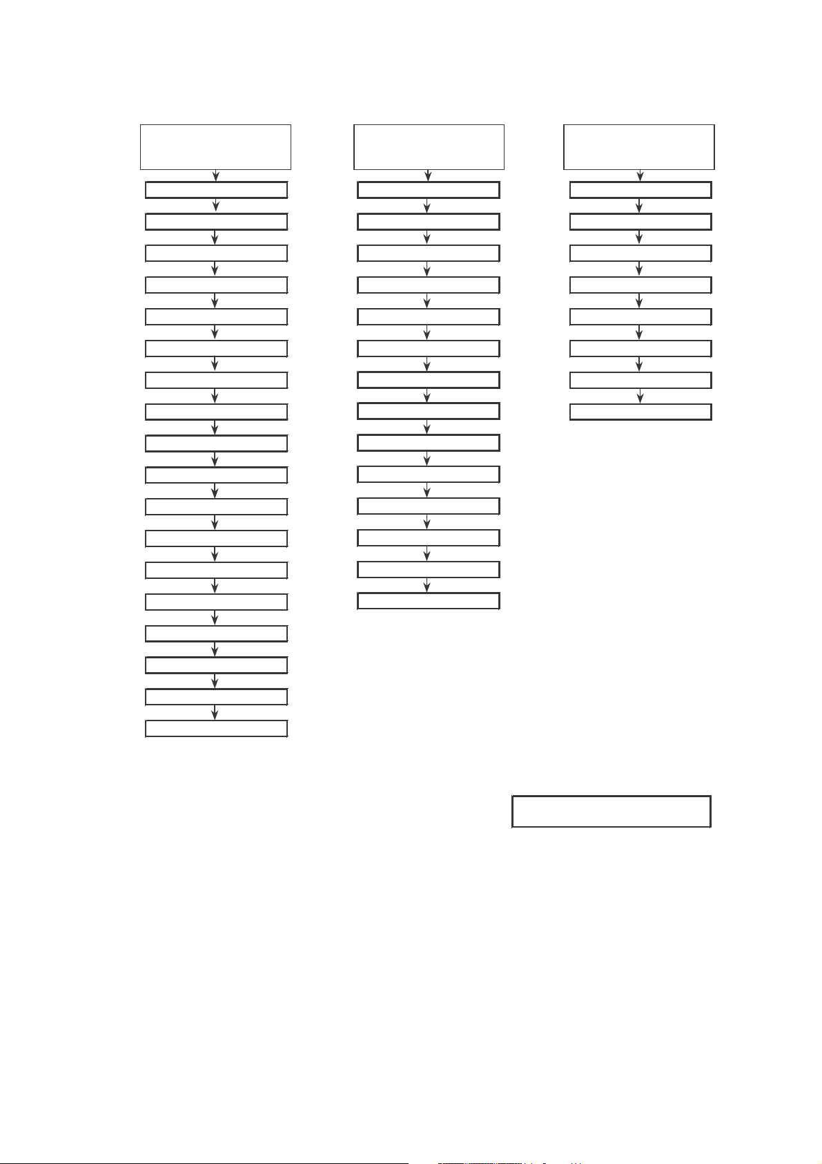
1) In the Service Mode, key is use to select the mode in the following order.
ADJUSTMENT MODE
50Hz/60Hz
RF AGC
GEOMETRIC ADJ
PICTURE/SOUND
SUB ADJ
CUT OFF/
WHITE BALANCE ADJ
3 - 2
Page 6
29F-PS370
ADJUSTMENT MODE ITEMS SEQUENCE
GEOMETRIC
ADJ MODE
VSLOPE
V-SHI-50
V-AMP-50
V-LIN
S-COR
H-SHI-50
EW-W-50
E/W-PAR-50
UPCOR-PAR
LOCOR-PAR
H-BOW
H-PAR
WHITE POINT
ADJ MODE
DRI-RS
DRI-GS
DRI-BS
CUT-RS
CUT-GS
CUT-BS
DRI-RC
DRI-RS-DVD
DRI-GS-DVD
DRI-BS-DVD
CUT-RS-DVD
CUT-GS-DVD
PICTURE SUB ADJ
MODE
SUB-BRI
SUB-BRI-DVD
SUB-COL
SUB-CON
SUB-CON-DVD
SUB-TINT-DVD
SUB-TINT
SUB-SHARP
E/W-TRAP
V-SHI-60
V-AMP-60
H-SHI-60
EW-W-60
E/W-PAR-60
CUT-BS-DVD
DRI-RC-DVD
Notes:
FORWARD : CH UP KEY
REVERSE : CH DOWN KEY
3 - 3
Page 7

29F-PS370
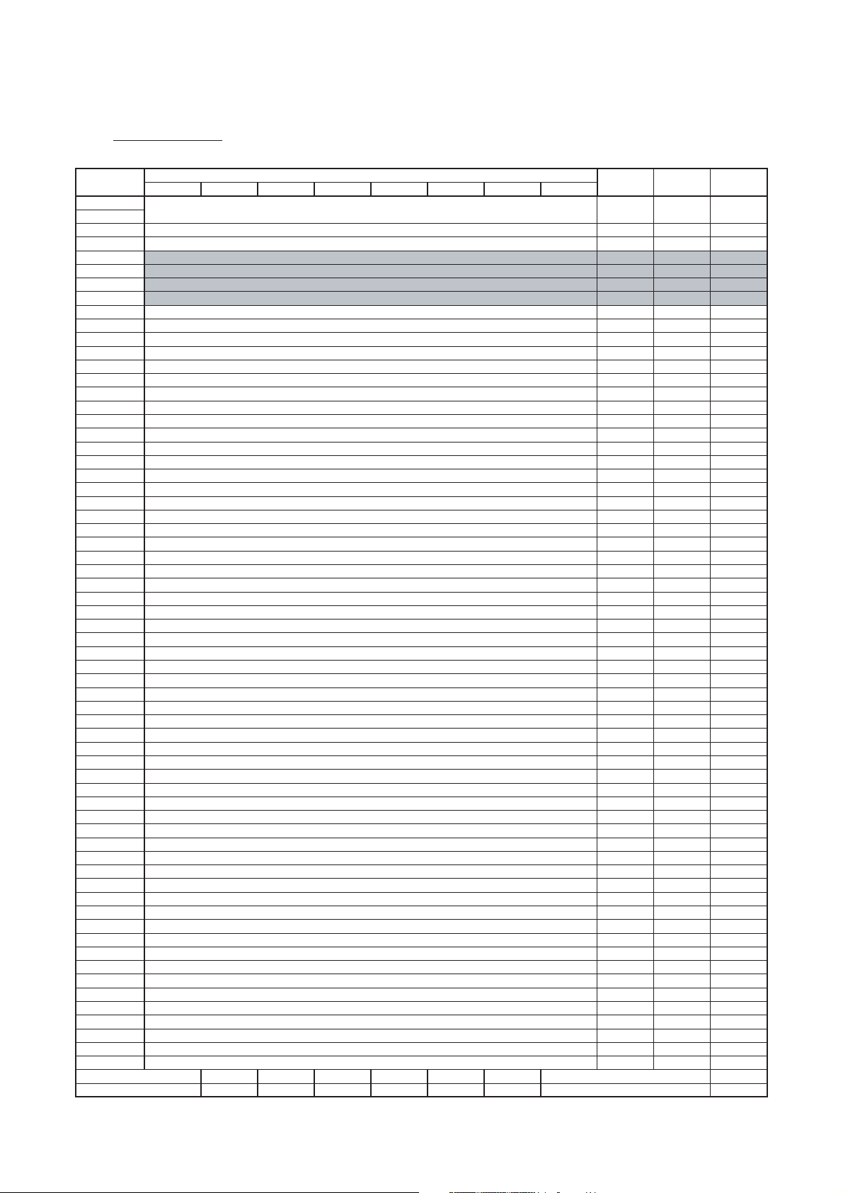
ADJUSTMENT MODE ITEM
ITEM EEPROM SETTING DATA RANGE IC
01 RF-AGC 0…63 UOC-TV
02 V SLOPE 0…63 UOC-TV
03 V-SHI-50 0…63 UOC-TV
04 V-AMP-50 0…63 UOC-TV
05 H-SHI-50 0…63 UOC-TV
06 EW-W-50 0…63 UOC-TV
07 36
08 H-PAR 0…63 UOC-TV
09 H-BOW 0…63 UOC-TV H-BOW 30
10 UPCOR-PAR 0…63 UOC-TV UPCOR-PAR 42
11 LOCOR-PAR 0…63 UOC-TV LOCOR-PAR 44
12 E/W-TRAP 0…63 UOC-TV E/W-TRAP 30
13 V-LIN 0…63 UOC-TV V-LIN 28
14 S-COR 0…63 UOC-TV S-COR 32
15 DRI-RSDRI-RS 0…63 UOC-TV
16 DRI-GS 0…63 UOC-TV DRI-GS 32
E/W-PAR-50 0…63 UOC-TV E/W-PAR-50
OSD DEFAULT
RF-AGC 23
VSLOPE 31
V-SHI-50 36
V-AMP-50 20
H-SHI-50 30
EW-W-50
H-PAR 30
28
32
SET UP (DEC)
ADJ
ADJ
ADJ
ADJ
ADJ
ADJ
ADJ
ADJ
ADJ
ADJ
ADJ
ADJ
ADJ
ADJ
ADJ
ADJ
17 DRI-BS 0…63 UOC-TV DRI-BS 32
18 CUT-RS 0…63 UOC-TV CUT-RS 32
19 CUT-GS 0…63 UOC-TV CUT-GS 32
20 CUT-BS 0…63 UOC-TV CUT-BS 32
21 SUB-BRI 0…63 UOC-TV SUB-BRI 24
22 SUB-CON 0…63 UOC-TV SUB-CON 59
23 SUB-COL 0…63 UOC-TV SUB-COL 10
24 SUB-TINT 0…63 UOC-TV SUB-TINT 36
25 SUB-SHARP 0…63 UOC-TV SUB-SHARP 32
26 DRI-RW 0…63 UOC-TV DRI-RW 32
27 DRI-GW 0…63 UOC-TV DRI-GW 32
28 DRI-BW 0…63 UOC-TV DRI-BW 32
29 CUT-RW 0…63 UOC-TV CUT-RW 32
30 CUT-GW 0…63 UOC-TV CUT-GW 32
31 DRI-RLW 0…63 UOC-TV DRI-RLW 32
32 DRI-GLW 0…63 UOC-TV DRI-GLW 32
33 DRI-BLW 0…63 UOC-TV DRI-BLW 32
ADJ
ADJ
ADJ
ADJ
ADJ
ADJ
ADJ
ADJ
ADJ
ADJ
ADJ
ADJ
ADJ
ADJ
ADJ
ADJ
ADJ
34 CUT-RLW 0…63 UOC-TV CUT-RLW 32
35 CUT-GLW 0…63 UOC-TV CUT-GLW 32
3 - 4
ADJ
ADJ
Page 8

29F-PS370
ITEM EEPROM SETTING DATA RANGE
36 DRI-RC 0…63 UOC-TV DRI-RC 32
37 DRI-GC 0…63 UOC-TV
38 DRI-BC 0…63 UOC-TV DRI-BC 32
39 CUT-RC 0…63 UOC-TV CUT-RC 32
40 CUT-GC 0…63 UOC-TV CUT-GC 32
41 DRI-RLC 0…63 UOC-TV DRI-RLC 32
42 DRI-GLC 0…63 UOC-TV DRI-GLC 32
43 DRI-BLC 0…63 UOC-TV DRI-BLC 32
44 CUT-RLC 0…63 UOC-TV CUT-RLC 32
45 CUT-GLC 0…63 UOC-TV CUT-GLC 32
46 DRI-RS-DVD 0…63 UOC-TV DRI-RS-DVD 32
47 DRI-GS-DVD 0…63 UOC-TV DRI-GS-DVD 32
48 DRI-BS-DVD 0…63 UOC-TV DRI-BS-DVD 32
IC
DRI-GC 32
SETTING DATAOSD DEFAULT
ADJ
ADJ
ADJ
ADJ
ADJ
ADJ
ADJ
ADJ
ADJ
ADJ
ADJ
ADJ
ADJ
49 CUT-RS-DVD 0…63 UOC-TV CUT-RS-DVD 32
50 CUT-GS-DVD 0…63 UOC-TV CUT-GS-DVD 32
51 CUT-BS-DVD 0…63 UOC-TV CUT-BS-DVD 32
52 SUB-BRI-DVD 0…63 UOC-TV SUB-BRI--DVD 24
53 SUB-CON-DVD 0…63 UOC-TV SUB-CON-DVD 48
54 DRI-RW-DVD 0…63 UOC-TV DRI-RW-DVD 32
55 DRI-GW-DVD 0…63 UOC-TV DRI-GW-DVD 32
56 DRI-BW-DVD 0…63 UOC-TV DRI-BW-DVD 32
57 CUT-RW-DVD 0…63 UOC-TV CUT-RW-DVD 32
58 CUT-GW-DVD 0…63 UOC-TV CUT-GW-DVD 32
59 DRI-RLW-DVD UOC-TV DRI-RLW-DVD 32
60 DRI-GLW-DVD 0…63 UOC-TV DRI-GLW-DVD 32
62 CUT-RLW-DVD UOC-TV CUT-RLW-DVD 32
0…63
0…63
0…63
UOC-TV DRI-RLW-DVD61 DRI-BLW-DVD
32
ADJ
ADJ
ADJ
ADJ
ADJ
ADJ
ADJ
ADJ
ADJ
ADJ
ADJ
ADJ
ADJ
ADJ
3 - 5
CUT-GLW-DVD 3263 CUT-GLW-DVD 0…63 UOC-TV
DRI-RC-DVD 3264 DRI-RC-DVD 0…63 UOC-TV
ADJ
ADJ
Page 9

29F-PS370
ITEM EEPROM SETTING DATA RANGE
65 DRI-GC-DVD 0…63 UOC-TV DRI-GC-DVD 32
66 DRI-BC-DVD 0…63 UOC-TV
67 CUT-RC-DVD 0…63 UOC-TV CUT-RC-DVD 32
68 CUT-GC-DVD 0…63 UOC-TV CUT-GC-DVD 32
69 DRI-RLC-DVD 0…63 UOC-TV DRI-RLC-DVD 32
70 DRI-GLC-DVD 0…63 UOC-TV DRI-GLC-DVD 32
71 DRI-BLC-DVD 0…63 UOC-TV DRI-BLC-DVD 32
72 CUT-RLC-DVD 0…63 UOC-TV CUT-RLC-DVD 32
73 CUT-GLC-DVD 0…63 UOC-TV CUT-GLC-DVD 32
74 V-SHI-60 0…63 UOC-TV V-SHI-60 36
75 V-AMP-60 0…63 UOC-TV V-AMP-60 23
76 H-SHI-60 0…63 UOC-TV H-SHI-60 37
77 EW-W-60 0…63 UOC-TV EW-W-60 28
IC
DRI-BC-DVD 32
SETTING DATAOSD DEFAULT
ADJ
ADJ
ADJ
ADJ
ADJ
ADJ
ADJ
ADJ
ADJ
ADJ
ADJ
ADJ
ADJ
78 E/W-PAR-60 0…63 UOC-TV E/W-PAR-60 38
79 VSD 0/1 UOC-TV VSD 0
80 CUT OFF 0-3 UOC-TV CUT OFF 02
81 DCXO 0-255 UOC-TV DCXO 55
82 ISP MODE 0/1 UOC-TV ISP-MODE 0
83 SUB-VOL 0-60 UOC-TV SUB-VOL 55
ADJ
0
02
55
0
55
3 - 6
Page 10
29F-PS370
NVM MAP ITEMS
ADDRESS
(HEX)
0000
0001
0002
0003
0004
0005
0006
0007
0008
0009
000A
000B
000C
000D
000E
000F
0010
0011
0012
0013
0014
0015
0016
0017
0018
0019
001A
001B
001C
001D
001E
001F
0020
0021
0022
0023
0024
0025
0026
0027
0028
0029
002A
002B
002C
002D
002E
002F
0030
0031
0032
0033
0034
0035
0036
0037
0038
0039
003A
003B
003C
003D
003E
003F
29F-PS370
MODEL
D7 D6 D5 D4 D3 D2 D1 D0
DATA
LOCKING PASSWORD 0000
PACKAGE NUMBER (MSB)
PACKAGE NUMBER (LSB)
RF-AGC (01)
V-SLOPE (02)
V-SHI-50 (03)
V-AMP-50 (04)
H-SHI-50 (05)
EW-W-50 (06)
E/W-PAR-50 (07)
H-PAR (08)
H-BOW (09)
UPCOR-PAR (10)
LOCOR-PAR (11)
E/W-TRAP (12)
V-LIN (13)
S-COR (14)
DRI-RS (15)
DRI-GS (16)
DRI-BS (17)
CUT-RS (18)
CUT-GS (19)
SUB-BRI (21)
SUB-CON (22)
SUB-COL (23)
SUB-TINT (24)
SUB-SHARP (25)
DRI-RS-DVD (46)
DRI-GS-DVD (47)
DRI-BS-DVD (48)
CUT-RS-DVD (49)
CUT-GS-DVD (50)
SUB-BRI-DVD (52)
SUB-CON-DVD (53)
SUB-TINT-DVD
DRI-RC (36)
DRI-GC (37)
DRI-BC (38)
CUT-RC (39)
CUT-GC (40)
DRI-RW (26)
DRI-GW (27)
DRI-BW (28)
CUT-RW (29)
CUT-GW (30)
DRI-RC-DVD (64)
DRI-GC-DVD (65)
DRI-BC-DVD (66)
CUT-RC-DVD (67)
CUT-GC-DVD (68)
DRI-RW-DVD (54)
DRI-GW-DVD (55)
DRI-BW-DVD (56)
CUT-RW-DVD (57)
CUT-GW-DVD (58)
VER-SHI-P50
VER-AMP-P50
H0R-SHI-P50
EW-W-P50
MICON EEPROM EEPROM
DEFAULT [hex] RANGE [hex]
0000-
270F
03 00-FF 03
20 00-FF 20
17 00-3F
1F 00-3F
24 00-3F
14 00-3F
1E 00-3F
1C 00-3F
24 00-3F
1E 00-3F
1E 00-3F
2A 00-3F
2C 00-3F
1E 00-3F
1C 00-3F
20 00-3F
20 00-3F
20 00-3F
20 00-3F
20 00-3F
20 00-3F
18 00-3F
3B 00-3F
0A 00-3F
24 00-3F
20 00-3F 20
20 00-3F 20
20 00-3F 20
20 00-3F 20
20 00-3F 20
20 00-3F 20
18 00-3F 18
30 00-3F 30
20 00-3F 20
20 00-3F 20
20 00-3F 20
20 00-3F 20
20 00-3F 20
20 00-3F 20
20 00-3F 20
20 00-3F 20
20 00-3F 20
20 00-3F 20
20 00-3F 20
20 00-3F 20
20 00-3F 20
20 00-3F 20
20 00-3F 20
20 00-3F 20
20 00-3F 20
20 00-3F 20
20 00-3F 20
20 00-3F 20
20 00-3F 20
27 00-3F 27
23 00-3F 23
1F 00-3F 1F
0B 00-3F 0B
WRITE (CPU)
0000
17
1F
28
1A
1F
2F
29
20
23
2A
2B
18
25
20
20
20
20
0A
0A
18
3B
06
27
3 - 7
Page 11

29F-PS370
NVM MAP ITEMS
ADDRESS
(HEX)
0040
0041
0042
0043
0044
0045
0046
0047
0048
0049
004A
004B
004C
004D
004E
004F
0050
0051
0052
0053
0054
0055
0056
0057
0058
0059
005A
005B
005C
005D
005E
005F
0060
0061
0062
0063
0064
0065
0066
0067
0068
0069
006A
006B
006C
006D
006E
006F
0070
0071
0072
0073
0074
0075
0076
0077
0078
0079
007A
007B
007C
007D
007E
007F
29F-PS370
MODEL
DATA
D7 D6 D5 D4 D3 D2 D1 D0
E/W-PAR-P50
V-SHI-60 (74)
V-AMP-60 (75)
H-SHI-60 (76)
EW-W-60 (77)
E/W-PAR-60 (78)
VER-SHI-P60
VER-AMP-P60
H0R-SHI-P60
EW-W-P60
E/W-PAR-P60
CUT OFF (80)
DCXO (81)
DRI-RLC (41)
DRI-GLC (42)
DRI-BLC (43)
CUT-RLC (44)
CUT-GLC (45)
DRI-RLW (31)
DRI-GLW (32)
DRI-BLW (33)
CUT-RLW (34)
CUT-GLW (35)
DRI-RLC-DVD (69)
DRI-GLC-DVD (70)
DRI-BLC-DVD (71)
CUT-RLC-DVD (72)
CUT-GLC-DVD (73)
DRI-RLW-DVD (59)
DRI-GLW-DVD (60)
DRI-BLW-DVD (61)
CUT-RLW-DVD (62)
CUT-GLW-DVD (63)
OF-COL-TV
OF-COL-AV
OF-COL-DVD
OF-COL-P
OF-COL-S
OF-COL-N4
OF-COL-N3
OF-SHP-TV
OF-SHP-AV
OF-SHP-DVD
OF-SHP-P
OF-SHP-S
OF-SHP-N4
OF-SHP-N3
OF-TINT-TV
OF-TINT-AV
OFFSET_OF_COL_DVD_FIELD_FREQ_60HZ
OF-TINT-ADJ
BB-TINT
U-BASS_MUSC
U-BASS_NEWS
U-BASS_MOV
U-TREBLE_MUSC
U-TREBLE_NEWS
U-TREBLE_MOV
U-BRI-MUSC
U-BRI-NEWS
U-BRI-MOV
U-COL-MUSC
U-COL-NEWS
U-COL-MOV 24 00-3E 24
MICON EEPROM EEPROM
DEFAULT [hex]
RANGE [hex]
20 00-3F 20
24 00-3F 24
17 00-3F 1C
25 00-3F 26
1C 00-3F 2F
26 00-3F 2B
24 00-3F 24
25 00-3F 25
25 00-3F 25
0A 00-3F 0A
1E 00-3F 1E
18 00-3F
02 00-04
20 00-3F 20
20 00-3F 20
20 00-3F 20
20 00-3F 20
20 00-3F 20
20 00-3F 20
20 00-3F 20
20 00-3F 20
20 00-3F 20
20 00-3F 20
20 00-3F 20
20 00-3F 20
20 00-3F 20
20 00-3F 20
20 00-3F 20
20 00-3F 20
20 00-3F 20
20 00-3F 20
20 00-3F 20
20 00-3F 20
2D 00-3E 26
2E 00-3E 29
30 00-3E 2B
28 00-3E 2A
1F 00-3E 21
1F 00-3E 21
25 00-3E 27
21 00-3E 21
2B 00-3E 2B
2B 00-3E 2B
23 00-3E 23
1F 00-3E 1F
1F 00-3E 1F
28 00-3E 28
1F 00-3E 20
22 00-3E 1A
1F 00-3E 27
1F 00-3E 1D
20 00-3F 20
0F 00-3C 0F
0A 00-3C 0A
0E 00-3C 0E
10 00-3C 10
0A 00-3C 0A
10 00-3C 10
1E 00-3E 1E
1E 00-3E 1E
1E 00-3E 1E
1E 00-3E 1E
18 00-3E 18
WRITE (CPU)
11
02
3 - 8
Page 12
29F-PS370
A
A
A
A
A
A
A
NVM MAP ITEMS
ADDRESS
(HEX)
0080
0081
0082
0083
0084
0085
0086
0087
0088
0089
008A
008B
008C
008D
008E
008F
0090
0091
0092
0093
0094
0095
0096
0097
0098
0099
009A
009B
009C
009D
009E
009F
00A0
00A1
00
00
00
00
00
00
00
00A9
00AA
00AB
00AC
00AD
00AE
00AF
00B0
00B1
00B2
00B3
00B4
00B5
00B6
00B7
00B8
00B9
00BA
00BB
00BC
00BD
00BE
00BF
29F-PS370
2
3
4
5
6
7
8
MODEL
D7 D6 D5 D4 D3 D2 D1 D0
DATA
U-CON-MUSC
U-CON-NEWS
U-CON-MOV
U-SHP-MUSC
U-SHP-NEWS
U-SHP-MOV
OSD-BRIGHTNESS
V-POS-OSD
H-POS-OSD
AUTO-AGC-MAX
SVM2-0-NTSC
VER-AMP-START
OFFSET_OF_COL_DVD_FIELD_FREQ_50HZ
V-POS-OSD60HZ
SMEL-GAIN
FDAC-VOL1
FDAC-VOL2
FDAC-VOL3
OPTION_HOTEL_MAX_VOL
OPTION_HOTEL_PRG
SUB-VOL (83)
OF-SHP-LNA
STARTMER
STOPMER
CUT-BS (20)
CUT-BS-DVD (51)
CONTRAST (MUSIC)
COLOUR (MUSIC)
BRIGHTNESS (MUSIC)
TINT (MUSIC)
SHARPNESS (MUSIC)
BASS (MUSIC)
TREBLE (MUSIC)
CONTRAST (NEWS)
COLOUR (NEWS)
BRIGHTNESS (NEWS)
TINT (NEWS)
SHARPNESS (NEWS)
BASS (NEWS)
TREBLE (NEWS)
CONTRAST (MOVIE)
COLOUR (MOVIE)
BRIGHTNESS (MOVIE)
TINT (MOVIE)
SHARPNESS (MOVIE)
BASS (MOVIE)
TREBLE (MOVIE)
VOLUME
BALANCE
LAST PROGRAM
MICON EEPROM EEPROM
DEFAULT [hex] RANGE [hex] WRITE (CPU)
3C 00-3C 3C
32 00-3C 32
3C 00-3C 3C
1E 00-3E 1E
18 00-3E 18
24 00-3E 24
1F 00-1F 1F
30 00-3F 30
01 00-3F 01
0F 00-20 0F
05 00-07 05
19 00-3F 19
1F 00-3E 29
1C 00-3F 1B
B0 00-FF B0
0F 00-3C 0F
1E 00-1E 1E
2D 00-2D 2D
05 00-3C 05
02 00-63 02
37 00-3C
20 00-3F 20
CF 00-FF CF
00 00-FF 00
20 00-3F
20 00-3F
3C 00-3C 3C
1E 00-3C 1E
1E 00-3C 1E
1E 00-3C 1E
1E 00-3C 1E
0F 00-14 0F
10 00-14 10
32 00-3C 32
18 00-3C 18
1E 00-3C 1E
1E 00-3C 1E
18 00-3C 18
0A 00-14 0A
0A 00-14 0A
3C 00-3C 3C
24 00-3C 24
1E 00-3C 1E
1E 00-3C 1E
24 00-3C 24
0E 00-14 14
10 00-14 14
00 00-3C 3C
1E 00-3C 1E
01 00-66 0C
37
0A
0A
3 - 9
Page 13
29F-PS370
C
A
C
C
C
C
A
A
(82)
A
NVM MAP ITEMS
ADDRESS
(HEX)
00C0
00C1
00C2
00C3
00C4
00C5
00C6
00C7
00C8
00C9
00
00CB
00
00
00
00
00D0
00D1
00D2
00D3
00D4
00D5
00D6
00D7
00D8
00D9
00D
00DB
00DC
00DD
00DE
00DF
D7 D6 D5 D4 D3 D2 D1 D0
DATA
APRV_FAVOURITE_KEY_RED
APRV_FAVOURITE_KEY_GREEN
APRV_FAVOURITE_KEY_YELLOW
APRV_FAVOURITE_KEY_CYAN
APRV_USER_FE_PROGRAM
APRV_USER_AV_PROGRAM
AVL_VOL_STEPDOWNLEVEL0
AVL_VOL_STEPDOWNLEVEL1
AVL_VOL_STEPDOWNLEVEL2
C
D
E
F
YD SECAM YD PAL
YD N443 YD N358
YD AV-SECAM YD AV-PAL
YD AV-N443 YD AV-N358
CL3-0 YD COMP
PW-TIME SVM2-0-PAL
WBR-50-F-C-P WBF-50-F-C-P
WBR-60-F-C-P WBF-60-F-C-P
FTUN_OFFSDEM_IF
WBF-60-F-C-P (During Blue Back) WBF-50-F-C-P (During Blue Back)
LOUDNESS_LD2 (SHAKIT only) LOUDNESS_LD1 (SHAKIT only)
LOUDNESS_LD4 (SHAKIT only) LOUDNESS_LD3 (SHAKIT only)
WHITE TEMP (MUSIC) FZOM_ZOOM_MODE
BLOC LOUDNESS_LDS0-2
PWLDAC
MICON EEPROM EEPROM
DEFAULT [hex]
RANGE [hex]
WRITE (CPU)
0A 00-66 0A
14 00-66 14
1E 00-66 1E
28 00-66 28
01 00-63 01
64 64-66 64
03 00-FF 03
08 00-FF 08
0A 00-FF 0A
B5 00-FF B5
79 00-FF 79
77 00-FF 77
77 00-FF 77
77 00-FF 97
35 00-37 35
D6 00-FF 85
D6 00-FF B0
81 00-F7 60
AC 00-0F 0E
BB 00-FF BB
45 00-FF 45
13 00-FF 13
26 00-46 26
00E0
00E1
00E2
00E3
00E4
00E5
00E6
00E7
00E8
00E9
00EA
00EB
00EC
00ED
00EE
00EF
00F0
00F1
00F2
00F3
00F4
00F5
00F6
00F7
00F8
00F9
00FA
00FB
00FC
00FD
00FE
00FF
MODEL
29F-PS370
WHITE TEMP (MOVIE) LANGUAGE
WHITET TEMP (NEWS)
PEAKFREQPALN PEAKFREQPALM PEAKFREQPAL443 COR1-0
PEAKFREQDVD PEAKFREQSECAM PEAKFREQNTSCM PEAKFREQNTSC443
PW-LAST AUDIO-CFG PHI H-POS-FINE
PRESET_WS_NEWS PRESET_COR_NEWS PRESET_WS_MUSC PRESET_COR_MUSC
PRESET_WS_CTM PRESET_COR_CTM PRESET_WS_MOV PRESET_COR_MOV
PRESET_SURROUND_
NEWS
RPA SOC AAS0_1
SURROUND (NEWS) SURROUND (MUSIC) DIGIT ENTRY MODE AV MODE
PWL VSD (79) VIRGIN BPB2 FMI MUS PHI FORCE
DSK-NOT-
PAL-DVD
AVL_GAIN AVL
SMUTE_L CP-TUNER TFR
AUTO
SELECT
DSK-PAL-
M.P. IN BLUE BACK
DVD
PRESET_SURROUND_
MUSC
DSK-PAL-
V
ISP MODE
PICTURE
NR (NEWS)
EVS_ITEM
OPTION_H
POWER
PICTURE
NR (MOVIE)
TREBLE_FREQ_SELEC
TION
SND_AGNE_SELECTIO RPO
BKS GAM BSD
POR
OTEL
LAST
ERR-
VERTG
LOUDNESS
HIGH BO
LOCK TV AVL
SUPVOL
ERR-
BASS_FREQ_SELECTIO
PRESET_SURROUND_
ERR-XRAY
DTR AGN DSG
S_BOOSTE
N
MOV
SURROUND (MOVIE)
LCKEY-
SRV-
SAVE
MODE
NR (MUSIC)
LOUDNESS
R
DSK-NOT-
PAL-AV
INCL-AV
ERR-1-8-
SUP
CBS
PICTURE
20 00-41 20
02 00-04 02
05 00-FF 05
D1 00-FF D1
5D 00AF 5D
77 00-FF FF
77 00-FF FF
02 00-AF 02
11 00-BE 31
06 00-FF 06
04 00-FF 04
01 00-FF 01
12 00-FF 92
1B 00-FF 0B
4C 00-FF 4C
0D 00-3F 0F
01 00-01
F4 00-FF 30
03 00-31 01
3 - 10
Page 14

29F-PS370
NVM MAP ITEMS
ADDRESS
(HEX)
0100
0101
0102
0103
0104
0105
0106
0107
0108
0109
010A
010B
010C
010D
010E
010F
0110
0111
0112
0113
0114
0115
0116
0117
0118
0119
011A
011B
011C
011D
011E
011F
0120
0121
0122
0123
0124
0125
0126
0127
0128
0129
012A
012B
012C
012D
012E
012F
0130
0131
0132
0133
0134
0135
0136
0137
0138
0139
013A
013B
013C
013D
013E
013F
29F-PS370
MODEL
DATA
D7 D6 D5 D4 D3 D2 D1 D0
TV-FREQUENCY-CH00
TV-FREQUENCY-CH01
TV-FREQUENCY-CH02
TV-FREQUENCY-CH03
TV-FREQUENCY-CH04
TV-FREQUENCY-CH05
TV-FREQUENCY-CH06
TV-FREQUENCY-CH07
TV-FREQUENCY-CH08
TV-FREQUENCY-CH09
TV-FREQUENCY-CH10
TV-FREQUENCY-CH11
TV-FREQUENCY-CH12
TV-FREQUENCY-CH13
TV-FREQUENCY-CH14
TV-FREQUENCY-CH15
TV-FREQUENCY-CH16
TV-FREQUENCY-CH17
TV-FREQUENCY-CH18
TV-FREQUENCY-CH19
TV-FREQUENCY-CH20
TV-FREQUENCY-CH21
TV-FREQUENCY-CH22
TV-FREQUENCY-CH23
TV-FREQUENCY-CH24
TV-FREQUENCY-CH25
TV-FREQUENCY-CH26
TV-FREQUENCY-CH27
TV-FREQUENCY-CH28
TV-FREQUENCY-CH29
TV-FREQUENCY-CH30
TV-FREQUENCY-CH31
MICON EEPROM EEPROM
DEFAULT [hex]
RANGE [hex]
24
D1
24
D1
24
D1
24
D1
24
D1
24
D1
24
D1
24
D1 D1
24
D1 D1
24
D1 D1
24
D1 D1
24
D1
24
D1
24
D1
24
D1
24
D1
24
D1 D1
24
D1
24
D1 D1
24
D1 D1
24
D1 D1
24
D1
24
D1
24
D1
24
D1
24
D1
24
D1
24
D1 D1
24
D1 D1
24
D1 D1
24
D1 D1
24
D1 21
034D-
4399
034D-
4399
034D-
4399
034D-
4399
034D-
4399
034D-
4399
034D-
4399
034D-
4399
034D-
4399
034D-
4399
034D-
4399
034D-
4399
034D-
4399
034D-
4399
034D-
4399
034D-
4399
034D-
4399
034D-
4399
034D-
4399
034D-
4399
034D-
4399
034D-
4399
034D-
4399
034D-
4399
034D-
4399
034D-
4399
034D-
4399
034D-
4399
034D-
4399
034D-
4399
034D-
4399
034D-
4399
WRITE (CPU)
24
D1
04
51
0D
B1
0E
C9
0F
E1
10
F9
29
D1
24
24
24
24
03
C5
04
DD
0F
55
10
6D
11
85
24
42
D1
24
24
24
11
7F
11
8B
11
7D
11
8D
11
7B
11
8F
24
24
24
24
07
3 - 11
Page 15
29F-PS370
NVM MAP ITEMS
ADDRESS
(HEX)
0140
0141
0142
0143
0144
0145
0146
0147
0148
0149
014A
014B
014C
014D
014E
014F
0150
0151
0152
0153
0154
0155
0156
0157
0158
0159
015A
015B
015C
015D
015E
015F
0160
0161
0162
0163
0164
0165
0166
0167
0168
0169
016A
016B
016C
016D
016E
016F
0170
0171
0172
0173
0174
0175
0176
0177
0178
0179
017A
017B
017C
017D
017E
017F
29F-PS370
MODEL
DATA
D7 D6 D5 D4 D3 D2 D1 D0
TV-FREQUENCY-CH32
TV-FREQUENCY-CH33
TV-FREQUENCY-CH34
TV-FREQUENCY-CH35
TV-FREQUENCY-CH36
TV-FREQUENCY-CH37
TV-FREQUENCY-CH38
TV-FREQUENCY-CH39
TV-FREQUENCY-CH40
TV-FREQUENCY-CH41
TV-FREQUENCY-CH42
TV-FREQUENCY-CH43
TV-FREQUENCY-CH44
TV-FREQUENCY-CH45
TV-FREQUENCY-CH46
TV-FREQUENCY-CH47
TV-FREQUENCY-CH48
TV-FREQUENCY-CH49
TV-FREQUENCY-CH50
TV-FREQUENCY-CH51
TV-FREQUENCY-CH52
TV-FREQUENCY-CH53
TV-FREQUENCY-CH54
TV-FREQUENCY-CH55
TV-FREQUENCY-CH56
TV-FREQUENCY-CH57
TV-FREQUENCY-CH58
TV-FREQUENCY-CH59
TV-FREQUENCY-CH60
TV-FREQUENCY-CH61
TV-FREQUENCY-CH62
TV-FREQUENCY-CH63
MICON EEPROM EEPROM
DEFAULT [hex]
RANGE [hex]
24
D1
24
D1
24
D1
24
D1
24
D1
24
D1
24
D1
24
D1 D1
24
D1 D1
24
D1 D1
24
D1 D1
24
D1 D1
24
D1 D1
24
D1 D1
24
D1
24
D1
24
D1
24
D1
24
D1
24
D1
24
D1
24
D1
24
D1
24
D1
24
D1
24
D1
24
D1
24
D1
24
D1
24
D1
24
D1
24
D1 D1
034D-
4399
034D-
4399
034D-
4399
034D-
4399
034D-
4399
034D-
4399
034D-
4399
034D-
4399
034D-
4399
034D-
4399
034D-
4399
034D-
4399
034D-
4399
034D-
4399
034D-
4399
034D-
4399
034D-
4399
034D-
4399
034D-
4399
034D-
4399
034D-
4399
034D-
4399
034D-
4399
034D-
4399
034D-
4399
034D-
4399
034D-
4399
034D-
4399
034D-
4399
034D-
4399
034D-
4399
034D-
4399
WRITE (CPU)
08
11
0D
61
0E
51
0F
19
10
09
10
F9
30
89
24
24
24
24
24
24
24
24
D1
24
D1
24
D1
24
D1
24
D1
24
D1
24
D1
24
D1
24
D1
24
D1
24
D1
24
D1
24
D1
24
D1
24
D1
24
D1
24
D1
24
3 - 12
Page 16

29F-PS370
NVM MAP ITEMS
ADDRESS
(HEX)
0180
0181
0182
0183
0184
0185
0186
0187
0188
0189
018A
018B
018C
018D
018E
018F
0190
0191
0192
0193
0194
0195
0196
0197
0198
0199
019A
019B
019C
019D
019E
019F
01A0
01A1
01A2
01A3
01A4
01A5
01A6
01A7
01A8
01A9
01AA
01AB
01AC
01AD
01AE
01AF
01B0
01B1
01B2
01B3
01B4
01B5
01B6
01B7
01B8
01B9
01BA
01BB
01BC
01BD
01BE
01BF
29F-PS370
MODEL
DATA
D7 D6 D5 D4 D3 D2 D1 D0
TV-FREQUENCY-CH64
TV-FREQUENCY-CH65
TV-FREQUENCY-CH66
TV-FREQUENCY-CH67
TV-FREQUENCY-CH68
TV-FREQUENCY-CH69
TV-FREQUENCY-CH70
TV-FREQUENCY-CH71
TV-FREQUENCY-CH72
TV-FREQUENCY-CH73
TV-FREQUENCY-CH74
TV-FREQUENCY-CH75
TV-FREQUENCY-CH76
TV-FREQUENCY-CH77
TV-FREQUENCY-CH78
TV-FREQUENCY-CH79
TV-FREQUENCY-CH80
TV-FREQUENCY-CH81
TV-FREQUENCY-CH82
TV-FREQUENCY-CH83
TV-FREQUENCY-CH84
TV-FREQUENCY-CH85
TV-FREQUENCY-CH86
TV-FREQUENCY-CH87
TV-FREQUENCY-CH88
TV-FREQUENCY-CH89
TV-FREQUENCY-CH90
TV-FREQUENCY-CH91
TV-FREQUENCY-CH92
TV-FREQUENCY-CH93
TV-FREQUENCY-CH94
TV-FREQUENCY-CH95
MICON EEPROM EEPROM
DEFAULT [hex]
RANGE [hex] WRITE (CPU)
24
D1 D1
24
D1 D1
24
D1 D1
24
D1 D1
24
D1 D1
24
D1 D1
24
D1 D1
24
D1 D1
24
D1 D1
24
D1 D1
24
D1 D1
24
D1 D1
24
D1 D1
24
D1 D1
24
D1 D1
24
D1 D1
24
D1 D1
24
D1 D1
24
D1 D1
24
D1 D1
24
D1 D1
24
D1 D1
24
D1 D1
24
D1 D1
24
D1 D1
24
D1 D1
24
D1 D1
24
D1 D1
24
D1 D1
24
D1 D1
24
D1 D1
24
D1 D1
034D-
4399
034D-
4399
034D-
4399
034D-
4399
034D-
4399
034D-
4399
034D-
4399
034D-
4399
034D-
4399
034D-
4399
034D-
4399
034D-
4399
034D-
4399
034D-
4399
034D-
4399
034D-
4399
034D-
4399
034D-
4399
034D-
4399
034D-
4399
034D-
4399
034D-
4399
034D-
4399
034D-
4399
034D-
4399
034D-
4399
034D-
4399
034D-
4399
034D-
4399
034D-
4399
034D-
4399
034D-
4399
24
24
24
24
24
24
24
24
24
24
24
24
24
24
24
24
24
24
24
24
24
24
24
24
24
24
24
24
24
24
24
24
3 - 13
Page 17

29F-PS370
NVM MAP ITEMS
ADDRESS
(HEX)
01C0
01C1
01C2
01C3
01C4
01C5
01C6
01C7
01C8
01C9
01CA
01CB
01CC
01CD
01CE
01CF
01D0
01D1
01D2
01D3
01D4
01D5
01D6
01D7
01D8
01D9
01DA
01DB
01DC
01DD
01DE
01DF
01E0
01E1
01E2
01E3
01E4
01E5
01E6
01E7
01E8
01E9
01EA
01EB
01EC
01ED
01EE
01EF
01F0
01F1
01F2
01F3
01F4
01F5
01F6
01F7
01F8
01F9
01FA
01FB
01FC
01FD
01FE
01FF
29F-PS370
MODEL
DATA
D7 D6 D5 D4 D3 D2 D1 D0
TV-FREQUENCY-CH96
TV-FREQUENCY-CH97
TV-FREQUENCY-CH98
TV-FREQUENCY-CH99
COLOUR SYSTEM-CH01
COLOUR SYSTEM-CH00
COLOUR SYSTEM-CH03
COLOUR SYSTEM-CH02
COLOUR SYSTEM-CH05
COLOUR SYSTEM-CH04
COLOUR SYSTEM-CH07
COLOUR SYSTEM-CH06
COLOUR SYSTEM-CH09
COLOUR SYSTEM-CH08
COLOUR SYSTEM-CH11
COLOUR SYSTEM-CH10
COLOUR SYSTEM-CH13
COLOUR SYSTEM-CH12
COLOUR SYSTEM-CH15
COLOUR SYSTEM-CH14
COLOUR SYSTEM-CH17
COLOUR SYSTEM-CH16
COLOUR SYSTEM-CH19
COLOUR SYSTEM-CH18
COLOUR SYSTEM-CH21
COLOUR SYSTEM-CH20
COLOUR SYSTEM-CH23
COLOUR SYSTEM-CH22
COLOUR SYSTEM-CH25
COLOUR SYSTEM-CH24
COLOUR SYSTEM-CH27
COLOUR SYSTEM-CH26
COLOUR SYSTEM-CH29
COLOUR SYSTEM-CH28
COLOUR SYSTEM-CH31
COLOUR SYSTEM-CH30
COLOUR SYSTEM-CH33
COLOUR SYSTEM-CH32
COLOUR SYSTEM-CH35
COLOUR SYSTEM-CH34
COLOUR SYSTEM-CH37
COLOUR SYSTEM-CH36
COLOUR SYSTEM-CH39
COLOUR SYSTEM-CH38
COLOUR SYSTEM-CH41
COLOUR SYSTEM-CH40
COLOUR SYSTEM-CH43
COLOUR SYSTEM-CH42
COLOUR SYSTEM-CH45
COLOUR SYSTEM-CH44
COLOUR SYSTEM-CH47
COLOUR SYSTEM-CH46
COLOUR SYSTEM-CH49
COLOUR SYSTEM-CH48
COLOUR SYSTEM-CH51
COLOUR SYSTEM-CH50
COLOUR SYSTEM-CH53
COLOUR SYSTEM-CH52
COLOUR SYSTEM-CH55
COLOUR SYSTEM-CH54
MICON EEPROM EEPROM
DEFAULT [hex]
RANGE [hex] WRITE (CPU)
24
D1 D1
24
D1 D1
24
D1 D1
24
D1 D1
19 04-19 19
19 04-19 19
19 04-19 19
19 04-19 19
19 04-19 19
19 04-19 19
19 04-19 19
19 04-19 19
19 04-19 19
19 04-19 19
19 04-19 19
19 04-19 19
19 04-19 19
19 04-19 19
19 04-19 19
19 04-19 19
19 04-19 19
19 04-19 19
19 04-19 19
19 04-19 19
19 04-19 19
19 04-19 19
19 04-19 19
19 04-19 19
19 04-19 19
19 04-19 19
19 04-19 19
19 04-19 19
19 04-19 19
19 04-19 19
19 04-19 19
19 04-19 19
19 04-19 19
19 04-19 19
19 04-19 19
19 04-19 19
19 04-19 19
19 04-19 19
19 04-19 19
19 04-19 19
19 04-19 19
19 04-19 19
19 04-19 19
19 04-19 19
19 04-19 19
19 04-19 19
19 04-19 19
19 04-19 19
19 04-19 19
19 04-19 19
19 04-19 19
19 04-19 19
19 04-19 19
19 04-19 19
19 04-19 19
19 04-19 19
034D-
4399
034D-
4399
034D-
4399
034D-
4399
24
24
24
24
3 - 14
Page 18
29F-PS370
NVM MAP ITEMS
ADDRESS
(HEX)
0200
0201
0202
0203
0204
0205
0206
0207
0208
0209
020A
020B
020C
020D
020E
020F
0210
0211
0212
0213
0214
0215
0216
0217
0218
0219
021A
021B
021C
021D
021E
021F
0220
0221
0222
0223
0224
0225
0226
0227
0228
0229
022A
022B
022C
022D
022E
022F
0230
0231
0232
0233
0234
0235
0236
0237
0238
0239
023A
023B
023C
023D
023E
023F
29F-PS370
MODEL
D7 D6 D5 D4 D3 D2 D1 D0
DATA
COLOUR SYSTEM-CH57
COLOUR SYSTEM-CH56
COLOUR SYSTEM-CH59
COLOUR SYSTEM-CH58
COLOUR SYSTEM-CH61
COLOUR SYSTEM-CH60
COLOUR SYSTEM-CH63
COLOUR SYSTEM-CH62
COLOUR SYSTEM-CH65
COLOUR SYSTEM-CH64
COLOUR SYSTEM-CH67
COLOUR SYSTEM-CH66
COLOUR SYSTEM-CH69
COLOUR SYSTEM-CH68
COLOUR SYSTEM-CH71
COLOUR SYSTEM-CH70
COLOUR SYSTEM-CH73
COLOUR SYSTEM-CH72
COLOUR SYSTEM-CH75
COLOUR SYSTEM-CH74
COLOUR SYSTEM-CH77
COLOUR SYSTEM-CH76
COLOUR SYSTEM-CH79
COLOUR SYSTEM-CH78
COLOUR SYSTEM-CH81
COLOUR SYSTEM-CH80
COLOUR SYSTEM-CH83
COLOUR SYSTEM-CH82
COLOUR SYSTEM-CH85
COLOUR SYSTEM-CH84
COLOUR SYSTEM-CH87
COLOUR SYSTEM-CH86
COLOUR SYSTEM-CH89
COLOUR SYSTEM-CH88
COLOUR SYSTEM-CH91
COLOUR SYSTEM-CH90
COLOUR SYSTEM-CH93
COLOUR SYSTEM-CH92
COLOUR SYSTEM-CH95
COLOUR SYSTEM-CH94
COLOUR SYSTEM-CH97
COLOUR SYSTEM-CH96
COLOUR SYSTEM-CH99
COLOUR SYSTEM-CH98
SOUND SYSTEM-CH01
SOUND SYSTEM-CH00
SOUND SYSTEM-CH03
SOUND SYSTEM-CH02
SOUND SYSTEM-CH05
SOUND SYSTEM-CH04
SOUND SYSTEM-CH07
SOUND SYSTEM-CH06
SOUND SYSTEM-CH09
SOUND SYSTEM-CH08
SOUND SYSTEM-CH11
SOUND SYSTEM-CH10
SOUND SYSTEM-CH13
SOUND SYSTEM-CH12
SOUND SYSTEM-CH15
SOUND SYSTEM-CH14
SOUND SYSTEM-CH17
SOUND SYSTEM-CH16
SOUND SYSTEM-CH19
SOUND SYSTEM-CH18
MICON EEPROM EEPROM
DEFAULT [hex] RANGE [hex] WRITE (CPU)
19 04-19 19
19 04-19 19
19 04-19 19
19 04-19 19
19 04-19 19
19 04-19 19
19 04-19 19
19 04-19 19
19 04-19 19
19 04-19 19
19 04-19 19
19 04-19 19
19 04-19 19
19 04-19 19
19 04-19 19
19 04-19 19
19 04-19 19
19 04-19 19
19 04-19 19
19 04-19 19
19 04-19 19
19 04-19 19
19 04-19 19
19 04-19 19
19 04-19 19
19 04-19 19
19 04-19 19
19 04-19 19
19 04-19 19
19 04-19 19
19 04-19 19
19 04-19 19
19 04-19 19
19 04-19 19
19 04-19 19
19 04-19 19
19 04-19 19
19 04-19 19
19 04-19 19
19 04-19 19
19 04-19 19
19 04-19 19
19 04-19 19
19 04-19 19
01-03
01-03
01-03
01-03
01-03
01-03
01-03
01-03
01-03
01-03
01-03
01-03
01-03
01-03
01-03
01-03
01-03
01-03
01-03
01-03 01
01
01
01
01
01
01
01
01
01
01
01
01
01
01
01
01
01
01
01
3 - 15
Page 19
29F-PS370
NVM MAP ITEMS
ADDRESS
(HEX)
0240
0241
0242
0243
0244
0245
0246
0247
0248
0249
024A
024B
024C
024D
024E
024F
0250
0251
0252
0253
0254
0255
0256
0257
0258
0259
025A
025B
025C
025D
025E
025F
0260
0261
0262
0263
0264
0265
0266
0267
0268
0269
026A
026B
026C
026D
026E
026F
0270
0271
0272
0273
0274
0275
0276
0277
0278
0279
027A
027B
027C
027D
027E
027F
29F-PS370
MODEL
DATA
D7 D6 D5 D4 D3 D2 D1 D0
SOUND SYSTEM-CH21
SOUND SYSTEM-CH20
SOUND SYSTEM-CH23
SOUND SYSTEM-CH22
SOUND SYSTEM-CH25
SOUND SYSTEM-CH24
SOUND SYSTEM-CH27
SOUND SYSTEM-CH26
SOUND SYSTEM-CH29
SOUND SYSTEM-CH28
SOUND SYSTEM-CH31
SOUND SYSTEM-CH30
SOUND SYSTEM-CH33
SOUND SYSTEM-CH32
SOUND SYSTEM-CH35
SOUND SYSTEM-CH34
SOUND SYSTEM-CH37
SOUND SYSTEM-CH36
SOUND SYSTEM-CH39
SOUND SYSTEM-CH38
SOUND SYSTEM-CH41
SOUND SYSTEM-CH40
SOUND SYSTEM-CH43
SOUND SYSTEM-CH42
SOUND SYSTEM-CH45
SOUND SYSTEM-CH44
SOUND SYSTEM-CH47
SOUND SYSTEM-CH46
SOUND SYSTEM-CH49
SOUND SYSTEM-CH48
SOUND SYSTEM-CH51
SOUND SYSTEM-CH50
SOUND SYSTEM-CH53
SOUND SYSTEM-CH52
SOUND SYSTEM-CH55
SOUND SYSTEM-CH54
SOUND SYSTEM-CH57
SOUND SYSTEM-CH56
SOUND SYSTEM-CH59
SOUND SYSTEM-CH58
SOUND SYSTEM-CH61
SOUND SYSTEM-CH60
SOUND SYSTEM-CH63
SOUND SYSTEM-CH62
SOUND SYSTEM-CH65
SOUND SYSTEM-CH64
SOUND SYSTEM-CH67
SOUND SYSTEM-CH66
SOUND SYSTEM-CH69
SOUND SYSTEM-CH68
SOUND SYSTEM-CH71
SOUND SYSTEM-CH70
SOUND SYSTEM-CH73
SOUND SYSTEM-CH72
SOUND SYSTEM-CH75
SOUND SYSTEM-CH74
SOUND SYSTEM-CH77
SOUND SYSTEM-CH76
SOUND SYSTEM-CH79
SOUND SYSTEM-CH78
SOUND SYSTEM-CH81
SOUND SYSTEM-CH80
SOUND SYSTEM-CH83
SOUND SYSTEM-CH82
MICON EEPROM EEPROM
DEFAULT [hex]
RANGE [hex]
01-03
01-03
01-03
01-03
01-03
01-03
01-03
01-03
01-03
01-03
01-03
01-03
01-03
01-03
01-03
01-03
01-03
01-03
01-03
01-03
01-03
01-03
01-03
01-03
01-03
01-03
01-03
01-03
01-03
01-03
01-03
01-03
01-03
01-03
01-03
01-03
01-03
01-03
01-03
01-03
01-03
01-03
01-03
01-03
01-03
01-03
01-03
01-03
01-03
01-03
01-03
01-03
01-03
01-03
01-03
01-03
01-03
01-03
01-03
01-03
01-03
01-03
01-03
01-03 01
WRITE (CPU)
01
01
01
01
01
01
01
01
01
01
00
01
00
00
00
00
00
00
01
00
01
01
01
01
01
01
01
01
01
01
01
01
01
01
01
01
01
01
01
01
01
01
01
01
01
01
01
01
01
01
01
01
01
01
01
01
01
01
01
01
01
01
01
3 - 16
Page 20
29F-PS370
A
A
A
A
A
A
A
A
A
A
NVM MAP ITEMS
ADDRESS
(HEX)
0280
0281
0282
0283
0284
0285
0286
0287
0288
0289
028A
028B
028C
028D
028E
028F
0290
0291
0292
0293
0294
0295
0296
0297
0298
0299
029A
029B
029C
029D
029E
029F
02
02
02
02
02
02
02
02
02
02A9
02
02AB
02AC
02AD
02AE
02AF
02B0
02B1
02B2
02B3
02B4
02B5
02B6
02B7
02B8
02B9
02BA
02BB
02BC
02BD
02BE
02BF
29F-PS370
DATA
D7 D6 D5 D4 D3 D2 D1 D0
SOUND SYSTEM-CH85
SOUND SYSTEM-CH84
SOUND SYSTEM-CH87
SOUND SYSTEM-CH86
SOUND SYSTEM-CH89
SOUND SYSTEM-CH88
SOUND SYSTEM-CH91
SOUND SYSTEM-CH90
SOUND SYSTEM-CH93
SOUND SYSTEM-CH92
SOUND SYSTEM-CH95
SOUND SYSTEM-CH94
SOUND SYSTEM-CH97
SOUND SYSTEM-CH96
SOUND SYSTEM-CH99
SKIP-CH15 SKIP-CH14 SKIP-CH13 SKIP-CH12 SKIP-CH11 SKIP-CH10 SKIP-CH09 SKIP-CH08
SKIP-CH07 SKIP-CH06 SKIP-CH05 SKIP-CH04 SKIP-CH03 SKIP-CH02 SKIP-CH01 SKIP-CH00
SKIP-CH31 SKIP-CH30 SKIP-CH29 SKIP-CH28 SKIP-CH27 SKIP-CH26 SKIP-CH25 SKIP-CH24
SKIP-CH23 SKIP-CH22 SKIP-CH21 SKIP-CH20 SKIP-CH19 SKIP-CH18 SKIP-CH17 SKIP-CH16
SKIP-CH47 SKIP-CH46 SKIP-CH45 SKIP-CH44 SKIP-CH43 SKIP-CH42 SKIP-CH41 SKIP-CH40
SKIP-CH39 SKIP-CH38 SKIP-CH37 SKIP-CH36 SKIP-CH35 SKIP-CH34 SKIP-CH33 SKIP-CH32
SKIP-CH63 SKIP-CH62 SKIP-CH61 SKIP-CH60 SKIP-CH59 SKIP-CH58 SKIP-CH57 SKIP-CH56
SKIP-CH55 SKIP-CH54 SKIP-CH53 SKIP-CH52 SKIP-CH51 SKIP-CH50 SKIP-CH49 SKIP-CH48
SKIP-CH79 SKIP-CH78 SKIP-CH77 SKIP-CH76 SKIP-CH75 SKIP-CH74 SKIP-CH73 SKIP-CH72
SKIP-CH71 SKIP-CH70 SKIP-CH69 SKIP-CH68 SKIP-CH67 SKIP-CH66 SKIP-CH65 SKIP-CH64
SKIP-CH95 SKIP-CH94 SKIP-CH93 SKIP-CH92 SKIP-CH91 SKIP-CH90 SKIP-CH89 SKIP-CH88
SKIP-CH87 SKIP-CH86 SKIP-CH85 SKIP-CH84 SKIP-CH83 SKIP-CH82 SKIP-CH81 SKIP-CH80
SOUND SYSTEM-CH98
SKIP-CH99 SKIP-CH98 SKIP-CH97 SKIP-CH96
0
1
2
3
4
5
6
7
AFC-CH07 AFC-CH06 AFC-CH05 AFC-CH04 AFC-CH03 AFC-CH02 AFC-CH01 AFC-CH00
8
AFC-CH23 AFC-CH22 AFC-CH21 AFC-CH20 AFC-CH19 AFC-CH18 AFC-CH17 AFC-CH16
A
AFC-CH15 AFC-CH14 AFC-CH13 AFC-CH12 AFC-CH11 AFC-CH10 AFC-CH09 AFC-CH08
AFC-CH39 AFC-CH38 AFC-CH37 AFC-CH36 AFC-CH35 AFC-CH34 AFC-CH33 AFC-CH32
AFC-CH31 AFC-CH30 AFC-CH29 AFC-CH28 AFC-CH27 AFC-CH26 AFC-CH25 AFC-CH24
AFC-CH55 AFC-CH54 AFC-CH53 AFC-CH52 AFC-CH51 AFC-CH50 AFC-CH49 AFC-CH48
AFC-CH47 AFC-CH46 AFC-CH45 AFC-CH44 AFC-CH43 AFC-CH42 AFC-CH41 AFC-CH40
AFC-CH71 AFC-CH70 AFC-CH69 AFC-CH68 AFC-CH67 AFC-CH66 AFC-CH65 AFC-CH64
AFC-CH63 AFC-CH62 AFC-CH61 AFC-CH60 AFC-CH59 AFC-CH58 AFC-CH57 AFC-CH56
AFC-CH87 AFC-CH86 AFC-CH85 AFC-CH84 AFC-CH83 AFC-CH82 AFC-CH81 AFC-CH80
AFC-CH79 AFC-CH78 AFC-CH77 AFC-CH76 AFC-CH75 AFC-CH74 AFC-CH73 AFC-CH72
AFC-CH99 AFC-CH98 AFC-CH97 AFC-CH96
AFC-CH95 AFC-CH94 AFC-CH93 AFC-CH92 AFC-CH91 AFC-CH90 AFC-CH89 AFC-CH88
MODEL
MICON EEPROM EEPROM
DEFAULT [hex]
RANGE [hex] WRITE (CPU)
01-03
01-03
01-03
01-03
01-03
01-03
01-03
01-03
01-03
01-03
01-03
01-03
01-03
01-03
01-03
01-03
00 00-FF 00
00 00-FF 00
00 00-FF 00
00 00-FF 00
00 00-FF 00
00 00-FF 00
00 00-FF 00
00 00-FF 00
00 00-FF 00
00 00-FF 00
00 00-FF 00
00 00-FF 00
00 00-0F 00
FF
FF
FF
FF
FF
FF
FF
FF
FF
FF
FF
0F
FF
00-FF
00-FF
00-FF
00-FF
00-FF
00-FF
00-FF
00-FF
00-FF
00-FF
00-FF
00-0F
00-FF
01
01
01
01
01
01
01
01
01
01
01
01
01
01
01
01
FF
FF
FF
FF
FF
FF
FF
FF
FF
FF
FF
0F
FF
3 - 17
Page 21
29F-PS370
C
C
C
C
C
C
C
C
C
C
C
C
C
C
C
NVM MAP ITEMS
ADDRESS
(HEX)
02C0
02
02
02
02
02
02
02
02
02
02
02
02
02
02
02
02D0
02D1
02D2
02D3
02D4
02D5
02D6
02D7
02D8
02D9
02DA
02DB
02DC
02DD
02DE
02DF
:
:
:
:
:
:
:
:
:
:
:
:
:
:
:
:
05F0
05F1
05F2
05F3
05F4
05F5
05F6
05F7
05F8
05F9
05FA
05FB
05FC
05FD
05FE
05FF
29F-PS370
1
2
3
4
5
6
7
8
9
A
B
C
D
E
F
MODEL
D7 D6 D5 D4 D3 D2 D1 D0
DATA
MICON EEPROM EEPROM
DEFAULT [hex] RANGE [hex] WRITE (CPU)
3 - 18
Page 22

29F-PS370
NVM MAP ITEMS
ADDRESS
(HEX)
0600
0601
0602
0603
0604
0605
0606
0607
0608
0609
060A
060B
060C
060D
060E
060F
0610
0611
0612
0613
0614
0615
0616
0617
0618
0619
061A
061B
061C
061D
061E
061F
0620
0621
0622
0623
0624
0625
0626
0627
0628
0629
062A
062B
062C
062D
062E
062F
0630
0631
0632
0633
0634
0635
0636
0637
0638
0639
063A
063B
063C
063D
063E
063F
29F-PS370
MODEL
DATA
D7 D6 D5 D4 D3 D2 D1 D0
MCL TV-FREQUENCY-CH00
MCL TV-FREQUENCY-CH01
MCL TV-FREQUENCY-CH02
MCL TV-FREQUENCY-CH03
MCL TV-FREQUENCY-CH04
MCL TV-FREQUENCY-CH05
MCL TV-FREQUENCY-CH06
MCL TV-FREQUENCY-CH07
MCL TV-FREQUENCY-CH08
MCL TV-FREQUENCY-CH09
MCL TV-FREQUENCY-CH10
MCL TV-FREQUENCY-CH11
MCL TV-FREQUENCY-CH12
MCL TV-FREQUENCY-CH13
MCL TV-FREQUENCY-CH14
MCL TV-FREQUENCY-CH15
MCL TV-FREQUENCY-CH16
MCL TV-FREQUENCY-CH17
MCL TV-FREQUENCY-CH18
MCL TV-FREQUENCY-CH19
MCL TV-FREQUENCY-CH20
MCL TV-FREQUENCY-CH21
MCL TV-FREQUENCY-CH22
MCL TV-FREQUENCY-CH23
MCL TV-FREQUENCY-CH24
MCL TV-FREQUENCY-CH25
MCL TV-FREQUENCY-CH26
MCL TV-FREQUENCY-CH27
MCL TV-FREQUENCY-CH28
MCL TV-FREQUENCY-CH29
MCL TV-FREQUENCY-CH30
MCL TV-FREQUENCY-CH31
MICON EEPROM EEPROM
DEFAULT [hex]
RANGE [hex]
WRITE (CPU)
24
D1
04
51
0D
B1
0E
C9
0F
E1
10
F9
29
D1
24
D1
24
D1
24
D1
24
D1
03
C5
04
DD
0F
55
10
6D
11
85
24
D1
42
D1
24
D1
24
D1
24
D1
11
7F
11
8B
11
7D
11
8D
11
7B
11
8F
24
D1
24
D1
24
D1
24
D1
07
21
3 - 19
Page 23

29F-PS370
NVM MAP ITEMS
ADDRESS
(HEX)
0640
0641
0642
0643
0644
0645
0646
0647
0648
0649
064A
064B
064C
064D
064E
064F
0650
0651
0652
0653
0654
0655
0656
0657
0658
0659
065A
065B
065C
065D
065E
065F
0660
0661
0662
0663
0664
0665
0666
0667
0668
0669
066A
066B
066C
066D
066E
066F
0670
0671
0672
0673
0674
0675
0676
0677
0678
0679
067A
067B
067C
067D
067E
067F
29F-PS370
MODEL
DATA
D7 D6 D5 D4 D3 D2 D1 D0
MCL TV-FREQUENCY-CH32
MCL TV-FREQUENCY-CH33
MCL TV-FREQUENCY-CH34
MCL TV-FREQUENCY-CH35
MCL TV-FREQUENCY-CH36
MCL TV-FREQUENCY-CH37
MCL TV-FREQUENCY-CH38
MCL TV-FREQUENCY-CH39
MCL TV-FREQUENCY-CH40
MCL TV-FREQUENCY-CH41
MCL TV-FREQUENCY-CH42
MCL TV-FREQUENCY-CH43
MCL TV-FREQUENCY-CH44
MCL TV-FREQUENCY-CH45
MCL TV-FREQUENCY-CH46
MCL TV-FREQUENCY-CH47
MCL TV-FREQUENCY-CH48
MCL TV-FREQUENCY-CH49
MCL TV-FREQUENCY-CH50
MCL TV-FREQUENCY-CH51
MCL TV-FREQUENCY-CH52
MCL TV-FREQUENCY-CH53
MCL TV-FREQUENCY-CH54
MCL TV-FREQUENCY-CH55
MCL TV-FREQUENCY-CH56
MCL TV-FREQUENCY-CH57
MCL TV-FREQUENCY-CH58
MCL TV-FREQUENCY-CH59
MCL TV-FREQUENCY-CH60
MCL TV-FREQUENCY-CH61
MCL TV-FREQUENCY-CH62
MCL TV-FREQUENCY-CH63
MICON EEPROM EEPROM
DEFAULT [hex]
RANGE [hex]
WRITE (CPU)
08
11
0D
61
0E
51
0F
19
10
09
10
F9
30
89
24
D1
24
D1
24
D1
24
D1
24
D1
24
D1
24
D1
24
D1
24
D1
24
D1
24
D1
24
D1
24
D1
24
D1
24
D1
24
D1
24
D1
24
D1
24
D1
24
D1
24
D1
24
D1
24
D1
24
D1
24
D1
3 - 20
Page 24

29F-PS370
NVM MAP ITEMS
ADDRESS
(HEX)
0680
0681
0682
0683
0684
0685
0686
0687
0688
0689
068A
068B
068C
068D
068E
068F
0690
0691
0692
0693
0694
0695
0696
0697
0698
0699
069A
069B
069C
069D
069E
069F
06A0
06A1
06A2
06A3
06A4
06A5
06A6
06A7
06A8
06A9
06AA
06AB
06AC
06AD
06AE
06AF
06B0
06B1
06B2
06B3
06B4
06B5
06B6
06B7
06B8
06B9
06BA
06BB
06BC
06BD
06BE
06BF
29F-PS370
MODEL
DATA
D7 D6 D5 D4 D3 D2 D1 D0
MCL TV-FREQUENCY-CH64
MCL TV-FREQUENCY-CH65
MCL TV-FREQUENCY-CH66
MCL TV-FREQUENCY-CH67
MCL TV-FREQUENCY-CH68
MCL TV-FREQUENCY-CH69
MCL TV-FREQUENCY-CH70
MCL Sound System-CH00
MCL Sound System-CH01
MCL Sound System-CH02
MCL Sound System-CH03
MCL Sound System-CH04
MCL Sound System-CH05
MCL Sound System-CH06
MCL Sound System-CH07
MCL Sound System-CH08
MCL Sound System-CH09
MCL Sound System-CH10
MCL Sound System-CH11
MCL Sound System-CH12
MCL Sound System-CH13
MCL Sound System-CH14
MCL Sound System-CH15
MCL Sound System-CH16
MCL Sound System-CH17
MCL Sound System-CH18
MCL Sound System-CH19
MCL Sound System-CH20
MCL Sound System-CH21
MCL Sound System-CH22
MCL Sound System-CH23
MCL Sound System-CH24
MCL Sound System-CH25
MCL Sound System-CH26
MCL Sound System-CH27
MCL Sound System-CH28
MCL Sound System-CH29
MCL Sound System-CH30
MCL Sound System-CH31
MCL Sound System-CH32
MCL Sound System-CH33
MCL Sound System-CH34
MCL Sound System-CH35
MCL Sound System-CH36
MCL Sound System-CH37
MCL Sound System-CH38
MCL Sound System-CH39
MCL Sound System-CH40
MCL Sound System-CH41
MCL Sound System-CH42
MCL Sound System-CH43
MCL Sound System-CH44
MCL Sound System-CH45
MCL Sound System-CH46
MCL Sound System-CH47
MICON EEPROM EEPROM
DEFAULT [hex]
RANGE [hex] WRITE (CPU)
24
D1
24
D1
24
D1
24
D1
24
D1
24
D1
24
D1
01
01
01
01
01
01
01
01
01
01
01
01
01
01
01
01
01
01
01
01
01
01
01
01
01
01
01
01
01
01
00
01
00
00
00
00
00
00
01
00
01
01
01
01
01
01
01
01
3 - 21
Page 25

29F-PS370
C
A
A
A
A
NVM MAP ITEMS
ADDRESS
(HEX)
06C0
06C1
06C2
06C3
06C4
06C5
06C6
06C7
06C8
06C9
06
06CB
06CC
06CD
06CE
06CF
06D0
06D1
06D2
06D3
06D4
06D5
06D6
06D7
0606DD8
06D
06DB
06DC
06DD
06DE
06DF
06E0
06E1
06E2
06E3
06E4
06E5
06E6
06E7
06E8
06E9
06E
06EB
06EC
06ED
06EE
06EF
06F0
06F1
06F2
06F3
06F4
06F5
06F6
06F7
06F8
06F9
06F
06FB
06FC
06FD
06FE
DATA
D7 D6 D5 D4 D3 D2 D1 D0
MCL Sound System-CH48
MCL Sound System-CH49
MCL Sound System-CH50
MCL Sound System-CH51
MCL Sound System-CH52
MCL Sound System-CH53
MCL Sound System-CH54
MCL Sound System-CH55
MCL Sound System-CH56
MCL Sound System-CH57
MCL Sound System-CH58
MCL Sound System-CH59
MCL Sound System-CH60
MCL Sound System-CH61
MCL Sound System-CH62
MCL Sound System-CH63
MCL Sound System-CH64
MCL Sound System-CH65
MCL Sound System-CH66
MCL Sound System-CH67
MCL Sound System-CH68
MCL Sound System-CH69
MCL Sound System-CH70
9
FACTORY SHIPOUT SOUND SYSTEM
MICON EEPROM EEPROM
DEFAULT [hex]
RANGE [hex] WRITE (CPU)
01
01
01
01
01
01
01
01
01
01
01
01
01
01
01
01
01
01
01
01
01
01
01
01
06FF
MODEL
29F-PS370
FACTORY SHIPOUT LANGUAGE
01
3 - 22
Page 26

29F-PS370
NVM MAP ITEMS
ADDRESS
(HEX)
0700
0701
0702
0703
0704
0705
0706
0707
0708
0709
070A
070B
070C
070D
070E
070F
0710
0711
0712
0713
0714
0715
0716
0717
0718
0719
071A
071B
071C
071D
071E
071F
0720
0721
0722
0723
0724
0725
0726
0727
0728
0729
072A
072B
072C
072D
072E
072F
0730
0731
0732
0733
0734
0735
0736
0737
0738
0739
073A
073B
073C
073D
073E
073F
29F-PS370
MODEL
DATA
D7 D6 D5 D4 D3 D2 D1 D0
FACTORY SHIPOUT TV-FREQUENCY-CH00
FACTORY SHIPOUT TV-FREQUENCY-CH01
FACTORY SHIPOUT TV-FREQUENCY-CH02
FACTORY SHIPOUT TV-FREQUENCY-CH03
FACTORY SHIPOUT TV-FREQUENCY-CH04
FACTORY SHIPOUT TV-FREQUENCY-CH05
FACTORY SHIPOUT TV-FREQUENCY-CH06
FACTORY SHIPOUT TV-FREQUENCY-CH07
FACTORY SHIPOUT TV-FREQUENCY-CH08
FACTORY SHIPOUT TV-FREQUENCY-CH09
FACTORY SHIPOUT TV-FREQUENCY-CH10
FACTORY SHIPOUT TV-FREQUENCY-CH11
FACTORY SHIPOUT TV-FREQUENCY-CH12
FACTORY SHIPOUT TV-FREQUENCY-CH13
FACTORY SHIPOUT TV-FREQUENCY-CH14
FACTORY SHIPOUT TV-FREQUENCY-CH15
FACTORY SHIPOUT TV-FREQUENCY-CH16
FACTORY SHIPOUT TV-FREQUENCY-CH17
FACTORY SHIPOUT TV-FREQUENCY-CH18
FACTORY SHIPOUT TV-FREQUENCY-CH19
FACTORY SHIPOUT TV-FREQUENCY-CH20
FACTORY SHIPOUT TV-FREQUENCY-CH21
FACTORY SHIPOUT TV-FREQUENCY-CH22
FACTORY SHIPOUT TV-FREQUENCY-CH23
FACTORY SHIPOUT TV-FREQUENCY-CH24
FACTORY SHIPOUT TV-FREQUENCY-CH25
FACTORY SHIPOUT TV-FREQUENCY-CH26
FACTORY SHIPOUT TV-FREQUENCY-CH27
FACTORY SHIPOUT TV-FREQUENCY-CH28
FACTORY SHIPOUT TV-FREQUENCY-CH29
FACTORY SHIPOUT TV-FREQUENCY-CH30
FACTORY SHIPOUT TV-FREQUENCY-CH31
MICON EEPROM EEPROM
DEFAULT [hex]
RANGE [hex]
WRITE (CPU)
24
D1
04
51
0D
B1
0E
C9
0F
E1
10
F9
29
D1
24
D1
24
D1
24
D1
24
D1
03
C5
04
DD
0F
55
10
6D
11
85
24
D1
42
D1
24
D1
24
D1
24
D1
11
7F
11
8B
11
7D
11
8D
11
7B
11
8F
24
D1
24
D1
24
D1
24
D1
07
21
3 - 23
Page 27

29F-PS370
NVM MAP ITEMS
ADDRESS
(HEX)
0740
0741
0742
0743
0744
0745
0746
0747
0748
0749
074A
074B
074C
074D
074E
074F
0750
0751
0752
0753
0754
0755
0756
0757
0758
0759
075A
075B
075C
075D
075E
075F
0760
0761
0762
0763
0764
0765
0766
0767
0768
0769
076A
076B
076C
076D
076E
076F
0770
0771
0772
0773
0774
0775
0776
0777
0778
0779
077A
077B
077C
077D
077E
077F
29F-PS370
MODEL
DATA
D7 D6 D5 D4 D3 D2 D1 D0
FACTORY SHIPOUT TV-FREQUENCY-CH32
FACTORY SHIPOUT TV-FREQUENCY-CH33
FACTORY SHIPOUT TV-FREQUENCY-CH34
FACTORY SHIPOUT TV-FREQUENCY-CH35
FACTORY SHIPOUT TV-FREQUENCY-CH36
FACTORY SHIPOUT TV-FREQUENCY-CH37
FACTORY SHIPOUT TV-FREQUENCY-CH38
FACTORY SHIPOUT TV-FREQUENCY-CH39
FACTORY SHIPOUT TV-FREQUENCY-CH40
FACTORY SHIPOUT TV-FREQUENCY-CH41
FACTORY SHIPOUT TV-FREQUENCY-CH42
FACTORY SHIPOUT TV-FREQUENCY-CH43
FACTORY SHIPOUT TV-FREQUENCY-CH44
FACTORY SHIPOUT TV-FREQUENCY-CH45
FACTORY SHIPOUT TV-FREQUENCY-CH46
FACTORY SHIPOUT TV-FREQUENCY-CH47
FACTORY SHIPOUT TV-FREQUENCY-CH48
FACTORY SHIPOUT TV-FREQUENCY-CH49
FACTORY SHIPOUT TV-FREQUENCY-CH50
FACTORY SHIPOUT TV-FREQUENCY-CH51
FACTORY SHIPOUT TV-FREQUENCY-CH52
FACTORY SHIPOUT TV-FREQUENCY-CH53
FACTORY SHIPOUT TV-FREQUENCY-CH54
FACTORY SHIPOUT TV-FREQUENCY-CH55
FACTORY SHIPOUT TV-FREQUENCY-CH56
FACTORY SHIPOUT TV-FREQUENCY-CH57
FACTORY SHIPOUT TV-FREQUENCY-CH58
FACTORY SHIPOUT TV-FREQUENCY-CH59
FACTORY SHIPOUT TV-FREQUENCY-CH60
FACTORY SHIPOUT TV-FREQUENCY-CH61
FACTORY SHIPOUT TV-FREQUENCY-CH62
FACTORY SHIPOUT TV-FREQUENCY-CH63
MICON EEPROM EEPROM
DEFAULT [hex]
RANGE [hex]
WRITE (CPU)
08
11
0D
61
0E
51
0F
19
10
09
10
F9
30
89
24
D1
24
D1
24
D1
24
D1
24
D1
24
D1
24
D1
24
D1
24
D1
24
D1
24
D1
24
D1
24
D1
24
D1
24
D1
24
D1
24
D1
24
D1
24
D1
24
D1
24
D1
24
D1
24
D1
24
D1
24
D1
3 - 24
Page 28

29F-PS370
NVM MAP ITEMS
ADDRESS
(HEX)
0780
0781
0782
0783
0784
0785
0786
0787
0788
0789
078A
078B
078C
078D
078E
078F
0790
0791
0792
0793
0794
0795
0796
0797
0798
0799
079A
079B
079C
079D
079E
079F
07A0
07A1
07A2
07A3
07A4
07A5
07A6
07A7
07A8
07A9
07AA
07AB
07AC
07AD
07AE
07AF
07B0
07B1
07B2
07B3
07B4
07B5
07B6
07B7
07B8
07B9
07BA
07BB
07BC
07BD
07BE
07BF
29F-PS370
MODEL
DATA
D7 D6 D5 D4 D3 D2 D1 D0
FACTORY SHIPOUT TV-FREQUENCY-CH64
FACTORY SHIPOUT TV-FREQUENCY-CH65
FACTORY SHIPOUT TV-FREQUENCY-CH66
FACTORY SHIPOUT TV-FREQUENCY-CH67
FACTORY SHIPOUT TV-FREQUENCY-CH68
FACTORY SHIPOUT TV-FREQUENCY-CH69
FACTORY SHIPOUT TV-FREQUENCY-CH70
FACTORY SHIPOUT TV-FREQUENCY-CH71
FACTORY SHIPOUT TV-FREQUENCY-CH72
FACTORY SHIPOUT TV-FREQUENCY-CH73
FACTORY SHIPOUT TV-FREQUENCY-CH74
FACTORY SHIPOUT TV-FREQUENCY-CH75
FACTORY SHIPOUT TV-FREQUENCY-CH76
FACTORY SHIPOUT TV-FREQUENCY-CH77
FACTORY SHIPOUT TV-FREQUENCY-CH78
FACTORY SHIPOUT TV-FREQUENCY-CH79
FACTORY SHIPOUT TV-FREQUENCY-CH80
FACTORY SHIPOUT TV-FREQUENCY-CH81
FACTORY SHIPOUT TV-FREQUENCY-CH82
FACTORY SHIPOUT TV-FREQUENCY-CH83
FACTORY SHIPOUT TV-FREQUENCY-CH84
FACTORY SHIPOUT TV-FREQUENCY-CH85
FACTORY SHIPOUT TV-FREQUENCY-CH86
FACTORY SHIPOUT TV-FREQUENCY-CH87
FACTORY SHIPOUT TV-FREQUENCY-CH88
FACTORY SHIPOUT TV-FREQUENCY-CH89
FACTORY SHIPOUT TV-FREQUENCY-CH90
FACTORY SHIPOUT TV-FREQUENCY-CH91
FACTORY SHIPOUT TV-FREQUENCY-CH92
FACTORY SHIPOUT TV-FREQUENCY-CH93
FACTORY SHIPOUT TV-FREQUENCY-CH94
FACTORY SHIPOUT TV-FREQUENCY-CH95
MICON EEPROM EEPROM
DEFAULT [hex]
RANGE [hex] WRITE (CPU)
24
D1
24
D1
24
D1
24
D1
24
D1
24
D1
24
D1
24
D1
24
D1
24
D1
24
D1
24
D1
24
D1
24
D1
24
D1
24
D1
24
D1
24
D1
24
D1
24
D1
24
D1
24
D1
24
D1
24
D1
24
D1
24
D1
24
D1
24
D1
24
D1
24
D1
24
D1
24
D1
3 - 25
Page 29

29F-PS370
C
C
C
C
C
C
C
NVM MAP ITEMS
ADDRESS
(HEX)
07C0
07C1
07C2
07C3
07C4
07C5
07C6
07C7
07C8
07
07
07
07
07
07
07
07D0
07D1
07D2
07D3
07D4
07D5
07D6
07D7
07D8
07D9
07DA
07DB
07DC
07DD
07DE
07DF
07E0
07E1
07E2
07E3
07E4
07E5
07E6
07E7
07E8
07E9
07EA
07EB
07EC
07ED
07EE
07EF
07F0
07F1
07F2
07F3
07F4
07F5
07F6
07F7
07F8
07F9
07FA
07FB
07FC
07FD
07FE
07FF
29F-PS370
9
A
B
C
D
E
F
MODEL
DATA
D7 D6 D5 D4 D3 D2 D1 D0
FACTORY SHIPOUT TV-FREQUENCY-CH96
FACTORY SHIPOUT TV-FREQUENCY-CH97
FACTORY SHIPOUT TV-FREQUENCY-CH98
FACTORY SHIPOUT TV-FREQUENCY-CH99
MICON EEPROM EEPROM
DEFAULT [hex]
RANGE [hex] WRITE (CPU)
24
D1
24
D1
24
D1
24
D1
3 - 26
Page 30

29F-PS370
INITIAL SETTING
(1) Execute MCL key to set the following data in EEPROM.
SMTL
(170:ABh)
R/C CODE
TV-CH. CH-No. Fv (MHz) S-SYSTEM
0
1 Thai Local CH-3
2 Thai Local CH-5 175.25 PAL B / G
3
4 Thai Local CH-9 203.25 PAL B / G
5
6 Thai Local CH-29 535.25 PAL B / G
7
8
9
10
11 SMTL Factory CH-E2 48.25 PAL B / G
12 SMTL Factory CH-E4 62.25 PAL B / G
13 SMTL Factory CH-E8 196.25 PAL B / G
14 SMTL Factory CH-E10 210.25 SECAM B / G
15 SMTL Factory CH-E12 224.25 PAL B / G
16 SMTL Factory CH-E21 471.25 PAL B / G
17 SMTL Factory CH-E69 855.25 PAL B / G
18
19
20
21 SMTL
22 SMTL Factory CH-E12 +0.3MHz. 224.55 PAL B / G
23 SMTL Factory CH-E12 -0.4MHz. 223.85 PAL B / G
24 SMTL Factory CH-E12 +0.4MHz. 224.65 PAL B / G
25 SMTL Factory CH-E12 -0.5MHz. 223.75 PAL B / G
26 SMTL Factory CH-E12 +0.5MHz. 224.75 PAL B / G
27
28
29
30
31 SMTL Factory
32 SMTL Factory CH-J3 103.25 NTSC M
33 SMTL Factory CH-J4 171.25 NTSC M
34 SMTL Factory CH-J6 183.25 NTSC M
35 SMTL Factory CH-J8 193.25 NTSC M
36 SMTL Factory CH-J10 205.25 NTSC M
37 SMTL Factory CH-J12 217.25 NTSC M
38 SMTL Factory CH-J38 621.25 NTSC M
39
40
41
Thai Local CH-7 189.25 PAL B / G
Thai Local CH-11 217.25 PAL B / G
Factory CH-E12 -0.3MHz. 223.95 PAL B / G
CH-J1 91.25 NTSC M
MCL
559.25 PAL B / G
3 - 27
Page 31

29F-PS370
E
SHIPPING SETTING & CHECKING
(1) The following default data has been factory-setting for the EEPROM.
GB7 PACKAGE 32 MODEL SET
Model set: Only one key used for all model, software change if different setting for different model.
MODEL-SET KEY OSD LANGUAG
3 THAILAND B/G
Default settings:
Items Default Settings
GENERAL
Last power ON
Last TV/AV mode TV mode
Last position-TV Program 1
Flashback Program-TV Program 1
Favorite Program A Program 10
Favorite Program B Program 20
Favorite Program C Program 30
Favorite Program D Program 40
1/2 digit entry 2 digit
Volume 0
AFT All programs ON
PICTURE menu
AV MODE MOVIE MUSIC NEW
Contrast 60 60 50
Colour +6 0 -6
Brightness 0 0 0
Tint 0 0 0
Sharpness +6 0 -6
Picture NR OFF OFF OFF
White temp 0 0 0
SOUND menu
Surround ON OFF OFF
Treble +6 +6 0
Bass +4 +5 0
Balance
Loudness
FEATURE menu
AV MODE MOVIE
Off timer --:-Lock TV OFF
Password 0000
Blue back OFF
CH-SETTING menu
COLOUR SYSTEM AUTO
SOUND SYSTEM B/G
SKIP
All programs OFF
except CH 0
I
SOUND SYSTEM
0
ON
S
Refer to next page for magnetic field, background temperature, language, sound system and bus setting
of each destination.
3 - 28
Page 32

29F-PS370
(1) Refer to below table for setting of each destination.
(2.1)
MODEL LANGUAGE S-SYS
THAI THAI
SINGAPORE
MALAYSIA
MIDDLE EAST
SAUDI
KUWAIT
HONG KONG CHINESE
INDIA
AUSTRA
RUSSIA 45,000 20,000 RUSSIAN B/G
SOUTH AFRICA -25,000 12,000 ARABIC B/G
ROUBEN 30,000 20,000 ARABIC B/G
LIA -50,000 20,000 ENGLISH
MAGNETIC FIELD (V,H)nT BACKGROUND
10,000 40,000 B/G
40,000
30,000 20,000 12300K ARABIC
20,000 40,000 B/G
20,000 40,000 ENGLISH B/G
Table 2.1
17000K
12300K
17000K
12,300K
12300K
7500K
12300K
12300K
ENGLISH B/G-10,000
B/G
B/G
3 - 29
Page 33

29F-PS370
V
PIF ADJUSTMENT CHECKING
NO ADJUSTMENT POINT ADJUSTMENT CONDITION / PROCEDURE WAVEFORM OR REMARKS
1 RF-AGC (1) Receive "PAL COLOR BAR" signal.
TAKE OVER POINT Signal Strength: 1) 58 ± 1dBµV (75 ohm termination) - RTUNQA039WJZZ ( LG Tuner ) Confirmation Voltage : 3.6 ± 0.4 VDC
ADJUSTMENT Monitor point : TP253
(I2C BUS CONTROL)
FOCUS ADJUSTMENT
NO ADJUSTMENT POINT ADJUSTMENT CONDITION / PROCEDURE WAVEFORM OR REMARKS
1 FOCUS 1. Receive E-5CH (Monoscop pattern).
ADJUSTMENT 2. With the remote controller, make the image normal.
(2) Select "RF-AGC" item in the Adjustment (2) Connect the oscilloscope to TP53 .
Item. Push the RF-AGC button, blue display (Tuner's AGC Terminal) as shown in figure 3-1.
with OK sign indicates the adjustment is
working properly. OSCILLOSCOPE
(4) Change the antenna input signal to 63 ~ 67dBµV, and make sure there is no noise.
(5)Turn up the input signal to 90 ~ 95 dBµB to be sure that there is no cross modulation beat.
3. Adjust the focus VR to make the character"575" on left bottom of monoscope
as fine as possible.
Auto Adjustment Manual Adjustment
+
0.1V
1.0
BIAS BOX
TV SET
Bias Box : about 4.5V
(3) Select "RF-AGC" item in the Adjustment
Mode. Adjust the "RF-AGC" bus data to
obtain the Tuner output pin drop 0.1V
below maximum voltage.
-
+
-
Fig. 3-1
TP53
1.0V
CUT OFF, BKGD, SUB-CONT ADJUSTMENT
NO ADJUSTMENT POINT ADJUSTMENT CONDITION / PROCEDURE WAVEFORM OR REMARKS
1 CRT CUTOFF
ADJUSTMENT 1. Make sure following items are in INTIAL DATA before adjust CRT cutoff.
(I2C BUS CONTROL)
PAL CHROMA ADJUSTMENT
NO ADJUSTMENT POINT ADJUSTMENT CONDITION / PROCEDURE WAVEFORM OR REMARKS
1 SUB COLOUR 1. Receive the "PAL Color Bar" signal.
(I2C BUS CONTROL) 2. Make the image normal with the remote controller. Cy G B
NTSC CHROMA ADJUSTMENT
NO ADJUSTMENT POINT ADJUSTMENT CONDITION / PROCEDURE WAVEFORM OR REMARKS
1 SUB-TINT (1) Receive the "NTSC 3.58 Colour Bar" signal through AV IN
(I2C BUS CONTROL) (2) Connect the oscilloscope to TP47B (P860 Pin4) BLUE-OUT
a) 18 CUT-RS = 32
b) 19 CUT-GS = 32
c) 20 CUT-BS = 32
d) 80 CUT OFF = 02
2. Switch TV to video mode, blue back off, with no signal and press R/C to set picture
into normal condition.
3. Adjust screen voltage until retrace line just become visible.
3. Connect the oscilloscope to TP47R (IC851 #9). ( Use Probe 10:1)
Range : 2V / Div Sweep time: 20m sec / Div
4. Set the sub color adjustment mode with the remote controller, and vary the sub
color data to make 100% W of the color bar and RED at the same level for
adjustment shown in Fig. 1-1. 75 % W Y 100% W Mg R
Fig. 1-1
Same Level
Range : 100mV/Div (AC) (Use Probe 10:1)
Sweep time : 10 µsec/Div
(3) Select the "SUB-TINT" item in the ADJUSTMENT MODE.. Adjust the "SUB-TINT"
data to obtain the waveform shown as Figure 1.1 (W and Mg same level)
(4) Minus 2 steps of adjustment value from item (3).
NOTE : Gnd for oscilloscope must be connected to small signal gnd in CRT
board. If others location gnd is used, please offset the sub tint
value accordingly.
WY CyG
Mg R B
3 - 30
Page 34

29F-PS370
CUT OFF, BKGD, SUB-CONT ADJUSTMENT CONTINUED
NO ADJUSTMENT POINT ADJUSTMENT CONDITION / PROCEDURE WAVEFORM OR REMARKS
2 WHITE BALANCE (1) Receive the internal RF monoscope pattern.
BACKGROUND (2) Make the picture normal with the remote controller.
I2C BUS (3) Connect the beam ammeter between terminal of R623. 7500K X : 0.300 Y : 0.310
ADJUSTMENT (4) Coarsely confirm the beam current to approx. 1.7mA. 18000K X : 0.255 Y : 0.255
(AV-IN SIGNAL) (5) Receive the window pattern with AV input. 12300K X : 0.272 Y : 0.272
(6) With the data of DRI-GS and DRI-BS, adjust the color temperature of the 50% white. 17000K X : 0.261 Y : 0.261
(7) Adjust the right dark area of the window to 17000K for 29F-PS370 model with CUT-RS,
CUT-GS and CUT-BS. Fix the base colour (strongest) data at 32 (dec).
(8) Go back to 50% white area to check colour temperature, if out of range, please
go back to step (6). * 17000ºK
Note 1: Apply this adjustment after aging 30 min or more with the beam current DRI-GC = "DRI-GS" - 5
1700 ± 50 µA. (On the white or green monocolor screen) DRI-RC = 27
2: The colour temperature is based on the shipment destination as shown in Table 2.1 at * 12300ºK
page 3-29. DRI-GW = "DRI-GS" - 7
3: Adjust DRI-GC/GW, DRI-BC/BW , CUT-RW/C and CUT-GW/C as following DATA, DRI-GC = "DRI-GS" - 7
after finishing DRI-BS and DRI-GS DATA adjustment. DRI-RC = 2
DRI-RS = 32 (FIXED) DRI-GW = "DRI-GS" - 5
DRI-RW = 32 (FIXED) DRI-RLW = 32 (FIXED) DRI-BW = "DRI-BS" - 5
DRI-GW = "DRI-GS" - 7 DRI-GLW = "DRI-GS" - 3 DRI-GC = "DRI-GS" - 7
DRI-BW = "DRI-BS" - 7 DRI-BLW = "DRI-BS" - 3 DRI-RC = 25
CUT-RW = CUT-RS CUT-RLW = CUT-RS
CUT-GW = CUT-GS CUT-GLW = CUT-GS
DRI-RC = 27 (FIXED) DRI-RLC = 27 (FIXED) Note 1: Use the window pattern of the signal
DRI-GC = "DRI-GS" - 5 DRI-GLC = "DRI-GS" - 3 generator SX-1006 for adjustment.
DRI-BC = DRI-BS DRI-BLC = DRI-BS
CUT-RC = CUT-RS CUT-RLC = CUT-RS
CUT-GC = CUT-GS CUT-GLC = CUT-GS
( With Monolta color thermometer CA-100)
& 18000ºK
DRI-GW = "DRI-GS" - 7
DRI-BW = "DRI-BS" - 7
DRI-BW = "DRI-BS" - 7
* 7500ºK
3 WHITE BALANCE (1) The window pattern is received with DVD signal ( component signal).
BACKGROUND
I2C BUS (2) Apply the adjustment in the same manners as 2 (AV-IN SIGNAL)
ADJUSTMENT and subsequence above.
(DVD SIGNAL) ( DRI-GS-DVD, DRI-BS-DVD, CUT-RS-DVD, CUT-GS-DVD )
Apply the adjustment after the end of 2 (AV-IN SIGNAL). Dark white
Note: 1. All of the DRI-GW/C-DVD & DRI-BW/C-DVD can be obtain by using same
calculation as white balance adjustment above (No.2). CUT-RW/C-DVD
and CUT-GW/C-DVD setting data are as follow.
DRI-RS-DVD = 32 (FIXED)
DRI-RW-DVD = 32 (FIXED) DRI-RLW-DVD = 32 (FIXED)
DRI-GW-DVD = "DRI-GS-DVD" - 7 DRI-GLW-DVD = "DRI-GS-DVD" - 3
DRI-BW-DVD = "DRI-BS-DVD" - 7 DRI-BLW-DVD = "DRI-BS-DVD" - 3
CUT-RW-DVD = CUT-RS-DVD CUT-RLW-DVD = CUT-RS-DVD
CUT-GW-DVD = CUT-GS-DVD CUT-GLW-DVD = CUT-GS-DVD
DRI-RC-DVD = 27 (FIXED) DRI-RLC-DVD = 27 (FIXED)
DRI-GC-DVD = "DRI-GS-DVD" - 5 DRI-GLC-DVD = "DRI-GS-DVD" - 3
DRI-BC-DVD = DRI-BS-DVD DRI-BLC-DVD = DRI-BS-DVD
CUT-RC-DVD = CUT-RS-DVD CUT-RLC-DVD = CUT-RS-DVD
CUT-GC-DVD = CUT-GS-DVD CUT-GLC-DVD = CUT-GS-DVD
4 SUB-BRIGHTNESS (1) Receive the window pattern with AV input.
ADJUSMENT (2) Make the image normal with the remote controller. Note 1: Use "Y" of Minolta color analyzer
(I2C BUS CONTROL) (3) Select the sub- bright adjustment mode with the remote controller, and adjust the CA-100 in adjustment
(AV-IN SIGNAL) right dark white area of the window pattern to 3.0cd ± 0.5cd
5 SUB-BRIGHTNESS (1) Select DVD mode.
ADJUSMENT (2) Receive the signal of the DVD signal generator . ( Component signal)
(I2C BUS CONTROL) ( Window Pattern)
(DVD SIGNAL) (3) Make the image normal with the remote controller.
(4) Select the SUB-BRIGHT adjustment mode (DVD) , and adjust the right dark white
area of the window pattern to 3.0cd ± 0.5cd
50% white
Note 2: Use the window pattern of the signal
generator SX-1006 for adjustment.
6 SUB-CONTRAST (1) Receive the window pattern with AV input.
7 SUB-CONTRAST (1) Select the DVD mode.
I2C BUS (2) Make the image normal with the remote controller.
ADJUSTMENT (3) Select the SUB-CONTRAST adjustment mode with the remote controller, and
(AV-IN SIGNAL) adjust 50% white to 130 ± 10cd.
Note : Make sure the TV set already in the RF receiving atate before changing to AV mode
to contimue with this adjustment (no power OFF from the previous adjustment).
I2C BUS (2) Receive the signal of the DVD signal generator. ( Component signal)
ADJUSTMENT (Window Pattern)
(DVD SIGNAL) (3) Select the SUB-CONTRAST adjustment mode (DVD) with the remote controller,
and adjust 50% white to 130 ± 10cd.
Note : Make sure the TV set already in the RF receiving atate before changing to AV mode
to contimue with this adjustment (no power OFF from the previous adjustment).
3 - 31
50% white
dark white
Page 35

29F-PS370
HORIZONTAL ,VERTICAL,DEFLECTION LOOP AND ADJUSTMENT
NO ADJUSTMENT POINT ADJUSTMENT CONDITION / PROCEDURE WAVEFORM OR REMARKS
1 MAIN SCREEN
ADJUSTMENT
A
V-SLOPE Adjust V-Slope by Volume Up / Down Remote Control. (monoscope)
V-SHI-5 Align the center of the screen to the geometric center of CRT. (monoscope)
V-AMP-50 Adjust the overscan to 8% (monoscope)
V-LIN Adjust the linearity to the best. (monoscope)
S COR Already preset.(Adjust this unless the linearity is achieved.) (monoscope)
H-SHI-50 Align the center of the screen to the geometric center of CRT. (monoscope)
EW-W-50 Adjust the overscan to 10% (monoscope)
E/W-PAR-50 Adjust the 2nd vertical line from the right end of the crosshatch pattern
UPCOR-PAR Adjust the 2nd upper vertical line from the right end of the crosshatch pattern
LOCOR-PAR Adjust the 2nd lower vertical line from the right end of the crosshatch pattern
H-BOW Adjust the 2nd vertical line from the end of the crosshatch pattern
H-PAR Adjust the 2nd vertical line from the end of the crosshatch pattern (crosshatch)
EW-TRAP Adjust the 2nd vertical line from the right end of the crosshatch pattern
V-SHI-60 Align the center of the screen to the geometric center of CRT. (monoscope)
V-AMP-60 Adjust the overscan to 10% (monoscope)
H-SHI-60 Align the center of the screen to the geometric center of CRT. (monoscope)
EW-W-60 Adjust the overscan to 10% (monoscope)
E/W-PAR-60 Adjust the 2nd vertical line from the right end of the crosshatch pattern
Refer to Fig. 1.1.
so that the middle 4 blocks are straight. Refer to Fig 1-2. (crosshatch)
so that the upper line are straight. Refer to Fig 1-3. (crosshatch)
so that the bottom line are straight. Refer to Fig 1-4. (crosshatch)
Refer to Fig 1.7. (crosshatch)
Refer to Fig 1.6.
so that the D1 (center area of the second vertical line - edge of screen)
and D2 (top area of the second vertical line - edge of screen) are same.
Refer to Fig 1-5. (crosshatch)
so that the middle 4 blocks are straight. Refer to Fig 1-2.
(crosshatch)
B
C
Fig 1-1
A = Out of spec
B = OK
C = Out of spec
Fig 1-2
Fig 1-3
Fig 1-4
D2
D1
Fig 1-5
H-PAR
Fig 1.6
H-BOW
Fig 1.7
3 - 32
Page 36

29F-PS370
FUNCTION OPERATION CHECKING (1) (VIDEO & AUDIO)
NO ADJUSTMENT POINT ADJUSTMENT CONDITION / PROCEDURE WAVEFORM OR REMARKS
1 CONTRAST Key (1) Receive "Monoscope Pattern" signal.
(2) Press to Menu mode, then select Picture Mode and set to select CONTRAST.
(3) Press Volume Up/Down key to check whether the CONTRAST effect is OK or not.
2 COLOUR Key (1) Receive "Colour Bar" signal.
(2) Press to Menu mode, then select Picture Mode and set to select COLOUR.
(3) Press Volume Up/Down key to check whether the COLOUR effect is OK or not.
3 BRIGHTNESS Key (1) Receive "Monoscope Pattern" signal.
(2) Press to Menu mode, then select Picture Mode and set to select BRIGHTNESS.
(3) Press Volume Up/Down key to check whether the BRIGHTNESS effect is OK
4 TINT Key (1) Receive the "NTSC Colour Bar" signal thru AV in.
5 SHARPNESS Key (1) Receive "Monoscope Pattern" signal.
6 NORMAL Key (1) Once in PICTURE Mode,and the NORMAL key is pressed, Note :
7 WHITE TEMP (1) Receive "Monoscope Pattern" signal.
8 COLOUR SYSTEM (1) Receive the "PAL COLOUR BAR" signal, press the COLOUR SYSTEM
or not.
(2) Press to Menu mode, then select Picture Mode and select TINT.
(3) Press Volume Up/Down key to check TINT, UP for GREEN direction and
DOWN for RED direction whether is OK or not.
(2) Press to Menu mode, then select Picture Mode and set to select SHARPNESS.
(3) Press Volume Up/Down key to check whether the SHARPNESS effect is OK or NOT.
all the settings will be present to normal setting.
(Normal setting value for every mode, refer Table on page 3-28). colour, bright, tint, sharpness are
(2) Set FUNCTION to select WHITE TEMP.
(3) Press Volume Up/Down key to check WHITE TEMP Option, STANDARD:
NORMAL SETTING, WARM for more REDDISH direction changing, COOL for
more BLUISH direction changing.
key to select modes except PAL, check the COLOUR is not working properly.
Then, select the "PAL" mode. Check again its colour so that it is working properly.
(2) Receive "SECAM COLOUR BAR" signal, press COLOUR SYSTEM
key to select modes except SECAM, check the COLOUR is not working properly.
Then, select the "SECAM" mode. Check again its colour so that it is working
properly.
(3) Receive "NTSC 4.43" signal, press COLOUR SYSTEM key to select
modes except NTSC 4.43, check the COLOUR is not working properly.
Then, select the "NTSC 4.43" mode. Check again its colour so that it is working
properly.
(4) Receive "NTSC 4.43/3.58 COLOUR BAR" signal thru AV, press COLOUR
SYSTEM key to select modes except N4.43/3.58, check the COLOUR is not
working properly. Then, select the "NTSC 4.43/3.58" mode. Check again its
colour so that it is working properly.
If nothing is display mean contrast,
all in normal setting.
3 - 33
Page 37

29F-PS370
CHECKING FUNCTION OPERATION (2) (VIDEO & AUDIO) CONTINUED
NO ADJUSTMENT POINT ADJUSTMENT CONDITION / PROCEDURE WAVEFORM OR REMARKS
9 SOUND SYSTEM (1) Receive "PAL-D/K" signal, press the "SOUND SYSTEM"
10 NOISE MUTE (1) Receive "PAL COLOUR BAR" signal.
CHECKING
to select B/G, I. Check the sound output is not working properly.
Select D/K and check the sound output to make sure it is working properly.
(2) Receive "PAL-I" signal, press the "SOUND SYSTEM"
to select B/G, D/K. Check the sound output is not working properly.
Select I and check the sound output to make sure it is working properly.
(3) Receive "PAL-B/G" signal, press the "SOUND SYSTEM"
to select I, D/K. Check the sound output is not working properly.
Select B/G and check the sound output to make sure it is working properly.
(2) Turn up the volume control to maximum, make sure the sound is
heard from the speakers. Then put the unit in no signal state.
(3) Check the sound mute is effective.
(4) Finally turn sound level of CTV to minimum.
11 HEADPHONE OUTPUT (1) Receive “PAL COLOUR BAR” with sound 400 Hz,100%modulation (
(2) Maximum volume, and check the headphone output with 400kHz sound and no sound
out from speaker.
Ref. OUTPUT level of HEADPHONE is as following
Apx. 500 mVp-p
MONO BILINGUAL
12
FUNCTION CHECKING
PROTECTOR OPERATION CHECK
NO ADJUSTMENT POINT ADJUSTMENT CONDITION / PROCEDURE WAVEFORM OR REMARKS
1 H.V Protector (1) Receive E-5ch (Monoscop pattern).
SOUND OUTPUT CHECKING
NO ADJUSTMENT POINT ADJUSTMENT CONDITION / PROCEDURE WAVEFORM OR REMARKS
1 Front speaker output (1) Receive the E-10ch (PAL colour bar).
checking
(1) Receive Momo Bilingual chanel .
(2) Press R/C “MPX” button, and the sound will change
from sound 1 to sound 2
(2) Connect the bias box to the cathode side (R607) of D604.
(3) Set the voltage of the bias box at 10V, and verify that the protector does not operate.
(4) Set the voltage of the bias box at 18V, and verify that the protector operate.
(2) Set the volume to maximum and set the other sound setting as follow.
Setting item
AV Mode
Surround
Treble
Bass
Balance
Loudness ON
Movie
ON(1)
+10
+10
0
± 50 kHz Dev )
Ref : Apx.13.3V.
3 - 34
Page 38

29F-PS370
2 L-FG1SM2 L-FG1SME
CHAPTER 4.
[1] TROUBLE SHOOTING FLOWCHART
TROUBLE SHOOTING FLOWCHART
NO RASTER
LED COLOUR ?
Power on by R/C
Does horizontal circuit
momentary oscillate &
LCD is blinking ?
Yes
Check protector
circuit and pin 47 &
48 (waveform no.3 &
4) of IC 1100. Also
check the waveform
no.5 of IC501 and its
related parts. Check
8V supply at pin 36
of IC1100, 5V supply
at pin 55, 35, 18 &
11 of IC1100.
RED
RED
No
Check 3.3V supply at
pin 2, 4, 5 & 75 of
IC1100. Check
oscilation of crystal
X1001.
GREEN
Check CRT connector
(KY), (H) bias.
(Heater voltage 120V,
210 V line)
Normal
Check R,G,B
input and output
of IC 851.
Abnormal
Check the heater
voltage 120V and
210V
main PWB side.
line from the
4 - 1
Page 39

29F-PS370
NO LED LIGHT
Check F701
Normal
Does STBY+5V appear at pin 4
IC752 main unit ?
No
Check the power
circuit consisting of
IC701, IC702, T701
and its related parts.
Check 3V output
from pin 1 of IC
704 and its related
parts.
Blown out
Replace the fuse
No
Is the fuse again blown out ?
Yes
Check the power circuit
consisting of IC701,
IC702, D704 and its
related parts.
Yes
4 - 2
Page 40

29F-PS370
NO NORMAL SOUND
No sound
comes out at
AV-out J905.
Check sound output
signal from pin 23 &
24 of IC1100 and its
related circuit.
YES
Check IC301 & its
surrounding circuit.
No sound from the
speaker.
Set volume to maximum. Is there
any sound output signal at pin 8 &
12 of IC301?
NO
Check if there is
sound input signal
at pin 2 & 4 of
IC301.
NO
Check input signal
at pin 13, 14 of
IC3801 and its
related circuit.
Check connection
to the speaker.
YES
YES
Check IC3801 &
its surrounding
circuit.
NO
Check output
signal at pin 25,
26 of IC1100 and
its related circuit.
4 - 3
Page 41

29F-PS370
NO PICTURE
Snow noise
increase
Does 5V appear
at pin 7 of TU 251?
YES
Does 31V appear
at pin 9 of TU 251?
YES
Check TU 251
YES
NO
ON
Does the snow noise
appear on the screen at
maximum contrast and
brightness ?
Check the PC+5V line.
Check +120V line and
its related circuit.
NO
A
4 - 4
Page 42

29F-PS370
A
No snow noise
Check pin 45 &
46 of IC 1100.
Abnormal
(No signal or noise)
Noise or signal
appear.
Does AV input at
AV1 & AV2 normal ?
NO
Check pin 29 & 31 of
IC 1100. Does signal
or noise appear ?
NO
Check circuit
between AV-in
terminal and pin 29 &
31 of IC 1100.
YES
YES
Check TU 251 (Tuner),
SF 202 and its
related circuit.
Check IC 1100 and
its related circuits.
Check IC 1100 RGB
out at pin 6, 7 & 8.
Is the output normal ?
NO
Check IC 1100 and
its related circuit.
YES
Does signal output
at pin 7, 8 & 9 of
IC 851 normal ?
NO
Check IC 851 at
input pin 1, 2 & 3
and its related
circuit.
YES
Check the related
circuit of screen
heater (FBT) and
the CRT.
4 - 5
Page 43

29F-PS370
NO SPECIFIC COLOUR
Is only RF signal's colour
abnormal ?
YES
Check tuner TU 251,
SF 202 and its related
circuit.
NO
NO COLOUR
Adjust the colour
control at the user
MENU. Does colour
appear ?
NO
Go to CHANNEL
SETTING at the user
MENU and change
to the appropriate
colour system. Does
the colour appear ?
NO
Using a PAL colour
bar signal, check the
RGB in & out line
between IC 1100 and
IC 851. Does the
waveforms normal ?
YES
YES
COLOUR PRODUCED
Set the
appropriate
colour level.
Set the
appropriate
colour system.
B
NO
Check IC 851, IC
1100 and its related
circuit.
4 - 6
Page 44

29F-PS370
B
Is some colours produced
in the B/W broadcast
reception ?
NO
Check IC 1100
& IC 851 and its
related circuit
including the
RGB input &
output line.
The picture
colour is cyan.
Check pin 9 of
IC 851 (R-out).
YES
The picture
colour is
magenta.
Check pin 8 of
IC 851 (G-out).
YES
Is the white balance
properly adjusted ?
NO
Readjust the white
balance.
The picture
colour is
yellow.
Check pin 7 of
IC 851 (B-out).
4 - 7
Page 45

29F-PS370
8
TV29S-FX10MService Manual29S-FX10MMarketE
CHAPTER 5.
[1] SOLID STATE DEVICE BASE DIAGRAM
SOLID STATE DEVICE BASE DIAGRAM
SOLID STATE DEVICE BASE DIAGRAM
64
65
80
1
1
2
41
RH-IXC123WJZZQ
8
5
1
4
D33KA5W
4
3
FXA003W
SIDE VIEW
40
25
24
41
IM24C16
COLLECTOR
ZR
BASE EMITTER
A1530AR
8
5
1
4
M62334FP
8
9
JM2283F
COLLECTOR
BR
BASE EMITTER
C3928AR
16 9
18
MZ01++++
1
16
7
8
JM2701M
COLLECTOR
BASE EMITTER
2SC2735
1
14
JC
BC0W
A50B0W
COLLECTOR
NE
BASE EMITTER
//
C105S
LA42102
SK2161
ANODE
DX0445
17
LA78045
CATHODE
D5SB 60 74
DX0477CE
ECB
SC3198
ECB
SC3207
16
TRW6556
KGA
KIA431A
D6089
LOTNO.
SC6089
15
BA50BCWT
PX0037
50BC0
W
ANODE (GREEN)
CATHODE
ANODE (RED)
5 - 1
Page 46

29F-PS370
TV29S-FX10MService Manual29S-FX10MMarketE
CHAPTER 6.
[1] CHASSIS LAYOUT
CHASSIS LAYOUT
CHASSIS LAYOUT FOR 29F-PS370
6 - 1
Page 47

29F-PS370
Q-FG1RU
Q-FG1RU
CHAPTER 7.
BLOCK DIAGRAM
[1] BLOCK DIAGRAM : MAIN UNIT
29F-PS370
7 - 1
Page 48

29F-PS370
TV29Q-FG1RUService Manual29Q-FG1RUMarketE
CHAPTER 8. DESCRIPTION OF SCHEMATIC DIAGRAM
[1] DESCRIPTION OF SCHEMATIC DIAGRAM
RF Tuner TU251.
8 - 1
Page 49

29F-PS370
TV29Q-FG1RUService Manual29Q-FG1RUMarketE
CHAPTER 9.
[1] WAVEFORM
12 3 4
Horizontal Rate Horizontal Rate
Vp-p = 2.02 V Vp-p = 1.30 V Vp-p = 2.26 V Vp-p = 2.40 V
56 7 8
WAVEFORM
WAVEFORMS
Vertical Rate Vertical Rate
Vertical Rate Vertical Rate Vertical Rate Vertical Rate
Vp-p = 4.26 V Vp-p = 29.40 V Vp-p = 52.70 V Vp-p=1.80V
9
Horizontal Rate Horizontal Rate Horizontal Rate Horizontal Rate
Vp-p = 262.0 V Vp-p = 262.0 V Vp-p = 178.0 V Vp-p=11.20V
Horizontal Rate Horizontal Rate Horizontal Rate Horizontal Rate
Vp-p = 1.024 kV Vp-p = 248.0 V Vp-p = 31.20 V Vp-p=1.84V
Horizontal Rate
Vp-p = 2.04 V
Horizontal Rate Horizontal Rate Horizontal Rate
Vp-p = 2.10 V Vp-p = 120.0 V Vp-p = 106.0 V
1110 12
151413 16
191817
20
Horizontal Rate
21
Vp-p = 134.0 V
9 - 1
Page 50

29F-PS370
CHAPTER 10.
[1] SCHEMATIC DIAGRAM : MAIN UNIT
SCHEMATIC DIAGRAM
10 - 1
Page 51

29F-PS370
[2] SCHEMATIC DIAGRAM : CRT UNIT
10 - 2
Page 52

29F-PS370
CHAPTER 11.
[1] PWB-A : MAIN UNIT
1. MAIN UNIT ( PART SIDE )
PRINTED WIRING BOARD ASSEMBLIES
11 - 1
Page 53

29F-PS370
11 - 2
Page 54

29F-PS370
2. MAIN UNIT (CHIP SIDE)
11 - 3
Page 55

29F-PS370
11 - 4
Page 56

29F-PS370
TV29S-FX10MService Manual29S-FX10MMarketE
[1] PWB-B : CRT UNIT
11 - 5
Page 57

29F-PS370
PARTS GUIDE
[1] PICTURE TUBE
[2] PRINTED WIRING BOARD
ASSEMBLIES
[3] MAIN UNIT
[4] CRT UNIT
CONTENTS
MODEL
[5] ACCESSORIES PARTS
[6] CABINET PARTS
[7] PACKING PARTS ( NOT REPLACE-
MENT PART )
29F-S370
Parts marked with " " are important for maintaining the safety of the set. Be sure to replace these
parts with specified ones for maintaining the safety and performance of the set.
!
SHARP MANUFACTURING (THAILAND) CO.,LTD
Page 58

29F-PS370
NO. PARTS CODE
PRICE
RANK
[1] PICTURE TUBE
!
!
VB68QGU820X2E
RCILGA127WJZZ
QEARCA051WJZZ
[2] PRINTED WIRING BOARD ASSEMBLIES
DUNTKE474WEB0
DUNTKE475WEA7
[3] MAIN UNIT
TU251
!
IC301
IC501
!
IC701
!
IC702
IC704
IC714
IC751
!
IC752
IC1100
IC1101
IC3801
Q201
Q203
Q204
Q310
Q312
Q602
Q603
Q604
!
Q605
Q606
Q609
Q755
Q903
Q905
Q907
Q908
Q909
Q910
Q1001
Q1002
D201
D203
D204
D252
D305
D310
D311
D322
D406
D407
D408
D501
D502
D503
D601
D603
!
D604
D605
D606
!
D607
!
D608
!
D610
D611
D612
D616
D617
D618
D619
D703
D704
!
D708
D713
D751
D752
D753
D754
D755
D901
RTUNQA039WJZZ
VHILA42102+-1
VHILA78045+-1
VHISTRW6556-1
RH-FXA003WJZZ
VHIBD33KA5W-1Y
VHIKIA431A/-1+
VHIBA50BCWT-1
VHIBA50B0WP-1Y
RH-IXC123WJZZQ
VHIM24C16W6-1Y
VHINJM2701M-1Y
VS2SC2735//-1*
VS2SC3928AR-1*
VS2SA1530AR-1*
VS2SA1530AR-1*
VS2SC3928AR-1*
VS2SK2161++-1
VS2SC3928AR-1*
VS2SC6089++1E
VS2SA1530AR-1*
VS2SC3207//-1+
VS2SC3198-Y-1+
VS2SC3198-G-1+
VS2SC3928AR-1*
VS2SC3928AR-1*
VS2SA1530AR-1*
VS2SA1530AR-1*
VS2SC3928AR-1*
VSKRC105S//-1*
VS2SA1530AR-1*
VS2SC3928AR-1*
VHD1SS390++-1
VHEZJ8R2B++1E*
VHD1SS390++-1
VHEZJ33D+++1E*
VHDHSS4148+-1*
VHDHSS4148+-1*
RH-DXA052WJZZ*
VHDHSS4148+-1*
VHEZJ33D+++1E*
VHEZJ33D+++1E*
VHEZJ33D+++1E*
RH-DXA094WJZZ*
VHDHSS4148+-1*
VHEZJ5R1B++-1E*
VHD1SS244//-1
RH-DXA049WJZZ*
VHEZJ12B+++1E*
RH-DXA052WJZZ*
VHDHSS4148+-1*
RH-DX0255CEZZ
RH-DXA055WJZZ
VHEZJ5R1B++-1E*
RH-DXA052WJZZ*
VHDHSS4148+-1*
RH-DX0321CEZZ*
VHEZJ3R9B++1E*
VHDHSS4148+-1*
VHDHSS4148+-1*
VHEZJ27D+++1E*
RH-DX0447CEZZ
VHD1SS244//-1*
RH-DX0321CEZZ*
RH-DXA055WJZZ
VHDHSS4148+-1*
RH-DXA052WJZZ*
VHDHSS4148+-1*
RH-DX0445CEZZ
VHDHSS4148+-1*
NEW
MARK
PAR T
DELIVERY
R
R
R
-
-
R
R
R
R
R
R
R
R
R
R
R
R
R
R
R
R
R
R
R
R
R
R
R
R
R
R
R
R
R
R
R
R
R
R
R
R
R
R
R
R
R
R
R
R
R
R
R
R
R
R
R
R
R
R
R
R
R
R
R
R
R
R
R
R
R
R
R
R
R
R
DESCRIPTION
ITC LG SLIM TUBE
DEGAUSSING COIL
CORTING GROUND WIRE
MAIN UNIT
CRT UNIT
TUNER
LA42102
LA78045
STRW6556A
PC123Y82
BD33KA5WF-E2
KIA431A/-1
BA50BC0WT-V5
BA50BC0WFP-E2
MICON & SIGNAL PROCESSOR
M24C16W6
NJM2701M
2SC2735
2SC3928AR
2SA1530AR
2SA1530AR
2SC3928AR
2SK2161++
2SC3928AR
2SC6089++
2SA1530AR
2SC3207
2SC3198-Y
2SC3198-G
2SC3928AR
2SC3928AR
2SA1530AR
2SA1530AR
2SC3928AR
KRC105S
2SA1530AR
2SC3928AR
1SS390 ( Chip side )
ZENER DIODE , 7.78 - 8.19 V
1SS390 ( Chip side )
ZENER DIODE , 31.49 - 33.11 V
HSS4148
HSS4148
DXA052WJ
HSS4148
ZENER DIODE , 31.49 - 33.11 V
ZENER DIODE , 31.49 - 33.11 V
ZENER DIODE , 31.49 - 33.11 V
DXA094WJ
HSS4148
ZENER DIODE , 4.94 - 5.20 V
1SS244
DXA049WJ
ZENER DIODE , 11.44 - 12.03
DXA052WJ
HSS4148
DX0255CE
DXA055WJ
ZENER DIODE , 4.94 - 5.20 V
DXA052WJ
HSS4148
DX0321CE
ZENER DIODE , 3.74 - 4.01 V
HSS4148
HSS4148
ZENER DIODE , 26.29 - 27.64 V
DX0447CE
1SS244
DX0321CE
DXA055WJ
HSS4148
DXA052WJ
HSS4148
DX0445CE
HSS4148
2
Page 59

29F-PS370
NO. PARTS CODE
[3] MAIN UNIT
D1003
D3801
VA701
TH701
PR701
!
X1001
L201
L202
L203
L205
L251
L412
L504
L601
L603
L604
L606
!
L701
L751
L1001
L1003
L1020
L1047
L1100
T601
!
T602
!
T701
!
CF201
SF202
C201
C202
C203
C204
C205
C206
C207
C208
C210
C211
C212
C213
C214
C215
C218
C222
C223
C250
C253
C255
C301
C302
C305
C308
C310
C311
C312
C314
C315
C316
C317
C319
C321
C322
C331
C335
C402
C403
C404
C412
C501
C502
C503
C504
C505
C506
C519
C520
C521
C522
C523
RH-PX0037PEZZ
VHEZJ12C+++1E*
RH-VXA182WJZZ
RH-HXA014WJZZ+
RMPTP0085CEZZ
RCRSAA058WJZZ
VP-XF1R2K0000*
VP-DF100K0000*
VP-XF1R2K0000*
VP-CF1R2K0000*
VP-CF270K0000*
VP-XF1R2K0000*
VP-XF220K0000*
RCILZ1005CEZZ
RCILZA104WJZZ
RCILZA103WJZZ
VP-DF100K0000*
RCILFA106WJZZ
RCILP0179CEZZ*
VP-XF1R2K0000*
VP-MK560K0000*
VP-DF100K0000*
VP-XF1R2K0000*
VP-DF100K0000*
RTRNZA050WJZZ
RTRNFA141WJZZ
RTRNWA289WJZZ
RFILCA049WJZZ
RFILC0037PEZZ
VCKYCY1HB103K*
VCKYCY1HB104K*
VCCCCY1HH102J*
VCCCCY1HH102J*
VCEA0A1AW477M+
VCEA0A1AW477M+
VCEA0A1AW108M+
VCEA9A1CW106M+
VCKYCY1AB474K*
VCEA0A1CW107M+
VCKYCY1HB103K*
VCKYCY1HB103K*
VCKYCY1HB103K*
VCKYCY1HB103K*
VCKYCY1HB103K*
VCKYCY1HB104K*
VCKYCY1HB104K*
VCEA0A1HW475M+
VCEA0A0JW338M
VCEA0A1HW105M+
VCEA0A1HW108M
VCKYCY1HB104K*
VCKYCY1HB103K*
VCKYCY1HB103K*
VCEA0A1HW225M+
VCE9GA1CW106M+
VCE9GA1CW106M+
VCEA0A1AW108M+
VCFYFA1HA104J+
VCFYFA1HA104J+
VCFYFA1HA104J+
VCFYFA1HA104J+
VCEA0A1HW475M+
VCEAGA0JW336M+
VCEA0A1EW476M+
VCEA0A1HW475M+
VCKYCY1CB104K*
VCKYCY1CB104K*
VCKYCY1CB104K*
VCKYCY1AB105K*
VCEA0A1EW108M
VCEA0A1VW107M+
VCFYFA1HA824J+
VCEA0A1EW108M
VCQYTA1HM473J+
VCKYPA2HB151K+
VCKYCY1AB474K*
VCCCCY1HH102J*
VCCCCY1HH102J*
VCEA0A1CW107M+
VCKYCY1HB223K*
PRICE
RANK
NEW
MARK
PAR T
DELIVERY
R
R
R
R
R
R
R
R
R
R
R
R
R
R
R
R
R
R
R
R
R
R
R
R
R
R
R
R
R
R
R
R
R
R
R
R
R
R
R
R
R
R
R
R
R
R
R
R
R
R
R
R
R
R
R
R
R
R
R
R
R
R
R
R
R
R
R
R
R
R
R
R
R
R
R
R
R
R
R
R
LED ( 2 COLOUR )
ZENER DIODE , 11.74 - 12.35 V
VARISTOR
THERMISTOR
PACKAGED CIRCUIT
CRYTAL
PEAKING 1.2 mH 10 %
PEAKING 10 mH 10 %
PEAKING 1.2 mH 10 %
PEAKING 1.2 mH 10 %
PEAKING 27 mH 10 %
PEAKING 1.2 mH 10 %
PEAKING 22 mH 10 %
COIL
COIL
COIL
PEAKING 10 mH 10 %
COIL
COIL 47 mH
PEAKING 1.2 mH 10 %
PEAKING 56 mH 10 %
PEAKING 10 mH 10 %
PEAKING 1.2 mH 10 %
PEAKING 10 mH 10 %
TRANSFORMER
H-VOLT TRANSFORMER
TRANSFORMER
CERAMIC FILTER
FILTER
0.01 50V CERAMIC
0.1 50V CERAMIC
1000p 50V CERAMIC
1000p 50V CERAMIC
470 10V ELECTROLYTIC
470 10V ELECTROLYTIC
1000 10V ELECTROLYTIC
10 16V ELECTROLYTIC
0.47 10V CERAMIC
100 16V ELECTROLYTIC
0.01 50V CERAMIC
0.01 50V CERAMIC
0.01 50V CERAMIC
0.01 50V CERAMIC
0.01 50V CERAMIC
0.1 50V CERAMIC
0.1 50V CERAMIC
4.7 50V ELECTROLYTIC
3300 6.3V ELECTROLYTIC
1 50V ELECTROLYTIC
1000 50V ELECTROLYTIC
0.1 50V CERAMIC
0.01 50V CERAMIC
0.01 50V CERAMIC
2.2 50V ELECTROLYTIC
10 16V ELECTROLYTIC
10 16V ELECTROLYTIC
1000 10V ELECTROLYTIC
0.1 50V
0.1 50V
0.1 50V
0.1 50V
4.7 50V ELECTROLYTIC
33 6.3V ELECTROLYTIC
47 25V ELECTROLYTIC
4.7 50V ELECTROLYTIC
0.1 50V CERAMIC
0.1 50V CERAMIC
0.1 50V CERAMIC
1 10V CERAMIC
1000 25V ELECTROLYTIC
100 35V ELECTROLYTIC
0.82 50V CERAMIC
1000 25V ELECTROLYTIC
0.047 50V MYLAR
150p 500V CERAMIC
0.47 10V CERAMIC
1000p 50V CERAMIC
1000p 50V CERAMIC
100 16V ELECTROLYTIC
0.022 50V CECRAMIC
3
DESCRIPTION
Page 60

29F-PS370
NO. PARTS CODE
[3] MAIN UNIT
C524
C525
C526
C527
C528
C529
C601
C602
!
C603
!
C604
C605
C606
C608
C609
C610
C611
!
C613
C615
C616
C617
C618
C620
C621
C622
C624
C625
C627
C635
C636
C638
C643
C644
C645
C648
C701
C702
C703
C704
C705
C706
C707
C708
C711
C713
C714
C715
C716
C717
C719
C752
C754
C755
C756
C757
C758
C759
C761
C763
C764
C768
C769
C772
C904
C907
C911
C912
C915
C916
C917
C918
C919
C920
C922
C927
C928
C931
C934
C935
C936
C938
VCKYCY1AB224K*
VCKYCY1AB105K*
VCQYTA1HM682K+
VCQYTA1HM103J+
VCEA0A1AW477M+
VCKYCY1AB474K*
VCFPVC2EC154J
VCFPVC3ZA163H
VCQPPC2GB683J
VCKYCY1AB474K*
VCKYPA2HB102K+
VCEA0A1AW477M+
VCEA4A2EN106M
VCKYPA2HB102K+
VCEA0A1EW108M
VCEA0A1VW476M+
VCCCCY1HH101J*
VCKYPA2HB102K+
VCEA0A1EW228M
RC-FZA294WJZZ+
RC-KZ0033CEZZ
VCKYPA1HB472K+
VCEA0A1HW476M+
VCKYPA2HB561K+
VCEA0A1HW475M+
VCFYFA1HA104J+
RC-FZA178WJZZ
VCFPKH2ED364J
RC-FZ0357CEN1
RC-FZ0357CEN1
VCEA0A1AW477M+
VCCCCY1HH102J*
VCKYCY1HB104K*
VCKYCY1CB104K*
VCQYTA1HM272J+
RC-EZA098WJZZ
RC-KZ018JCEZZ
RC-KZ018JCEZZ
VCFYFA1HA104J+
VCEA0A1HW226M+
RC-KZ1007CEZZ+
VCFYFA1HA104J+
RC-FZA097WJZZ
VCEA0A1CW106M+
VCKYCY1HB103K*
VCEA0A1CW476M+
VCEA0A1CW476M+
VCFYAA2JA103K+
RC-EZA098WJZZ
VCEA0A1CW338M
RC-EZA065WJZZ
RC-EZA065WJZZ
RC-KZ0226CEZZ+
VCEA0A1CW476M+
RC-KZ0120GEZZ
VCEA0A1VW228M
VCKYPA2HB101K+
VCEA0A1HW105M+
VCKYPA2HB101K+
VCKYCY1HB104K*
VCQYTA1HM683J+
RC-KZ016SCEZZ
VCKYCY1AB105K*
VCEA0A1HW106M+
VCKYCY1AB105K*
VCKYCY1HB183K*
VCKYCY1HB681K*
VCEA0A1HW106M+
VCEA0A1HW106M+
VCKYPA1HB102K+
VCKYPA1HB102K+
VCCCCY1HH681J*
VCKYCY1HB183K*
VCE9GA1CW106M+
VCE9GA1CW106M+
VCEA0A1HW106M+
VCEA0A1HW106M+
VCEA0A1HW106M+
VCEA0A1CW477M+
VCEA0A1HW106M+
PRICE
RANK
NEW
MARK
PAR T
DELIVERY
R
R
R
R
R
R
R
R
R
R
R
R
R
R
R
R
R
R
R
R
R
R
R
R
R
R
R
R
R
R
R
R
R
R
R
R
R
R
R
R
R
R
R
R
R
R
R
R
R
R
R
R
R
R
R
R
R
R
R
R
R
R
R
R
R
R
R
R
R
R
R
R
R
R
R
R
R
R
R
R
DESCRIPTION
0.22 10V CERAMIC
1 10V CERAMIC
6800p 50V MYLAR
0.01 50V MYLAR
470 10V ELECTROLYTIC
0.47 10V CERAMIC
0.15 250V
0.016 1800V
0.068 400V
0.47 10V CERAMIC
1000p 500V CERAMIC
470 10V ELECTROLYTIC
10 250V ELECTROLYTIC
1000p 500V CERAMIC
1000 25V ELECTROLYTIC
47 35V ELECTROLYTIC
100p 50V CERAMIC
1000p 500V CERAMIC
2200 25V ELECTROLYTIC
0.1 100V
150p 2kV CERAMIC
4700p 50V CERAMIC
47 50V ELECTROLYTIC
560p 500V CERAMIC
4.7 50V ELECTROLYTIC
0.1 50V
4.7 100V
0.36 250V
0.22 250V
0.22 250V
470 50V ELECTROLYTIC
1000p 50V CERAMIC
0.1 50V CERAMIC
0.1 16V CERAMIC
2700p 50V MYLAR
BLOCK CAPACITOR , 220
0.01 AC250V CERAMIC
0.01 AC250V CERAMIC
0.1 50V
22 50V ELECTROLYTIC
820p CERAMIC
0.1 50V
0.22 AC250V
10 16V ELECTROLYTIC
0.01 50V CERAMIC
47 16V ELECTROLYTIC
47 16V ELECTROLYTIC
0.01 630V
BLOCK CAPACITOR , 220
3300 16V ELECTROLYTIC
330 160V
330 160V
180p 2kV
47 16V ELECTROLYTIC
150p 2V CERAMIC
2200 35V ELECTROLYTIC
100p 500V CERAMIC
1 50V ELECTROLYTIC
100p 500V CERAMIC
0.1 50V CERAMIC
0.068 50V
470p 250V CERAMIC
1 10V CERAMIC
10 50V ELECTROLYTIC
1 10V CERAMIC
0.018 50V CERAMIC
680P 50V CERAMIC
10 50V ELECTROLYTIC
10 50V ELECTROLYTIC
1000P 50V CERAMIC
1000P 50V CERAMIC
680P 50V CERAMIC
0.018 50V CERAMIC
10 16V ELECTROLYTIC
10 16V ELECTROLYTIC
10 50V ELECTROLYTIC
10 50V ELECTROLYTIC
10 50V ELECTROLYTIC
470 16V ELECTROLYTIC
10 50V ELECTROLYTIC
4
Page 61

29F-PS370
NO. PARTS CODE
[3] MAIN UNIT
C939
C942
C952
C953
C963
C1003
C1005
C1017
C1034
C1046
C1047
C1108
C1109
C3801
C3802
C3803
C3804
C3805
C3806
C3808
C3809
C3810
C3815
C3821
C3822
C3825
C3826
RJ1
RJ2
RJ52
RJ53
RJ55
RJ56
RJ57
RJ65
RJ66
RJ125
RJ251
RJ252
RJ253
RJ310
RJ701
RJ702
RJ703
RJ704
RJ705
RJ751
RJ905
RJ906
RJ912
JA127
JA326
JA327
R201
R202
R203
R204
R205
R206
R207
R208
R209
R210
R213
R220
R221
R222
R227
R228
R229
R230
R249
R250
R253
R254
R255
R307
R308
R309
R310
VCEA0A1CW227M+
VCEA0A1HW106M+
VCCCCY1HH681J*
VCCCCY1HH681J*
VCEA0A1HW106M+
VCKYCY1HB103K*
VCEA0A1VW476M+
VCEA0A1CW106M+
VCFYFA1HA224J+
VCEA0A1CW106M+
VCKYCY1HB104K*
VCKYCY1HB104K*
VCEA0A1CW106M+
VCEA0A1HW106M+
VCEA0A1HW106M+
VCEA0A1HW106M+
VCKYCY1HB472K*
VCKYCY1HB223K*
VCEA0A1HW105M+
VCEA0A1EW107M+
VCKYCY1HB103K*
VCEA0A1HW106M+
VCEA0A1HW106M+
VCKYCY1HB103K*
VCKYCY1HB103K*
VCKYCY1EB154K*
VCKYCY1EB154K*
VRS-CY1JF000J*
VRS-CY1JF000J*
VRS-CY1JF000J*
VRS-CY1JF000J*
VRS-CY1JF000J*
VRS-CY1JF000J*
VRS-CY1JF000J*
VRS-CY1JF000J*
VRS-CY1JF000J*
VRS-CY1JF000J*
VRS-CY1JF000J*
VRS-CY1JF000J*
VRS-CY1JF000J*
VRS-CY1JF000J*
VRS-CY1JF000J*
VRS-CY1JF000J*
VRS-CY1JF000J*
VRS-CY1JF000J*
VRS-CY1JF000J*
VRS-CY1JF000J*
VRS-CY1JF000J*
VRS-CY1JF000J*
VRS-CY1JF000J*
VRD-RA2BE102J*
VRD-RA2BE122J*
VRD-RA2BE122J*
VRS-CY1JF222J*
VRS-CY1JF682J*
VRS-CY1JF102J*
VRS-CY1JF222J*
VRS-CY1JF471J*
VRS-CY1JF392J*
VRS-CY1JF272J*
VRS-CY1JF101J*
VRD-RA2BE331J*
VRS-VV3AB221J*
VRS-CY1JF222J*
VRD-RA2BE222J*
VRD-RA2BE181J*
VRS-CY1JF102J*
VRS-CY1JF680J*
VRS-CY1JF102J*
VRS-CY1JF101J*
VRS-CY1JF391J*
VRS-CY1JF123J*
VRS-CY1JF000J*
VRS-CY1JF563J*
VRS-CY1JF101J*
VRS-CY1JF101J*
VRS-CY1JF562J*
VRS-CY1JF102J*
VRS-CY1JF123J*
VRS-CY1JF473J*
PRICE
RANK
NEW
MARK
PAR T
DELIVERY
R
R
R
R
R
R
R
R
R
R
R
R
R
R
R
R
R
R
R
R
R
R
R
R
R
R
R
R
R
R
R
R
R
R
R
R
R
R
R
R
R
R
R
R
R
R
R
R
R
R
R
R
R
R
R
R
R
R
R
R
R
R
R
R
R
R
R
R
R
R
R
R
R
R
R
R
R
R
R
R
R
R
R
R
R
R
R
R
R
R
R
R
R
R
R
R
R
R
R
R
R
R
R
R
R
R
R
R
R
R
R
R
R
R
R
R
R
R
R
R
R
R
R
R
R
R
R
R
R
R
R
R
R
R
R
R
R
R
R
R
R
R
R
R
R
R
R
R
R
R
R
R
R
R
R
R
R
R
R
R
DESCRIPTION
220 16V ELECTROLYTIC
10 50V ELECTROLYTIC
680p 50V CERAMIC
680p 50V CERAMIC
10 50V ELECTROLYTIC
0.01 50V ELECTROLYTIC
47 35V ELECTROLYTIC
10 16V ELECTROLYTIC
0.22 50V
10 16V ELECTROLYTIC
0.1 50V CERAMIC
0.1 50V CERAMIC
10 16V ELECTROLYTIC
10 50V ELECTROLYTIC
10 50V ELECTROLYTIC
10 50V ELECTROLYTIC
4700p 50V CERAMIC
0.22 50V CERAMIC
1 50V ELECTROLYTIC
100 25V ELECTROLYTIC
0.01 50V CERAMIC
10 50V ELECTROLYTIC
10 50V ELECTROLYTIC
0.01 50V CERAMIC
0.01 50V CERAMIC
0.15 25V CERAMIC
0.15 25V CERAMIC
0 1/16W METAL OXIDE
0 1/16W METAL OXIDE
0 1/16W METAL OXIDE
0 1/16W METAL OXIDE
0 1/16W METAL OXIDE
0 1/16W METAL OXIDE
0 1/16W METAL OXIDE
0 1/16W METAL OXIDE
0 1/16W METAL OXIDE
0 1/16W METAL OXIDE
0 1/16W METAL OXIDE
0 1/16W METAL OXIDE
0 1/16W METAL OXIDE
0 1/16W METAL OXIDE
0 1/16W METAL OXIDE
0 1/16W METAL OXIDE
0 1/16W METAL OXIDE
0 1/16W METAL OXIDE
0 1/16W METAL OXIDE
0 1/16W METAL OXIDE
0 1/16W METAL OXIDE
0 1/16W METAL OXIDE
0 1/16W METAL OXIDE
1k 1/8W CARBON
1.2k 1/8W CARBON
1.2k 1/8W CARBON
2.2k 1/16W METAL OXIDE
6.8k 1/16W METAL OXIDE
1k 1/16W METAL OXIDE
2.2k 1/16W METAL OXIDE
470 1/16W METAL OXIDE
3.9k 1/16W METAL OXIDE
2.7k 1/16W METAL OXIDE
100 1/16W METAL OXIDE
330 1/8W CARBON
220 1W METAL FILM
2.2k 1/16W METAL OXIDE
2.2k 1/8W CARBON
180 1/8W CARBON
1k 1/16W METAL OXIDE
68 1/16W METAL OXIDE
1k 1/16W METAL OXIDE
100 1/16W METAL OXIDE
390 1/16W METAL OXIDE
12k 1/16W METAL OXIDE
0 1/16W METAL OXIDE
56k 1/16W METAL OXIDE
100 1/16W METAL OXIDE
100 1/16W METAL OXIDE
5.6k 1/16W METAL OXIDE
1k 1/16W METAL OXIDE
12k 1/16W METAL OXIDE
47k 1/16W METAL OXIDE
5
Page 62

29F-PS370
NO. PARTS CODE
[3] MAIN UNIT
R311
R314
R315
R318
R319
R321
R323
R324
R325
R335
R336
R337
R338
R347
R348
R351
R352
R353
R354
R375
R376
R391
R402
R403
R404
R421
R422
R423
R501
R502
R503
R504
R505
R506
R507
R508
R509
R510
R518
R519
R520
R521
R601
R602
R604
!
R605
!
R606
!
R607
!
R608
!
R609
R611
R612
R613
R614
R615
R616
R618
R619
R621
R622
R623
R624
R625
R626
R628
R633
R634
R635
R637
R638
R639
R640
R643
R645
R652
R654
R657
R664
R671
R701
VRS-CY1JF272J*
VRS-CY1JF102J*
VRS-CY1JF562J*
VRD-RA2BE221J*
VRS-CY1JF103J*
VRS-CY1JF104J*
VRD-RA2BE102J*
VRD-RA2BE183J*
VRD-RA2BE153J*
VRD-RM2HD2R2J*
VRD-RM2HD2R2J*
VRD-RM2HD2R2J*
VRD-RM2HD2R2J*
VRS-CY1JF222J*
VRS-CY1JF222J*
VRS-CY1JF104J*
VRS-CY1JF104J*
VRS-CY1JF000J*
VRS-CY1JF471J*
VRS-CY1JF562J*
VRS-CY1JF562J*
VRN-VV3DBR10J
VRS-CY1JF101J*
VRS-CY1JF101J*
VRS-CY1JF101J*
VRS-CY1JF101J*
VRS-CY1JF101J*
VRS-CY1JF101J*
VRS-VV3AB221J
VRN-VV3DB1R0J
VRS-VV3DB181J
VRS-VV3DB561J
VRN-RA2BK182F*
VRN-VV3DBR68J
VRN-RA2BK182F*
VRD-RA2BE103J*
VRD-RA2BE222J*
VRS-CY1JF101J*
VRD-RA2BE101J*
VRD-RA2BE101J*
VRD-RA2BE101J*
VRS-CY1JF123J*
VRS-CY1JF393F*
VRS-SV2HC270J
VRN-VV3AB4R7J
VRD-RA2EE103J*
VRN-VV3ABR47J
VRD-RA2EE103J*
VRS-CY1JF393J*
VRN-VV3DB5R6J
VRD-RM2HD332J*
VRD-RA2BE101J*
VRD-RA2BE103J*
VRD-RM2HD124J*
VRD-RM2HD124J*
VRD-RM2HD123J*
VRN-VV3ABR47J
VRS-VV3DB153J
VRD-RM2HD220J*
VRD-RA2BE394J*
VRS-SV2HC102J
VRD-RA2BE394J*
VRD-RA2BE394J*
VRS-VV3AB562J
VRW-KQ3NC1R2K
VRS-CY1JF331J*
VRD-RA2BE331J*
VRS-CY1JF332J*
VRD-RA2BE563J*
VRS-CY1JF473J*
VRS-KA3NG152J
VRS-CY1JF182J*
VRN-VV3LB100J
VRN-RA2BK473F*
VRS-CY1JF102J*
VRS-VV3DB103J
VRW-KQ3HC681K
VRD-RA2BE123J*
VRD-RA2BE101J*
VRD-RA2BE220J*
PRICE
RANK
NEW
MARK
PAR T
DELIVERY
R
R
R
R
R
R
R
R
R
R
R
R
R
R
R
R
R
R
R
R
R
R
R
R
R
R
R
R
R
R
R
R
R
R
R
R
R
R
R
R
R
R
R
R
R
R
R
R
R
R
R
R
R
R
R
R
R
R
R
R
R
R
R
R
R
R
R
R
R
R
R
R
R
R
R
R
R
R
R
R
R
R
R
R
R
R
R
R
R
R
R
R
R
R
R
R
R
R
R
R
R
R
R
R
R
R
R
R
R
R
R
R
R
R
R
R
R
R
R
R
R
R
R
R
R
R
R
R
R
R
R
R
R
R
R
R
R
R
R
R
R
R
R
R
R
R
R
R
R
R
R
R
R
R
R
R
R
R
R
R
DESCRIPTION
2.7k 1/16W METAL OXIDE
1k 1/16W METAL OXIDE
5.6k 1/16W METAL OXIDE
220 1/8W CARBON
10k 1/16W METAL OXIDE
100k 1/16W METAL OXIDE
1k 1/8W CARBON
18k 1/8W CARBON
15k 1/8W CARBON
2.2 1/2W CARBON
2.2 1/2W CARBON
2.2 1/2W CARBON
2.2 1/2W CARBON
2.2k 1/16W METAL OXIDE
2.2k 1/16W METAL OXIDE
100k 1/16W METAL OXIDE
100k 1/16W METAL OXIDE
0 1/16W METAL OXIDE
470 1/16W METAL OXIDE
5.6k 1/16W METAL OXIDE
5.6k 1/16W METAL OXIDE
0.1 2W METAL FILM
100 1/16W METAL OXIDE
100 1/16W METAL OXIDE
100 1/16W METAL OXIDE
100 1/16W METAL OXIDE
100 1/16W METAL OXIDE
100 1/16W METAL OXIDE
220 1W METAL FILM
1 2W METAL FILM
180 2W METAL FILM
560 2W METAL FILM
1.8k 1/8W METAL FILM
0.68 2W METAL FILM
1.8k 1/8W METAL FILM
10k 1/8W CARBON
2.2k 1/8W CARBON
100 1/16W METAL OXIDE
100 1/8W CARBON
100 1/8W CARBON
100 1/8W CARBON
12k 1/16W METAL OXIDE
39k 1/16W METAL OXIDE
27 1/2W METAL FILM
4.7 1W METAL FILM
10k 1/4W CARBON
0.47 1W METAL FILM
10k 1/4W CARBON
39k 1/16W METAL OXIDE
5.6 2W METAL FILM
3.3k 1/2W CARBON
100 1/8W CARBON
10k 1/8W CARBON
120k 1/2W CARBON
120k 1/2W CARBON
12k 1/2W CARBON
0.47 1W METAL FILM
15k 2W METAL FILM
22 1/2W CARBON
390k 1/8W CARBON
1k 1/2W METAL FILM
390k 1/8W CARBON
390k 1/8W CARBON
5.6k 1W METAL FILM
1.2 7W CEMENT
330 1/16W METAL OXIDE
330 1/8W CARBON
3.3k 1/16W METAL OXIDE
56k 1/8W CARBON
47k 1/16W METAL OXIDE
1.5k 7W METAL FILM
1.8k 1/16W METAL OXIDE
10 2W METAL FILM
47k 1/8W METAL FILM
1k 1/16W METAL OXIDE
10k 2W METAL FILM
680 5W CEMENT
12k 1/8W CARBON
100 1/8W CARBON
22 1/8W CARBON
6
Page 63

29F-PS370
NO. PARTS CODE
[3] MAIN UNIT
R703
R704
R707
R708
!
R712
R713
R714
R715
R717
R718
R719
R720
R721
R722
R738
R739
R741
R761
R763
R768
R769
R905
R906
R907
R909
R910
R913
R914
R915
R916
R917
R918
R919
R920
R921
R922
R923
R924
R930
R931
R932
R933
R935
R938
R940
R941
R942
R943
R944
R946
R947
R948
R949
R950
R953
R954
R956
R959
R961
R962
R963
R965
R966
R968
R969
R970
R977
R978
R1002
R1003
R1005
R1006
R1011
R1012
R1014
R1020
R1021
R1022
R1023
R1024
VRD-RA2BE332J*
VRD-RA2BE221J*
VRS-VV3DB104J*
VRD-RA2BE683J*
RR-HZ0014GEZZ*
VRD-RA2BE222J*
VRD-RA2BE393J*
VRS-CY1JF473J*
VRS-VV3DB104J*
VRN-RA2BK124F*
VRN-RA2BK563F*
VRD-RA2BE104J*
VRN-RA2BK124F*
VRN-RA2BK562F*
VRS-CY1JF473J*
VRD-RA2BE102J*
VRS-CY1JF473J*
VRS-CY1JF103J*
VRD-RA2BE470J*
VRD-RA2EE182J*
VRD-RA2BE821J*
VRD-RA2BE101J*
VRD-RA2BE101J*
VRS-CY1JF101J*
VRS-CY1JF101J*
VRD-RA2BE101J*
VRD-RA2BE101J*
VRD-RA2BE101J*
VRS-CY1JF272J*
VRS-CY1JF101J*
VRS-CY1JF103J*
VRS-CY1JF103J*
VRS-CY1JF272J*
VRD-RA2BE750J*
VRS-CY1JF272J*
VRS-CY1JF103J*
VRS-CY1JF103J*
VRS-CY1JF272J*
VRS-CY1JF750J*
VRS-CY1JF750J*
VRS-CY1JF750J*
VRS-CY1JF750J*
VRS-CY1JF104J*
VRS-CY1JF101J*
VRS-CY1JF101J*
VRS-CY1JF000J*
VRS-CY1JF000J*
VRS-CY1JF000J*
VRS-CY1JF000J*
VRS-CY1JF473J*
VRS-CY1JF681J*
VRS-CY1JF473J*
VRS-CY1JF681J*
VRS-CY1JF102J*
VRS-CY1JF272J*
VRS-CY1JF272J*
VRS-CY1JF102J*
VRS-CY1JF103J*
VRS-CY1JF103J*
VRD-RA2BE102J*
VRS-CY1JF101J*
VRD-RA2BE101J*
VRD-RA2BE560J*
VRD-RA2BE331J*
VRS-CY1JF223J*
VRD-RA2BE331J*
VRS-CY1JF104J*
VRS-CY1JF104J*
VRS-CY1JF331J*
VRS-CY1JF681J*
VRS-CY1JF222J*
VRS-CY1JF152J*
VRD-RA2BE101J*
VRS-CY1JF101J*
VRD-RA2BE391J*
VRS-CY1JF181J*
VRS-CY1JF103J*
VRD-RA2BE183J*
VRS-CY1JF103J*
VRS-CY1JF473J*
PRICE
RANK
NEW
MARK
PAR T
DELIVERY
R
R
R
R
R
R
R
R
R
R
R
R
R
R
R
R
R
R
R
R
R
R
R
R
R
R
R
R
R
R
R
R
R
R
R
R
R
R
R
R
R
R
R
R
R
R
R
R
R
R
R
R
R
R
R
R
R
R
R
R
R
R
R
R
R
R
R
R
R
R
R
R
R
R
R
R
R
R
R
R
R
R
R
R
R
R
R
R
R
R
R
R
R
R
R
R
R
R
R
R
R
R
R
R
R
R
R
R
R
R
R
R
R
R
R
R
R
R
R
R
R
R
R
R
R
R
R
R
R
R
R
R
R
R
R
R
R
R
R
R
R
R
R
R
R
R
R
R
R
R
R
R
R
R
R
R
R
R
DESCRIPTION
3.3k 1/8W CARBON
220 1/8W CARBON
100k 2W METAL FILM
68k 1/8W CARBON
12M 1W SOLID
2.2k 1/8W CARBON
39k 1/8W CARBON
47k 1/16W METAL OXIDE
100k 2W METAL FILM
120k 1/8W METAL FILM
56k 1/8W METAL FILM
100k 1/8W CARBON
120k 1/8W METAL FILM
5..6k 1/8W METAL FILM
47k 1/16W METAL OXIDE
1k 1/8W CARBON
47k 1/16W METAL OXIDE
10k 1/16W METAL OXIDE
47 1/8W CARBON
1.8k 1/4W CARBON
820 1/8W CARBON
100 1/8W CARBON
100 1/8W CARBON
100 1/16W METAL OXIDE
100 1/16W METAL OXIDE
100 1/8W CARBON
100 1/8W CARBON
100 1/8W CARBON
2.7k 1/16W METAL OXIDE
100 1/16W METAL OXIDE
10k 1/16W METAL OXIDE
10k 1/16W METAL OXIDE
2.7k 1/16W METAL OXIDE
75 1/8W CARBON
2.7k 1/16W METAL OXIDE
10k 1/16W METAL OXIDE
10k 1/16W METAL OXIDE
2.7k 1/16W METAL OXIDE
75 1/16W METAL OXIDE
75 1/16W METAL OXIDE
75 1/16W METAL OXIDE
75 1/16W METAL OXIDE
100k 1/16W METAL OXIDE
100 1/16W METAL OXIDE
100 1/16W METAL OXIDE
0 1/16W METAL OXIDE
0 1/16W METAL OXIDE
0 1/16W METAL OXIDE
0 1/16W METAL OXIDE
47k 1/16W METAL OXIDE
680 1/16W METAL OXIDE
47k 1/16W METAL OXIDE
680 1/16W METAL OXIDE
1k 1/16W METAL OXIDE
2.7k 1/16W METAL OXIDE
2.7k 1/16W METAL OXIDE
1k 1/16W METAL OXIDE
10k 1/16W METAL OXIDE
10k 1/16W METAL OXIDE
1k 1/8W CARBON
100 1/16W METAL OXIDE
100 1/8W CARBON
56 1/8W CARBON
330 1/8W CARBON
22k 1/16W METAL OXIDE
330 1/8W CARBON
100k 1/16W METAL OXIDE
100k 1/16W METAL OXIDE
330 1/16W METAL OXIDE
680 1/16W METAL OXIDE
2.2k 1/16W METAL OXIDE
1.5k 1/16W METAL OXIDE
100 1/8W CARBON
100 1/16W METAL OXIDE
390 1/8W CARBON
180 1/16W METAL OXIDE
10k 1/16W METAL OXIDE
18k 1/8W CARBON
10k 1/16W METAL OXIDE
47k 1/16W METAL OXIDE
7
Page 64

29F-PS370
NO. PARTS CODE
[3] MAIN UNIT
!
!
!
R1027
R1028
R1029
R1030
R1031
R1032
R1033
R1034
R1035
R1037
R1039
R1040
R1041
R1042
R1043
R1044
R1045
R1046
R1047
R1048
R1050
R1051
R1052
R1104
R1105
R1107
R3625
R3802
R3803
S701
S1001
S1002
S1003
S1004
S1005
F701
FB501
FB502
FB510
FB601
FB602
FB603
FB703
FB705
FB751
FB752
FH701
FH702
J5
J6
J8
J352
J901
J905
P301
P601
P701
P703
P1100
RMC1001
RDA301
RDA501
RDA602
RDA604
RDA701
RDA755
TP253
VRS-CY1JF103J*
VRD-RA2BE101J*
VRD-RA2BE102J*
VRD-RA2BE101J*
VRS-CY1JF122J*
VRD-RA2BE101J*
VRD-RA2BE181J*
VRD-RA2BE472J*
VRD-RA2BE101J*
VRD-RA2BE122J*
VRS-CY1JF101J*
VRS-CY1JF101J*
VRS-CY1JF221J*
VRD-RA2BE101J*
VRS-CY1JF152J*
VRD-RA2BE101J*
VRD-RA2BE333J*
VRD-RA2BE101J*
VRD-RA2BE101J*
VRD-RA2BE101J*
VRD-RA2BE101J*
VRS-CY1JF331J*
VRS-CY1JF332J*
VRS-CY1JF472J*
VRS-CY1JF472J*
VRD-RA2BE101J*
VRD-RA2BE221J*
VRS-CY1JF103J*
VRS-SV2HC221J
QSW-PA003WJZZ
QSW-KA019WJZZ+
QSW-KA019WJZZ+
QSW-KA019WJZZ+
QSW-KA019WJZZ+
QSW-KA019WJZZ+
QFS-CA003WJZZ
RBLN-A036WJZZ*
RBLN-A036WJZZ*
RBLN-A036WJZZ*
RBLN-0047WJZZ*
RBLN-0047WJZZ*
RBLN-A203WJZZ+
RBLN-A203WJZZ+
RBLN-A203WJZZ+
RBLN-A036WJZZ*
RBLN-A034WJZZ*
QFSHD1013CEZZ+
QFSHD1014CEZZ+
QCNW-E810WJPZ
QCWN-E813WJPZ
VW7UGB1-190KK
QJAKJA020WJZZ
QJAKGA023WJZZ
QTANJA124WJPZ
QPLGNA109WJZZ
QPLGN0160FJZZ
QPLGN0260CEZZ
QPLGN0269GEZZ
QPLGNA111WJZZ
RRMCUA052WJZZ
PRDARA287WJFW
PRDARA288WJFW
PRDARA361WJFW
PRDAR0224PEFW
PRDARA286WJFW
PRDARA181WJFW
QLUGP0102PEZZ
PRICE
RANK
NEW
MARK
PAR T
DELIVERY
R
R
R
R
R
R
R
R
R
R
R
R
R
R
R
R
R
R
R
R
R
R
R
R
R
R
R
R
R
R
R
R
R
R
R
R
R
R
R
R
R
R
R
R
R
R
R
R
R
R
R
R
R
R
R
R
R
R
R
R
R
R
R
R
R
R
R
R
R
R
R
R
R
R
R
R
R
R
R
R
R
R
R
R
R
R
R
R
R
R
R
R
R
R
R
R
R
R
R
R
R
R
R
R
R
R
R
R
R
R
R
R
R
R
R
R
R
R
R
R
R
R
R
R
R
R
R
R
R
R
DESCRIPTION
10k 1/16W METAL OXIDE
100 1/8W CARBON
1k 1/8W CARBON
100 1/8W CARBON
1.2k 1/16W METAL OXIDE
100 1/8W CARBON
180 1/8W CARBON
4.7k 1/8W CARBON
100 1/8W CARBON
1.2k 1/8W CARBON
100 1/16W METAL OXIDE
100 1/16W METAL OXIDE
220 1/16W METAL OXIDE
100 1/8W CARBON
1.5k 1/16W METAL OXIDE
100 1/8W CARBON
33k 1/8W CARBON
100 1/8W CARBON
100 1/8W CARBON
100 1/8W CARBON
100 1/8W CARBON
330 1/16W METAL OXIDE
3.3k 1/16W METAL OXIDE
4.7k 1/16W METAL OXIDE
4.7k 1/16W METAL OXIDE
100 1/8W CARBON
220 1/8W CARBON
10k 1/16W METAL OXIDE
220 1/2W METAL FILM
SWITCH
SWITCH
SWITCH
SWITCH
SWITCH
SWITCH
FUSE, 5A , 250V
FERRITE FILTER
FERRITE FILTER
FERRITE FILTER
FERRITE FILTER
FERRITE FILTER
FERRITE FILTER
FERRITE FILTER
FERRITE FILTER
FERRITE FILTER
FERRITE FILTER
FUSE HOLDER
FUSE HOLDER
CONNECTOR
CONNECTOR
VINYL WIRE ( 190 mm )
HEAD PHONE JACK
FRONT AV JACK
TERMINAL
PLUG , 4 PIN
PLUG , 5 PIN
PLUG , 2 PIN
PLUG , 2 PIN ( AC )
PLUG , 6 PIN
IR RECEIVER
HEAT SINK FOR IC301
HEAT SINK FOR IC501
HEAT SINK FOR Q602
HEAT SINK FOR Q604
HEAT SINK FOR IC701
HEAT SINK FOR D755
LUG
8
Page 65

29F-PS370
NO. PARTS CODE
[4] CRT UNIT
!
IC851
D851
D852
D853
L850
C851
C852
C854
C861
C862
R851
R852
R853
R854
R855
R856
R859
R861
R863
R864
R865
FB852
P851
P852
RDA851
SC851
VHITD6107A-1
RH-DXA095WJZZ*
RH-DXA095WJZZ*
RH-DXA095WJZZ*
RCILP0179CEZZ+
RC-FZA295WJZZ+
VCEA0A2EW106M
RC-KZ018JCEZZ
VCKYPA2HB561K+
VCKYPA2HB102K+
VRD-RM2HD391J*
VRD-RM2HD391J*
VRD-RM2HD391J*
VRC-MA2HG152K*
VRC-MA2HG152K*
VRC-MA2HG152K*
VRS-SV2HC100J
VRD-RM2HD224J*
VRD-RA2BE221J*
VRD-RA2BE221J*
VRD-RA2BE221J*
RBLN-A034WJZZ*
QTIPM0083CEZZ
QTIPM0083CEZZ
PRDAR0248PEFW
QSOCVA024WJZZ
[5] ACCESSORIES PARTS
QACCZA085WJPZ
VSP1306PB178A
QCNW-F147WJPZ
QCNW-F424WJPZ
QCNW-E040WJPZ
TINS-D637WJZZ
RRMCGA570WJSA
PRICE
RANK
NEW
MARK
PAR T
DELIVERY
R
R
R
R
R
R
R
R
R
R
R
R
R
R
R
R
R
R
R
R
R
R
R
R
R
R
R
R
R
R
R
R
R
R
R
R
R
R
R
R
R
R
R
R
R
R
R
R
R
R
R
R
DESCRIPTION
TDA6107AJF/N1
DXA095WJ
DXA095WJ
DXA095WJ
COIL 47mH
A295WJ
10 250V ELECTROLYTIC
0.01 AC250 / CERAMIC
560p 500V CERAMIC
1000p 500V CERAMIC
390 1/2W CARBON
390 1/2W CARBON
390 1/2W CARBON
1.5k 1/2W SOLID
1.5k 1/2W SOLID
1.5k 1/2W SOLID
10 1/2W METAL FILM
220k 1/2W CARBON
220 1/8W CARBON
220 1/8W CARBON
220 1/8W CARBON
FERRITE FILTER
TIP
TIP
HEAT SIMK FOR IC851
SOCKET 12 PIN
AC CORD
SPEAKER
CONNECTOR ( H )
CONNECTOR ( KY )
CONNECTOR ( SP )
OPERATION MANUAL
REMOTE CONTROL UNIT
9
Page 66

29F-PS370
[6] CABINET PARTS
1
1
1-1
2
2-1
1-2
1-1
1-3
1-5
1-4
1-6
NO. PARTS CODE
[6] CABINET PARTS
1
1-1
1-2
1-3
1-4
1-5
1-6
2
2-1
CCABAB984ZE01
Not Available
JBTN-A713WJSA
GCOVAC606WJSA
PKAI-0002PE00
HBDGB3141CESA
GDORFA235WJSA
CCABBB262ZE01
Not Available
PRICE
RANK
NEW
MARK
PAR T
DELIVERY
R
R
R
R
R
R
R
R
R
DESCRIPTION
FRONT CABINET ASS’Y
FRONT CABINET
POWER BUTTON
LED / REMOTE CONTROL COVER
DOOR LATCH
SHARP BADGE
FRONT DOOR
REAR CABINET ASS’Y
REAR CABINET
10
Page 67

29F-PS370
[7] PACKING PARTS ( NOT REPLACEMENT PART )
4
OPERATION MANUAL
BATTERIES
2
A
H
S
R
P
5
REMOTE CONTROL
( Front side )
3
( Front side )
1
NO STAPLE
( INSIDE : R/C TRANSMITTER )
6
7
( Front side )
NO. PARTS CODE
PRICE
RANK
[7] PACKING PARTS ( NOT REPLACEMENT PART )
1
2
3
4
5
6
7
SPAKCE209WJZZ
SSAKAA060WJZZ
SPAKXC035WJZZ
SPAKXC034WJZZ
SSAKA0230CEZZ
ZTAPEH72T650E
TLABZB912WJZZ
NEW
MARK
PAR T
DELIVERY
R
R
R
R
R
R
R
PACKING CASE
POLYETHYLENE SACK FOR SET
PACKING FOAM ( BOTTOM )
PACKING FOAM ( TOP )
POLY BAG FOR ACCESSORY
OPP TAPE
PACKING LABELS
11
DESCRIPTION
 Loading...