

Page 1
27N-S50
SERVICE MANUAL
S70D727N-S50/
COLOR TELEVISION
Chassis No. SN-91
MODEL
In the interests of user-safety (Required by safety regulations in some countries) the set should be restored to its
original condition and only parts identical to those specified should be used.
OUTLINE
This Service Manual covers the modifications from Model 27N-S100. For data and information not discussed
here, please refer to the 27N-S100/180, CN27S10/14/18 Service Manual (S40Z327N-S100).
27N-S50
SHARP CORPORATION
This document has been published to be used for after
sales service only.
The contents are subject to change without notice.
1
Page 2
27N-S50
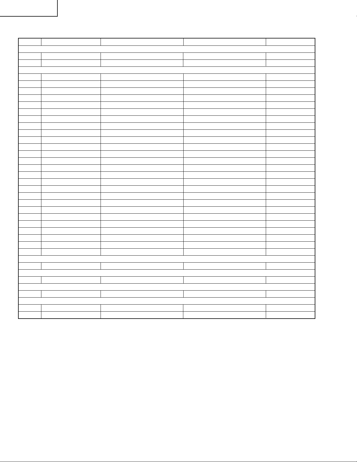
LIST OF CHANGED PARTS
Ref. No. Description Current (27N-S100) New (27N-S50) Note
PRINTED WIRING BOARD ASSEMBLIES
PWB-A Main Unit DUNTKA126WEK4 DUNTKA126WEL3
PWB-K S-Video Unit DUNTKA114WEK0 – Abolished
MAIN UNIT
IC951 I.C. VHiMM1113XF1E VHiMM1111XF1E
Q421 Transistor – VS2SB709AR/-1 or VS2SA1037KR-1 Added
L421 Coil – VP-XF680K0000 Added
C414 Capacitor – VCKYCY1CB104K Added
C421 Capacitor – VCCCCY1HH330J Added
C808 Capacitor – VCKYCY1HB102K Added
C956 Capacitor VCEA0A1CW106M – Abolished
RJ52 Resistor – VRS-CY1JF000J Added
RJ56 Resistor VRS-CY1JF000J – Abolished
RJ59 Resistor VRS-CY1JF000J – Abolished
R416 Resistor VRS-CY1JF332J – Abolished
R421 Resistor – VRD-MN2BE152J Added
R422 Resistor – VRS-CY1JF472J Added
R423 Resistor – VRS-CY1JF152J Added
R424 Resistor – VRS-CY1JF102J Added
R807 Resistor – VRS-CY1JF152J Added
R808 Resistor – VRD-RA2BE102J Added
R931 Resistor VRS-CY1JF750J – Abolished
R932 Resistor VRS-CY1JF750J – Abolished
R953 Resistor VRS-CY1JF101J – Abolished
R2012 Resistor VRS-CY1JF471J – Abolished
R2067 Resistor – VRS-CY1JF103J Added
R2069 Resistor VRS-CY1JF102J – Abolished
P931 Plug QPLGN0661CEZZ – Abolished
SC401 Socket QSOCN0585CEZZ – Abolished
SC402 Socket QSOCN0585CEZZ – Abolished
MISCELLANEOUS PARTS
Connecting Cord QCNW-0252MEZZ – Abolished
SUPPLIED ACCESORRIES
Operation Manual TiNS-6930MEZZ TiNS-6931MEZZ
PACKING PARTS
Packing Case SPAKC0658MEZZ SPAKC0657MEZZ
CABINET PARTS
1 Front Cabinet Ass’y CCABA1325MES0 CCABA1334MES0
2 Rear Cabinet GCABB1157MEKA GCABB1144MEKA
2
Page 3

27N-S50
Ref. No. Part No. ★ Description Code Ref. No. Part No. ★ Description Code
PAR TS LIST
PARTS REPLACEMENT
Replacement parts which have these special safety characteristics
identified in this manual; electrical components having such features
are identified by
and Schematic Diagrams. The use of a substitute replacement part
which dose no have the same safety characteristic as the factory
recommended replacement parts shown in this service manual may
create shock, fire or other hazards.
"HOW TO ORDER REPLACEMENT PARTS"
To have your order filled promptly and correctly, please furnish the
following informations.
1. MODEL NUMBER 2. REF . NO.
3. PART NO. 4. DESCRIPTION
in USA: Contact your nearest SHARP Parts Distributor to order.
å and shaded areas in the Replacement Parts Lists
For location of SHARP Parts Distributor, Please call TollFree; 1-800-BE-SHARP
★ MARK: SPARE PARTS-DELIVERY SECTION
▲ MARK: X- RAY RELATED PARTS
SUPPLIED ACCESSORIES
TiNS-6931MEN1 M Operation Manual AD
PACKING PARTS
(NOT REPLACEMENT ITEM)
SPAKC0657MEZZ – Packing Case —
CABINET PARTS
1 CCABA1334MES0 M Front Cabinet Ass’y BG
2 GCABB1144MEKA M Rear Cabinet AZ
Ref. No. Part No. ★ Description Code
PRINTED WIRING BOARD ASSEMBLIES
(NOT REPLACEMENT ITEM)
PWB-ADUNTKA126WEL3 – MAIN Unit —
PWB-A: DUNTKA126WEL3
MAIN UNIT
IC951 VHiMM1111XF1E J MM1111XF AE
Q421 VS2SB709AR/-1 J 2SB709AR AC
or
VS2SA1037KR-1
L421 VP-XF680K0000 J Peaking 68µH AB
C414 VCKYCY1CB104K J 0.1 16V Ceramic AB
C421 VCCCCY1HH330J J 33p 50V Ceramic AA
C808 VCKYCY1HB102K J 1000p 50V Ceramic AA
RJ52 VRS-CY1JF000J J 0 1/16W M-Ox. AA
R421 VRD-MN2BE152J J 1.5k 1/8W Carbon AA
R422 VRS-CY1JF472J J 4.7k 1/16W M-Ox. AA
R423 VRS-CY1JF152J J 1.5k 1/16W M-Ox. AA
R424 VRS-CY1JF102J J 1k 1/16W M-Ox. AA
R807 VRS-CY1JF152J J 1.5k 1/16W M-Ox. AA
R808 VRD-RA2BE102J J 1k 1/8W Carbon AA
R2067 VRS-CY1JF103J J 10k 1/16W M-Ox. AA
INTEGRATED CIRCUITS
TRANSISTOR
COIL
CAPACITORS
RESISTORS
[M-Ox.··· Metal Oxide]
3
Page 4

27N-S50
SCHEMATIC DIAGRAM:MAIN-1 Unit
H
G
F
E
D
C
B
A
121110987654321
4
5
Page 5

27N-S50
SCHEMATIC DIAGRAM:MAIN-2 Unit
H
G
F
E
D
C
B
A
121110987654321
6
7
Page 6

27N-S50
COPYRIGHT © 2000 BY SHARP CORPORATION
ALL RIGHTS RESERVED.
No part of this publication may be reproduced,
stored in a retrieval system, or transmitted in
any form or by any means, electronic, mechanical,
photocopying, recording, or otherwise, without
prior written permission of the publisher.
TQ0941-S
Jul. 2000 Printed in Japan
MI. KG
SHARP CORPORATION
AV Systems Group
Quality & Reliability Control Center
Yaita, Tochigi 329-2193, Japan
8
 Loading...