

Page 1
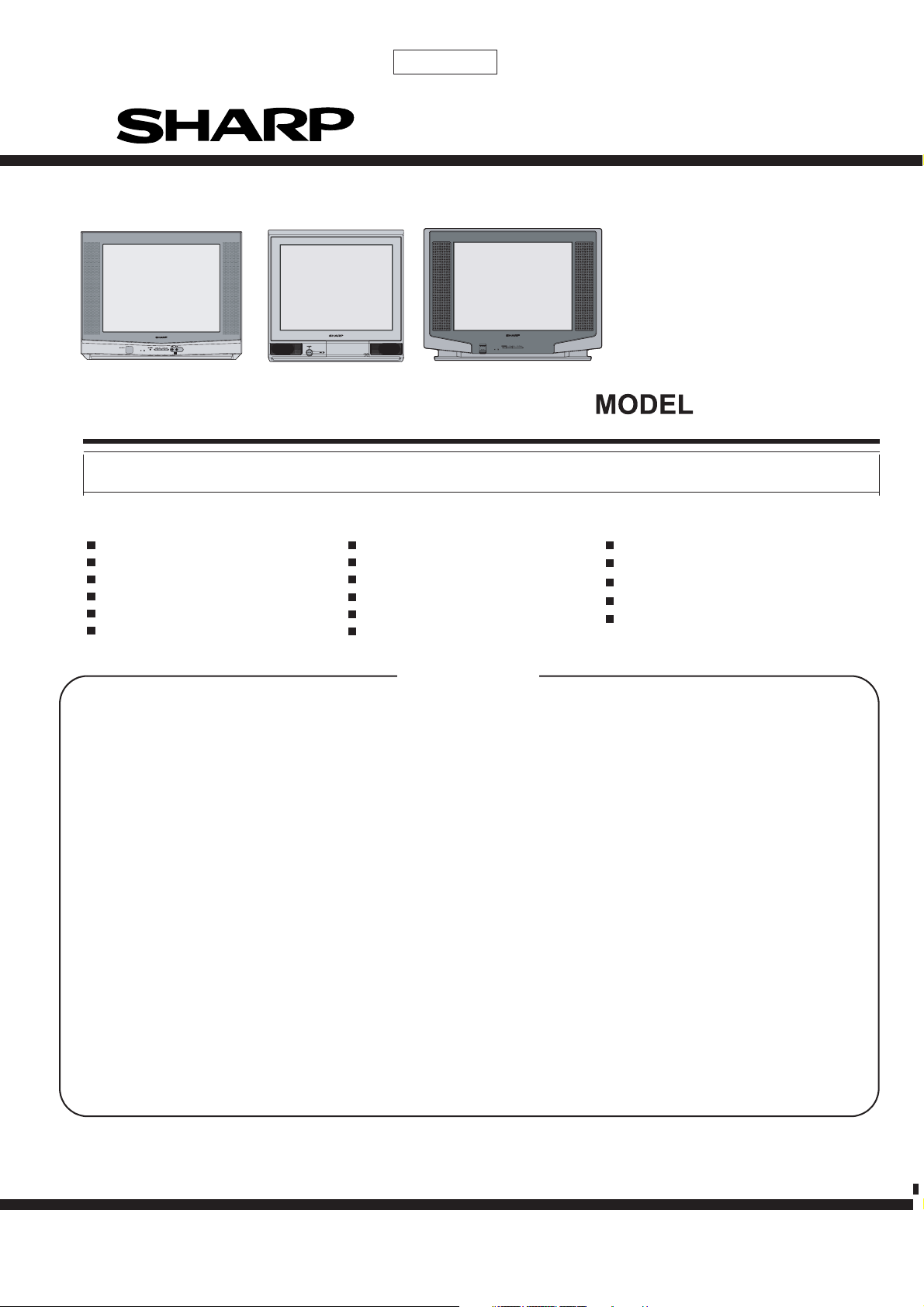
21F-PD250 / 21F-PT220 / 21F-PA18 / 21F-PA18(B)
1st Edition
SERVICE MANUAL
COLOUR TELEVISION
Chassis No.GA-7
21F-PA18
21F-PA18(B)
21F-PT220
In the interests of user-safety (Required by safety regulations in some countries) the set should be restored to its original condition and
only parts identical to those specified should be used.
21F-PA18
21F-PA18(B)
21F-PD250
21F-PD250
21F-PT220
FEATURES
PAL-B/G, D/K
Frequency Synthesizer Tuner
Full Auto System
100-CH Program Memory
CATV (Hyper Band Ready)
Hotel Mode
White Temperature Select
Off Timer
Blue Back Function
Aperture Control Circuit
Auto Fine Tuning
NTSC Colour Comb Filter
High Contrast Picture ( Black Stretch Circuit)
Child Lock
Multi Languages OSD (English/Thai)
Rear AV IN / OUT Terminals
Front AV-IN Terminal (Model 21F-PT220)
CONTENTS
CHAPTER 1. SPECIFICATIONS
[1] SPECIFICATIONS .........................................
CHAPTER 2. IMPORTANT SERVICE NOTES
[1] IMPORTANT SERVICE NOTES ....................
CHAPTER 3. ADJUSTMENT PRECAUTIONS
[1] ADJUSTMENT PRECAUTIONS ....................
[2] ADJUSTMENT .............................................
CHAPTER 4. MEMORY MAP
[1] MEMORY MAP...................................................
CHAPTER 5. TROUBLE SHOOTING FLOWCHART
[1] TROUBLE SHOOTING FLOWCHART ..........
3-14
1-1
2-1
3-1
4-1
5-1
CHAPTER 8. BLOCK DIAGRAM
[1] BLOCK DIAGRAM : MAIN UNIT...................
[2] BLOCK DIAGRAM : CRT UNIT ......................
CHAPTER 9. DESCRIPTION OF SCHEMATIC DIAGRAM
[1] DESCRIPTION OF SCHEMATIC DIAGRAM...
CHAPTER 10. WAVEFORMS
[1] WAVEFORMS ...............................................
CHAPTER 11. SCHEMATIC DIAGRAM
[1] SCHEMATIC DIAGRAM : CRT UNIT............
[2] SCHEMATIC DIAGRAM : MAIN UNIT ..........
8-1
8-9
9-1
10-1
11-1
11-2
CHAPTER 6. SOLID STATE DEVICE BASE DIAGRAM
[1] SOLID STATE DEVICE BASE DIAGRAM.....
CHAPTER 7. CHASSIS LAYOUT
[1] CHASSIS LAYOUT .......................................
6-1
7-1
CHAPTER 12. PRINTED WIRING BOARD ASSEMBLIES
[1] PWB-A : MAIN UNIT .....................................
[2] PWB-B : CRT UNIT.......................................
Parts Guide
12-1
12-3
WARNING
The chassis in this receiver is partially hot. Use an isolation transformer between the line cord plug and power receptacle, when servicing
this chassis. To prevent electric shock, do not remove cover. No user-serviceable parts inside. Refer servicing to qualified service personnel.
SHARP MANUFACTURING (THAILAND) CO.,LTD.
Page 2

21F-PD250 / 21F-PT220 / 21F-PA18 / 21F-PA18(B)
CHAPTER 1. SPECIFICATIONS
[1] SPECIFICATIONS
Convergence ................................................................................................................ Self Convergence System
Focus
Sweep Deflection ..................................................................................................................................... Magnetic
Intermediate Frequencies
Power Input ..................................................................................................................... 110 ~ 240V AC 50/60 Hz
Power Consumption
...............................................................................................................................
Picture IF Carrier ................................................................................................................................. 38.9MHz
Sound IF Carrier Frequency
............................................................................................................................................32.4MHz6.5MHz
............................................................................................................................................32.9MHz6.0MHz
............................................................................................................................................33.4MHz5.5MHz
Colour Sub-Carrier Frequency........................................................................................................... 34.47MHz
........................................................................................................................................
UNI-BI Focusing
83W
Audio Power Output Rating
Speaker
Size
..............................................................................................
Aerial Input Impedance
VHF/UHF .......................................................................................................................... 75 ohms Unbalanced
Receiving System ...............................................................................
Receiving Channel
VHF-Channels ......................................................................................... E2(48.25MHz) thru E12(224.25MHz)
UHF-Channels ..................................................................................... E21(471.25MHz) thru E69(855.25MHz)
Dimensions
....................................................................................... 21F-PA18 & 21F-PA18(B) :
....................................................................... 21F-PA18 & 21F-PA18(B) : 3W (rms)
21F-PD250 & 21F-PT220 : 5W (rms)
21F-PA18 & 21F-PA18(B) : 5 x 9 cm (1 pc)
21F-PD250 & 21F-PT220 : 5 x 9 cm (2 pcs)
..............................................................................................................
PAL-B/G, PAL - D/K, NTSC 3.58 MHz-B/G
.
S1(105.25MHz) thru S41(463.25HMz)
21F-PD250 :
16 ohms at 400 HzVoice Coil Impedance
Width: 502 mm
Height: 485 mm
Depth: 485 mm
Weight(approx): 22.5 kg
Width: 625 mm
Height: 470 mm
Depth: 495.5 mm
Weight(approx): 22 kg
21F-PT220 :
Weight(approx): 21.5 kg
Cabinet material ..................................................................................................................................... All Plastics
Width: 577 mm
Height: 465.5 mm
Depth: 480 mm
Specifications are subject to change without prior notice
1 – 1
Page 3

21F-PD250 / 21F-PT220 / 21F-PA18 / 21F-PA18(B)
TVE
CHAPTER 2. IMPORTANT SERVICE NOTES
[1] IMPORTANT SERVICE NOTES
Maintenance and repair of this receiver should be done by qualified service personnel only.
1. SERVICE OF HIGH VOLTAGE SYSTEM AND PICTURE TUBE
When servicing the high voltage system, remove static charge from it by connecting a 10K ohm resistor in series with an insulated wire (such as a test
probe) between picture tube dag and 2nd anode lead. (AC line cord should be disconnected from AC outlet.)
1) Picture tube in this receiver employs integral implosion protection.
2) Replace with the same type number of picture tube for continued safety.
3) Do not lift picture tube by the neck.
4) Handle the picture tube only when wearing shatterproof goggles and after discharging the high voltage completely.
2. X-RAY
This receiver is designed so that any X-Ray radiation is kept to an absolute minimum. Since certain malfunctions or servicing may produce potentially
hazardous radiation with prolonged exposure at close range, the following precautions should be observed:
1) When repairing the circuit, please make sure do not increase the high voltage of the set to more than 30.0kV (at beam 0µA).
2) To keep the set in a normal operation, please make sure it’s function at 26.5kV ± 1.0kV (at beam 1,100µA). The set has been factory - adjusted to
the above-mentioned high voltage.
*If there is a possibility that the high voltage fluctuates as a result of the repairs, never forget to check for such high voltage after the work.
3) Do not substitute a picture tube with unauthorizerd types and/or brands which may cause excessive X-ray radiation.
3. BEFORE RETURNING THE RECEIVER
Before returning the receiver to the user, perform the following safety checks.
1) Inspect all lead dress to make certain that leads are not pinched or that hardware is not lodged between the chassis and other metal parts in the
receiver.
2) Inspect all protective devices such as non-metal control knobs, insulating materials, cabinet backs, adjustment and compartment covers or
shields, isolation resistor-capacity networks, mechanical insulators etc.
2 – 1
Page 4

21F-PD250 / 21F-PT220 / 21F-PA18 / 21F-PA18(B)
(6)
e
CHAPTER 3.
ADJUSTMENT PRECAUTIONS
[1] ADJUSTMENT PRECAUTIONS
ADJUSTMENT PRECAUTIONS
This model's setting are adjusted in two different ways: through the I2C bus control and in
the conventional analog manner. The adjustments via the I2C bus control include preset-only
items and variable data.
CAUTION : MAKE SURE TV SET IN "NORMAL CONDITION" BEFORE SWITCH TO SERVICE MODE
FOR ADJUSTMENT.
1. Setting the service mode by the microprocessor.
(1) Press SERVICE key on the remote controller to set the TV set to SERVICE mode position,
and the microprocessor is in input mode. (Adjustment through the I2C bus control).
Service Mode also can be reached by by connecting MCU Pin 5 to ground.
(JA483 connect to JA484)
(2) Press the MENU key on the remote controller to get ready to select the mode
(Adjustment mode, Setting mode, Check mode and Option mode) one by one.
(3) Press the CH DOWN / UP key on the remote controller to select the item in Adjustment
mode, Setting mode or Option mode.
(4) Using the VOLUME UP/ DOWN key on the remote controller, the data can be modified.
Please wait approximately 200 msec for data storage in EEPROM before select to
another mode.
(5) In Check mode the data cannot be changed.
Press the SERVICE keyagain,it will switch to the NORMAL modeposition,and th
microprocessor is out of the SERVICE mode.
2. Factory Presetting.
(1) During POWER OFF (AC OFF), switch on service key (by connecting MCU Pin 5 to ground )
then follow by AC ON. Initial values are automatically preset only when a new EEPROM is used.
(Judge with the first 4 bytes ).
(2) The initial data are preset as listed in page 3-6 to 3-11.
(3) Make sure the data need modification or not (Initial data).
Precaution: If haven't done this initialization, it may possibly generate excessive Beam current.
3.
For reference please check with memory map RH-IXC129WJZZQ. (See Page 4-1 ~ 4-32).
3 – 1
Page 5

21F-PD250 / 21F-PT220 / 21F-PA18 / 21F-PA18(B)
1. ADJUSTMENT ITEM
***Below are the adjustment items that should be done, PLS FOLLOW THE PROCEDURE. Otherwise some adjustment items will
not be accurate.
NO *** ADJUSTMENT ITEM EFFECTIVE MODEL REVISION
1 BUS SET UP
2 OPTION SET UP
3H-VCO
4VIF-VCO
5S-TRAP fo
6RF-AGC
7 PURITY ADJ
8 CONVERGENCE ADJ
9 FOCUS ADJ
10 V-SHIFT (50 Hz)
11 H-SHIFT (50 Hz)
12 V-SIZE (50 Hz)
13 SCREEN
14 WHITE BALANCE
15 SUB-BRIGHTNESS
16 SUB-CONTRAST
17 SUB-COLOR
18 SUB-TINT
19 BEAM CURRENT CHECK
20 BEAM PROTECTOR CHECK
21 HV PROTECTOR CHECK
22 OTHER PROTECTOR CHECK
23 AV OUT CHECK
24 AV IN CHECK
25 CONTRAST CONTROL CHECK
26 COLOR CONTROL CHECK
27 BRIGHTNESS CONTROL CHECK
28 TINT CONTROL CHECK
29 SHARPNESS CONTROL CHECK
30 CH DISPLAY COLOR CHECK
31 NORMAL DISPLAY CHECK
32 WHITE TEMP CONTROL CHECK
33 COLOR SYSTEM CHECK
34 SOUND SYSTEM CHECK
35 NOISE MUTE CHECK
36 OSD LANGUAGE QUANTITY CHECK
37 SHOCK TEST CHECK
ALL MODELS
3 – 2
Page 6

21F-PD250 / 21F-PT220 / 21F-PA18 / 21F-PA18(B)
2. USER DATA IN SERVICE MODE
1) While SERVICE mode ON, EEPROM DATA will switch to the service data. Also, once SERVICE mode OFF, EEPROM will switch back to previous
USER DATA.
2) In the service mode, the user data establish as below,
USER DATA
CONTRAST MAX (60)
COLOUR CENT (0)
BRIGHTNESS CENT (0)
TINT CENT (0)
SHARPNESS CENT (0)
WHITE TEMP STANDARD
S-VOLUME MIN
BLUE BACK OFF
C SYSTEM AUTO
S SYSTEM *1
*1: For each CH, data is same as before switch to Service mode.
The flow of Mode list as following,
* Direct Key-in Mode for Service Items in Service Mode
RC CODE (HEX) R/C KEY NAME SERVICE-ITEM
80 POS 1 R-C UP (IN SERVICE MODE V00)
40 POS 2 G-C UP (IN SERVICE MODE V00)
C0 POS 3 B-C UP (IN SERVICE MODE V00)
20 POS 4 R-C DOWN (IN SERVICE MODE V00)
A0 POS 5 G-C DOWN (IN SERVICE MODE V00)
60 POS 6 B-C DOWN (IN SERVICE MODE V00)
E0 POS 7 R-D UP (IN SERVICE MODE V00)
10 POS 8 B-D UP (IN SERVICE MODE V00)
50 POS 0 B-D DOWN (IN SERVICE MODE V00)
E4 FLASHBACK R-D DOWN (IN SERVICE MODE V00)
E4 FLASHBACK Y-MUTE (BESIDES OF SERVICE MODE V00)
75 WHITE TEMP UP RF-AGC (V01)
F5 WHITE TEMP DOWN VIF-VC0 (V02)
C2 TUNE DOWN H-VCO (V03)
8D SHARPNESS DOWN SUB-CON (V04)
D6 BALANCE LEFT SUB-COL (V05)
0D SHARPNESS UP SUB-BRIGHT (V06)
36 BALANCE RIGHT SUB-TINT (V07)
46 TREBLE UP SUB-SHP (V08)
C6 TREBLE DOWN SUB-COL-YUV (V09)
26 BASS UP SUB-TINT-YUV (V10)
24 COLOUR UP V-SIZE (V11), V-SIZE60 (V17)
54 BRIGHTNESS DOWN V-SHIFT (V12), V-SHIFT60 (V18)
74 TINT DOWN H-SHIFT (V13), H-SHIFT60 (V19)
66 SURROUND UP SCM-BR (V14)
E6 SURROUND DOWN SCM-BB (V15)
C4 CONTRAST DOWN SUB-VOL (V16)
4C PICTURE S-TRAP-BG (V20)
CC HOLD S-TRAP-I (V21)
2C TEXT S-TRAP-DK (V22)
AC CANCEL S-TRAP-M (V23)
EC SIZE S-TRAP-574 (V24)
80 POS 1 R-C UP YUV (IN SERVICE MODE V25)
40 POS 2 G-C UP YUV (IN SERVICE MODE V25)
C0 POS 3 B-C UP YUV (IN SERVICE MODE V25)
20 POS 4 R-C DOWN YUV (IN SERVICE MODE V25)
A0 POS 5 G-C DOWN YUV (IN SERVICE MODE V25)
60 POS 6 B-C DOWN YUV (IN SERVICE MODE V25)
E0 POS 7 R-D UP YUV (IN SERVICE MODE V25)
10 POS 8 B-D UP YUV (IN SERVICE MODE V25)
50 POS 0 B-D DOWN YUV (IN SERVICE MODE V25)
E4 FLASHBACK R-D DOWN YUV (IN SERVICE MODE V25)
C1 AUTO ADJ FOR V01, V02, V03, V20, V21, V22, V23, V24
CA T-SET
81 SERVICE MODE
3 – 3
Page 7
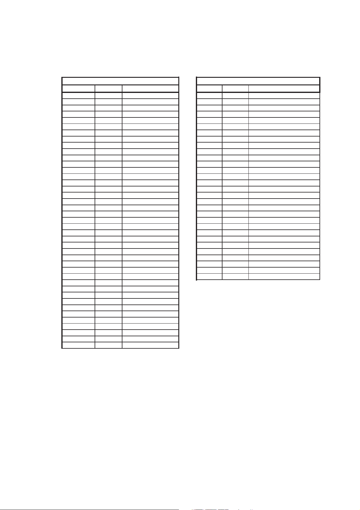
1) Please set the MCL to MCL4 as below :
(
)
2) After set the MCL, please set the INITIAL SETTING to INITIAL 9.
INITIAL 9 : For Thai ( All Channel Sound System are set to B/G )
21F-PD250 / 21F-PT220 / 21F-PA18 / 21F-PA18(B)
MCL4 (HEX AB)
CH-NO Fv
041
1 55.25 B/G 42
2 175.25 B/G 43
3 189.25 B/G 44
4 203.25 B/G 45
5 217.25 B/G 46
6 535.25 B/G 47
748
849
950
10 51
11 48.25 B/G 52
12 62.25 B/G 53
13 196.25 B/G 54
14 210.25 B/G 55
15 224.25 B/G 56
16 471.25 B/G 57
17 855.25 B/G 58
18 59
19 60
20 61
21 223.95 B/G 62
22 224.55 B/G 63
23 223.85 B/G 64
24 224.65 B/G 65
25 223.75 B/G 66
26 224.75 B/G 67
27 68
28 69
29 70
30
31 91.25 M
32 103.25 M
33 171.25 M
34 183.25 M
35 193.25 M
36 205.25 M
37 217.25 M
38 621.25 M
39
40
MHz
SOUND SYS CH-NO Fv (MHz)
MCL4(HEX AB)
SOUND SYS
*NOTE: PLL DATA OF ABOVE FREQ SHOULD TAKE THE ACCOUNT OF PIF SETTING IN SERVICE
OPTION O04 (VIF) BEFORE STORING INTO EEPROM
3 – 4
Page 8
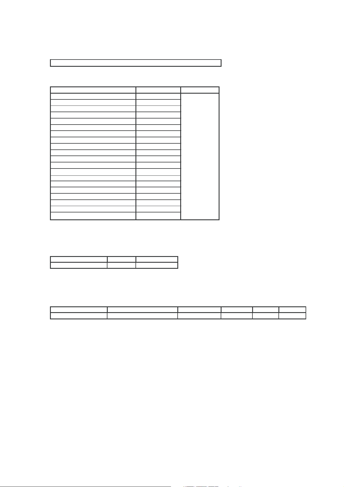
SHIPPING SETTING & CHECKING
(1) The following default data has been factory-set for the E2PROM follow by INITIAL DATA selected.
ITEMS DATA SETTING MODEL
LAST POWER ON
LAST TV/AV MODE TV MODE
LAST POSITION CH 1
FLASHBACK CHANNEL CH 1
1/2 DIGITENTR 2 DIGIT ENTRY
VOLUME 0 (Min)
BLUE BACK OFF
CHILD LOCK OFF
OFF TIMER --:-PASSWORD 0000
AFT ALL CH ON
COLOR SYSTEM ALL CH AUTO
SOUND SYSTEM B/G
SKIP ALL CH OFF
CONTRAST 60
COLOR +6
BRIGHTNESS 0
TINT 0(CENTER)
SHARPNESS +6
WHITE TEMP 0
ALL MODELS
21F-PD250 / 21F-PT220 / 21F-PA18 / 21F-PA18(B)
INITIAL LANGUAGE SOUND SYSTEM
9 (HEX EE) THAI B/G
FACTORY SETTING BY MODEL
(Reference: Geomagnetism Adjustment)
MODEL MAGNETIC FIELD(V, H) nT BACKGROUND LANG. S-SYS LANG QTY
THAI 20,000 40,000 12300°K THAI B/G 2
*NOTE FOR OSD TYPE:
2: ENGLISH / THAI
**This magnetic filed is in ITC CRT specification.
3 – 5
Page 9
21F-PD250 / 21F-PT220 / 21F-PA18 / 21F-PA18(B)
(
)
**AFTER INITIALIZED THE EEPROM (REFER TO FACTORY PRESETTING), READ DATA FROM
EEPROM ADDRESS 00H ~ 03H,AND COMPARE TO THE LIST BELOW, IF DIFFERENT,
INITIALIZE THE EEPROM.
ADDRESS DATA ADDRESS DATA
00H:
01H:
7CH
70H
02H:
03H:
78H
70H
*** There are four stages of service mode data. First stage data from V00~V32 (Adjustment Mode).
To go into second stage of service mode data, press MENU key.Second stage data from F01~F185(Setting Mode).
To go into third stage of service mode data, press MENU key.Third stage data is Check Mode.
To go into fourth stage of service mode data, press MENU key.Fourth stage data from O01~O37(Option Mode).
To go into fifth stage of service mode data, press MENU key.Fifth stage data is NVM Edit Mode.
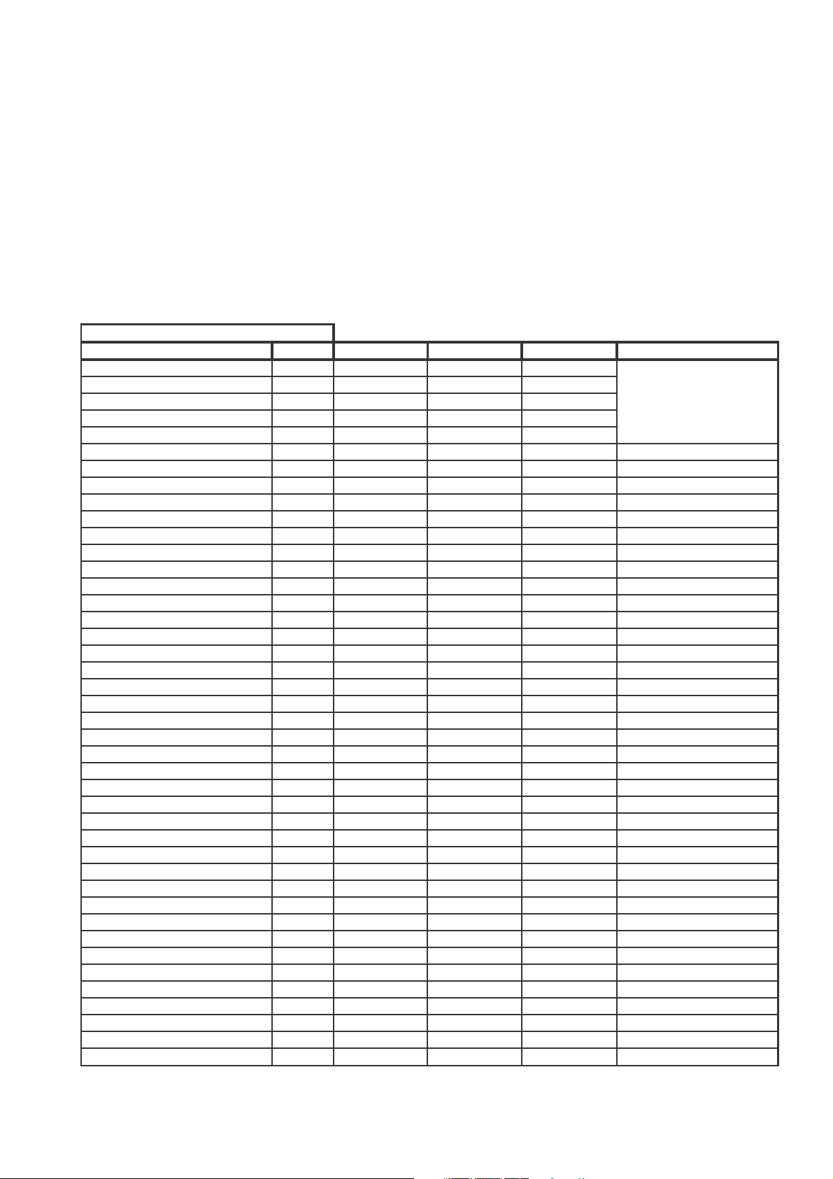
ADJUSTMENT MODE
FIRST STAGE
EEPROM ITEMS OSD DATA LENGTH INITIAL DATA FIX/ADJ/AUTO REMARK
R-DRIVE
B-DRIVE
R-CUT
G-CUT
B-CUT
RF-AGC
VIF-VCO
H-VCO
SUB-CON
SUB-COLOR
SUB-BRIGHT
SUB-TINT
SUB-SHP PRE
SUB-COLOR-YUV
SUB-TINT-YUV
V-SIZE
V-SHIFT
H-SHIFT
SCM-BR
SCM-BB
SUB-VOL
V-SIZE60
V-SHIFT60
H-SHIFT60
S-TRAP(BG)
S-TRAP(I)
S-TRAP(DK)
S-TRAP(M)
S-TRAP(574)
CUTOFF/BKGD YUV
R-DRI YUV
B-DRI YUV
R-CUT YUV
G-CUT YUV
B-CUT YUV
SUB-CON YUV
SUB-BRIGHT YUV
VS-CORRECT
VS-CORRECT_OFFSET
VLINEARITY
V LINEARITY_OFFSET
SUB-SHP OV
V00 0~127 63 ADJ
V00 0~127 63 ADJ
V00 0~255 127 ADJ
V00 0~255 127 ADJ
V00 0~255 127 ADJ
V01 0~127 50 AUTO
V02 0~63 31 AUTO
V03 0~7 3 AUTO
V04 0~127 100 ADJ
V05 0~127 63 ADJ
V06 0~255 127 ADJ
V07 0~127 63 ADJ
V08 0~63 43 *FIX
V09 0~127 90 *FIX
V10 0~127 63 FIX
V11 0~63 38 ADJ
V12 0~7 3 ADJ
V13 0~31 9 ADJ
V14 0~63 37 FIX
V15 0~63 22 FIX
V16 0~60 60 FIX
V17 -31~0~+31 0 *FIX
V18 -7~0~+7 -1 *FIX
V19 -15~0~+15 +2 FIX
V20 0~127 64 AUTO
V21 0~127 64 AUTO
V22 0~127 64 AUTO
V23 0~127 64 AUTO
V24 0~127 64 AUTO
V25
V25
V25
V25
V25
V25
0…127 63
0…127 63
0…255 127
0…255 127
0…255 127
FIX
FIX
FIX NO FUNCTON
FIX NO FUNCTON
FIX NO FUNCTON
V26 0~127 100 FIX
V27 0~255 127 FIX
V28 0~63 32 *FIX
V29 -13~+13 0 *FIX
V30 0~63 32 *FIX
V31 -13~+13 0 *FIX
V32 0~63 43 *FIX
PLS REFER TO
ADJ ITEM FOR
SCREEN AND
WHITE BALANCE
BUS SETUP
BUS SETUP
BUS SETUP
BUS SETUP
IF NECESSARY, ADJ
BUS SETUP
BUS SETUP
BUS SETUP
BUS SETUP
BUS SETUP
3 – 6
Page 10

SETTING MODE (SECOND STAGE)
(
)
(
)
)
EEPROM ITEMS FUNCTION OSD
C.CLIP-LVL CLIP LEVEL CONTRAST
RGB-CLIP CLIPPING OF RGB CONTRAST
BS BLACK STRETCH
ABCL ABCL PROCESSING (ACL
ABCL-GAIN ABCL PROCESSING GAIN
S-OUT-LVL-NOT USED
VIF-G P-IF DETECTION GAIN OUTPUT
SHPG SHARPNESS GAIN
SHPG-P SHARPNESS GAIN PAL
SHPG-S SHARPNESS GAIN SECAM
SHPG-N4 SHARPNESS GAIN N443
SHPG-N3 SHARPNESS GAIN N358
YDL Y SIGNAL DELAY
YDL-P Y SIGNAL DELAY PAL
YDL-S Y SIGNAL DELAY SECAM
YDL-N4 Y SIGNAL DELAY N443
YDL-N3 Y SIGNAL DELAY N358
YDL-AV Y SIGNAL DELAY AV
YDL-AV-P Y SIGNAL DELAY PAL (AV)
YDL-AV-S Y SIGNAL DELAY SECAM (AV)
YDL-AV-N4 Y SIGNAL DELAY N443 (AV)
YDL-AV-N3 Y SIGNAL DELAY N358 (AV)
YDL-YUV Y SIGNAL DELAY YUV
COL-AV (OFFSET) COLOUR OFFSET AV
COL-P (OFFSET) COLOUR OFFSET PAL
COL-S (OFFSET) COLOUR OFFSET SECAM
COL-N4 (OFFSET) COLOUR OFFSET N443
COL-N3 (OFFSET) COLOUR OFFSET N358
COL-ADJ (OFFSET) COLOUR OFFSET ADJUST
SHP-PRE-AV (OFFSET) SHARPNESS PRE OFFSET -AV
SHP-PRE-YUV (OFFSET) SHARPNESS PRE OFFSET -YUV
SHP-PRE-P (OFFSET) SHARPNESS PRE OFFSET -PAL
SHP-PRE-S (OFFSET) SHARPNESS PRE OFFSET -
SHP-PRE-N4 (OFFSET) SHARPNESS PRE OFFSET -N443
SHP-PRE-N3 (OFFSET) SHARPNESS PRE OFFSET -N358
SHP-OV-AV (OFFSET)
SHP-OV-YUV (OFFSET)
SHP-OV-P (OFFSET)
SHP-OV-S (OFFSET)
SHP-OV-N4 (OFFSET)
SHP-OV-N3 (OFFSET)
TINT-AV (OFFSET) TINT OFFSET AV
TINT-ADJ (OFFSET) TINT OFFSET ADJUST
TINT-YUV-ADJ (OFFSET) TINT YUV OFFSET ADJUST
R-R (OFFSET) R-DRIVE OFFSET WHEN WHITE
B-R (OFFSET) B-DRIVE OFFSET WHEN WHITE
R-B (OFFSET) R-DRIVE OFFSET WHEN WHITE
B-B (OFFSET) B-DRIVE OFFSET WHEN WHITE
CTRAP-ADJ
CTRAP-ADJ-P
CTRAP-ADJ-S
CTRAP-ADJ-N4
CTRAP-ADJ-N3
CONTROL OF RGB INPUT
CONTROL
PROCESSING)
AUDIO OUTPUT GAIN CONTROL
SECAM
SHARPNESS OV OFFSET -AV
SHARPNESS OV OFFSET - YUV
SHARPNESS OV OFFSET -PAL
SHARPNESS OV OFFSET SECAM
SHARPNESS OV OFFSET-N443
SHARPNESS OV OFFSET -N358
TEMP IS RED
TEMP IS RED
TEMP IS BLUE
TEMP IS BLUE
CENTER VALUE OF CHROMA
TRAP
CENTER VALUE OF CHROMA
TRAP PAL
CENTER VALUE OF CHROMA
TRAP SECAM
CENTER VALUE OF CHROMA
TRAP N443
CENTER VALUE OF CHROMA
TRAP N358
F01
F02
F03
F04
F05
F06
F07
F08
F09
F10
F11
F12
F13
F14
F15
F16
F17
F18
F19
F20
F21
F22
F23
F24
F25
F26
F27
F28
F29
F30
F31
F32
F33
F34
F35
F36
F37
F38
F39
F40
F41
F42
F43
F44
F45
F46
F47
F48
F49
F50
F51
F52
F53
DATA LENGTH
0(20H)/1(40H)
0 (enable)/
disable
1
0 (enable)/
1
disable
0 (ACL)/ 1(ABCL)
0(Lo)/1(Hi
0…127
0…7
0 (soft)/ 1(sharp)
0 (soft)/ 1(sharp)
0 (soft)/ 1(sharp)
0 (soft)/ 1(sharp)
0 (soft)/ 1(sharp)
0…7
0…7
0…7
0…7
0…7
0…7
0…7
0…7
0…7
0…7
0…7
-31…0…+31
-31…0…+31
-31…0…+31
-31…0…+31
-31…0…+31
-31…0…+31
-31…0…+31 +5
-31…0…+31 -5
-31…0…+31 -10
-31…0…+31 -15
-31…0…+31 -10
-31…0…+31 -10
-31…0…+31
-31…0…+31
-31…0…+31
-31…0…+31
-31…0…+31
-31…0…+31
-63…0…+63
-63…0…+63
-63…0…+63
-63…0…+63
-63…0…+63
-63…0…+63
-63…0…+63
0…3
0…3
0…3
0…3
0…3
INITIAL DATA FIX/ADJ/AUTO REM ARK
21F-PD250 / 21F-PT220 / 21F-PA18 / 21F-PA18(B)
0*FIX
0FIX
0FIX
0FIX
0FIX
95 FIX
4*FIX
0FIX
0FIX
0FIX
0FIX
1FIX
5FIX
5FIX
7FIX
5FIX
5FIX
6FIX
6FIX
7FIX
6FIX
6*FIX
6*FIX
+10 *FIX
0*FIX
+9 FIX
-8 FIX
-7 *FIX
0*FIX
*FIX
*FIX
*FIX
*FIX
*FIX
*FIX
+5
+5
0
-5
0
0
*FIX
FIX
*FIX
*FIX
*FIX
*FIX
0*FIX
0*FIX
0FIX
+8 *FIX
-10 *FIX
-3 *FIX
+13 *FIX
2FIX
2FIX
2FIX
2FIX
2FIX
BUS SETUP
NO FUNCTION
BUS SETUP
BUS SETUP
BUS SETUP
BUS SETUP
BUS SETUP
BUS SETUP
BUS SETUP
BUS SETUP
BUS SETUP
BUS SETUP
BUS SETUP
BUS SETUP
BUS SETUP
BUS SETUP
BUS SETUP
BUS SETUP
BUS SETUP
BUS SETUP
BUS SETUP
BUS SETUP
BUS SETUP
BUS SETUP
BUS SETUP
BUS SETUP
3 – 7
Page 11

SETTING MODE (SECOND STAGE)
(
)
(
)
(imp
)
21F-PD250 / 21F-PT220 / 21F-PA18 / 21F-PA18(B)
EEPROM ITEMS FUNCTION OSD
1W-TV VERT SYNC DETECTION MODE
1W-AV VERT SYNC DETECTION MODE
V-FREE (NO SYNC) SET VERTICAL TO FORCED
AFC2 (NO SYNC) HORIZONTAL AFC2 GAIN
GAMMA GAMMA CORRECTION QTY
BS-D/C BLACK STRETCH CONTROL
BS-GAIN BLACK STRETCH LEVEL
OM-DET OVER MODULATION DETECT
SL-TV SLICE LEVEL OF SYNC
SL-AV SLICE LEVEL OF SYNC
SL-YUV SLICE LEVEL OF SYNC
AS/FBP-TV AS-TV/AV/YUV SWITCH & CH
AS/FBP-AV AS-TV/AV/YUV SWITCH & CH
AS/FBP-YUV AS-TV/AV/YUV SWITCH & CH
VDL COLOUR DIFF. INPUT PHASE
UDL COLOUR DIFF. INPUT PHASE
AUTO-SCM-KIL-TV SECAM COLOUR KILLER
SECAM-BGP INTERNAL SECAM BGP TIMING
N45 INHIBIT 50Hz NTSC 4.43
OSD-POS-V50
OSD-POS-V60
OSD-POS-H OSD HORIZONTAL POSITION
CP CHARGE PUMP
AVL LEVEL AUTO VOLUME LIMIT LEVEL
AUTO-SCM-KIL-AV-YUV SECAM COLOUR KILLER
AFC1-GAIN-TV MSB OF HORIZONTAL AFC
AFC1-GAIN-AV MSB OF HORIZONTAL AFC
AFC1-GAIN-YUV MSB OF HORIZONTAL AFC
OSD LEVEL OSD LEVEL
TAKE-OFF-TV TAKEOFF/BPF OF CHROMA BPF
TAKE-OFF-AV TAKEOFF/BPF OF CHROMA BPF
TAKE-OFF-YUV TAKEOFF/BPF OF CHROMA BPF
C-ANGLE (103 DEG/ 95 DEG) CHROMA MODULATION ANGLE
AC-FAIL-WO-BRIGHT PICTURE BLACK LEVEL
FORCED-SCM-KIL-TV FORCED SECAM COLOUR
FORCED-SCM-KIL-AV-YUV FORCED SECAM COLOUR
CTI ADJ. COLOUR EDGE IMPROVEMENT
V-DEMUTE-DELAY VIDEO DEMUTE DELAY
S-DEMUTE-DELAY SOUND DEMUTE DELAY
FORAV(1WINDOW/2WINDOW)
FOR TV (1 WINDOW/2 WINDOW )
FREE RUN MODE
LEVEL
DETECTION TV
DETECTION AV
DETECTION YUV
CHANGE, FBP-FLYBACK PULSE
SLICE LEVEL (TV)
CHANGE, FBP-FLYBACK PULSE
SLICE LEVEL (AV)
CHANGE, FBP-FLYBACK PULSE
SLICE LEVEL (YUV)
ADJ
ADJ
SENSITIVITY (TV)
OSD VERTICAL POSITION (50Hz)
OSD VERTICAL POSITION (60Hz)
SENSITIVITY (AV/YUV)
GAIN1 (TV)
GAIN1 (AV)
GAIN1 (YUV)
PROCESSING TV
PROCESSING AV
PROCESSING YUV
(BRIGHT) CONTROL - AC
FAILURE
KILLER SENSITIVITY (TV)
KILLER SENSITIVITY (AV/YUV)
F54
F55
F56
F57
F58
F59
F60
F61
F62
F63
F64
F65
F66
F67
F68
F69
F70
F71
F72
F73
F74
F75
F76
F77
F78
F79
F80
F81
F82
F83
F84
F85
F86
F87
F88
F89
F90
F91
F92
DATA LENGTH
0(2W)/1(1W)
0(2W)/1(1W)
0(NORMAL) /
1(FREERUN)
0(NORMAL) /
1(DOWN)
0…3 0
0…15 10
0/1 0
0(disable)/
1
enable
0…7 2
0…7 4
0…7 4
0…3 2
0…3 2
0…3 2
0…3 0
0…3 0
0…3 1
0…3 0
0 (enable)/
disable
1
1…55 36
1…50 31
0…127 9
0/1 1
0 : 600mVrms
1 : 450mVrms
0…3 1
0…3 0
0…3 3
0…3 3
0:10%
1:30%
2:50%
3:70%
4:90%
0(BPF) /
1(TAKEOFF)
0(BPF) /
1(TAKEOFF)
0(BPF) /
1(TAKEOFF)
0(103DEG) /
1(95DEG)
0…255
0…3
0…3
0 (normal)/
rove
1
0~255
0~255
INITIAL DATA FIX/ADJ/AUTO REMARK
0FIX
1FIX
0*FIX
BUS SETUP
0FIX
*FIX
BUS SETUP
FIX
FIX
0
FIX
FIX
*FIX
BUS SETUP
FIX
*FIX
*FIX
*FIX
BUS SETUP
BUS SETUP
BUS SETUP
FIX
FIX
FIX
FIX
0
FIX
FIX
FIX
FIX
*FIX
0
FIX
BUS SETUP
FIX
FIX
FIX
FIX
3*FIX
BUS SETUP
1FIX
0FIX
0FIX
1*FIX
BUS SETUP
255 FIX
2FIX
2FIX
1FIX
0*FIX
0*FIX
BUS SETUP
BUS SETUP
3 – 8
Page 12

SETTING MODE (SECOND STAGE)
(TV)
(AV)
(
)
(UP)
21F-PD250 / 21F-PT220 / 21F-PA18 / 21F-PA18(B)
EEPROM ITEMS FUNCTION OSD
MER S-BOOSTER FREQ.
MEL1 S-BOOSTER LEVEL1
MEL2 S-BOOSTER LEVEL2
MEL3 S-BOOSTER LEVEL3
MEL4 S-BOOSTER LEVEL4
MEL5 S-BOOSTER LEVEL5
MEL6 S-BOOSTER LEVEL6
S-ST-POINT S-BOOSTER START POINT
S-SP-POINT S-BOOSTER STOP POINT
S-STEP S-BOOSTER STEP
POW-STORAGE CONTRAST/BRIGHTNESS
S-B-BASS S-BOOSTER BASS LIMITER
S-B-TREB S-BOOSTER TREBLE LIMITER
S-BASS S-BOOSTER BASS LIMITER
S-TREB S-BOOSTER TREBLE LIMITER
V-STD-TV
V-STD-AV
V-STD-YUV
HVCO-FREERUN-SHIFT HVCO-FREERUN-SHIFT
HVCO-PULLDOWN HVCO PULLDOW N
HVCO-PULLUP HVCO PULLUP
HVCO-PULLIN-UP HVCO PULLIN UP
PEAK-ACL PEAK ACL
APER-FREQ APER FREQ
R-DRI YUV OFFSET
B-DRI YUV OFFSET
R-CUT YUV OFFSET
G-CUT YUV OFFSET
B-CUT YUV OFFSET
CON YUV OFFSET
BRT YUV OFFSET
SHP ANT-ONII OFFSET
WAIT MD TIME
Contrast OFFSET
Bright OFFSET
CR-PEDESTEL-ADJ
CB-PEDESTEL-ADJ
SIF-PAL SOUND S/N SWITCH FOR PAL
AV2 BRIGHTNESS OFFSET
BASS OFFSET
TREBLE OFFSET
AS-SPEED-DN
AS-SPEED-UP
SIF-BPF-WIDE
SIF-BPF-WIDE-574
ACC-AMP-ON
TEST PATTERN
FSC-FREE FSC-FREE
MCUVOUT MCUVOUT
HALF-H KILLER HALF-H KILLER
V-AGC V-AGC
CONT NEWS
CONT MUSIC
CONT MOVIE
BRIGHT NEWS
BRIGHT MUSIC
CHARACTERISTIC CONTROL
INCREASE GRADUALLY
(WHEN S-BOOSTER ON)
(WHEN S-BOOSTER ON)
(WHEN S-BOOSTER OFF)
(WHEN S-BOOSTER OFF)
VERTICAL STANDARD SIGNAL
DETECTOR SWITCH
VERTICAL STANDARD SIGNAL
DETECTOR SWITCH
VERTICAL STANDARD SIGNAL
DETECTOR SWITCH
RGB OUTPUT RED GAIN OFFSET
(YUV)
RGB OUTPUT BLUE GAIN
OFFSET (YUV)
RGB OUTPUT-RED BIAS LEVEL
OFFSET (YUV)
RGB OUTPUT-GREEN BIAS
LEVEL OFFSET (YUV)
RGB OUTPUT-BLUE BIAS LEVEL
OFFSET (YUV)
SUB-CONTRAS OFFSET (YUV)
SUB-BRIGHT OFFSET (YUV)
SHARP ANT-ON II OFFSET FOR
VIDEO TONE
SETTING CYCLE PROCESS TIME
AT LOW POWER
CONTRAST (PICTURE LEVEL)
OFFSET
PICTURE BLACK LEVEL
(BRIGHT) OFFSET
Cr SIGNAL LEVEL ADJUSTMENT
Cb SIGNAL LEVEL ADJUSTMENT
AV2 BRIGHT OFFSET
BASS OFFSET
TREBLE OFFSET
AUTO SLICE SPEED SWITCH
(DOWN)
AUTO SLICE SPEED SWITCH
SIF BPF BANDWIDTH SELECTOR
SIF BPF BANDWIDTH SELECTOR
INCREASE CHROMA ACC AMP
GAIN
TEST PATTERN
CONTRAST SETTING- NEWS
CONTRAST SETTING- MUSIC
CONTRAST SETTING- MOVIE
BRIGHTNESS SETTING- NEWS
BRIGHTNESS SETTING- MUSIC
YUV
F93
F94
F95
F96
F97
F98
F99
F100
F101
F102
F103
F104
F105
F106
F107
F108
F109
F110
F111
F112
F113
F114
F115
F116
F117
F118
F119
F120
F121
F122
F123
F124
F125
F126
F127
F128
F129
F130
F131
F132
F133
F134
F135
F136
F137
F138
F139
F140
F141
F142
F143
F144
F145
F146
F147
F148
DATA LENGTH
0~255
0~255
0~255
0~255
0~255
0~255
0~255
0~60
0~60
0~60
0(DISABLE) /
1(ENABLE)
0…+10
0…+10
0…+10
0…+10
0(DISABLE) /
1(ENABLE)
0(DISABLE) /
1(ENABLE)
0(DISABLE) /
1(ENABLE)
0/1
0/1
0/1
0/1
0/1
0/1
-63…0…+63
-63…0…+63
-63…0…+63
-63…0…+63
-63…0…+63
-63…0…+63
-63…0…+63
-31…0…+31
0..2
-63…0…+63
-63…0…+63
0…15
0…15
0/1
-15…0…+15
-4…0…+4
-4…0…+4
0(DISABLE) /
1(ENABLE)
0(DISABLE) /
1(ENABLE)
0...3
0...3
0(NORMAL) /
1(GAIN UP)
0…15
0(NORMAL) /
1(FREE RUN)
0/1 0
0/1 1
0/1 0
0..60 30
0..60 50
0..60 60
-30..0..+30 0
-30..0..+30 0
INITIAL DATA FIX/ADJ/AUTO REMARK
70 FIX
150 FIX
156 FIX
163 FIX
165 FIX
170 FIX
180 FIX
21 FIX
60 FIX
7FIX
1FIX
+10 FIX
+10 FIX
+10 FIX
+10 FIX
0FIX
0FIX
0FIX
0FIX
0FIX
0FIX
0FIX
0FIX
0FIX
0FIX
0FIX
0FIX
0FIX
0FIX
0FIX
0FIX
0FIX
2FIX
0FIX
0FIX
8*FIX
8*FIX
BUS SETUP
BUS SETUP
0FIX
+7 FIX
0
0
*FIX
*FIX
BUS SETUP
BUS SETUP
0FIX
0FIX
0FIX
0*FIX
BUS SETUP
0FIX
0FIX
1
FIX
FIX
FIX
FIX
*FIX
*FIX
BUS SETUP
BUS SETUP
FIX
FIX
FIX
3 – 9
Page 13

SETTING MODE (SECOND STAGE)
(
)
(
)
(
)
)
)
)
EEPROM ITEMS FUNCTION OSD
BRIGHT MOVIE
COL NEWS
COL MUSIC
COL MOVIE
SHARP NEWS
SHARP MUSIC
SHARP MOVIE
SURR NEWS
SURR MUSIC
SURR MOVIE
TREBLE NEW S
TREBLE MUSIC
TREBLE MOVIE
BASS NEWS
BASS MUSIC
BASS MOVIE
S-BOOST NEWS
S-BOOST MUSIC
S-BOOST MOVIE
R-R-C
B-R-C
R-B-C
B-B-C
TRE OFFSET SUR ONII
VFREE2
VD3 / VD2 / VD1-TV
VD3 / VD2 / VD1-AV
VD3 / VD2 / VD1-YUV
SL-TV (WEAK)
VIF-AGC THRESHOLD
AFT OFFSET AFT OFFSET
VOL-START VOLUME START POINT
VOL-STEP VOLUME STEP
BASS-LIMIT1 BASS-LIMIT1
BASS-LIMIT2 BASS-LIMIT2
BASS-LIMIT3 BASS-LIMIT3
BASS-LIMIT4 BASS-LIMIT4
BRIGHTNESS SETTING- MOVIE
COLOUR SETTING- NEWS
COLOUR SETTING- MUSIC
COLOUR SETTING- MOVIE
SHARPNESS SETTING- NEWS
SHARPNESS SETTING- MUSIC
SHARPNESS SETTING- MOVIE
SURROUND SETTING- NEWS
SURROUND SETTING- MUSIC
SURROUND SETTING- MOVIE
TREBLE SETTING- NEWS
TREBLE SETTING- MUSIC
TREBLE SETTING- MOVIE
BASS SETTING- NEWS
BASS SETTING- MUSIC
BASS SETTING- MOVIE
S-BOOSTER SETTING- NEWS
S-BOOSTER SETTING- MUSIC
S-BOOSTER SETTING- MOVIE
R-GAIN OFFSET WHEN WHITE
TEMP IS RED CENTER TONE
B -GAIN OFFSET W HEN WHITE
TEMP IS RED CENTER TONE
R-GAIN OFFSET WHEN WHITE
TEMP IS BLUE CENTER TONE
B-GAIN OFFSET WHEN W HITE
TEMP IS BLUE CENTER TONE
TREBLE OFFSET WHEN
SURROUND ONII
V-FREE WHEN H LOCKED OUT
VD2 & VD1-VERT SYNC DETECT
MIN W IDTH MS B & LS B
RESPECTIVELY (TV)
VD2 & VD1-VERT SYNC DETECT
MIN W IDTH MS B & LS B
RESPECTIVELY (AV)
VD2 & VD1-VERT SYNC DETECT
MIN W IDTH MS B & LS B
RESPECTIVELY (YUV)
SL-TV (WEAK)
VIF AGC THRESHOLD
F149
F150
F151
F152
F153
F154
F155
F156
F157
F158
F159
F160
F161
F162
F163
F164
F165
F166
F167
F168
F169
F170
F171
F172
F173
F174
F175
F176
F177
F178
F179
F180
F181
F182
F183
F184
F185
DATA LENGTH
-30..0..+30 0
-30..0..+30 0
-30..0..+30 0
-30..0..+30 +10
-30..0..+30 -10
-30..0..+30 0
-30..0..+30 +5
0(OFF) / 1(ONI) /
2
ONII
0(OFF) / 1(ONI) /
2
ONII
0(OFF) / 1(ONI) /
2
ONII
-10..0..+10 -10
-10..0..+10 0
-10..0..+10 +5
-10..0..+10 -5
-10..0..+10 0
-10..0..+10 +10
0(OFF)/1(ON
0(OFF)/1(ON
0(OFF)/1(ON
-63…0…+63 +4
-63…0…+63 -5
-63…0…+63 -1
-63…0…+63 +6
-7... 0 ...+7 +1
0(OFF) / 1(ON) 0
0…7 1
0…7 3
0…7 3
0…7 7
0…127 127
0(OFF)
1(-50kHz)
2 (-100kHz)
3 (-150kHz)
4 (-200kHz)
0…60 60
0…60 0
0(0000)
1 (1001)
2(1010)
3(1011)
4(1100)
5(1101)
6(1110)
7(1111)
0(0000)
1 (1001)
2(1010)
3(1011)
4(1100)
5(1101)
6(1110)
7(1111)
0(0000)
1 (1001)
2(1010)
3(1011)
4(1100)
5(1101)
6(1110)
7(1111)
0(0000)
1 (1001)
2(1010)
3(1011)
4(1100)
5(1101)
6(1110)
7(1111)
INITIAL DATA FIX/ADJ/AUTO REMARK
21F-PD250 / 21F-PT220 / 21F-PA18 / 21F-PA18(B)
FIX
*FIX
FIX
*FIX
*FIX
FIX
*FIX
0
0
0
FIX
FIX
FIX
*FIX
*FIX
*FIX
*FIX
*FIX
*FIX
0
1
1
FIX
FIX
FIX
FIX
FIX
FIX
FIX
*FIX
FIX
FIX
FIX
FIX
FIX
FIX
0
*FIX
*FIX
*FIX
7
7
7
*FIX
*FIX
*FIX
7*FIX
BUS SETUP
BUS SETUP
BUS SETUP
BUS SETUP
BUS SETUP
BUS SETUP
BUS SETUP
BUS SETUP
BUS SETUP
BUS SETUP
BUS SETUP
BUS SETUP
BUS SETUP
BUS SETUP
BUS SETUP
BUS SETUP
BUS SETUP
BUS SETUP
3 – 10
Page 14
OPTION MODE (FOURTH STAGE)
(
)
,
,
(
)
)
(
)
y
(
)
(
)
(
)
(
)
EEPROM ITEMS
***HOTEL MODE
***HTL-POS
***HTL-VOL
VIF-NOT-USE
SECAM
N443(RF)
N358(RF)
Force-Col
S-SYS
AV
AV2
YUV
S-CTRL
NICAM-NOT-USE
A2-NOT-USE
TEXT-NOT-USE
BIL
LANG
SERCH-SP
R/C-MENU
LED-CONT
S-BOOSTER
SHARP-LOGO
TUNER BAND
WHITE BACK
BOOSTER
250 CHANNEL
AVL
**LNA TUNER
CHILD LOCK
NORMAL KEY
AV MODE
S-CTRL LIMIT
MP-IN
VIRGIN-MODE
WHITE-TEMP
LK MENU
21F-PD250 / 21F-PT220 / 21F-PA18 / 21F-PA18(B)
OSD
O01
O02
O03
O04
O05
O06
O07
O08
O09
O10
O11
O12
O13
O14
O15
O16
O17
O18
O19
O20
O21
O22
O23
O24
O25
O26
DATA LENGTH
0FF)/1(0N
0
0~99
--
0~60
0 (38.0) / 1 (38.9)
0 (DISABLE) / 1 (ENABLE)
0 (DISABLE) / 1 (ENABLE)
0 (DISABLE) / 1 (ENABLE)
0 (DISABLE) / 1 (ENABLE)
1(BG ONLY)~15(ALL)
0 (DISABLE) / 1 (ENABLE)
0 (DISABLE) / 1 (ENABLE)
0 (DISABLE) / 1 (ENABLE)
0 (DISABLE) / 1 (ENABLE)
0 (DISABLE) / 1 (ENABLE)
0 (DISABLE) / 1 (ENABLE)
0 (DISABLE) / 1 (ENABLE)
0 (DISABLE) / 1 (ENABLE)
1(350)~2(450)~3(550)~4(650)~5(750)
0 (ENABLE) / 1 (DISABLE)
0(ONELED)/1(TWOLED)
0
DISABLE)/1(ENABLE
0 (DISABLE) / 1 (ENABLE)
0 (DISABLE) / 1 (ENABLE)
0 (DISABLE) / 1 (ENABLE)
--
1~255
0/1
INITIAL DATA REMARK
0 : 100 channels (8k
O27
EEPROM)
1 : 250 channels (16k
EEPROM
0:fixto0
O28
1:fixto1
2 : AVL in SOUND MENU
O29 0(Alps) / 1(Matsushita) 0
O30
DISABLE)/1(ENABLE
0
Set items to default for
O31
0 : Picture and Sound
1 : Picture onl
O32
O33
O34
O35
O36
O37
DISABLE)/1(ENABLE
0
DISABLE)/1(ENABLE
0
0
DISABLE)/1(ENABLE
0
DISABLE)/1(ENABLE
0 : 3 modes
1 : 5 modes
0 (DISABLE) / 1 (ENABLE)
0
--
-1
1
1
1
0
15
1
1
1
1
0
0
0
0
63
3
0
0
0
0
0
1
0
0
2
1
0
1
0
1
0
0
0
OPTION SET UP
OPTION SET UP
OPTION SET UP
OPTION SET UP
OPTION SET UP
OPTION SET UP
OPTION SET UP
OPTION SET UP
OPTION SET UP
OPTION SET UP
OPTION SET UP
OPTION SET UP
OPTION SET UP
OPTION SET UP
OPTION SET UP
OPTION SET UP
OPTION SET UP
OPTION SET UP
OPTION SET UP
OPTION SET UP
OPTION SET UP
OPTION SET UP
OPTION SET UP
OPTION SET UP
OPTION SET UP
OPTION SET UP
OPTION SET UP
OPTION SET UP
OPTION SET UP
(ONLY FUNCTION IF
ANTE NNA BO OSTER
O26
=1)
OPTION SET UP
OPTION SET UP
OPTION SET UP
OPTION SET UP
OPTION SET UP
OPTION SET UP
OPTION SET UP
OPTION SET UP
*** HOTEL MODE
OPERATION OF HOTEL MODE:
WHEN CHANGE SERVICE DATA O01 TO 1, HOTEL MODE IS ON
WHEN HOTEL MODE IS ON,
1. Max volume data is determined by option setting HTL-VOL (O03)
2. Channel position after POWER ON is determined by option setting HOTEL-POS (O02) (if option setting
HOTEL-POS is not set, processing is according to last position data).
3. User data updates of EEPROM regarding the video and audio control is not allowed.
4. Preset mode is disable.
5. CH SETTING menu is not available.
** TUNER BAND
41.10MHz ~ 122.10MHz
122.15MHz ~ 143.10MHz
143.15MHz ~ 362.10MHz
362.15MHz ~ 426.10MHz
426.15MHz ~ 871.10MHz
P-Freq
VHF-H (0010)
UHF (1000)
BAND
TUNER BAND = 1TUNER BAND = 0 (same as GA6)
VHF-L (0001)VHF-L (0001)
VHF-H (0010)
UHF (1000)
3 – 11
Page 15

21F-PD250 / 21F-PT220 / 21F-PA18 / 21F-PA18(B)
ADJ ITEM: BUS SET UP (1 ST & 2ND STAGE SERVICE DATA)
ALL MODELS
V08
V09
V10
V17
V18
SERVICE ITEMS
SUB-SHP PRE
SUB-COLOR-YUV
SUB-TINT-YUV
V-SIZE60
V-SHIFT60
V28 VS-CORRECT
VC-CORRECT OFFSET
V29
V30 V LINEARITY
V LINEARITY OFFSET
V31
V32
SUB-SHP 0V
C.CLIP-LVL
F01
VIF-G
F07
YDL-AV-N3
F22
YDL-YUV
F23
F24 COL-AV
F25 COL-P
F28 COL-N3
F29 COL-ADJ
F30 SHP-PRE-AV
SHP-PRE-P (OFFSET)
F32
SHP-PRE-S (OFFSET)
F33
SHP-PRE-N4 (OFFSET)
F34
SHP-PRE-N3 (OFFSET)
F35
SHP-OV-AV (OFFSET)
F36
SHP-OV-P (OFFSET)
F38
SHP-OV-S (OFFSET)
F39
SHP-OV-N4 (OFFSET)
F40
SHP-OV-N3 (OFFSET)
F41
F42 TINT-AV
F43 TINT-ADJ
R-R (OFFSET)
F45
B-R (OFFSET)
F46
R-B (OFFSET)
F47
B-B (OFFSET)
F48
V-FREE (NO SYNC)
F56
GAMMA
F58
SL-AV
F63
AS/FBP-TV
F65
AS/FBP-AV
F66
AS/FBP-YUV
F67
CP
F76
OSD LEVEL
F82
C-ANGLE (103 DEG/ 95 DEG)
F86
F91 V-DEMUTE-DELAY
F92 S-DEMUTE-DELAY
SHP-ANT-ONII OFFSET
F124
CR-PEDESTEL-ADJ
F128
CB-PEDESTEL-ADJ
F129
F132 BASS OFFSET
F133 TREBLE OFFSET
SIF-BPF-WIDE
F136
F144 CONT NEWS
F145 CONT MUSIC
F150 COL NEWS
F152 COL MOVIE
F153 SHARP NEWS
F155 SHARP MOVIE
TREBLE NEW S
F159
TREBLE MUSIC
F160
TREBLE MOVIE
F161
F162
BASS NEWS
BASS MUSIC
F163
BASS MOVIE
F164
TRE OFFSET SUR ONII
F172
AFT OFFSET
F179
VOL-START
F180
VOL-STEP
F181
BASS-LIMIT1
F182
BASS-LIMIT2
F183
BASS-LIMIT3
F184
F185
BASS-LIMIT4
38
90
63
+4
-2
44
-9
36
+3
38
1
7
5
6
+4
+12
+8
+14
+1
+7
+2
+7
+7
+1
+7
+2
+7
+7
+7
+2
0
-9
-6
+8
1
1
2
3
3
3
0
4
0
25
40
0
8
8
0
0
0
50
60
-5
+6
-6
+6
-10
0
+5
-5
0
+10
+1
2
60
0
7
7
7
7
REMARK
ADJUST IF NECESSARY
TO IMPROVE
3 – 12
Page 16
ADJ ITEM: OPTION SET UP (4TH STAGE SERVICE DATA)
)
)
)
)
)
)
)
)
(RF)
21F-PD250 / 21F-PT220 / 21F-PA18 / 21F-PA18(B)
SERVICE ITEMS
O01
HTL MODE
O02
HTL-POS
HTL-VOL
O03
HSYNC-JUDGE
O04
SECAM
O05
N443(RF
O06
N358
O07
FORCE-COL
O08
S-SYS
O09
AV
O10
AV2
O11
YUV
O12
S-CTRL
O13
NICAM-NOT-USE
O14
A2-NOT-USE
O15
TEXT-NOT-USE
O16
BIL
O17
LANG 1~255
O18
SEARCH-SP
O19
R/C MENU
O20
LED-CONT
O21
S-BOOSTER
O22
SHARP-LOGO
O23
O24
TUNER BAND
O25
WHITE BACK
O26
BOOSTER
O27 250 CHANNEL
O28
AVL
O29 LNA TUNER
O30 CHILD LOCK
O31 NORMAL KEY
O32 AV MODE
O33 S-CTRL LIMIT
O34 MP-IN
O35 VIRGIN-MODE
O36 W HITE-TEMP
O37 LK MENU
0(0FF)/1(0N)
0~99,-0~60,--
0 (DISABLE) / 1 (ENABLE)
0 (DISABLE) / 1 (ENABLE)
0 (DISABLE) / 1 (ENABLE)
0 (DISABLE) / 1 (ENABLE)
0 (DISABLE) / 1 (ENABLE)
1(BG ONLY)~15(ALL)
0 (DISABLE) / 1 (ENABLE)
0 (DISABLE) / 1 (ENABLE)
0 (DISABLE) / 1 (ENABLE)
0 (DISABLE) / 1 (ENABLE)
0 (DISABLE) / 1 (ENABLE)
0 (DISABLE) / 1 (ENABLE)
0 (DISABLE) / 1 (ENABLE)
0 (DISABLE) / 1 (ENABLE)
1(350)~2(450)~3(550)~4(650)~5(750)
0 (ENABLE) / 1 (DISABLE)
0(ONELED)/1(TWOLED)
0 (DISABLE) / 1 (ENABLE)
0 (DISABLE) / 1 (ENABLE)
0/1
0(DISABLE)/1(ENABLE
0 (DISABLE) / 1 (ENABLE)
0(100 channels) /1(250 channels)
0(fixto0)~1(fixto1)~2(AVLin
SOUND MENU)
0 (Alps) / 1 (Matsushita)
0(DISABLE)/1(ENABLE
0 (PICTURE & SOUND) /1 (PICTURE
ONLY)
0(DISABLE)/1(ENABLE
0(DISABLE)/1(ENABLE
0(DISABLE)/1(ENABLE
0(DISABLE)/1(ENABLE
0(3MODES)/1(5MODES
0 (DISABLE) / 1 (ENABLE)
21F-PT220
0
--
-0
0
0
1
0
5
1
1
0
0
0
0
0
1
5
1
0
0
0
0
0
0
0
0
0
0
1
0
0
0
0
0
0
0
21F-PA18
21F-PA18(B)
21F-PD250
0
--
-0
0
0
1
0
5
1
0
0
0
0
0
0
1
5
1
0
0
0
0
0
0
0
0
0
0
1
0
0
0
0
0
0
0
3 – 13
Page 17
21F-PD250 / 21F-PT220 / 21F-PA18 / 21F-PA18(B)
[2] ADJUSTMENT
ADJUSTMENT PRECAUTION: Makesure TV Set is in “Normal Condition” before switch to Service Mode for Adjustment.
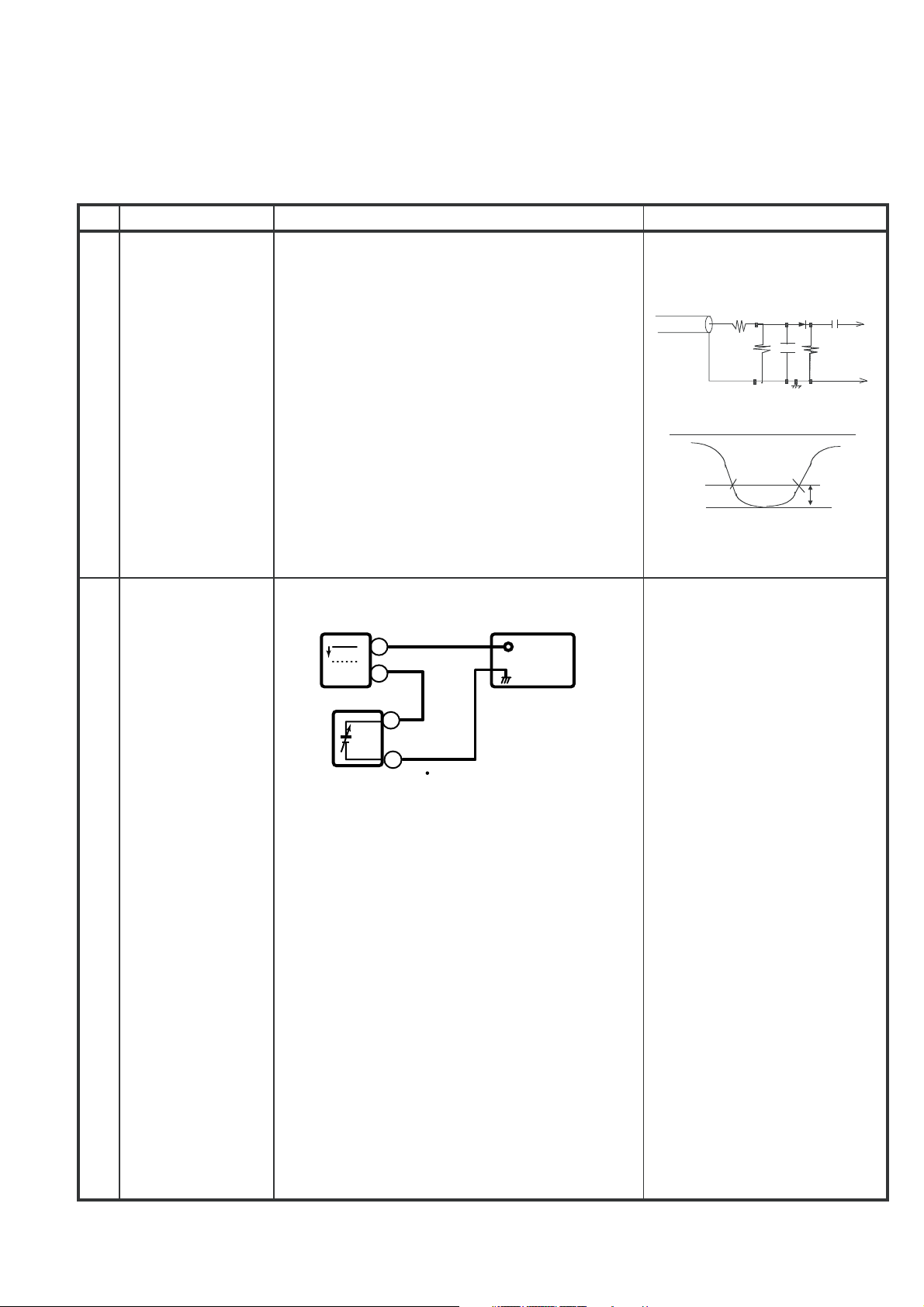
1. PIF ADJUSTMENT
No.
Adjustment point
Tuner IFT
1 1. Get the tuner ready to receive the CH. E - 9
( PRESET )
Adjustment procedure/conditions Waveform and others
signal,but with no signal input.
Adjust the PLL data.
2. Connect the sweep generator's output cable to
the tuner antenna. ( RF SWEEP )
3. Adjust the sweep generator's to 80dBµV.
4. Connect the response lead ( use LOW IMPEDANCE probe with wave detector ; see Fig.1 ) to
the tuner's IF output terminal. ( This terminal must
have the probe alone connected ).
5. Set the RF AGC to 0 - 6 V with no saturation with
the waveform.
6. Adjust the tuner IF coil to obtain the waveform as
shown in Fig. 2.
Note: Be sure to keep the tuner cover in posi-
tion during this adjustment.
RF-AGC
2
TAKE OVER
POINT ADJUSTMENT
2
CBUS
(I
CONTROL)
(AUTO &
Oscilloscope
+
0.1V
-
+
TP201
TV Set
MANUAL ADJ)
-
Bias box
Bias box: About 4.5 V
Fig. 3-1
1000p
10k
Oscilloscope
100k
1n60
1000p
IF OUT
75ohm
Fig.1
E-9 CH
PC
-1.5+/-0.8dB
Fig.2
* for Auto ADJ
1)Receive “PAL COLOUR BAR”
signal.
signal strength: 56
±1dBµV(75
ohm open)**
1)Go to service mode.
2)Go to service data V01, press
R/C to operate auto key (Hex
C1) and confirm the ‘OK’
display on the screen.
3)If appear NG, increase data
some step and pls repeat step
4)Proceed step 4 & 5 in manual
mode.
2.
3 – 14
Page 18
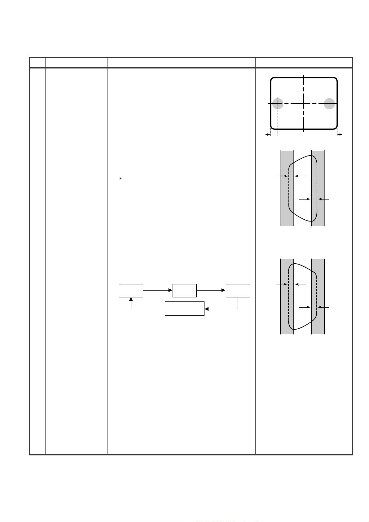
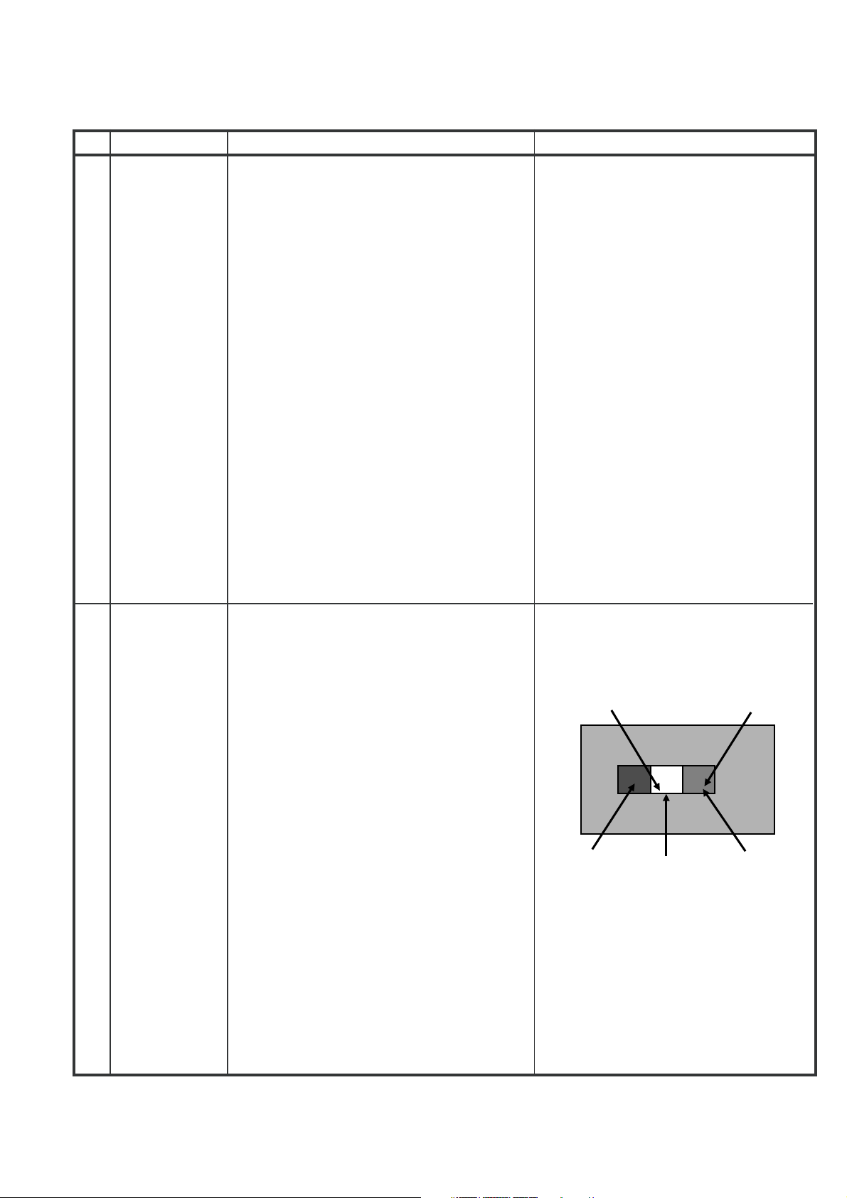
2. PURITY ADJUSTMENT
21F-PD250 / 21F-PT220 / 21F-PA18 / 21F-PA18(B)
No.
Adjustment point
PURITY ADJ.
1
(No need if used
ITC CRT)
Adjustment procedure/conditions Waveform and others
1. Receive the GREEN-ONLY signal. Adjust the
beam current to ~700 µA .
2. Degauss the CRT enough with the degausing coil.
Note: Follow the Job Instruction Sheet to adjust
the magnetic field.
(Reference: page 3-5)
3. Maintain the purity magnet at the zero magnetic
field and keep the static convergence roughly
adjusted.
4. Observe the points a, b,as shown in Fig. 1-1
through the microscope. Adjust the landings to A
rank requirement.
5. Orient the raster rotation to 0 eastward.
6. Tighten up the deflection coil screws.
Tightening torque: 108 ± 20 N (11kgf ± 2 kgf)
7. Make sure the CRT corners landing meet the A
rank requirements. If not, stick the magnet sheet
to correct it.
Note: This adjustment must be done after
warming up the unit for 30 minutes or
µ
longer with a beam current over 700
Note:
Set to service mode by remote con-
A.
troller then press factory process R/C
RGB key to change to RGB mono colour mode.
* For the following colours press R/C RGB(Hex 7E)
key to change.
a
30mm 30mm
Fig. 1-1
b
A
B
A=B
Fig. 1-2
Rank "A"
(on the right of the CRT)
GREEN
ONLY
BLUE
ONLY
Signal-colour
screen cleared
A
RED
ONLY
B
A=B
Fig. 1-3
Rank "A"
(on the left of the CRT)
* Press R/C RGB key for 1 sec-
ond in NORMAL MODE, the
colour will change to RGB
mono colour mode.
3 – 15
Page 19
3. CONVERGENCE ADJUSTMENT
21F-PD250 / 21F-PT220 / 21F-PA18 / 21F-PA18(B)
No.
1
Adjustment point
CONVERGENCE
ADJ.
(Tobedone
after the purity
adjustment.)
(No need if used
ITC CRT)
Adjustment procedure/conditions Waveform and others
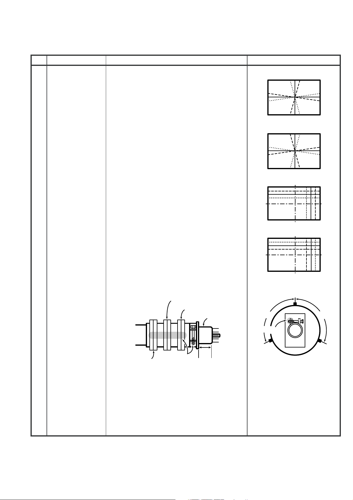
1. Receive the "Crosshatch Pattern" signal.
2. Using the remote controller, call NORMAL mode.
Static convergence
1. Turn the 4-pole magnet to a proper opening angle in order to superpose the blue and red colours.
2. Turn the 6-pole magnet to a proper opening angle in order to superpose the green colour over
the blue and red colours.
Dynamic convergence
1. Adjust the convergence on the fringes of the
screen in the following steps.
a) Fig. a: Drive the wedge at point "a" and swing
the deflection coil upward.
b) Fig. b: Drive the wedge at point "b" and "c" and
swing the deflection coil downward.
c) Fig. c: Drive the "c" wedge deeper and swing
the deflection coil rightward.
d) Fig. d: Drive the "b" wedge deeper and swing
the deflection coil leftward.
2. Fix all the wedges on the CRT and apply glass
tape over them.
3. Apply lacquer to the deflection yoke lock screw,
magnet unit (purity, 4-pole, 6-pole magnets) and
magnet unit lock screw.
BGR
B
G
R
Fig. a
RGB
R
G
B
Fig. b
B
RGB
G
R
Fig. c
R
BGR
G
B
Finally received the Red-only and Blue-only signals to make sure there is no other colours on the
screen.
4-pole magnet
6-pole magnet
CRT neck
Lacquer
Purity magnet
20mm
About
100Deg
Lacquer
Wedge
"b"
Fig. d
Wedge "a"
About
100Deg
Wedge
"c"
3 – 16
Page 20

4. H-VCO, VIF-VCO & S-TRAP fo ADJUSTMENT
21F-PD250 / 21F-PT220 / 21F-PA18 / 21F-PA18(B)
No.
1
2
Adjustment point
H-VCO ADJ
2
CBUS
(I
CONTROL)
(AUTO &
MANUAL ADJ)
VIF-VCO ADJ
2
CBUS
(I
CONTROL)
(AUTO &
MANUAL ADJ)
Adjustment procedure/conditions Waveform and others
(MANUAL ADJ)
1) In No signal (RASTER) condition.
2) Go to service mode, choose service data V03.
3) Connect oscilloscope to IC801 pin13 (H-OUT),
adj
V03
until freq become
15.625±0.15 KHz
(Auto Adj)
1) In No signal (RASTER) condition.
2) Go to service mode.
3) Choose service data V03, by pressing R/C Auto
(Hex C1) key, OSD will appear “OK” at screen.
4) If appear “NG” pls repeat step 3.
(Manual ADJ)
1) In No signal (RASTER) condition.
2) Go to service mode, choose service data V02.
3) Connect oscilloscope to IC801 pin7 (AFT),
adj
V02
until voltage become
2.5±1V
.
(Auto Adj)
1) In No signal (RASTER) condition.
2) Go to service mode, choose service data V02.
3) Press the R/C Auto (Hex C1) key, OSD will appear
“OK” at screen.
4) If appear “NG” pls repeat step 3.
This adjustment must be done
after aging at least 3 minutes.
S-TRAP fo
3
ADJ
2
CBUS
(I
CONTROL)
(AUTO &
MANUAL ADJ)
(Manual ADJ)
1) In No signal (RASTER) condition.
2) Go to service mode, choose service data V21.
3) Connect oscilloscope to TP 801, adj V21 until
voltage become Min (below 5 V).
4) After that pls adj service data V20 same as
“V21”, V22 to “V21+1”, V23 to “V21-2”.
(Auto Adj)
1) In No signal (RASTER) condition.
2) Go to service mode, choose service data
V21.
(S-TRAP I).
3) Press the R/C Auto (Hex C1) key, OSD will appear
“OK” at screen.
4) If appear “NG” pls repeat step 3.
5) Adjust V24 (S-TRAP 574) by repeating step 3 &
4 at final line after aging TV set to get accurate
data.
*CAUTION :
Make sure to adjust V24 at final
line after aging the TV set.
3 – 17
Page 21
21F-PD250 / 21F-PT220 / 21F-PA18 / 21F-PA18(B)
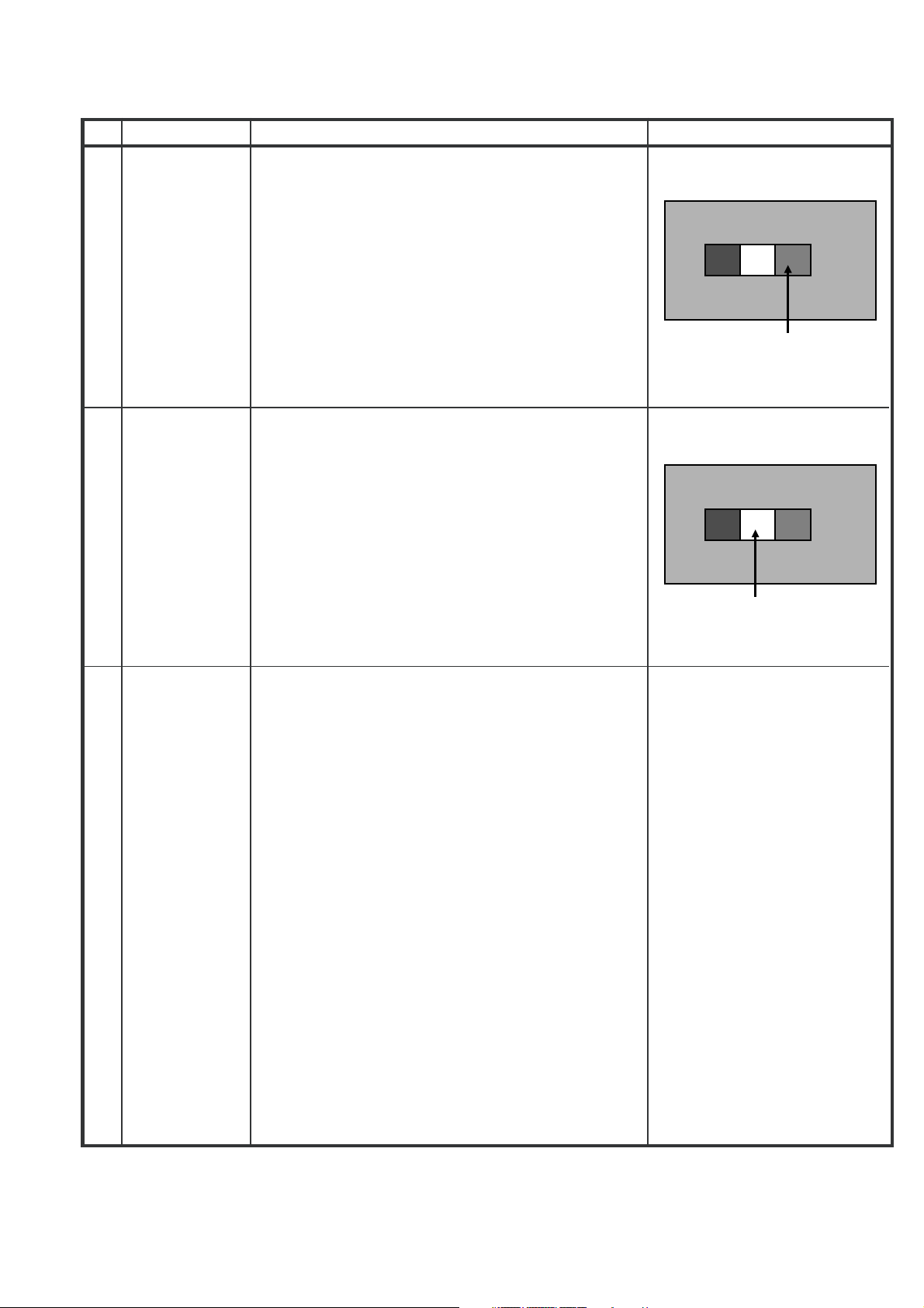
5. SCREEN, WHITE BALANCE, SUB-BRIGHTNESS & SUB-CONTRAST ADJUSTMENT
No.
Adjustment point
1
SCREEN
ADJUSTMENT
2
(I
CBUS
CONTROL)
Adjustment procedure/conditions Waveform and others
1) In window pattern signal condition.
2) Go to service mode, then select V00.
3)
By pressing R/C key S-Mute (Hex E8), R-D
auto switch to 63, B-D auto switch to 63, R-
C auto switch to 127, G-C auto switch to
127, B-C auto switch to 127, Subbrightness V06 auto switch to 127.
Y-mute & Vertical off, screen will be in
vertical cut-off condition.
4)
Adjust the Screen so that cut-off line ap-
R-CUTOFF (R-C) UP
R-CUTOFF (R-C) DOWN
G-CUTOFF (G-C) UP
G-CUTOFF (G-C) DOWN
B-CUTOFF (B-C) UP
B-CUTOFF (B-C) DOWN
R-DRIVE (R-D) UP
R-DRIVE (R-D) DOWN
B-DRIVE (B-D) UP
B-DRIVE (B-D) DOWN
pear in low bright, then judge that whether
the cut-off line appear in Red or Green or
Blue color, in this condition between R-C &
G-C & B-C, fix the data of the color appear
in cut-off line and adj the other two cut-off
data (Note 1) so that cut-off line color become white.
RC key "1" (HEX 80)
RC key "4" (HEX 20)
RC key "2" (HEX 40)
RC key "5" (HEX A0)
RC key "3" (HEX C0)
RC key "6" (HEX 60)
RC key "7" (HEX E0)
RC key "Flashback" (HEX E4)
RC key "8" (HEX 10)
RC key "0" (HEX 50)
2
WHITE
BALANCE ADJ
(to be done
after screen
adj)
2
CBUS
(I
CONTROL)
5)
Turn the screen VR of FBT so that cut-off
line just disappear and use R/C by press-
ing key S-Mute (Hex E8) to disable the Y-
mute & V-cut so that picture appear in normal mode.
WHITE (HIGH BEAM) ( In Window Pattern
1)
Signal)
First use Minolta Color Analyzer CA100, let
the gun point at Dark White position (as
drawing attach), Adj V06 until LUMI-
NANCE Y become 5 cd/m2, then let the
gun point at White position ( as drawing attach), Adj V04 until LUMINANCE Y become: 160 cd/m2.
Adj the R-D & B-D until the axis of color
temperature become
o
12300
K X:0.272
Y:0.275
DARK WHITE (LOW BEAM) (In Window
2)
Pattern Signal)
Let the gun point at Dark White position, if
the color temperature data shift away from
the data adjusted in step 1, adjust R-C, G-
C & B-C but between them, first color
appears in Screen adj item 1)-4 is fixed,
adj the other two so that to obtain the similaraxisasabove.
** Repeat step 1 & 2 to get a regulated
position
5.5% IRE
*Note :
WINDOW PATTERN SIGNAL
White
50% IRE
Signal using W/B Pattern Generator
SX-1006 (IWATSU) or equivalent.
Window Pattern Signal output level
are as above:
Dark White
9.5% IRE
3 – 18
Page 22
No.
Adjustment point
21F-PD250 / 21F-PT220 / 21F-PA18 / 21F-PA18(B)
Adjustment procedure/conditions Waveform and others
SUB-
3
BRIGHTNESS
(to be done
after screen,
white balance
adj)
(12C BUS
CONTROL)
4
SUBCONTRAST
(to be done
after screen,
white balance
adj,
sub-brightness adj)
(I
CONTROL)
2
CBUS
1) In Window Pattern Signal condition.
2)
Using Minolta Color Analyzer CA-100, let the
gun point at Dark White position (as attach
drawing), adjust V06 Bus data until
LUMINANCEY=3±0.5cd/m2.
1) In Window Pattern Signal condition.
2)
Using Minolta Color Analyzer CA-100, let the
gun point at White position (as attach drawing),
adjust V04 Bus data until LUMINANCE Y = 160
±10cd/m2
WINDOW PATTERN SIGNAL
Dark White
WINDOW PATTERN SIGNAL
White
Beam Current
5
Check
1) Receive the “Monoscope Pattern” signal.
2) Press R/C to set Picture NORMAL condition.
3) Connect the DC miliammeter between TP 603
(+)&TP602(-).
(Full Scale: 3mA Range)
µ
4) Beam current must be within 1100±100
A.
3 – 19
Page 23
21F-PD250 / 21F-PT220 / 21F-PA18 / 21F-PA18(B)
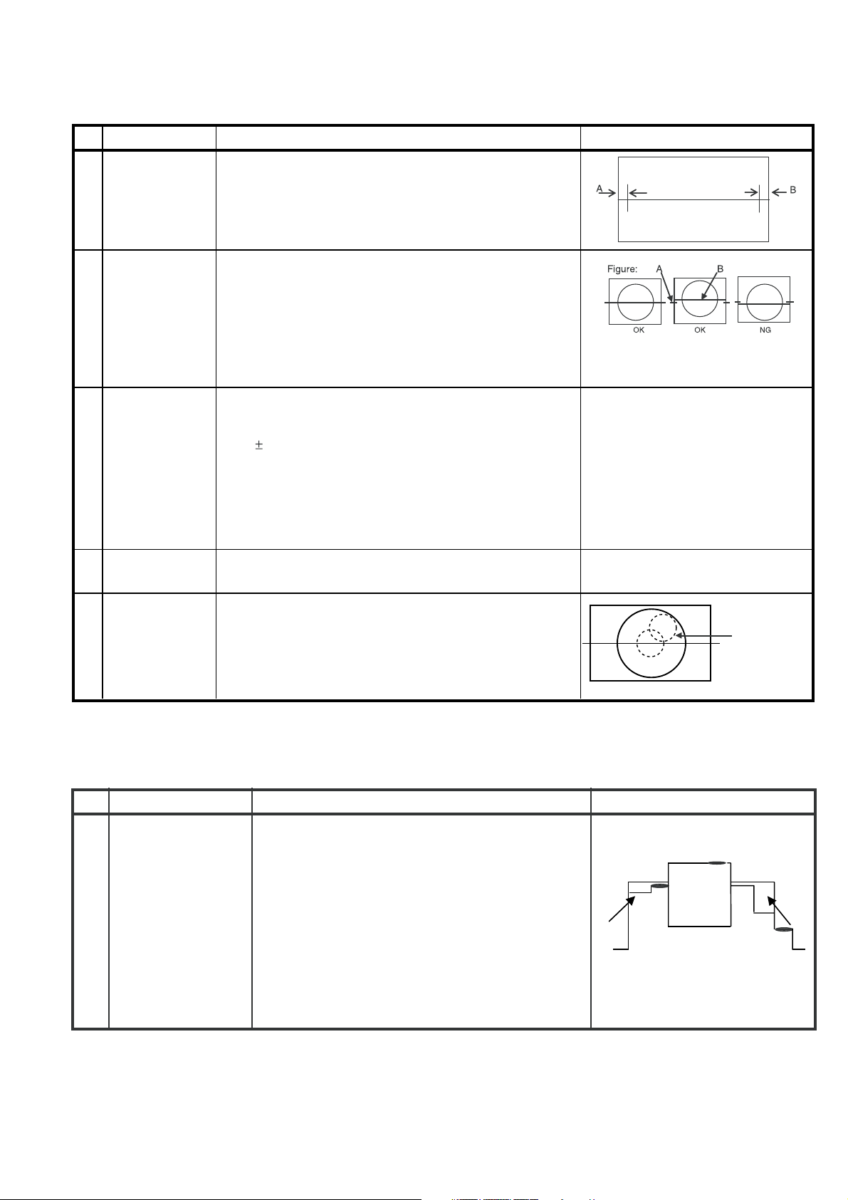
6. HORIZONTAL, VERTICAL, DEFLECTION LOOP and FOCUS ADJUSTMENT
No.
Adjustment point
H-SHIFT
1
2
C BUS
(I
CONTROL)
(to be done
after purity adj)
V-SHIFT
2
2
(I
C BUS
CONTROL)
(to be done
after purity adj)
1) Receive Monoscope Pattern Signal (PAL 50Hz).
2) Choose the service data V13.
3) Adjust the V13 bus data to have a balance position to
spec of A=B (as attach drawing).
4) If cannot make it to A=B, adjust from the best point so
that B slightly smaller than A.
1) Receive Monoscope Pattern Signal (PAL 50Hz).
2) Choose the service data V12.
3) Adjust the V12 bus data to have a most acceptable
vertical position, the monoscope pattern should be
Balance in vertical position.
Adjustment procedure/conditions Waveform and others
Note: B line (Monoscope middle line) must same or
nearest higher position to the A mark (Tube middle
mark), refer to the attach drawing.
V-SIZE
3
2
(I
C BUS
CONTROL)
(to be done
after purity,
1) Receive Monoscope Pattern Signal (PAL 50Hz).
2) Choose the service data V11.
3) Adjust V11 bus data until the overscan become
10 1.5%.
Caution 1: Pls aging TV more than 10 minutes before
V-shift adj)
Caution 2: for H-shift & V-shift & V-size adj, after adj
pls switch to Monoscope pattern signal (NTSC 60 Hz)
to confirm all positions are the same.
4
SUB-
1) Confirm Service data V08 & V32 are 38.
SHARPNESS
5
FOCUS
1) Receive the "Monoscope Pattern" signal.
2)
Press R/C to set Picture NORMAL condition.
3) Adjust the focus control to get the best focusing.
7. PAL CHROMA ADJUSTMENT
No.
Adjustment point
adjustment
Focusing Point
(middle of center
and edge of
monoscope
pattern)
Adjustment procedure/conditions Waveform and others
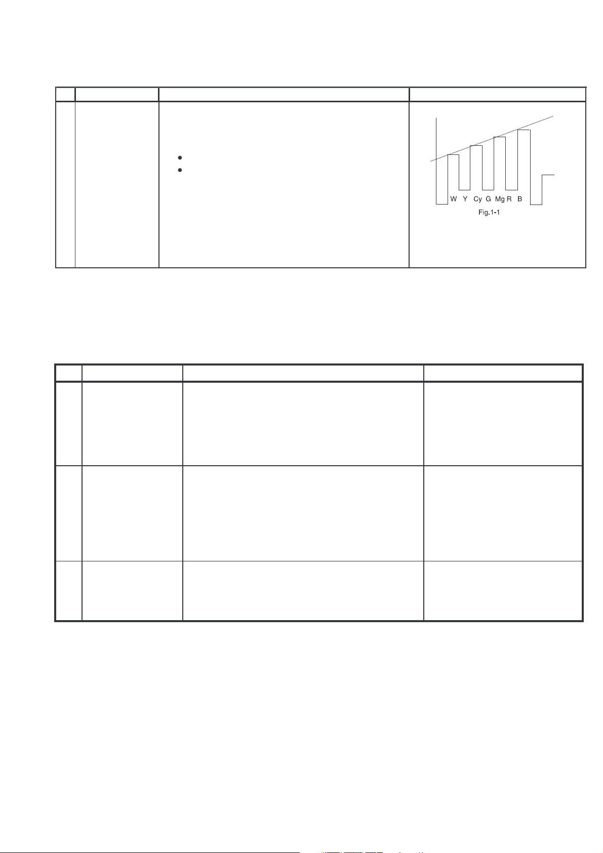
SUB COLOUR
1
2
(I
CONTROL)
(to be done
after subpicture, subtint adj)
C BUS
1) Receive the “PAL Colour Bar” signal.
2) Press R/C to set Picture Normal condition.
3) Connect the oscilloscope to R-Amp Transistor
Base(JUMPER 401).
Range : 100mV/Div (AC)
(Using 10:1 Probe)
Sweep Time : 10 msec/Div
4) Using the R/C call V05 in SERVICE mode. Adjust V05 bus data, so that the 75% White & Red
portions of PAL Colour Bar be at the same level
shown as Fig 1-1.
5) Clear the SERVICE mode.
3 – 20
75%
Cy G B
Y 100% W Mg R
W
Fig. 1-1
Page 24
8. NTSC CHROMA ADJUSTMENT
No.
Adjustment point
SUB-TINT
1
(I
CONTROL)
2
CBUS
1) Receive the "NTSC 3.58 Color Bar" signal thru
AV in.
2) Connect the oscilloscope to B-Amp Transistor
Base (JUMPER 410).
Range : 100mV/Div.(AC)(Use Probe 10:1)
Sweep time : 10 µsec/Div.
3) In Service mode, go to V07,pressR/C Y-mute
(Hex F4) or FLASHBACK Key.
4) Call the "V07" data in service mode. Adjust the
"V07" bus data to obtain the waveform shown as
Fig. 1-1.
5) Disable Y-Mute by pressing key (Hex E4) or
FLASHBACK, then clear the SERVICE mode.
21F-PD250 / 21F-PT220 / 21F-PA18 / 21F-PA18(B)
Adjustment procedure/conditions Waveform and others
9. PROTECTOR OPERATION CHECKING
No.
Adjustment point
BEAM 1) Receive "Monoscope Pattern" signal.
1 * Select one of Q853/4/5 to do
PROTECTOR
2) Set CONTRAST MAX.
Adjustment procedure/conditions Waveform and others
each short.
3) Set BRIGHT MAX.
4) During the Collector & Emitter of Q853/4/5 short,
make sure the protector ON and switch to standby
mode.
H, V PROTECTOR 1) Receive "Monoscope Pattern" signal.
2
2) Connect output of Bias Box to D602 cathode
(C602 positive).
3) Set voltage of Bias Box to 18V and make sure
the protector is not working.
4) Set voltage of Bias Box to 27V , and make sure
the protector is working.
3
OTHER
PROTECTOR
1) Once finish rectified Electrolytic Capacitor short
testing in +B line, check all possible damaged
components on +B line.
(Use random selected set for inspection)
3 – 21
Page 25

10. A/V INPUT, OUTPUT CHECKING
(2)
ADJUSTMENT POINT
NO
1 VIDEO AND AUDIO
OUTPUT CHECK
(1) Receive the "PAL Color Bar" signal (100% White Color Bar, Sound
400 Hz 100% Mod).
ADJUSTMENT CONDITION / PROCEDURE
21F-PD250 / 21F-PT220 / 21F-PA18 / 21F-PA18(B)
WAVEFORM OR OTHERS
2 VIDEO AND AUDIO
INPUT CHECK
(2) Terminate the Video output with a 75 ohm impedance. Make sure the output
is as specified
(3) Terminate the Audio output with a 10K ohm impedance. Make sure the O/P
is as specified
(1) Using the TV/VIDEO key on the remote controller, make sure that the modes
change in order of TV, AV1, AV2 & TV* again and the video & audio output
are according to the input terminal for each mode.
Video cross-talk AV to TV checking:
a) When connect AV1 input, check TV also
b) When connect AV2 input, check TV also (Model 21F-PT220 only)
(1.0 Vp-p ± 3 dB)
(1.5 Vp-p ± 3 dB)
.
.
11. FUNCTION OPERATION CHECKING (VIDEO AND AUDIO)
No.
Adjustment point
CONTRAST key 1) Receive "Monoscope Pattern" signal.
1
Adjustment procedure/conditions Waveform and others
2) Set MENU, then go into PICTURE mode to select CONTRAST.
3) Press Volume Up/Down key to check whether the
CONTRAST effect is OK or not.
2
COLOUR key
1) Receive "Colour Bar" signal.
2) Set MENU, then go into PICTURE mode to select COLOUR.
3) Press Volume Up/Down key to check whether the
COLOUR effect is OK or not.
*CAUTION :
- 21F-PA18, 21F-PA18(B), 21F-PD250
Change in order of TV is AV & TV
- 21F-PT220 Change in order of TV is
AV1, AV2 & TV
BRIGHTNESS key 1) Receive "Monoscope Pattern" signal.
3
2) Set MENU, then go into PICTURE mode to select BRIGHTNESS.
3) Press Volume Up/Down key to check whether the
BRIGHTNESSeffectisOKornot.
TINT key 1) Receive the "NTSC Colour Bar" signal thru AV in.
4
2) Set MENU, then go into PICTURE mode to select TINT.
3) Press Volume Up/Down key to check TINT, UP
for GREEN direction and DOWN for PURPLE direction whether is OK or not.
5
SHARPNESS
Key
1) Receive "Monoscope Pattern" signal.
2) Set MENU, then go into PICTURE mode to select SHARPNESS.
3) Press Volume Up/Down key to check whether
the SHARPNESS effect is OK or not.
6
CH DISPLAY
COLOUR
1) All Ch (0~99) will have an OSD display of the
channel number in green colour under AFT ON
condition.
3 – 22
Page 26
21F-PD250 / 21F-PT220 / 21F-PA18 / 21F-PA18(B)
No.
8
9
Adjustment point
NORMAL Key7
WHITE TEMP
COLOUR
SYSTEM
Adjustment procedure/conditions Waveform and others
Once in PICTURE Mode, and the NORMAL key is
1)
pressed, all the settings will be preset to normal setting
accordingly.
PICTURE MODE
CONTRAST 60
COLOUR +6
BRIGHTNESS 0
TINT CENTER
SHARPNESS +6
WHITE TEMP Mid
1) Receive "Monoscope Pattern" signal.
2) Set MENU, then go into PICTURE mode to se-
lect WHITE TEMP
3) Press Vo ume Up/Down key to check WHITE
TEMP function The back ground will change to
(shift right) bluish and (shift left) reddish.
Receive the "PAL COLOUR BAR" signal, press
1)
MENU, choose CH-SETTING to select COLOR
modes except PAL, check the COLOUR is not
working properly. Then, select the "PAL" mode.
Check again its colour so that it is working properly.
Receive "NTSC 4.43" signal, press MENU, choose
2)
CH-SETTING to select COLOR modes except
N443, check the COLOUR is not working properly.
Then, select the N443 mode. Check again its colour so that it is working properly.
Receive "NTSC 3.58" signal thru AV, press MENU,
3)
choose CH-SETTING to select COLOR modes except N358, check the COLOUR is not working
properly. Then, select the N358 mode. Check again
its colour so that it is working properly.
*
Note:
In NORMAL Mode, when
press NORMAL key, will appear NORMAL OSD and all
setting PICTURE function
set to NORMAL.
SOUND
10
SYSTEM
11 OSD
LANGUAGE
QUANTITY
CHECK
Receive "PAL-B/G" signal, press the “SOUND
1)
SYSTEM” to select D/K. Check the sound output
in not working proprely. Select B/G and check the
sound output to make sure it is working properly.
Receive "PAL-D/K" signal, press the “SOUND
2)
SYSTEM” to select B/G. Check the sound output
in not working proprely. Select D/K and check the
sound output to make sure it is working properly.
Check OSD LANGUAGE quantity and type for
1)
respect model.
MODEL
ALL MODEL 2 O O
QUANTITY ENGLISH THAI
3 – 23
Page 27

12. SHOCK TEST CHECKING
21F-PD250 / 21F-PT220 / 21F-PA18 / 21F-PA18(B)
No.
Adjustment point
SHOCK TEST 1) Hit at the top of TV set for two time.
1
Adjustment procedure/conditions Waveform and others
2) Check TV set not damage and TV operation operate correctly.
3 – 24
Page 28

CHAPTER 4. MEMORY MAP
[1] MEMORY MAP
21F-PD250 / 21F-PT220 / 21F-PA18 / 21F-PA18(B)
MODEL :
GA-7_IXC129WJN1
EEPROM CHECK DATA LIST 1
SEM PCD SOFTWARE GROUP TV DESIGN ENGINEERING TV PRODUCTION ENGINEERING
ISSUED DATE :1 MARCH 2007
MANAGER MANAGER MANAGER
CHIEF CHIEF CHIEF
ENGINEER
ISSUED DATE : ISSUED DATE : 28.JUNE.2007
ENGINEER ENGINEER
Tan
SLAVE ADDRESS : A0(00-FF) A2(100-1FF) A4(200-2FF) A6(300-3FF) A8(400-4FF) AA(500-5FF) AC(600-6FF) AE(700-7FF)
ADDRESS DATA MICON EEPROM EEPROM CHASSIS CTV FINAL
(HEX) D7 D6 D5 D4 D3 D2 D1 D0 DEFAULT RANGE
00
01
02
03
04
05
06
07
08
09
0A
0B
0C
0D
0E
0F
10
11
12
13
14
15
16
17
18
19
1A
1B
1C
1D
1E
1F
20
21
22
23
24
25
26
27
28
29
2A
2B
2C
2D
2E
2F
30
31
32
33
34
35
36
37
38
39
3A
3B
3C
3D
3E
3F
EEPROM INITIALIZATION JUDGEMENT BYTE-0
EEPROM INITIALIZATION JUDGEMENT BYTE-1
EEPROM INITIALIZATION JUDGEMENT BYTE-2
EEPROM INITIALIZATION JUDGEMENT BYTE-3
ROM VERSION
SOFTWARE VERSION (HIGH BYTE)
SOFTWARE VERSION (LOW BYTE)
TUNING FREQUENCY (LOW BYTE)
TUNING FREQUENCY (HIGH BYTE)
TUNING FREQUENCY (LOW BYTE)
TUNING FREQUENCY (HIGH BYTE)
TUNING FREQUENCY (LOW BYTE)
TUNING FREQUENCY (HIGH BYTE)
TUNING FREQUENCY (LOW BYTE)
TUNING FREQUENCY (HIGH BYTE)
TUNING FREQUENCY (LOW BYTE)
TUNING FREQUENCY (HIGH BYTE)
TUNING FREQUENCY (LOW BYTE)
TUNING FREQUENCY (HIGH BYTE)
TUNING FREQUENCY (LOW BYTE)
TUNING FREQUENCY (HIGH BYTE)
TUNING FREQUENCY (LOW BYTE)
TUNING FREQUENCY (HIGH BYTE)
TUNING FREQUENCY (LOW BYTE)
TUNING FREQUENCY (HIGH BYTE)
TUNING FREQUENCY (LOW BYTE)
TUNING FREQUENCY (HIGH BYTE)
TUNING FREQUENCY (LOW BYTE)
TUNING FREQUENCY (HIGH BYTE)
TUNING FREQUENCY (LOW BYTE)
TUNING FREQUENCY (HIGH BYTE)
TUNING FREQUENCY (LOW BYTE)
TUNING FREQUENCY (HIGH BYTE)
TUNING FREQUENCY (LOW BYTE)
TUNING FREQUENCY (HIGH BYTE)
TUNING FREQUENCY (LOW BYTE)
TUNING FREQUENCY (HIGH BYTE)
TUNING FREQUENCY (LOW BYTE)
TUNING FREQUENCY (HIGH BYTE)
TUNING FREQUENCY (LOW BYTE)
TUNING FREQUENCY (HIGH BYTE)
TUNING FREQUENCY (LOW BYTE)
TUNING FREQUENCY (HIGH BYTE)
TUNING FREQUENCY (LOW BYTE)
TUNING FREQUENCY (HIGH BYTE)
TUNING FREQUENCY (LOW BYTE)
TUNING FREQUENCY (HIGH BYTE)
TUNING FREQUENCY (LOW BYTE)
TUNING FREQUENCY (HIGH BYTE)
TUNING FREQUENCY (LOW BYTE)
TUNING FREQUENCY (HIGH BYTE)
TUNING FREQUENCY (LOW BYTE)
TUNING FREQUENCY (HIGH BYTE)
TUNING FREQUENCY (LOW BYTE)
TUNING FREQUENCY (HIGH BYTE)
TUNING FREQUENCY (LOW BYTE)
TUNING FREQUENCY (HIGH BYTE)
TUNING FREQUENCY (LOW BYTE)
TUNING FREQUENCY (HIGH BYTE)
TUNING FREQUENCY (LOW BYTE)
TUNING FREQUENCY (HIGH BYTE)
TUNING FREQUENCY (LOW BYTE)
TUNING FREQUENCY (HIGH BYTE)
7C 00-FF 7C
70 00-FF 70
79 00-FF 79
78 00-FF 78
00 00-FF 00
01 00-FF 01
00 00-FF 00
WRITE(CPU) CHECK DATA CHECK TYPE CHECK DATA CHECK TYPE
FF
00-FF FF
00-FF FF
00-FF 5B
00-FF 07
00-FF BB
00-FF 10
00-FF D3
00-FF 11
00-FF EB
00-FF 12
00-FF 03
00-FF 14
00-FF DB
00-FF 2C
00-FF 1B
00-FF 29
00-FF FB
00-FF 2F
00-FF DB
00-FF 31
00-FF 93
00-FF 33
00-FF CF
00-FF 06
00-FF E7
00-FF 07
00-FF 5F
00-FF 12
00-FF 77
00-FF 13
00-FF 8F
00-FF 14
00-FF DB
00-FF 27
00-FF DB
00-FF 45
00-FF FF
00-FF FF
00-FF FF
00-FF FF
00-FF FF
00-FF FF
00-FF 89
00-FF 14
00-FF 87
00-FF 14
00-FF 87
00-FF 14
00-FF 97
00-FF 14
00-FF 85
00-FF 14
00-FF 99
00-FF 14
00-FF FF
00-FF FF
MODEL MODEL
LAST INITIAL
SETTING DATA
MATSUNAGA
ISMAIL
CHIN
REMARK
* depend on
Ixcode,
current this
model ix
IXC080 so
set as 7C 70
78 70.
*depend on final
release version. If
version 0.70 so it
will become 00 & 46
POS 0
POS 1
POS 2
POS 3
POS 4
POS 5
POS 6
POS 7
POS 8
POS 9
POS 10
POS 11
POS 12
POS 13
POS 14
POS 15
POS 16
POS 17
POS 18
POS 19
POS 20
POS 21
POS 22
POS 23
POS 24
POS 25
POS 26
POS 27
LETTER NO. LETTER NO.
4 – 1
Page 29

MEMORY MAP (Continued)
21F-PD250 / 21F-PT220 / 21F-PA18 / 21F-PA18(B)
MODEL :
GA-7_IXC129WJN1
EEPROM CHECK DATA LIST 2
SEM PCD SOFTWARE GROUP TV DESIGN ENGINEERING TV PRODUCTION ENGINEERING
ISSUED DATE :1 MARCH 2007 ISSUED DATE : ISSUED DATE : 28.JUNE.2007
MANAGER MANAGER MANAGER
CHIEF CHIEF CHIEF
ENGINEER
ENGINEER ENGINEER
Tan
SLAVE ADDRESS : A0(00-FF) A2(100-1FF) A4(200-2FF) A6(300-3FF) A8(400-4FF) AA(500-5FF) AC(600-6FF) AE(700-7FF)
ADDRESS DATA MICON EEPROM EEPROM CHASSIS CTV FINAL
(HEX)D7D6D5D4D3D2D1D0DEFAULT RANGE
40
41
42
43
44
45
46
47
48
49
4A
4B
4C
4D
4E
4F
50
51
52
53
54
55
56
57
58
59
5A
5B
5C
5D
5E
5F
60
61
62
63
64
65
66
67
68
69
6A
6B
6C
6D
6E
6F
70
71
72
73
74
75
76
77
78
79
7A
7B
7C
7D
7E
7F
TUNING FREQUENCY (LOW BYTE)
TUNING FREQUENCY (HIGH BYTE)
TUNING FREQUENCY (LOW BYTE)
TUNING FREQUENCY (HIGH BYTE)
TUNING FREQUENCY (LOW BYTE)
TUNING FREQUENCY (HIGH BYTE)
TUNING FREQUENCY (LOW BYTE)
TUNING FREQUENCY (HIGH BYTE)
TUNING FREQUENCY (LOW BYTE)
TUNING FREQUENCY (HIGH BYTE)
TUNING FREQUENCY (LOW BYTE)
TUNING FREQUENCY (HIGH BYTE)
TUNING FREQUENCY (LOW BYTE)
TUNING FREQUENCY (HIGH BYTE)
TUNING FREQUENCY (LOW BYTE)
TUNING FREQUENCY (HIGH BYTE)
TUNING FREQUENCY (LOW BYTE)
TUNING FREQUENCY (HIGH BYTE)
TUNING FREQUENCY (LOW BYTE)
TUNING FREQUENCY (HIGH BYTE)
TUNING FREQUENCY (LOW BYTE)
TUNING FREQUENCY (HIGH BYTE)
TUNING FREQUENCY (LOW BYTE)
TUNING FREQUENCY (HIGH BYTE)
TUNING FREQUENCY (LOW BYTE)
TUNING FREQUENCY (HIGH BYTE)
TUNING FREQUENCY (LOW BYTE)
TUNING FREQUENCY (HIGH BYTE)
TUNING FREQUENCY (LOW BYTE)
TUNING FREQUENCY (HIGH BYTE)
TUNING FREQUENCY (LOW BYTE)
TUNING FREQUENCY (HIGH BYTE)
TUNING FREQUENCY (LOW BYTE)
TUNING FREQUENCY (HIGH BYTE)
TUNING FREQUENCY (LOW BYTE)
TUNING FREQUENCY (HIGH BYTE)
TUNING FREQUENCY (LOW BYTE)
TUNING FREQUENCY (HIGH BYTE)
TUNING FREQUENCY (LOW BYTE)
TUNING FREQUENCY (HIGH BYTE)
TUNING FREQUENCY (LOW BYTE)
TUNING FREQUENCY (HIGH BYTE)
TUNING FREQUENCY (LOW BYTE)
TUNING FREQUENCY (HIGH BYTE)
TUNING FREQUENCY (LOW BYTE)
TUNING FREQUENCY (HIGH BYTE)
TUNING FREQUENCY (LOW BYTE)
TUNING FREQUENCY (HIGH BYTE)
TUNING FREQUENCY (LOW BYTE)
TUNING FREQUENCY (HIGH BYTE)
TUNING FREQUENCY (LOW BYTE)
TUNING FREQUENCY (HIGH BYTE)
TUNING FREQUENCY (LOW BYTE)
TUNING FREQUENCY (HIGH BYTE)
TUNING FREQUENCY (LOW BYTE)
TUNING FREQUENCY (HIGH BYTE)
TUNING FREQUENCY (LOW BYTE)
TUNING FREQUENCY (HIGH BYTE)
TUNING FREQUENCY (LOW BYTE)
TUNING FREQUENCY (HIGH BYTE)
TUNING FREQUENCY (LOW BYTE)
TUNING FREQUENCY (HIGH BYTE)
TUNING FREQUENCY (LOW BYTE)
TUNING FREQUENCY (HIGH BYTE)
WRITE(CPU) CHECK DATA CHECK TYPE CHECK DATA CHECK TYPE
00-FF FF
00-FF FF
00-FF FF
00-FF FF
00-FF FF
00-FF FF
00-FF 2B
00-FF 0A
00-FF 1B
00-FF 0B
00-FF 6B
00-FF 10
00-FF 5B
00-FF 11
00-FF 23
00-FF 12
00-FF 13
00-FF 13
00-FF 03
00-FF 14
00-FF 93
00-FF 33
00-FF FF
00-FF FF
00-FF FF
00-FF FF
00-FF FF
00-FF FF
00-FF FF
00-FF FF
00-FF FF
00-FF FF
00-FF FF
00-FF FF
00-FF FF
00-FF FF
00-FF FF
00-FF FF
00-FF FF
00-FF FF
00-FF FF
00-FF FF
00-FF FF
00-FF FF
00-FF FF
00-FF FF
00-FF FF
00-FF FF
00-FF FF
00-FF FF
00-FF FF
00-FF FF
00-FF FF
00-FF FF
00-FF FF
00-FF FF
00-FF FF
00-FF FF
00-FF FF
00-FF FF
00-FF FF
00-FF FF
00-FF FF
00-FF FF
MODEL MODEL
MATSUNAGA
ISMAIL
CHIN
LAST INITIAL
SETTING DATA REMARK
POS 28
POS 29
POS 30
POS 31
POS 32
POS 33
POS 34
POS 35
POS 36
POS 37
POS 38
POS 39
POS 40
POS 41
POS 42
POS 43
POS 44
POS 45
POS 46
POS 47
POS 48
POS 49
POS 50
POS 51
POS 52
POS 53
POS 54
POS 55
POS 56
POS 57
POS 58
POS 59
LETTER NO. LETTER NO.
4 – 2
Page 30

MEMORY MAP (Continued)
21F-PD250 / 21F-PT220 / 21F-PA18 / 21F-PA18(B)
MODEL :
GA-7_IXC129WJN1
EEPROM CHECK DATA LIST 3
SEM PCD SOFTWARE GROUP TV DESIGN ENGINEERING TV PRODUCTION ENGINEERING
ISSUED DATE :1 MARCH 2007 ISSUED DATE : ISSUED DATE : 28.JUNE.2007
MANAGER MANAGER MANAGER
CHIEF CHIEF CHIEF
ENGINEER
ENGINEER ENGINEER
Tan
SLAVE ADDRESS : A0(00-FF) A2(100-1FF) A4(200-2FF) A6(300-3FF) A8(400-4FF) AA(500-5FF) AC(600-6FF) AE(700-7FF)
ADDRESS
(HEX)D7D6D5D4D3D2D1D0
80
81
82
83
84
85
86
87
88
89
8A
8B
8C
8D
8E
8F
90
91
92
93
94
95
96
97
98
99
9A
9B
9C
9D
9E
9F
A0
A1
A2
A3
A4
A5
A6
A7
A8
A9
AA
AB
AC
AD
AE
AF
B0
B1
B2
B3
B4
B5
B6
B7
B8
B9
BA
BB
BC
BD
BE
BF
DATA
TUNING FREQUENCY (LOW BYTE)
TUNING FREQUENCY (HIGH BYTE)
TUNING FREQUENCY (LOW BYTE)
TUNING FREQUENCY (HIGH BYTE)
TUNING FREQUENCY (LOW BYTE)
TUNING FREQUENCY (HIGH BYTE)
TUNING FREQUENCY (LOW BYTE)
TUNING FREQUENCY (HIGH BYTE)
TUNING FREQUENCY (LOW BYTE)
TUNING FREQUENCY (HIGH BYTE)
TUNING FREQUENCY (LOW BYTE)
TUNING FREQUENCY (HIGH BYTE)
TUNING FREQUENCY (LOW BYTE)
TUNING FREQUENCY (HIGH BYTE)
TUNING FREQUENCY (LOW BYTE)
TUNING FREQUENCY (HIGH BYTE)
TUNING FREQUENCY (LOW BYTE)
TUNING FREQUENCY (HIGH BYTE)
TUNING FREQUENCY (LOW BYTE)
TUNING FREQUENCY (HIGH BYTE)
TUNING FREQUENCY (LOW BYTE)
TUNING FREQUENCY (HIGH BYTE)
TUNING FREQUENCY (LOW BYTE)
TUNING FREQUENCY (HIGH BYTE)
TUNING FREQUENCY (LOW BYTE)
TUNING FREQUENCY (HIGH BYTE)
TUNING FREQUENCY (LOW BYTE)
TUNING FREQUENCY (HIGH BYTE)
TUNING FREQUENCY (LOW BYTE)
TUNING FREQUENCY (HIGH BYTE)
TUNING FREQUENCY (LOW BYTE)
TUNING FREQUENCY (HIGH BYTE)
TUNING FREQUENCY (LOW BYTE)
TUNING FREQUENCY (HIGH BYTE)
TUNING FREQUENCY (LOW BYTE)
TUNING FREQUENCY (HIGH BYTE)
TUNING FREQUENCY (LOW BYTE)
TUNING FREQUENCY (HIGH BYTE)
TUNING FREQUENCY (LOW BYTE)
TUNING FREQUENCY (HIGH BYTE)
TUNING FREQUENCY (LOW BYTE)
TUNING FREQUENCY (HIGH BYTE)
TUNING FREQUENCY (LOW BYTE)
TUNING FREQUENCY (HIGH BYTE)
TUNING FREQUENCY (LOW BYTE)
TUNING FREQUENCY (HIGH BYTE)
TUNING FREQUENCY (LOW BYTE)
TUNING FREQUENCY (HIGH BYTE)
TUNING FREQUENCY (LOW BYTE)
TUNING FREQUENCY (HIGH BYTE)
TUNING FREQUENCY (LOW BYTE)
TUNING FREQUENCY (HIGH BYTE)
TUNING FREQUENCY (LOW BYTE)
TUNING FREQUENCY (HIGH BYTE)
TUNING FREQUENCY (LOW BYTE)
TUNING FREQUENCY (HIGH BYTE)
TUNING FREQUENCY (LOW BYTE)
TUNING FREQUENCY (HIGH BYTE)
TUNING FREQUENCY (LOW BYTE)
TUNING FREQUENCY (HIGH BYTE)
TUNING FREQUENCY (LOW BYTE)
TUNING FREQUENCY (HIGH BYTE)
TUNING FREQUENCY (LOW BYTE)
TUNING FREQUENCY (HIGH BYTE)
MICON EEPROM EEPROM CHASSIS CTV FINAL
DEFAULT RANGE
WRITE(CPU) CHECK DATA CHECK TYPE CHECK DATA CHECK TYPE
00-FF FF
00-FF FF
00-FF FF
00-FF FF
00-FF FF
00-FF FF
00-FF FF
00-FF FF
00-FF FF
00-FF FF
00-FF FF
00-FF FF
00-FF FF
00-FF FF
00-FF FF
00-FF FF
00-FF FF
00-FF FF
00-FF FF
00-FF FF
00-FF FF
00-FF FF
00-FF FF
00-FF FF
00-FF FF
00-FF FF
00-FF FF
00-FF FF
00-FF FF
00-FF FF
00-FF FF
00-FF FF
00-FF FF
00-FF FF
00-FF FF
00-FF FF
00-FF FF
00-FF FF
00-FF FF
00-FF FF
00-FF FF
00-FF FF
00-FF FF
00-FF FF
00-FF FF
00-FF FF
00-FF FF
00-FF FF
00-FF FF
00-FF FF
00-FF FF
00-FF FF
00-FF FF
00-FF FF
00-FF FF
00-FF FF
00-FF FF
00-FF FF
00-FF FF
00-FF FF
00-FF FF
00-FF FF
00-FF FF
00-FF FF
MODEL MODEL
LAST INITIAL
SETTING DATA
MATSUNAGA
ISMAIL
CHIN
REMARK
POS 60
POS 61
POS 62
POS 63
POS 64
POS 65
POS 66
POS 67
POS 68
POS 69
POS 70
POS 71
POS 72
POS 73
POS 74
POS 75
POS 76
POS 77
POS 78
POS 79
POS 80
POS 81
POS 82
POS 83
POS 84
POS 85
POS 86
POS 87
POS 88
POS 89
POS 90
POS 91
LETTER NO. LETTER NO.
4 – 3
Page 31

MEMORY MAP (Continued)
21F-PD250 / 21F-PT220 / 21F-PA18 / 21F-PA18(B)
MODEL :
GA-7_IXC129WJN1
EEPROM CHECK DATA LIST 4
SEM PCD SOFTWARE GROUP TV DESIGN ENGINEERING TV PRODUCTION ENGINEERING
ISSUED DATE :1 MARCH 2007 ISSUED DATE : ISSUED DATE : 28.JUNE.2007
MANAGER MANAGER MANAGER
CHIEF CHIEF CHIEF
ENGINEER
ENGINEER ENGINEER
Tan
SLAVE ADDRESS : A0(00-FF) A2(100-1FF) A4(200-2FF) A6(300-3FF) A8(400-4FF) AA(500-5FF) AC(600-6FF) AE(700-7FF)
ADDRESS DATA MICON EEPROM EEPROM CHASSIS CTV FINAL
(HEX)D7D6D5D4D3D2D1D0DEFAULT RANGE
C0
C1
C2
C3
C4
C5
C6
C7
C8
C9
CA
CB
CC
CD
CE
CF
D0
D1
D2
D3
D4
D5
D6
D7
D8
D9
DA
TUNING FREQUENCY (LOW BYTE)
TUNING FREQUENCY (HIGH BYTE)
TUNING FREQUENCY (LOW BYTE)
TUNING FREQUENCY (HIGH BYTE)
TUNING FREQUENCY (LOW BYTE)
TUNING FREQUENCY (HIGH BYTE)
TUNING FREQUENCY (LOW BYTE)
TUNING FREQUENCY (HIGH BYTE)
TUNING FREQUENCY (LOW BYTE)
TUNING FREQUENCY (HIGH BYTE)
TUNING FREQUENCY (LOW BYTE)
TUNING FREQUENCY (HIGH BYTE)
TUNING FREQUENCY (LOW BYTE)
TUNING FREQUENCY (HIGH BYTE)
TUNING FREQUENCY (LOW BYTE)
TUNING FREQUENCY (HIGH BYTE)
FAVORITE CHANNEL 1
FAVORITE CHANNEL 2
FAVORITE CHANNEL 3
FAVORITE CHANNEL 4
CHILD LOCK PASSWORD 1
CHILD LOCK PASSWORD 2
CHILD LOCK PASSWORD 3
CHILD LOCK PASSWORD 4
AV MODE
LOCK TV
MP-IN
0A
14
1E
28
00 00-09 00
00 00-09 00
00 00-09 00
00 00-09 00
00 00-01 00
01 00-01 01
00 00-02 00
WRITE(CPU) CHECK DATA CHECK TYPE CHECK DATA CHECK TYPE
00-FF FF
00-FF FF
00-FF FF
00-FF FF
00-FF FF
00-FF FF
00-FF FF
00-FF FF
00-FF FF
00-FF FF
00-FF FF
00-FF FF
00-FF FF
00-FF FF
00-FF FF
00-FF FF
0A
00-FB
14
00-FB
1E
00-FB
28
00-FB
DB
DC
DD
DE
DF
POS 7 POS 6 POS 5 POS4 POS 3 POS 2 POS 1 POS 0
E0
POS15 POS14 POS13 POS12 POS11 POS10 POS 9 POS 8
E1
POS23 POS22 POS21 POS20 POS19 POS18 POS17 POS16
E2
POS31 POS30 POS29 POS28 POS27 POS26 POS25 POS24
E3
POS39 POS38 POS37 POS36 POS35 POS34 POS33 POS32
E4
POS47 POS46 POS45 POS44 POS43 POS42 POS41 POS40
E5
POS55 POS54 POS53 POS52 POS51 POS50 POS49 POS48
E6
POS63 POS62 POS61 POS60 POS59 POS58 POS57 POS56
E7
POS71 POS70 POS69 POS68 POS67 POS66 POS65 POS64
E8
POS79 POS78 POS77 POS76 POS75 POS74 POS73 POS72
E9
POS87 POS86 POS85 POS84 POS83 POS82 POS81 POS80
EA
POS95 POS94 POS93 POS92 POS91 POS90 POS89 POS88
EB
POS103 POS102 POS101 POS100 POS99 POS98 POS97 POS96
EC
ED
Blue Back
EE
EF
POS 7 POS 6 POS 5 POS4 POS 3 POS 2 POS 1 POS 0
F0
POS15 POS14 POS13 POS12 POS11 POS10 POS 9 POS 8
F1
POS23 POS22 POS21 POS20 POS19 POS18 POS17 POS16
F2
POS31 POS30 POS29 POS28 POS27 POS26 POS25 POS24
F3
POS39 POS38 POS37 POS36 POS35 POS34 POS33 POS32
F4
POS47 POS46 POS45 POS44 POS43 POS42 POS41 POS40
F5
POS55 POS54 POS53 POS52 POS51 POS50 POS49 POS48
F6
POS63 POS62 POS61 POS60 POS59 POS58 POS57 POS56
F7
POS71 POS70 POS69 POS68 POS67 POS66 POS65 POS64
F8
POS79 POS78 POS77 POS76 POS75 POS74 POS73 POS72
F9
POS87 POS86 POS85 POS84 POS83 POS82 POS81 POS80
FA
POS95 POS94 POS93 POS92 POS91 POS90 POS89 POS88
FB
POS103 POS102 POS101 POS100 POS99 POS98 POS97 POS96
FC
FD
FE
1/2/3 DIGIT ENTRY
TEXT (Not Use) LANGUAGE
LAST VOLUME
POWER
08 00-18 EF
FF
00-FF
FF
00-FF
FF
00-FF
FF
00-FF
FF
00-FF
FF
00-FF
FF
00-FF
FF
00-FF
FF
00-FF
FF
00-FF
FF
00-FF
FF
00-FF
FF
00-0F
00
00-FF
00 00-3C 3C
01
00-FF
00
00-FF
00
00-FF
00
00-FF
00
00-FF
00
00-FF
00
00-FF
00
00-FF
00
00-FF
00
00-FF
00
00-FF
00
00-FF
00
00-0F
AA(On),
AA
55(Off)
FF
FF
FF
FF
FF
FF
FF
FF
FF
FF
FF
FF
FF
00
01
00
00
00
00
00
00
00
00
00
00
00
00
AA
FF
MODEL MODEL
LAST INITIAL
SETTING DATA
MATSUNAGA
ISMAIL
CHIN
REMARK
POS 92
POS 93
POS 94
POS 95
POS 96
POS 97
POS 98
POS 99
POS 10
POS 20
POS 30
POS 40
1= AFT ON,
0=AFT OFF
1= SKIP ON,
0=SKIP OFF
LETTER NO. LETTER NO.
4 – 4
Page 32

MEMORY MAP (Continued)
21F-PD250 / 21F-PT220 / 21F-PA18 / 21F-PA18(B)
MODEL :
GA-7_IXC129WJN1
EEPROM CHECK DATA LIST 5
SEM PCD SOFTWARE GROUP TV DESIGN ENGINEERING TV PRODUCTION ENGINEERING
ISSUED DATE :1 MARCH 2007 ISSUED DATE : ISSUED DATE : 28.JUNE.2007
MANAGER MANAGER MANAGER
CHIEF CHIEF CHIEF
ENGINEER
ENGINEER ENGINEER
Tan
SLAVE ADDRESS : A0(00-FF) A2(100-1FF) A4(200-2FF) A6(300-3FF) A8(400-4FF) AA(500-5FF) AC(600-6FF) AE(700-7FF)
ADDRESS DATA MICON EEPROM EEPROM CHASSIS CTV FINAL
(HEX)D7D6D5D4D3D2D1D0DEFAULT RANGE
100
ANT-BOOSTER (POS0)
101
ANT-BOOSTER (POS1)
102
ANT-BOOSTER (POS2)
103
ANT-BOOSTER (POS3)
ANT-BOOSTER (POS4)
104
105
ANT-BOOSTER (POS5)
106
ANT-BOOSTER (POS6)
107
ANT-BOOSTER (POS7)
108
ANT-BOOSTER (POS8)
109
ANT-BOOSTER (POS9)
ANT-BOOSTER (POS10)
10A
ANT-BOOSTER (POS11)
10B
10C
ANT-BOOSTER (POS12)
ANT-BOOSTER (POS13)
10D
10E
ANT-BOOSTER (POS14)
ANT-BOOSTER (POS15)
10F
110
ANT-BOOSTER (POS16)
ANT-BOOSTER (POS17)
111
112
ANT-BOOSTER (POS18)
ANT-BOOSTER (POS19)
113
ANT-BOOSTER (POS20)
114
ANT-BOOSTER (POS21)
115
ANT-BOOSTER (POS22)
116
ANT-BOOSTER (POS23)
117
118
ANT-BOOSTER (POS24)
ANT-BOOSTER (POS25)
119
ANT-BOOSTER (POS26)
11A
ANT-BOOSTER (POS27)
11B
ANT-BOOSTER (POS28)
11C
11D
ANT-BOOSTER (POS29)
ANT-BOOSTER (POS30)
11E
ANT-BOOSTER (POS31)
11F
ANT-BOOSTER (POS32)
120
ANT-BOOSTER (POS33)
121
ANT-BOOSTER (POS34)
122
ANT-BOOSTER (POS35)
123
ANT-BOOSTER (POS36)
124
ANT-BOOSTER (POS37)
125
ANT-BOOSTER (POS38)
126
ANT-BOOSTER (POS39)
127
ANT-BOOSTER (POS40)
128
ANT-BOOSTER (POS41)
129
ANT-BOOSTER (POS42)
12A
ANT-BOOSTER (POS43)
12B
ANT-BOOSTER (POS44)
12C
ANT-BOOSTER (POS45)
12D
ANT-BOOSTER (POS46)
12E
ANT-BOOSTER (POS47)
12F
ANT-BOOSTER (POS48)
130
ANT-BOOSTER (POS49)
131
ANT-BOOSTER (POS50)
132
ANT-BOOSTER (POS51)
133
ANT-BOOSTER (POS52)
134
ANT-BOOSTER (POS53)
135
ANT-BOOSTER (POS54)
136
ANT-BOOSTER (POS55)
137
ANT-BOOSTER (POS56)
138
ANT-BOOSTER (POS57)
139
ANT-BOOSTER (POS58)
13A
ANT-BOOSTER (POS59)
13B
ANT-BOOSTER (POS60)
13C
ANT-BOOSTER (POS61)
13D
ANT-BOOSTER (POS62)
13E
ANT-BOOSTER (POS63)
13F
S-SYSTEM (POS0)
S-SYSTEM (POS1)
S-SYSTEM (POS2)
S-SYSTEM (POS3)
S-SYSTEM (POS4) C-SYSTEM (POS4)
S-SYSTEM (POS5) C-SYSTEM (POS5)
S-SYSTEM (POS6) C-SYSTEM (POS6)
S-SYSTEM (POS7) C-SYSTEM POS7)
S-SYSTEM (POS8) C-SYSTEM (POS8)
S-SYSTEM (POS9) C-SYSTEM (POS9)
S-SYSTEM (POS10) C-SYSTEM (POS10)
S-SYSTEM (POS11)
S-SYSTEM (POS12) C-SYSTEM (POS12)
S-SYSTEM (POS13) C-SYSTEM (POS13)
S-SYSTEM (POS14) C-SYSTEM (POS14)
S-SYSTEM (POS15) C-SYSTEM (POS15)
S-SYSTEM (POS16) C-SYSTEM (POS16)
S-SYSTEM (POS17) C-SYSTEM (POS17)
S-SYSTEM (POS18) C-SYSTEM (POS18)
S-SYSTEM (POS19)
S-SYSTEM (POS20) C-SYSTEM (POS20)
S-SYSTEM (POS21)
S-SYSTEM (POS22) C-SYSTEM (POS22)
S-SYSTEM (POS23) C-SYSTEM (POS23)
S-SYSTEM (POS24) C-SYSTEM (POS24)
S-SYSTEM (POS25) C-SYSTEM (POS25)
S-SYSTEM (POS26) C-SYSTEM (POS26)
S-SYSTEM (POS27) C-SYSTEM (POS27)
S-SYSTEM (POS28) C-SYSTEM (POS28)
S-SYSTEM (POS29)
S-SYSTEM (POS30)
S-SYSTEM (POS31)
S-SYSTEM (POS32)
S-SYSTEM (POS33) C-SYSTEM (POS33)
S-SYSTEM (POS34) C-SYSTEM (POS34)
S-SYSTEM (POS35) C-SYSTEM (POS35)
S-SYSTEM (POS36) C-SYSTEM (POS36)
S-SYSTEM (POS37) C-SYSTEM (POS37)
S-SYSTEM (POS38) C-SYSTEM (POS38)
S-SYSTEM (POS39) C-SYSTEM (POS39)
S-SYSTEM (POS40)
S-SYSTEM (POS41)
S-SYSTEM (POS42)
S-SYSTEM (POS43)
S-SYSTEM (POS44)
S-SYSTEM (POS45) C-SYSTEM (POS45)
S-SYSTEM (POS46) C-SYSTEM (POS46)
S-SYSTEM (POS47) C-SYSTEM (POS47)
S-SYSTEM (POS48) C-SYSTEM (POS48)
S-SYSTEM (POS49) C-SYSTEM (POS49)
S-SYSTEM (POS50) C-SYSTEM (POS50)
S-SYSTEM (POS51) C-SYSTEM (POS51)
S-SYSTEM (POS52) C-SYSTEM (POS52)
S-SYSTEM (POS53) C-SYSTEM (POS53)
S-SYSTEM (POS54) C-SYSTEM (POS54)
S-SYSTEM (POS55)
S-SYSTEM (POS56) C-SYSTEM (POS56)
S-SYSTEM (POS57) C-SYSTEM (POS57)
S-SYSTEM (POS58) C-SYSTEM (POS58)
S-SYSTEM (POS59) C-SYSTEM (POS59)
S-SYSTEM (POS60) C-SYSTEM (POS60)
S-SYSTEM (POS61)
S-SYSTEM (POS62)
S-SYSTEM (POS63)
C-SYSTEM (POS0)
C-SYSTEM (POS1)
C-SYSTEM (POS2)
C-SYSTEM (POS3)
C-SYSTEM (POS11)
C-SYSTEM (POS19)
C-SYSTEM (POS21)
C-SYSTEM (POS29)
C-SYSTEM (POS30)
C-SYSTEM (POS31)
C-SYSTEM (POS32)
C-SYSTEM (POS40)
C-SYSTEM (POS41)
C-SYSTEM (POS42)
C-SYSTEM (POS43)
C-SYSTEM (POS44)
C-SYSTEM (POS55)
C-SYSTEM (POS61)
C-SYSTEM (POS62)
C-SYSTEM (POS63)
00
00
00
00
00
00
00
00
00
00
00
00
00
00
00
00
00
00
00
00
00
00
00
00
00
00
00
00
00
00
00
00
00
00
00
00
00
00
00
00
00
00
00
00
00
00
00
00
00
00
00
00
00
00
00
00
00
00
00
00
00
00
00
00
WRITE(CPU) CHECK DATA CHECK TYPE CHECK DATA CHECK TYPE
00
00-9C
00
00-9C
00
00-9C
00
00-9C
00
00-9C
00
00-9C
00
00-9C
00
00-9C
00
00-9C
00
00-9C
00
00-9C
00
00-9C
00
00-9C
00
00-9C
00
00-9C
00
00-9C
00
00-9C
00
00-9C
00
00-9C
00
00-9C
00
00-9C
00
00-9C
00
00-9C
00
00-9C
00
00-9C
00
00-9C
00
00-9C
00
00-9C
00
00-9C
00
00-9C
00
00-9C
18
00-9C
18
00-9C
18
00-9C
18
00-9C
18
00-9C
18
00-9C
18
00-9C
18
00-9C
00
00-9C
00
00-9C
00
00-9C
00
00-9C
00
00-9C
00
00-9C
00
00-9C
00
00-9C
00
00-9C
00
00-9C
00
00-9C
00
00-9C
00
00-9C
00
00-9C
00
00-9C
00
00-9C
00
00-9C
00
00-9C
00
00-9C
00
00-9C
00
00-9C
00
00-9C
00
00-9C
00
00-9C
00
00-9C
MODEL MODEL
LAST INITIAL
SETTING DATA
MATSUNAGA
ISMAIL
CHIN
REMARK
S-SYSTEM
0: B/G
1: I
2: D/K
3: M
C-SYSTEM
0: AUTO
1: PAL
2:SECAM
3: N443
4:N358
ANT-BOOSTER
0: OFF
1: ON I
2: ON II
LETTER NO. LETTER NO.
4 – 5
Page 33

MEMORY MAP (Continued)
21F-PD250 / 21F-PT220 / 21F-PA18 / 21F-PA18(B)
MODEL :
GA-7_IXC129WJN1
EEPROM CHECK DATA LIST 6
SEM PCD SOFTWARE GROUP TV DESIGN ENGINEERING TV PRODUCTION ENGINEERING
ISSUED DATE :1 MARCH 2007 ISSUED DATE : ISSUED DATE : 28.JUNE.2007
MANAGER MANAGER MANAGER
CHIEF CHIEF CHIEF
ENGINEER
ENGINEER ENGINEER
Tan
SLAVE ADDRESS : A0(00-FF) A2(100-1FF) A4(200-2FF) A6(300-3FF) A8(400-4FF) AA(500-5FF) AC(600-6FF) AE(700-7FF)
ADDRESS
(HEX)D7D6D5D4D3D2D1D0
140 ANT-BOOSTER (POS64)
141 ANT-BOOSTER (POS65)
142 ANT-BOOSTER (POS66)
143 ANT-BOOSTER (POS67)
144 ANT-BOOSTER (POS68)
145 ANT-BOOSTER (POS69)
146 ANT-BOOSTER (POS70)
147 ANT-BOOSTER (POS71)
148 ANT-BOOSTER (POS72)
149 ANT-BOOSTER (POS73)
14A
ANT-BOOSTER (POS74)
14B
ANT-BOOSTER (POS75)
14C
ANT-BOOSTER (POS76)
14D
ANT-BOOSTER (POS77)
14E
ANT-BOOSTER (POS78)
14F
ANT-BOOSTER (POS79)
150
ANT-BOOSTER (POS80)
151
ANT-BOOSTER (POS81)
152
ANT-BOOSTER (POS82)
153
ANT-BOOSTER (POS83)
154
ANT-BOOSTER (POS84)
155
ANT-BOOSTER (POS85)
156
ANT-BOOSTER (POS86)
157
ANT-BOOSTER (POS87)
158
ANT-BOOSTER (POS88)
159
ANT-BOOSTER (POS89)
15A
ANT-BOOSTER (POS90)
15B
ANT-BOOSTER (POS91)
15C
ANT-BOOSTER (POS92)
15D
ANT-BOOSTER (POS93)
15E
ANT-BOOSTER (POS94)
15F
ANT-BOOSTER (POS95)
160
ANT-BOOSTER (POS96)
161
ANT-BOOSTER (POS97)
162
ANT-BOOSTER (POS98)
163
ANT-BOOSTER (POS99)
164
C-SYSTEM (AV2) C-SYSTEM (AV1)
165
166
167
168
169
16A
16B
16C
16D
16E
16F
170
171
172
173
174
175
176
177
178
179
17A
17B
17C
17D
17E
17F
DATA
S-SYSTEM (POS64) C-SYSTEM (POS64)
S-SYSTEM (POS65) C-SYSTEM (POS65)
S-SYSTEM (POS66) C-SYSTEM (POS66)
S-SYSTEM (POS67) C-SYSTEM (POS67)
S-SYSTEM (POS68) C-SYSTEM (POS68)
S-SYSTEM (POS69) C-SYSTEM (POS69)
S-SYSTEM (POS70) C-SYSTEM (POS70)
S-SYSTEM (POS71) C-SYSTEM POS71)
S-SYSTEM (POS72) C-SYSTEM (POS72)
S-SYSTEM (POS73) C-SYSTEM (POS73)
S-SYSTEM (POS74) C-SYSTEM (POS74)
S-SYSTEM (POS75) C-SYSTEM (POS75)
S-SYSTEM (POS76) C-SYSTEM (POS76)
S-SYSTEM (POS77) C-SYSTEM (POS77)
S-SYSTEM (POS78) C-SYSTEM (POS78)
S-SYSTEM (POS79)
S-SYSTEM (POS80) C-SYSTEM (POS80)
S-SYSTEM (POS81) C-SYSTEM (POS81)
S-SYSTEM (POS82) C-SYSTEM (POS82)
S-SYSTEM (POS83) C-SYSTEM (POS83)
S-SYSTEM (POS84) C-SYSTEM (POS84)
S-SYSTEM (POS85) C-SYSTEM (POS85)
S-SYSTEM (POS86) C-SYSTEM (POS86)
S-SYSTEM (POS87) C-SYSTEM (POS87)
S-SYSTEM (POS88) C-SYSTEM (POS88)
S-SYSTEM (POS89) C-SYSTEM (POS89)
S-SYSTEM (POS90) C-SYSTEM (POS90)
S-SYSTEM (POS91) C-SYSTEM (POS91)
S-SYSTEM (POS92) C-SYSTEM (POS92)
S-SYSTEM (POS93) C-SYSTEM (POS93)
S-SYSTEM (POS94) C-SYSTEM (POS94)
S-SYSTEM (POS95) C-SYSTEM (POS95)
S-SYSTEM (POS96) C-SYSTEM (POS96)
S-SYSTEM (POS97) C-SYSTEM (POS97)
S-SYSTEM (POS98) C-SYSTEM (POS98)
S-SYSTEM (POS99) C-SYSTEM (POS99)
SLV1 (HIGH)
SLV1 (LOW)
SLV2 (HIGH)
SLV2 (LOW)
SLV3 (HIGH)
SLV3 (LOW)
SLV4 (HIGH)
SLV4 (LOW)
SLV5 (HIGH)
SLV5 (LOW)
SLV6 (HIGH)
SLV6 (LOW)
SLV7 (HIGH)
SLV7 (LOW)
LAST CHANNEL POSITION
FLASH BACK POSITION
ROM CORRECTION-1 ID
ROM CORRECTION-1 HIGH BYTE ADDRESS
ROM CORRECTION-1 LOW BYTE ADDRESS
ROM CORRECTION-1 DATA LENGTH
ROM CORRECTION-1 CHECKSUM
ROM CORRECTION-2 ID
ROM CORRECTION-2 HIGH BYTE ADDRESS
ROM CORRECTION-2 LOW BYTE ADDRESS
ROM CORRECTION-2 DATA LENGTH
ROM CORRECTION-2 CHECKSUM
C-SYSTEM (POS79)
TV/AV
MICON EEPROM EEPROM CHASSIS CTV FINAL
DEFAULT RANGE
00
00
00
00
00
00
00
00
00
00
00
00
00
00
00
00
00
00
00
00
00
00
00
00
00
00
00
00
00
00
00
00
00
00
00
00
00
WRITE(CPU) CHECK DATA CHECK TYPE CHECK DATA CHECK TYPE
00
00-9C
00
00-9C
00
00-9C
00
00-9C
00
00-9C
00
00-9C
00
00-9C
00
00-9C
00
00-9C
00
00-9C
00
00-9C
00
00-9C
00
00-9C
00
00-9C
00
00-9C
00
00-9C
00
00-9C
00
00-9C
00
00-9C
00
00-9C
00
00-9C
00
00-9C
00
00-9C
00
00-9C
00
00-9C
00
00-9C
00
00-9C
00
00-9C
00
00-9C
00
00-9C
00
00-9C
00
00-9C
00
00-9C
00
00-9C
00
00-9C
00
00-9C
00
00-44
00 00-FF 00
00 00-FF 00
00 00-FF 00
00 00-FF 00
00 00-FF 00
00 00-FF 00
00 00-FF 00
00 00-FF 00
00 00-FF 00
00 00-FF 00
00 00-FF 00
00 00-FF 00
00 00-FF 00
00 00-FF 00
0(TV), 1(AV1),
00
01
01
2(AV2)
00-F9
00-FF
00
0C
01
00-FF FF
00-FF FF
00-FF FF
00-FF FF
00-FF FF
00-FF FF
00-FF FF
00-FF FF
00-FF FF
00-FF FF
MODEL MODEL
LAST INITIAL
SETTING DATA
MATSUNAGA
ISMAIL
CHIN
REMARK
Valid (A0)
Valid (A0)
MTV NO.
LETTER NO. LETTER NO.
4 – 6
Page 34

MEMORY MAP (Continued)
21F-PD250 / 21F-PT220 / 21F-PA18 / 21F-PA18(B)
MODEL :
GA-7_IXC129WJN1
EEPROM CHECK DATA LIST 7
SEM PCD SOFTWARE GROUP TV DESIGN ENGINEERING TV PRODUCTION ENGINEERING
ISSUED DATE :1 MARCH 2007 ISSUED DATE : ISSUED DATE : 28.JUNE.2007
MANAGER MANAGER MANAGER
CHIEF CHIEF CHIEF
ENGINEER
ENGINEER ENGINEER
Tan
SLAVE ADDRESS : A0(00-FF) A2(100-1FF) A4(200-2FF) A6(300-3FF) A8(400-4FF) AA(500-5FF) AC(600-6FF) AE(700-7FF)
ADDRESS DATA MICON EEPROM EEPROM CHASSIS CTV FINAL
(HEX)D7D6D5D4D3D2D1D0DEFAULT RANGE
180
181
182
183
184
185
186
187
188
189
18A
18B
18C
18D
18E
18F
190
191
192
193
194
195
196
197
198
199
19A
19B
19C
19D
19E
19F
1A0
1A1
1A2
1A3
1A4
1A5
1A6
1A7
1A8
1A9
1AA
1AB
1AC
1AD
1AE
1AF
1B0
1B1
1B2
1B3
1B4
1B5
1B6
1B7
1B8
1B9
1BA
1BB
1BC
1BD
1BE
1BF
ROM CORRECTION-1 CODE
ROM CORRECTION-1 CODE
ROM CORRECTION-1 CODE
ROM CORRECTION-1 CODE
ROM CORRECTION-1 CODE
ROM CORRECTION-1 CODE
ROM CORRECTION-1 CODE
ROM CORRECTION-1 CODE
ROM CORRECTION-1 CODE
ROM CORRECTION-1 CODE
ROM CORRECTION-1 CODE
ROM CORRECTION-1 CODE
ROM CORRECTION-1 CODE
ROM CORRECTION-1 CODE
ROM CORRECTION-1 CODE
ROM CORRECTION-1 CODE
ROM CORRECTION-1 CODE
ROM CORRECTION-1 CODE
ROM CORRECTION-1 CODE
ROM CORRECTION-1 CODE
ROM CORRECTION-1 CODE
ROM CORRECTION-1 CODE
ROM CORRECTION-1 CODE
ROM CORRECTION-1 CODE
ROM CORRECTION-1 CODE
ROM CORRECTION-1 CODE
ROM CORRECTION-1 CODE
ROM CORRECTION-1 CODE
ROM CORRECTION-1 CODE
ROM CORRECTION-1 CODE
ROM CORRECTION-1 CODE
ROM CORRECTION-1 CODE
ROM CORRECTION-2 CODE
ROM CORRECTION-2 CODE
ROM CORRECTION-2 CODE
ROM CORRECTION-2 CODE
ROM CORRECTION-2 CODE
ROM CORRECTION-2 CODE
ROM CORRECTION-2 CODE
ROM CORRECTION-2 CODE
ROM CORRECTION-2 CODE
ROM CORRECTION-2 CODE
ROM CORRECTION-2 CODE
ROM CORRECTION-2 CODE
ROM CORRECTION-2 CODE
ROM CORRECTION-2 CODE
ROM CORRECTION-2 CODE
ROM CORRECTION-2 CODE
ROM CORRECTION-2 CODE
ROM CORRECTION-2 CODE
ROM CORRECTION-2 CODE
ROM CORRECTION-2 CODE
ROM CORRECTION-2 CODE
ROM CORRECTION-2 CODE
ROM CORRECTION-2 CODE
ROM CORRECTION-2 CODE
ROM CORRECTION-2 CODE
ROM CORRECTION-2 CODE
ROM CORRECTION-2 CODE
ROM CORRECTION-2 CODE
ROM CORRECTION-2 CODE
ROM CORRECTION-2 CODE
ROM CORRECTION-2 CODE
ROM CORRECTION-2 CODE
WRITE(CPU) CHECK DATA CHECK TYPE CHECK DATA CHECK TYPE
00-FF FF
00-FF FF
00-FF FF
00-FF FF
00-FF FF
00-FF FF
00-FF FF
00-FF FF
00-FF FF
00-FF FF
00-FF FF
00-FF FF
00-FF FF
00-FF FF
00-FF FF
00-FF FF
00-FF FF
00-FF FF
00-FF FF
00-FF FF
00-FF FF
00-FF FF
00-FF FF
00-FF FF
00-FF FF
00-FF FF
00-FF FF
00-FF FF
00-FF FF
00-FF FF
00-FF FF
00-FF FF
00-FF FF
00-FF FF
00-FF FF
00-FF FF
00-FF FF
00-FF FF
00-FF FF
00-FF FF
00-FF FF
00-FF FF
00-FF FF
00-FF FF
00-FF FF
00-FF FF
00-FF FF
00-FF FF
00-FF FF
00-FF FF
00-FF FF
00-FF FF
00-FF FF
00-FF FF
00-FF FF
00-FF FF
00-FF FF
00-FF FF
00-FF FF
00-FF FF
00-FF FF
00-FF FF
00-FF FF
00-FF FF
MODEL MODEL
LAST INITIAL
SETTING DATA
MATSUNAGA
ISMAIL
CHIN
REMARK
LETTER NO. LETTER NO.
4 – 7
Page 35

MEMORY MAP (Continued)
21F-PD250 / 21F-PT220 / 21F-PA18 / 21F-PA18(B)
MODEL :
GA-7_IXC129WJN1
EEPROM CHECK DATA LIST 8
SEM PCD SOFTWARE GROUP TV DESIGN ENGINEERING TV PRODUCTION ENGINEERING
ISSUED DATE :1 MARCH 2007 ISSUED DATE : ISSUED DATE : 28. JUNE.2007
MANAGER MANAGER MANAGER
CHIEF CHIEF CHIEF
ENGINEER
ENGINEER ENGINEER
Tan
SLAVE ADDRESS : A0(00-FF) A2(100-1FF) A4(200-2FF) A6(300-3FF) A8(400-4FF) AA(500-5FF) AC(600-6FF) AE(700-7FF)
ADDRESS
(HEX) D7 D6 D5 D4 D3 D2 D1 D0
1C0
1C1
1C2
1C3
1C4
1C5
1C6
1C7
1C8
1C9
1CA
1CB
1CC
1CD
1CE
1CF
1D0
1D1
1D2
1D3
1D4
1D5
1D6
1D7
1D8
1D9
1DA
1DB
1DC
1DD
1DE
1DF
1E0
1E1
1E2
1E3
1E4
1E5
1E6
1E7
1E8
1E9
1EA
1EB
1EC
1ED
1EE
1EF
1F0
1F1
1F2
1F3
1F4
1F5
1F6
1F7
1F8
1F9
1FA
1FB
1FC
1FD
1FE
1FF
DATA
MICON EEPROM EEPROM CHASSIS CTV FINAL
DEFAULT RANGE
WRITE(CPU) CHECK DATA CHECK TYPE CHECK DATA CHECK TYPE
MODEL MODEL
LAST INITIAL
SETTING DATA
MATSUNAGA
ISMAIL
CHIN
REMARK
LETTER NO. LETTER NO.
4 – 8
Page 36

MEMORY MAP (Continued)
21F-PD250 / 21F-PT220 / 21F-PA18 / 21F-PA18(B)
MODEL :
GA-7_IXC129WJN1
EEPROM CHECK DATA LIST 9
SEM PCD SOFTWARE GROUP TV DESIGN ENGINEERING TV PRODUCTION ENGINEERING
ISSUED DATE :1 MARCH 2007 ISSUED DATE : ISSUED DATE : 28.JUNE.2007
MANAGER MANAGER MANAGER
CHIEF CHIEF CHIEF
ENGINEER
ENGINEER ENGINEER
Tan
SLAVE ADDRESS : A0(00-FF) A2(100-1FF) A4(200-2FF) A6(300-3FF) A8(400-4FF) AA(500-5FF) AC(600-6FF) AE(700-7FF)
ADDRESS
(HEX)D7D6D5D4D3D2D1D0
200
201
202
203
204
205
206
207
208
209
20A
20B
20C
20D
20E
20F
210
211
212
213
214
215
216
217
218
219
21A
21B
21C
21D
21E
21F
220
221
222
223
224
225
226
227
228
229
22A
22B
22C
22D
22E
22F
230
231
232
233
234
235
236
237
238
239
23A
23B
23C
23D
23E
23F
DATA
R-DRIVE (V00)
B-DRIVE (V00)
R-CUTOFF (V00)
G-CUTOFF (V00)
B-CUTOFF (V00)
RF-AGC (V01)
VIF-VCO (V02)
SUB CONTRAST (V04)
SUB COLOUR (V05)
SUB BRIGHTNESS (V06)
SUB TINT (V07)
SUB SHARPNESS PRE (V08)
SUB-COLOUR-YUV (V09)
SUB-TINT-YUV (V10)
V-SIZE-50Hz (V11)
SECAM BR (V14)
SECAM BB (V15)
SUB VOLUME (V16)
V-SIZE-60Hz (V17)
S-TRAP-BG (V20)
S-TRAP-I (V21)
S-TRAP-DK (V22)
S-TRAP-M (V23)
S-TRAP-574 (V24)
SUB CONTRAST YUV (V26)
SUB BRIGHTNESS YUV (V27)
VS-CORRECT (V28)
VS-CORRECT OFFSET (V29)
V-LINEARITY (V30)
V-LINEARITY OFFSET (V31)
SUB SHARPNESS OV (V32)
S-OUT-LEVEL (F06)
COLOUR-AV (F24)
COLOUR-PAL (F25)
COLOUR-SECAM (F26)
COLOUR-N443 (F27)
COLOUR-N358 (F28)
COLUR-ADJ (F29)
SHARPNESS-PRE-AV (F30)
V-SHIFT-50Hz (V12)
H-SHIFT-50Hz (V13)
V-SHIFT-60Hz (V18)
H-SHIFT-60Hz (V19)
YDL-AV-SECAM (F20)
H-VCO (V03)
VIF-G (F07)
YDL (F13)
YDL-PAL (F14)
YDL-SECAM (F15)
YDL-N443 (F16)
YDL-N358 (F17)
YDL-AV (F18)
YDL-AV-PAL (F19)
YDL-AV-N443 (F21)
YDL-AV-N358 (F22)
YDL-YUV (F23)
MICON EEPROM EEPROM CHASSIS CTV FINAL
DEFAULT RANGE
3F 00-7F 3F
WRITE(CPU) CHECK DATA CHECK TYPE CHECK DATA CHECK TYPE
3F 00-7F 3F
7F 00-FF 7F
7F 00-FF 7F
7F 00-FF 7F
32 00-7F 2A
1F 00-3F 1F
03 00-07 03
64 00-7F 64
3F 00-7F 47
7F 00-FF 7F
3F 00-7F 3D
2B 00-3F 26
5A 00-7F 5A
3F 00-7F 3F
26 00-3F 27
03 00-07 02
09 00-1F 12
25 00-3F 25
16 00-3F 16
3C 00-3C 3C
1F 00-3E 23
06 00-0E 05
11 00-1E 11
40 00-7F 40
40 00-7F 40
40 00-7F 40
40 00-7F 40
40 00-7F 40
64 00-7F 64
7F 00-FF 7F
20 00-3F 2C
0D 00-1A 04
20 00-3F 24
0D 00-1A 10
2B 00-3F 26
5F 00-7F 5F
04 00-07 07
05 00-07 05
05 00-07 05
07 00-07 07
05 00-07 05
05 00-07 05
06 00-07 06
06 00-07 06
07 00-07 07
06 00-07 06
06 00-07 05
06 00-07 06
29 00-3E 23
1F 00-3E 2B
28 00-3E 28
17 00-3E 17
18 00-3E 27
1F 00-3E 2D
24 00-3E 20
MODEL MODEL
MATSUNAGA
ISMAIL
CHIN
LAST INITIAL
SETTING DATA REMARK
LETTER NO. LETTER NO.
4 – 9
Page 37

MEMORY MAP (Continued)
21F-PD250 / 21F-PT220 / 21F-PA18 / 21F-PA18(B)
MODEL :
GA-7_IXC129WJN1
EEPROM CHECK DATA LIST 10
SEM PCD SOFTWARE GROUP TV DESIGN ENGINEERING TV PRODUCTION ENGINEERING
ISSUED DATE :1 MARCH 2007 ISSUED DATE : ISSUED DATE : 28.JUNE.2007
MANAGER MANAGER MANAGER
CHIEF CHIEF CHIEF
ENGINEER
ENGINEER ENGINEER
Tan
SLAVE ADDRESS : A0(00-FF) A2(100-1FF) A4(200-2FF) A6(300-3FF) A8(400-4FF) AA(500-5FF) AC(600-6FF) AE(700-7FF)
ADDRESS
(HEX)D7D6D5D4D3D2D1D0
240
241
242
243
244
245
246
247
248
249
24A
24B
24C
24D
24E
24F
250
251
252
253
254
255
256
257
258
259
25A
25B
25C
25D
25E
25F
260
261
262
263
264
265
266
267
268
269
26A
26B
26C
26D
26E
26F
270
271
272
273
274
275
276
277
278
279
27A
27B
27C
27D
27E
27F
DATA
SHARPNESS-PRE-YUV (F31)
SHARPNESS-PRE-PAL (F32)
SHARPNESS-PRE-SECAM (F33)
SHARPNESS-PRE-N443 (F34)
SHARPNESS-PRE-N358 (F35)
TINT-AV (F42)
TINT-ADJ (F43)
TINT-YUV-ADJ (F44)
R-R DRIVE (F45)
B-R DRIVE (F46)
R-B DRIVE (F47)
B-B DRIVE (F48)
OSD-POS (F75)
SHARPNESS-OVER-AV (F36)
SHARPNESS 7)
SHARPNESS-OVER-PAL (F38)
SHARPNESS-OVER-SECAM (F39)
SHARPNESS-OVER-N443 (F40)
SHARPNESS-OVER-N358 (F41)
AC-FAIL-WO-BRIGHT (F87)
VIDEO-DEMUTE-DELAY (F91)
SOUND-DEMUTE-DELAY (F92)
MER (F93)
MEL1 (F94)
MEL2 (F95)
MEL3 (F96)
MEL4 (F97)
MEL5 (F98)
MEL6 (F99)
S-Start Point (F100)
S-Stop Point (F101)
BS-D/C (F59)
-OVER-YUV (F3
TRAP (F49)
TRAP-PAL (F50)
TRAP-SECAM (F51)
TRAP-N443 (F52)
TRAP-N358 (F53)
GAMMA (F58)
SL-TV (F62)
SL-AV (F63)
SL-YUV (F64)
AS/FBP-TV (F65)
AS/FBP-AV (F66)
AS/FBP-YUV (F67)
VDL (F68)
UDL (F69)
AUTO-SCM-KIL-TV (F70)
SECAM-BGP (F71)
AFC2 GAIN (F57)
AUTO-SCM-KIL-AV-YUV
(F78)
AFC1-GAIN-TV (F79)
AFC1-GAIN-AV (F80)
AFC1-GAIN-YUV (F81)
OSD LEVEL (F82)
FORCED-SCM-KIL-TV (F88)
FORCED-SCM-KIL-AV-YUV
(F89)
MICON EEPROM EEPROM CHASSIS CTV FINAL
DEFAULT RANGE
1A 00-3E 1A
WRITE(CPU) CHECK DATA CHECK TYPE CHECK DATA CHECK TYPE
15 00-3E 26
10 00-3E 21
15 00-3E 26
15 00-3E 26
3F 00-7E 40
3F 00-7E 41
3F 00-7E 3F
47 00-7E 3F
35 00-7E 36
3C 00-7E 39
4C 00-7E 47
02 00-03 02
02 00-03 02
02 00-03 02
02 00-03 02
02 00-03 02
00 00-03 01
0A 00-0F 0A
02 00-07 02
04 00-07 02
04 00-07 04
02 00-03 03
02 00-03 03
02 00-03 03
00 00-03 00
00 00-03 00
01 00-03 01
00 00-03 00
09 00-7F 09
24 00-3E 20
24
00-3E 24
1F 00-3E 26
1A 00-3E 21
1F 00-3E 26
1F 00-3E 26
00 00-03 00
01 00-03 01
00 00-03 00
03 00-03 03
03 00-03 03
03 00-04 04
FF 00-FF FF
02 00-03 02
02 00-03 02
00 00-FF 19
00 00-FF 28
46 00-FF 46
96 00-FF 96
9C 00-FF 9C
A3 00-FF A3
A5 00-FF A5
AA 00-FF AA
B4 01-FF B4
15 00-3C 15
3C 00-3C 3C
MODEL MODEL
LAST INITIAL
SETTING DATA
MATSUNAGA
ISMAIL
CHIN
REMARK
LETTER NO. LETTER NO.
4 – 10
Page 38

MEMORY MAP (Continued)
A
21F-PD250 / 21F-PT220 / 21F-PA18 / 21F-PA18(B)
MODEL :
GA-7_IXC129WJN1
EEPROM CHECK DATA LIST 11
SEM PCD SOFTWARE GROUP TV DESIGN ENGINEERING TV PRODUCTION ENGINEERING
ISSUED DATE :1 MARCH 2007 ISSUED DATE : ISSUED DATE : 28.JUNE.2007
MANAGER MANAGER MANAGER
CHIEF CHIEF CHIEF
ENGINEER
ENGINEER ENGINEER
Tan
SLAVE ADDRESS : A0(00-FF) A2(100-1FF) A4(200-2FF) A6(300-3FF) A8(400-4FF) AA(500-5FF) AC(600-6FF) AE(700-7FF)
ADDRESS
(HEX)D7D6D5D4D3D2D1D0
280
281
282
283
284
285
286
287
288
289
28A
28B
28C
28D
28E
28F
290
291
292
293
294
295
296
297
298
299
29A
29B
29C
29D
29E
29F
HALF-H-
MCUVOUT
2A0
2A1
PLL-CP (F76) N45 (F72)
2A2
2A3
2A4
2A5
2A6
2A7
CHILD LOCK
2A8
2A9
KILLER
VFREE2
(F173)
AV2 (O11) AV (O10)
LED-CONT
(O21)
(O30)
(F141)
V-AGC (F143)
AS-SPEED-
UP (F135)
ACC-AMPON (F138)
R/C MENU
(O20)
LNA
TUNER (O29)
FSC FREE
(F140)
OM DET
(F61)
Pow-Storage
(F103)
AS-SPEED-
DN (F134)
APER-FREQ
(F116)
Forced-Col
(O08)
BIL (O17) SWAP (O 16)
250
CHANNEL
2AA
2AB
2AC
2AD
2AE
2AF
2B0
2B1
LK MENU
(O37)
WHITE-
TEMP (O36)
2B2
2B3
2B4
2B5
2B6
2B7
2B8
2B9
2BA
2BB
2BC
2BD
2BE
2BF
DATA
S-Step (F102)
S-B-BASS (F104)
S-B-TREB (F105)
S-BASS (F106)
S-TREB (F107)
R-R-C DRIVE (F168)
B-R-C DRIVE (F169)
R-B-C DRIVE (F170)
B-B-C DRIVE (F171)
R-DRI YUV OFFSET (F117)
B-DRI YUV OFFSET (F118)
R-CUT OFF YUV OFFSET (F119)
G-CUT OFF YUV OFFSET (F120)
B-CUT OFF YUV OFFSET (F121)
CONTRAST YUV OFFSET (F122)
BRIGHT YUV OFFSET (F123)
CONTRAST OFFSET (F126)
ABCL-G (F05) ABCL (F04) BS OFF (F03)
SHP-G-N3
(F12)
BS GAIN
(F60)
CTI Adj. (F90)
SIF-PAL
(F130)
PEAK ACL
(F115)
N358-TV
(O07)
NT-
BOOSTER
HOTEL CHANNEL POSITION (O02)
HOTEL VOLUME (O03)
VIRGIN-
MODE (O35)
TRE OFFSET SUR ONII (F172)
SHP ANT ON II OFFSET (F124)
BRIGHT OFFSET (F127)
CR-PEDESTEL ADJ (F128)
CB-PEDESTEL ADJ (F129)
AV-BRIGHTNESS OFFSET (F131)
TREBLE OFFSET (F133)
OSD POS V50 (F73)
OSD POS V60 (F74)
SHP-G-N4
SHP-G-SCM
(F11)
V-FREE (F56) 1W -AV (F55) 1W -TV (F54)
C-ANGLE
TAKE-OFF-
(F86)
AVL LEVEL
V-STD YUV
(F77)
HVCO
PULLIN UP
N443-TV
SECAM (O05)
(O06)
CH-SCAN
MEGA-BASS
(O15)
WHITE
BACK (O25)
BAND (O24)
M (O09) D/K (O09) I (O09) B/G (O09)
NORMAL
MP-IN (O34)
KEY (O31)
CONT NEWS (F144)
CONT MUSIC (F145)
CONT MOVIE (F146)
BRIGHT NEWS(F147)
BRIGHT MUSIC (F148)
BRIGHT MOVIE (F149)
COL NEWS (F150)
COL MUSIC (F151)
COL MOVIE (F152)
SHARP NEWS (F153)
SHARP MUSIC (F154)
SHARP MOVIE (F155)
WAIT MODE TIME (F125)
BASS OFFSET (F132)
SIF BPF WIDE (F136)
SIF-BPF-WIDE-574 (F137)
TEST PATTERN (F139)
RGB CLIP
C.CLIP-LVL
(F02)
(F01)
SHP-G-PAL
(F10)
YUV (F85)
(F110)
HVCO
PULLUP
(O14)
TUNER
Thai (O18) Hindi (O18) English (O18)
SEARCH SPEED (O19)
SHP-G (F08)
(F09)
TAKE-OFF-
TAKE-OFF-
AV (F84)
TV (F83)
V-STD-AV
V-STD-TV
(F109)
(F108)
HVCO PULL
HVCO
DOWN (F112)
FREERUN
HSYNC-
HOTEL (O01)
JUDGE (O04)
S-CTRL (O13) YUV (O12)
Sharp-logo
S-Booster
(O23)
(O22)
AVL (O28)
S-CTRL
AV MODE
LIMIT (O33)
(O32)
SURR NEWS (F156)
SURR MUSIC (F157)
SURR MOVIE (F158)
MICON EEPROM EEPROM CHASSIS CTV FINAL
DEFAULT RANGE
07 00-3C 07
WRITE(CPU) CHECK DATA CHECK TYPE CHECK DATA CHECK TYPE
0A 00-3C 0A
0A 00-3C 0A
0A 00-3C 0A
0A 00-3C 0A
43 00-7E 43
3A 00-7E 3A
3E 00-7E 3E
45 00-7E 45
08 00-0F 08
3F 00-7E 3F
3F 00-7E 3F
3F 00-7E 3F
3F 00-7E 3F
3F 00-7E 3F
3F 00-7E 3F
3F 00-7E 3F
1F 00-3E 1F
02 00-02 02
3F 00-7E 3F
3F 00-7E 3F
08 00-0F 08
08 00-0F 08
16 00-1E 16
04 00-08 04
04 00-08 04
24 01-37 24
1F 01-32 1F
00 00-03 03
00 00-03 00
00 00-0F 00
A0 00-FF A1
10 00-1F 10
82 00-FF 06
39 00-7F 31
00 00-7F 00
00 00-7F 00
DE 00-FF 50
03 00-FF 20
88 00-FF 80
0F 01-0F 05
07 01-07 05
03 01-05 01
FF 00-F9, FF FF
FF 00-3C, FF FF
02 00-02 00
05 00-7F 00
1E 00-3C 32
32 00-3C 3C
3C 00-3C 3C
1E 00-3C 1E
1E 00-3C 1E
1E 00-3C 1E
1E 00-3C 19
1E 00-3C 1E
28 00-3C 24
14 00-3C 18
1E 00-3C 1E
23 00-3C 24
00 00-02 00
00 00-02 00
00 00-02 00
MODEL MODEL
LAST INITIAL
SETTING DATA
MATSUNAGA
ISMAIL
CHIN
REMARK
MTV NO.
LETTER NO. LETTER NO.
4 – 11
Page 39

MEMORY MAP (Continued)
S-BOOST
S-BOOST
S-BOOST
21F-PD250 / 21F-PT220 / 21F-PA18 / 21F-PA18(B)
MODEL :
GA-7_IXC129WJN1
EEPROM CHECK DATA LIST 12
SEM PCD SOFTWARE GROUP
ISSUED DATE :1 MARCH 2007 ISSUED DATE : ISSUED DATE : 28.JUNE.2007
MANAGER MANAGER MANAGER
CHIEF CHIEF CHIEF
ENGINEER ENGINEER ENGINEER
TV DESIGN ENGINEERING
Tan
SLAVE ADDRESS : A0(00-FF) A2(100-1FF) A4(200-2FF) A6(300-3FF) A8(400-4FF) AA(500-5FF) AC(600-6FF) AE(700-7FF)
ADDRESS
(HEX)D7D6D5D4D3D2D1D0
2C0
2C1
2C2
2C3
2C4
2C5
2C6
2C7
2C8
2C9
2CA
2CB
2CC
2CD
2CE
2CF
2D0
2D1
2D2
2D3
2D4
2D5
2D6
2D7
2D8
2D9
2DA
2DB
2DC
2DD
2DE
2DF
2E0
2E1
2E2
2E3
2E4
2E5
2E6
2E7
2E8
2E9
2EA
2EB
2EC
2ED
2EE
2EF
2F0
2F1
2F2
2F3
2F4
2F5
2F6
2F7
2F8
2F9
2FA
2FB
2FC
2FD
2FE
2FF
DATA
TREBLE NEWS (F159)
TREBLE MUSIC (F160)
TREBLE MOVIE (F161)
BASS NEWS (F162)
BASS MUSIC (F163)
BASS MOVIE (F164)
VIF-AGC THRESHOLD (F178)
VOL-start (F180)
VOL-step (F181)
NEWS
MUSIC
VD3/VD2/VD1-TV (F174)
VD3/VD2/VD1-AV (F175)
VD3/VD2/VD1-YUV (F176)
SL-TV (WEAK) (F177)
AFT OFFSET (F179)
BASS-LIMIT1 (F182)
BASS-LIMIT2 (F183)
BASS-LIMIT3 (F184)
BASS-LIMIT4 (F185)
MICON EEPROM EEPROM CHASSIS CTV FINAL
DEFAULT RANGE
00 00-14 00
WRITE(CPU) CHECK DATA CHECK TYPE CHECK DATA CHECK TYPE
0A 00-14 0A
0F 00-14 0F
05 00-14 05
0A 00-14 0A
14 00-14 14
MOVIE
03 00-07 03
01 00-07 01
03 00-07 03
03 00-07 03
07 00-07 07
7F 00-7F 7F
00 00-04 01
3C 00-3C 3C
00 00-3C 00
07 00-07 07
07 00-07 07
07 00-07 07
07 00-07 07
MODEL MODEL
TV PRODUCTION ENGINEERING
MATSUNAGA
ISMAIL
CHIN
LAST INITIAL
SETTING DATA
REMARK
LETTER NO. LETTER NO.
4 – 12
Page 40

MEMORY MAP (Continued)
21F-PD250 / 21F-PT220 / 21F-PA18 / 21F-PA18(B)
MODEL :
GA-7_IXC129WJN1
EEPROM CHECK DATA LIST 13
SEM PCD SOFTWARE GROUP TV DESIGN ENGINEERING TV PRODUCTION ENGINEERING
ISSUED DATE :1 MARCH 2007 ISSUED DATE : ISSUED DATE : 28.JUNE.2007
MANAGER MANAGER MANAGER
CHIEF CHIEF CHIEF
ENGINEER
ENGINEER ENGINEER
Tan
SLAVE ADDRESS : A0(00-FF) A2(100-1FF) A4(200-2FF) A6(300-3FF) A8(400-4FF) AA(500-5FF) AC(600-6FF) AE(700-7FF)
ADDRESS
(HEX) D7 D6 D5 D4 D3 D2 D1 D0
300
301
302
303
304
305
306
307
308
309
30A
30B
30C
30D
30E
30F
310
311
312
313
314
315
316
317
318
319
31A
31B
31C
31D
31E
31F
320
321
322
323
324
325
326
327
328
329
32A
32B
32C
32D
32E
32F
330
331
332
333
334
335
336
337
338
339
33A
33B
33C
33D
33E
33F
DATA
MICON EEPROM EEPROM CHASSIS CTV FINAL
DEFAULT RANGE
WRITE(CPU) CHECK DATA CHECK TYPE CHECK DATA CHECK TYPE
MODEL MODEL
LAST INITIAL
SETTING DATA
MATSUNAGA
ISMAIL
CHIN
REMARK
LETTER NO. LETTER NO.
4 – 13
Page 41

MEMORY MAP (Continued)
USER S
USER S
USER S
21F-PD250 / 21F-PT220 / 21F-PA18 / 21F-PA18(B)
MODEL :
GA-7_IXC129WJN1
EEPROM CHECK DATA LIST 14
SEM PCD SOFTWARE GROUP TV DESIGN ENGINEERING TV PRODUCTION ENGINEERING
ISSUED DATE :1 MARCH 2007 ISSUED DATE : ISSUED DATE : 28.JUNE.2007
MANAGER MANAGER MANAGER
CHIEF CHIEF CHIEF
ENGINEER
ENGINEER ENGINEER
Tan
SLAVE ADDRESS : A0(00-FF) A2(100-1FF) A4(200-2FF) A6(300-3FF) A8(400-4FF) AA(500-5FF) AC(600-6FF) AE(700-7FF)
ADDRESS
(HEX) D7 D6 D5 D4 D3 D2 D1 D0
340
341
342
343
344
345
346
347
348
349
34A
34B
34C
34D
34E
34F
350
351
352
353
354
355
356
357
358
359
35A
35B
35C
35D
35E
35F
360
361
362
363
364
365
366
367
368
369
36A
36B
36C
36D
36E
36F
370
371
372
373
374
375
376
377
378
379
37A
37B
37C
37D
37E
37F
DATA
USER CONTRAST (MOVIE)
USER COLOUR (MOVIE)
USER BRIGHTNESS (MOVIE)
USER TINT (MOVIE)
USER SHARPNESS (MOVIE)
USER TREBLE (MOVIE)
USER BASS (MOVIE)
USER BALANCE
USER CONTRAST (MUSIC)
USER COLOUR (MUSIC)
USER BRIGHTNESS (MUSIC)
USER TINT (MUSIC)
USER SHARPNESS (MUSIC)
USER TREBLE (MUSIC)
USER BASS (MUSIC)
USER CONTRAST (NEWS)
USER COLOUR (NEWS)
USER BRIGHTNESS (NEWS)
USER TINT (NEWS)
USER SHARPNESS (NEWS)
USER TREBLE (NEWS)
USER BASS (NEWS)
BOOSTER
USER WHITE TEMP (MOVIE)
USER SURROUND
(MOVIE)
USER WHITE TEMP (MUSIC)
USER SURROUND
(MUSIC)
USER WHITE TEMP (NEWS)
USER SURROUND (NEWS)
-
-
BOOSTER
BOOSTER
USER
USER AVL
MEGA-BASS
MICON EEPROM EEPROM CHASSIS CTV FINAL
DEFAULT RANGE
3C 00-3C 3C
WRITE(CPU) CHECK DATA CHECK TYPE CHECK DATA CHECK TYPE
28 00-3C 28
1E 00-3C 1E
1E 00-3C 1E
23 00-3C 23
02 00-04 02
00 00-02 00
0F 00-14 0F
14 00-14 14
1E 00-3C 1E
32 00-3C 32
1E 00-3C 1E
1E 00-3C 1E
1E 00-3C 1E
1E 00-3C 1E
02 00-04 02
00 00-02 00
0A 00-14 0A
0A 00-14 0A
1E 00-3C 1E
1E 00-3C 1E
1E 00-3C 1E
1E 00-3C 1E
14 00-3C 14
02 00-04 02
00 00-02 00
00 00-14 00
05 00-14 05
-
01 00-07 01
03 00-03 03
MODEL MODEL
LAST INITIAL
SETTING DATA
MATSUNAGA
ISMAIL
CHIN
REMARK
Used for
Picture and
Sound user
setting
storage when
service
option AV
MODE (O32)
= 0
LETTER NO. LETTER NO.
4 – 14
Page 42

MEMORY MAP (Continued)
21F-PD250 / 21F-PT220 / 21F-PA18 / 21F-PA18(B)
MODEL :
GA-7_IXC129WJN1
EEPROM CHECK DATA LIST 15
SEM PCD SOFTWARE GROUP TV DESIGN ENGINEERING TV PRODUCTION ENGINEERING
ISSUED DATE :1 MARCH 2007 ISSUED DATE : ISSUED DATE : 28.JUNE.2007
MANAGER MANAGER MANAGER
CHIEF CHIEF CHIEF
ENGINEER
ENGINEER ENGINEER
Tan
SLAVE ADDRESS : A0(00-FF) A2(100-1FF) A4(200-2FF) A6(300-3FF) A8(400-4FF) AA(500-5FF) AC(600-6FF) AE(700-7FF)
ADDRESS
(HEX)D7D6D5D4D3D2D1D0
380
381
382
383
384
385
386
387
388
389
38A
38B
38C
38D
38E
38F
390
391
392
393
394
395
396
397
398
399
39A
39B
39C
39D
39E
39F
3A0
3A1
3A2
3A3
3A4
3A5
3A6
3A7
3A8
3A9
3AA
3AB
3AC
3AD
3AE
3AF
3B0
3B1
3B2
3B3
3B4
3B5
3B6
3B7
3B8
3B9
3BA
3BB
3BC
3BD
3BE
3BF
DATA
MICON EEPROM EEPROM CHASSIS CTV FINAL
DEFAULT RANGE
WRITE(CPU) CHECK DATA CHECK TYPE CHECK DATA CHECK TYPE
MODEL MODEL
LAST INITIAL
SETTING DATA
MATSUNAGA
ISMAIL
CHIN
REMARK
LETTER NO. LETTER NO.
4 – 15
Page 43

MEMORY MAP (Continued)
21F-PD250 / 21F-PT220 / 21F-PA18 / 21F-PA18(B)
MODEL :
GA-7_IXC129WJN1
EEPROM CHECK DATA LIST 16
SEM PCD SOFTWARE GROUP TV DESIGN ENGINEERING TV PRODUCTION ENGINEERING
ISSUED DATE :1 MARCH 2007 ISSUED DATE : ISSUED DATE : 28.JUNE.2007
MANAGER MANAGER MANAGER
CHIEF CHIEF CHIEF
ENGINEER
ENGINEER ENGINEER
Tan
SLAVE ADDRESS : A0(00-FF) A2(100-1FF) A4(200-2FF) A6(300-3FF) A8(400-4FF) AA(500-5FF) AC(600-6FF) AE(700-7FF)
ADDRESS
(HEX)D7D6D5D4D3D2D1D0
3C0
3C1
3C2
3C3
3C4
3C5
3C6
3C7
3C8
3C9
3CA
3CB
3CC
3CD
3CE
3CF
3D0
3D1
3D2
3D3
3D4
3D5
3D6
3D7
3D8
3D9
3DA
3DB
3DC
3DD
3DE
3DF
3E0
3E1
3E2
3E3
3E4
3E5
3E6
3E7
3E8
3E9
3EA
3EB
3EC
3ED
3EE
3EF
3F0
3F1
3F2
3F3
3F4
3F5
3F6
3F7
3F8
3F9
3FA
3FB
3FC
3FD
3FE
3FF
DATA
MICON EEPROM EEPROM CHASSIS CTV FINAL
DEFAULT RANGE
WRITE(CPU) CHECK DATA CHECK TYPE CHECK DATA CHECK TYPE
MODEL MODEL
LAST INITIAL
SETTING DATA
MATSUNAGA
ISMAIL
CHIN
REMARK
LETTER NO. LETTER NO.
4 – 16
Page 44

MEMORY MAP (Continued)
21F-PD250 / 21F-PT220 / 21F-PA18 / 21F-PA18(B)
MODEL :
GA-7_IXC129WJN1
EEPROM CHECK DATA LIST 17
SEM PCD SOFTWARE GROUP TV DESIGN ENGINEERING TV PRODUCTION ENGINEERING
ISSUED DATE :1 MARCH 2007 ISSUED DATE : ISSUED DATE : 28.JUNE.2007
MANAGER MANAGER MANAGER
CHIEF CHIEF CHIEF
ENGINEER
ENGINEER ENGINEER
Tan
SLAVE ADDRESS : A0(00-FF) A2(100-1FF) A4(200-2FF) A6(300-3FF) A8(400-4FF) AA(500-5FF) AC(600-6FF) AE(700-7FF)
ADDRESS DATA MICON EEPROM EEPROM CHASSIS CTV FINAL
(HEX)D7D6D5D4D3D2D1D0DEFAULT RANGE
400
401
402
403
404
405
406
407
408
409
40A
40B
40C
40D
40E
40F
410
411
412
413
414
415
416
417
418
419
41A
41B
41C
41D
41E
41F
420
421
422
423
424
425
426
427
428
429
42A
42B
42C
42D
42E
42F
430
431
432
433
434
435
436
437
438
439
43A
43B
43C
43D
43E
43F
TUNING FREQUENCY (LOW BYTE)
TUNING FREQUENCY (HIGH BYTE)
TUNING FREQUENCY (LOW BYTE)
TUNING FREQUENCY (HIGH BYTE)
TUNING FREQUENCY (LOW BYTE)
TUNING FREQUENCY (HIGH BYTE)
TUNING FREQUENCY (LOW BYTE)
TUNING FREQUENCY (HIGH BYTE)
TUNING FREQUENCY (LOW BYTE)
TUNING FREQUENCY (HIGH BYTE)
TUNING FREQUENCY (LOW BYTE)
TUNING FREQUENCY (HIGH BYTE)
TUNING FREQUENCY (LOW BYTE)
TUNING FREQUENCY (HIGH BYTE)
TUNING FREQUENCY (LOW BYTE)
TUNING FREQUENCY (HIGH BYTE)
TUNING FREQUENCY (LOW BYTE)
TUNING FREQUENCY (HIGH BYTE)
TUNING FREQUENCY (LOW BYTE)
TUNING FREQUENCY (HIGH BYTE)
TUNING FREQUENCY (LOW BYTE)
TUNING FREQUENCY (HIGH BYTE)
TUNING FREQUENCY (LOW BYTE)
TUNING FREQUENCY (HIGH BYTE)
TUNING FREQUENCY (LOW BYTE)
TUNING FREQUENCY (HIGH BYTE)
TUNING FREQUENCY (LOW BYTE)
TUNING FREQUENCY (HIGH BYTE)
TUNING FREQUENCY (LOW BYTE)
TUNING FREQUENCY (HIGH BYTE)
TUNING FREQUENCY (LOW BYTE)
TUNING FREQUENCY (HIGH BYTE)
TUNING FREQUENCY (LOW BYTE)
TUNING FREQUENCY (HIGH BYTE)
TUNING FREQUENCY (LOW BYTE)
TUNING FREQUENCY (HIGH BYTE)
TUNING FREQUENCY (LOW BYTE)
TUNING FREQUENCY (HIGH BYTE)
TUNING FREQUENCY (LOW BYTE)
TUNING FREQUENCY (HIGH BYTE)
TUNING FREQUENCY (LOW BYTE)
TUNING FREQUENCY (HIGH BYTE)
TUNING FREQUENCY (LOW BYTE)
TUNING FREQUENCY (HIGH BYTE)
TUNING FREQUENCY (LOW BYTE)
TUNING FREQUENCY (HIGH BYTE)
TUNING FREQUENCY (LOW BYTE)
TUNING FREQUENCY (HIGH BYTE)
TUNING FREQUENCY (LOW BYTE)
TUNING FREQUENCY (HIGH BYTE)
TUNING FREQUENCY (LOW BYTE)
TUNING FREQUENCY (HIGH BYTE)
TUNING FREQUENCY (LOW BYTE)
TUNING FREQUENCY (HIGH BYTE)
TUNING FREQUENCY (LOW BYTE)
TUNING FREQUENCY (HIGH BYTE)
TUNING FREQUENCY (LOW BYTE)
TUNING FREQUENCY (HIGH BYTE)
TUNING FREQUENCY (LOW BYTE)
TUNING FREQUENCY (HIGH BYTE)
TUNING FREQUENCY (LOW BYTE)
TUNING FREQUENCY (HIGH BYTE)
TUNING FREQUENCY (LOW BYTE)
TUNING FREQUENCY (HIGH BYTE)
WRITE(CPU) CHECK DATA CHECK TYPE CHECK DATA CHECK TYPE
00-FF
00-FF
00-FF
00-FF
00-FF
00-FF
00-FF
00-FF
00-FF
00-FF
00-FF
00-FF
00-FF
00-FF
00-FF
00-FF
00-FF
00-FF
00-FF
00-FF
00-FF
00-FF
00-FF
00-FF
00-FF
00-FF
00-FF
00-FF
00-FF
00-FF
00-FF
00-FF
00-FF
00-FF
00-FF
00-FF
00-FF
00-FF
00-FF
00-FF
00-FF
00-FF
00-FF
00-FF
00-FF
00-FF
00-FF
00-FF
00-FF
00-FF
00-FF
00-FF
00-FF
00-FF
00-FF
00-FF
00-FF
00-FF
00-FF
00-FF
00-FF
00-FF
00-FF
00-FF
MODEL MODEL
LAST INITIAL
SETTING DATA
MATSUNAGA
ISMAIL
CHIN
REMARK
POS 100
POS 101
POS 102
POS 103
POS 104
POS 105
POS 106
POS 107
POS 108
POS 109
POS 110
POS 111
POS 112
POS 113
POS 114
POS 115
POS 116
POS 117
POS 118
POS 119
POS 120
POS 121
POS 122
POS 123
POS 124
POS 125
POS 126
POS 127
POS 128
POS 129
POS 130
POS 131
LETTER NO. LETTER NO.
4 – 17
Page 45

MEMORY MAP (Continued)
21F-PD250 / 21F-PT220 / 21F-PA18 / 21F-PA18(B)
MODEL :
GA-7_IXC129WJN1
EEPROM CHECK DATA LIST 18
SEM PCD SOFTWARE GROUP TV DESIGN ENGINEERING TV PRODUCTION ENGINEERING
ISSUED DATE :1 MARCH 2007 ISSUED DATE : ISSUED DATE : 28.JUNE.2007
MANAGER MANAGER MANAGER
CHIEF CHIEF CHIEF
ENGINEER
ENGINEER ENGINEER
Tan
SLAVE ADDRESS : A0(00-FF) A2(100-1FF) A4(200-2FF) A6(300-3FF) A8(400-4FF) AA(500-5FF) AC(600-6FF) AE(700-7FF)
ADDRESS
(HEX) D7 D6 D5 D4 D3 D2 D1 D0
440
441
442
443
444
445
446
447
448
449
44A
44B
44C
44D
44E
44F
450
451
452
453
454
455
456
457
458
459
45A
45B
45C
45D
45E
45F
460
461
462
463
464
465
466
467
468
469
46A
46B
46C
46D
46E
46F
470
471
472
473
474
475
476
477
478
479
47A
47B
47C
47D
47E
47F
DATA
TUNING FREQUENCY (LOW BYTE)
TUNING FREQUENCY (HIGH BYTE)
TUNING FREQUENCY (LOW BYTE)
TUNING FREQUENCY (HIGH BYTE)
TUNING FREQUENCY (LOW BYTE)
TUNING FREQUENCY (HIGH BYTE)
TUNING FREQUENCY (LOW BYTE)
TUNING FREQUENCY (HIGH BYTE)
TUNING FREQUENCY (LOW BYTE)
TUNING FREQUENCY (HIGH BYTE)
TUNING FREQUENCY (LOW BYTE)
TUNING FREQUENCY (HIGH BYTE)
TUNING FREQUENCY (LOW BYTE)
TUNING FREQUENCY (HIGH BYTE)
TUNING FREQUENCY (LOW BYTE)
TUNING FREQUENCY (HIGH BYTE)
TUNING FREQUENCY (LOW BYTE)
TUNING FREQUENCY (HIGH BYTE)
TUNING FREQUENCY (LOW BYTE)
TUNING FREQUENCY (HIGH BYTE)
TUNING FREQUENCY (LOW BYTE)
TUNING FREQUENCY (HIGH BYTE)
TUNING FREQUENCY (LOW BYTE)
TUNING FREQUENCY (HIGH BYTE)
TUNING FREQUENCY (LOW BYTE)
TUNING FREQUENCY (HIGH BYTE)
TUNING FREQUENCY (LOW BYTE)
TUNING FREQUENCY (HIGH BYTE)
TUNING FREQUENCY (LOW BYTE)
TUNING FREQUENCY (HIGH BYTE)
TUNING FREQUENCY (LOW BYTE)
TUNING FREQUENCY (HIGH BYTE)
TUNING FREQUENCY (LOW BYTE)
TUNING FREQUENCY (HIGH BYTE)
TUNING FREQUENCY (LOW BYTE)
TUNING FREQUENCY (HIGH BYTE)
TUNING FREQUENCY (LOW BYTE)
TUNING FREQUENCY (HIGH BYTE)
TUNING FREQUENCY (LOW BYTE)
TUNING FREQUENCY (HIGH BYTE)
TUNING FREQUENCY (LOW BYTE)
TUNING FREQUENCY (HIGH BYTE)
TUNING FREQUENCY (LOW BYTE)
TUNING FREQUENCY (HIGH BYTE)
TUNING FREQUENCY (LOW BYTE)
TUNING FREQUENCY (HIGH BYTE)
TUNING FREQUENCY (LOW BYTE)
TUNING FREQUENCY (HIGH BYTE)
TUNING FREQUENCY (LOW BYTE)
TUNING FREQUENCY (HIGH BYTE)
TUNING FREQUENCY (LOW BYTE)
TUNING FREQUENCY (HIGH BYTE)
TUNING FREQUENCY (LOW BYTE)
TUNING FREQUENCY (HIGH BYTE)
TUNING FREQUENCY (LOW BYTE)
TUNING FREQUENCY (HIGH BYTE)
TUNING FREQUENCY (LOW BYTE)
TUNING FREQUENCY (HIGH BYTE)
TUNING FREQUENCY (LOW BYTE)
TUNING FREQUENCY (HIGH BYTE)
TUNING FREQUENCY (LOW BYTE)
TUNING FREQUENCY (HIGH BYTE)
TUNING FREQUENCY (LOW BYTE)
TUNING FREQUENCY (HIGH BYTE)
MICON EEPROM EEPROM CHASSIS CTV FINAL
DEFAULT RANGE
WRITE(CPU) CHECK DATA CHECK TYPE CHECK DATA CHECK TYPE
00-FF
00-FF
00-FF
00-FF
00-FF
00-FF
00-FF
00-FF
00-FF
00-FF
00-FF
00-FF
00-FF
00-FF
00-FF
00-FF
00-FF
00-FF
00-FF
00-FF
00-FF
00-FF
00-FF
00-FF
00-FF
00-FF
00-FF
00-FF
00-FF
00-FF
00-FF
00-FF
00-FF
00-FF
00-FF
00-FF
00-FF
00-FF
00-FF
00-FF
00-FF
00-FF
00-FF
00-FF
00-FF
00-FF
00-FF
00-FF
00-FF
00-FF
00-FF
00-FF
00-FF
00-FF
00-FF
00-FF
00-FF
00-FF
00-FF
00-FF
00-FF
00-FF
00-FF
00-FF
MODEL MODEL
LAST INITIAL
SETTING DATA
MATSUNAGA
ISMAIL
CHIN
REMARK
POS 132
POS 133
POS 134
POS 135
POS 136
POS 137
POS 138
POS 139
POS 140
POS 141
POS 142
POS 143
POS 144
POS 145
POS 146
POS 147
POS 148
POS 149
POS 150
POS 151
POS 152
POS 153
POS 154
POS 155
POS 156
POS 157
POS 158
POS 159
POS 160
POS 161
POS 162
POS 163
LETTER NO. LETTER NO.
4 – 18
Page 46

MEMORY MAP (Continued)
21F-PD250 / 21F-PT220 / 21F-PA18 / 21F-PA18(B)
MODEL :
GA-7_IXC129WJN1
EEPROM CHECK DATA LIST 19
SEM PCD SOFTWARE GROUP TV DESIGN ENGINEERING TV PRODUCTION ENGINEERING
ISSUED DATE :1 MARCH 2007 ISSUED DATE : ISSUED DATE : 28.JUNE.2007
MANAGER MANAGER MANAGER
CHIEF CHIEF CHIEF
ENGINEER
ENGINEER ENGINEER
Tan
SLAVE ADDRESS : A0(00-FF) A2(100-1FF) A4(200-2FF) A6(300-3FF) A8(400-4FF) AA(500-5FF) AC(600-6FF) AE(700-7FF)
ADDRESS
(HEX)D7D6D5D4D3D2D1D0
480
481
482
483
484
485
486
487
488
489
48A
48B
48C
48D
48E
48F
490
491
492
493
494
495
496
497
498
499
49A
49B
49C
49D
49E
49F
4A0
4A1
4A2
4A3
4A4
4A5
4A6
4A7
4A8
4A9
4AA
4AB
4AC
4AD
4AE
4AF
4B0
4B1
4B2
4B3
4B4
4B5
4B6
4B7
4B8
4B9
4BA
4BB
4BC
4BD
4BE
4BF
DATA
TUNING FREQUENCY (LOW BYTE)
TUNING FREQUENCY (HIGH BYTE)
TUNING FREQUENCY (LOW BYTE)
TUNING FREQUENCY (HIGH BYTE)
TUNING FREQUENCY (LOW BYTE)
TUNING FREQUENCY (HIGH BYTE)
TUNING FREQUENCY (LOW BYTE)
TUNING FREQUENCY (HIGH BYTE)
TUNING FREQUENCY (LOW BYTE)
TUNING FREQUENCY (HIGH BYTE)
TUNING FREQUENCY (LOW BYTE)
TUNING FREQUENCY (HIGH BYTE)
TUNING FREQUENCY (LOW BYTE)
TUNING FREQUENCY (HIGH BYTE)
TUNING FREQUENCY (LOW BYTE)
TUNING FREQUENCY (HIGH BYTE)
TUNING FREQUENCY (LOW BYTE)
TUNING FREQUENCY (HIGH BYTE)
TUNING FREQUENCY (LOW BYTE)
TUNING FREQUENCY (HIGH BYTE)
TUNING FREQUENCY (LOW BYTE)
TUNING FREQUENCY (HIGH BYTE)
TUNING FREQUENCY (LOW BYTE)
TUNING FREQUENCY (HIGH BYTE)
TUNING FREQUENCY (LOW BYTE)
TUNING FREQUENCY (HIGH BYTE)
TUNING FREQUENCY (LOW BYTE)
TUNING FREQUENCY (HIGH BYTE)
TUNING FREQUENCY (LOW BYTE)
TUNING FREQUENCY (HIGH BYTE)
TUNING FREQUENCY (LOW BYTE)
TUNING FREQUENCY (HIGH BYTE)
TUNING FREQUENCY (LOW BYTE)
TUNING FREQUENCY (HIGH BYTE)
TUNING FREQUENCY (LOW BYTE)
TUNING FREQUENCY (HIGH BYTE)
TUNING FREQUENCY (LOW BYTE)
TUNING FREQUENCY (HIGH BYTE)
TUNING FREQUENCY (LOW BYTE)
TUNING FREQUENCY (HIGH BYTE)
TUNING FREQUENCY (LOW BYTE)
TUNING FREQUENCY (HIGH BYTE)
TUNING FREQUENCY (LOW BYTE)
TUNING FREQUENCY (HIGH BYTE)
TUNING FREQUENCY (LOW BYTE)
TUNING FREQUENCY (HIGH BYTE)
TUNING FREQUENCY (LOW BYTE)
TUNING FREQUENCY (HIGH BYTE)
TUNING FREQUENCY (LOW BYTE)
TUNING FREQUENCY (HIGH BYTE)
TUNING FREQUENCY (LOW BYTE)
TUNING FREQUENCY (HIGH BYTE)
TUNING FREQUENCY (LOW BYTE)
TUNING FREQUENCY (HIGH BYTE)
TUNING FREQUENCY (LOW BYTE)
TUNING FREQUENCY (HIGH BYTE)
TUNING FREQUENCY (LOW BYTE)
TUNING FREQUENCY (HIGH BYTE)
TUNING FREQUENCY (LOW BYTE)
TUNING FREQUENCY (HIGH BYTE)
TUNING FREQUENCY (LOW BYTE)
TUNING FREQUENCY (HIGH BYTE)
TUNING FREQUENCY (LOW BYTE)
TUNING FREQUENCY (HIGH BYTE)
MICON EEPROM EEPROM CHASSIS CTV FINAL
DEFAULT RANGE
WRITE(CPU) CHECK DATA CHECK TYPE CHECK DATA CHECK TYPE
00-FF
00-FF
00-FF
00-FF
00-FF
00-FF
00-FF
00-FF
00-FF
00-FF
00-FF
00-FF
00-FF
00-FF
00-FF
00-FF
00-FF
00-FF
00-FF
00-FF
00-FF
00-FF
00-FF
00-FF
00-FF
00-FF
00-FF
00-FF
00-FF
00-FF
00-FF
00-FF
00-FF
00-FF
00-FF
00-FF
00-FF
00-FF
00-FF
00-FF
00-FF
00-FF
00-FF
00-FF
00-FF
00-FF
00-FF
00-FF
00-FF
00-FF
00-FF
00-FF
00-FF
00-FF
00-FF
00-FF
00-FF
00-FF
00-FF
00-FF
00-FF
00-FF
00-FF
00-FF
MODEL MODEL
LAST INITIAL
SETTING DATA
MATSUNAGA
ISMAIL
CHIN
REMARK
POS 164
POS 165
POS 166
POS 167
POS 168
POS 169
POS 170
POS 171
POS 172
POS 173
POS 174
POS 175
POS 176
POS 177
POS 178
POS 179
POS 180
POS 181
POS 182
POS 183
POS 184
POS 185
POS 186
POS 187
POS 188
POS 189
POS 190
POS 191
POS 192
POS 193
POS 194
POS 195
LETTER NO. LETTER NO.
4 – 19
Page 47

MEMORY MAP (Continued)
21F-PD250 / 21F-PT220 / 21F-PA18 / 21F-PA18(B)
MODEL :
GA-7_IXC129WJN1
EEPROM CHECK DATA LIST 20
SEM PCD SOFTWARE GROUP TV DESIGN ENGINEERING TV PRODUCTION ENGINEERING
ISSUED DATE :1 MARCH 2007 ISSUED DATE : ISSUED DATE : 28.JUNE.2007
MANAGER MANAGER MANAGER
CHIEF CHIEF CHIEF
ENGINEER
ENGINEER ENGINEER
Tan
SLAVE ADDRESS : A0(00-FF) A2(100-1FF) A4(200-2FF) A6(300-3FF) A8(400-4FF) AA(500-5FF) AC(600-6FF) AE(700-7FF)
ADDRESS
(HEX)D7D6D5D4D3D2D1D0
4C0
4C1
4C2
4C3
4C4
4C5
4C6
4C7
4C8
4C9
4CA
4CB
4CC
4CD
4CE
4CF
4D0
4D1
4D2
4D3
4D4
4D5
4D6
4D7
4D8
4D9
4DA
4DB
4DC
4DD
4DE
4DF
4E0
4E1
4E2
4E3
4E4
4E5
4E6
4E7
4E8
4E9
4EA
4EB
4EC
4ED
4EE
4EF
4F0
4F1
4F2
4F3
4F4
4F5
4F6
4F7
4F8
4F9
4FA
4FB
4FC
4FD
4FE
4FF
DATA
TUNING FREQUENCY (LOW BYTE)
TUNING FREQUENCY (HIGH BYTE)
TUNING FREQUENCY (LOW BYTE)
TUNING FREQUENCY (HIGH BYTE)
TUNING FREQUENCY (LOW BYTE)
TUNING FREQUENCY (HIGH BYTE)
TUNING FREQUENCY (LOW BYTE)
TUNING FREQUENCY (HIGH BYTE)
TUNING FREQUENCY (LOW BYTE)
TUNING FREQUENCY (HIGH BYTE)
TUNING FREQUENCY (LOW BYTE)
TUNING FREQUENCY (HIGH BYTE)
TUNING FREQUENCY (LOW BYTE)
TUNING FREQUENCY (HIGH BYTE)
TUNING FREQUENCY (LOW BYTE)
TUNING FREQUENCY (HIGH BYTE)
TUNING FREQUENCY (LOW BYTE)
TUNING FREQUENCY (HIGH BYTE)
TUNING FREQUENCY (LOW BYTE)
TUNING FREQUENCY (HIGH BYTE)
TUNING FREQUENCY (LOW BYTE)
TUNING FREQUENCY (HIGH BYTE)
TUNING FREQUENCY (LOW BYTE)
TUNING FREQUENCY (HIGH BYTE)
TUNING FREQUENCY (LOW BYTE)
TUNING FREQUENCY (HIGH BYTE)
TUNING FREQUENCY (LOW BYTE)
TUNING FREQUENCY (HIGH BYTE)
TUNING FREQUENCY (LOW BYTE)
TUNING FREQUENCY (HIGH BYTE)
TUNING FREQUENCY (LOW BYTE)
TUNING FREQUENCY (HIGH BYTE)
TUNING FREQUENCY (LOW BYTE)
TUNING FREQUENCY (HIGH BYTE)
TUNING FREQUENCY (LOW BYTE)
TUNING FREQUENCY (HIGH BYTE)
TUNING FREQUENCY (LOW BYTE)
TUNING FREQUENCY (HIGH BYTE)
TUNING FREQUENCY (LOW BYTE)
TUNING FREQUENCY (HIGH BYTE)
TUNING FREQUENCY (LOW BYTE)
TUNING FREQUENCY (HIGH BYTE)
TUNING FREQUENCY (LOW BYTE)
TUNING FREQUENCY (HIGH BYTE)
TUNING FREQUENCY (LOW BYTE)
TUNING FREQUENCY (HIGH BYTE)
TUNING FREQUENCY (LOW BYTE)
TUNING FREQUENCY (HIGH BYTE)
TUNING FREQUENCY (LOW BYTE)
TUNING FREQUENCY (HIGH BYTE)
TUNING FREQUENCY (LOW BYTE)
TUNING FREQUENCY (HIGH BYTE)
TUNING FREQUENCY (LOW BYTE)
TUNING FREQUENCY (HIGH BYTE)
TUNING FREQUENCY (LOW BYTE)
TUNING FREQUENCY (HIGH BYTE)
TUNING FREQUENCY (LOW BYTE)
TUNING FREQUENCY (HIGH BYTE)
TUNING FREQUENCY (LOW BYTE)
TUNING FREQUENCY (HIGH BYTE)
TUNING FREQUENCY (LOW BYTE)
TUNING FREQUENCY (HIGH BYTE)
TUNING FREQUENCY (LOW BYTE)
TUNING FREQUENCY (HIGH BYTE)
MICON EEPROM EEPROM CHASSIS CTV FINAL
DEFAULT RANGE
WRITE(CPU) CHECK DATA CHECK TYPE CHECK DATA CHECK TYPE
00-FF
00-FF
00-FF
00-FF
00-FF
00-FF
00-FF
00-FF
00-FF
00-FF
00-FF
00-FF
00-FF
00-FF
00-FF
00-FF
00-FF
00-FF
00-FF
00-FF
00-FF
00-FF
00-FF
00-FF
00-FF
00-FF
00-FF
00-FF
00-FF
00-FF
00-FF
00-FF
00-FF
00-FF
00-FF
00-FF
00-FF
00-FF
00-FF
00-FF
00-FF
00-FF
00-FF
00-FF
00-FF
00-FF
00-FF
00-FF
00-FF
00-FF
00-FF
00-FF
00-FF
00-FF
00-FF
00-FF
00-FF
00-FF
00-FF
00-FF
00-FF
00-FF
00-FF
00-FF
MODEL MODEL
LAST INITIAL
SETTING DATA
MATSUNAGA
ISMAIL
CHIN
REMARK
POS 196
POS 197
POS 198
POS 199
POS 200
POS 201
POS 202
POS 203
POS 204
POS 205
POS 206
POS 207
POS 208
POS 209
POS 210
POS 211
POS 212
POS 213
POS 214
POS 215
POS 216
POS 217
POS 218
POS 219
POS 220
POS 221
POS 222
POS 223
POS 224
POS 225
POS 226
POS 227
LETTER NO. LETTER NO.
4 – 20
Page 48

MEMORY MAP (Continued)
21F-PD250 / 21F-PT220 / 21F-PA18 / 21F-PA18(B)
MODEL :
GA-7_IXC129WJN1
EEPROM CHECK DATA LIST 21
SEM PCD SOFTWARE GROUP TV DESIGN ENGINEERING TV PRODUCTION ENGINEERING
ISSUED DATE :1 MARCH 2007 ISSUED DATE : ISSUED DATE : 28.JUNE.2007
MANAGER MANAGER MANAGER
CHIEF CHIEF CHIEF
ENGINEER
ENGINEER ENGINEER
Tan
SLAVE ADDRESS : A0(00-FF) A2(100-1FF) A4(200-2FF) A6(300-3FF) A8(400-4FF) AA(500-5FF) AC(600-6FF) AE(700-7FF)
ADDRESS
(HEX) D7 D6 D5 D4 D3 D2 D1 D0
500
501
502
503
504
505
506
507
508
509
50A
50B
50C
50D
50E
50F
510
511
512
513
514
515
516
517
518
519
51A
51B
51C
51D
51E
51F
520
521
522
523
524
525
526
527
528
529
52A
52B
52C
52D
52E
52F
530
531
532
533
534
535
536
537
538
539
53A
53B
53C
53D
53E
53F
DATA
TUNING FREQUENCY (LOW BYTE)
TUNING FREQUENCY (HIGH BYTE)
TUNING FREQUENCY (LOW BYTE)
TUNING FREQUENCY (HIGH BYTE)
TUNING FREQUENCY (LOW BYTE)
TUNING FREQUENCY (HIGH BYTE)
TUNING FREQUENCY (LOW BYTE)
TUNING FREQUENCY (HIGH BYTE)
TUNING FREQUENCY (LOW BYTE)
TUNING FREQUENCY (HIGH BYTE)
TUNING FREQUENCY (LOW BYTE)
TUNING FREQUENCY (HIGH BYTE)
TUNING FREQUENCY (LOW BYTE)
TUNING FREQUENCY (HIGH BYTE)
TUNING FREQUENCY (LOW BYTE)
TUNING FREQUENCY (HIGH BYTE)
TUNING FREQUENCY (LOW BYTE)
TUNING FREQUENCY (HIGH BYTE)
TUNING FREQUENCY (LOW BYTE)
TUNING FREQUENCY (HIGH BYTE)
TUNING FREQUENCY (LOW BYTE)
TUNING FREQUENCY (HIGH BYTE)
TUNING FREQUENCY (LOW BYTE)
TUNING FREQUENCY (HIGH BYTE)
TUNING FREQUENCY (LOW BYTE)
TUNING FREQUENCY (HIGH BYTE)
TUNING FREQUENCY (LOW BYTE)
TUNING FREQUENCY (HIGH BYTE)
TUNING FREQUENCY (LOW BYTE)
TUNING FREQUENCY (HIGH BYTE)
TUNING FREQUENCY (LOW BYTE)
TUNING FREQUENCY (HIGH BYTE)
TUNING FREQUENCY (LOW BYTE)
TUNING FREQUENCY (HIGH BYTE)
TUNING FREQUENCY (LOW BYTE)
TUNING FREQUENCY (HIGH BYTE)
TUNING FREQUENCY (LOW BYTE)
TUNING FREQUENCY (HIGH BYTE)
TUNING FREQUENCY (LOW BYTE)
TUNING FREQUENCY (HIGH BYTE)
TUNING FREQUENCY (LOW BYTE)
TUNING FREQUENCY (HIGH BYTE)
TUNING FREQUENCY (LOW BYTE)
TUNING FREQUENCY (HIGH BYTE)
MICON EEPROM EEPROM CHASSIS CTV FINAL
DEFAULT RANGE
WRITE(CPU) CHECK DATA CHECK TYPE CHECK DATA CHECK TYPE
00-FF
00-FF
00-FF
00-FF
00-FF
00-FF
00-FF
00-FF
00-FF
00-FF
00-FF
00-FF
00-FF
00-FF
00-FF
00-FF
00-FF
00-FF
00-FF
00-FF
00-FF
00-FF
00-FF
00-FF
00-FF
00-FF
00-FF
00-FF
00-FF
00-FF
00-FF
00-FF
00-FF
00-FF
00-FF
00-FF
00-FF
00-FF
00-FF
00-FF
00-FF
00-FF
00-FF
00-FF
MODEL MODEL
LAST INITIAL
SETTING DATA
MATSUNAGA
ISMAIL
CHIN
REMARK
POS 228
POS 229
POS 230
POS 231
POS 232
POS 233
POS 234
POS 235
POS 236
POS 237
POS 238
POS 239
POS 240
POS 241
POS 242
POS 243
POS 244
POS 245
POS 246
POS 247
POS 248
POS 249
LETTER NO. LETTER NO.
4 – 21
Page 49

MEMORY MAP (Continued)
21F-PD250 / 21F-PT220 / 21F-PA18 / 21F-PA18(B)
MODEL :
GA-7_IXC129WJN1
EEPROM CHECK DATA LIST 22
SEM PCD SOFTWARE GROUP TV DESIGN ENGINEERING TV PRODUCTION ENGINEERING
ISSUED DATE :1 MARCH 2007 ISSUED DATE : ISSUED DATE : 28.JUNE.2007
MANAGER MANAGER MANAGER
CHIEF CHIEF CHIEF
ENGINEER
ENGINEER ENGINEER
Tan
SLAVE ADDRESS : A0(00-FF) A2(100-1FF) A4(200-2FF) A6(300-3FF) A8(400-4FF) AA(500-5FF) AC(600-6FF) AE(700-7FF)
ADDRESS
(HEX) D7 D6 D5 D4 D3 D2 D1 D0
ANT-BOOSTER (POS100)
540
ANT-BOOSTER (POS101)
541
ANT-BOOSTER (POS102)
542
ANT-BOOSTER (POS103)
543
ANT-BOOSTER (POS104)
544
ANT-BOOSTER (POS105)
545
ANT-BOOSTER (POS106)
546
ANT-BOOSTER (POS107)
547
ANT-BOOSTER (POS108)
548
ANT-BOOSTER (POS109)
549
ANT-BOOSTER (POS110)
54A
ANT-BOOSTER (POS111)
54B
ANT-BOOSTER (POS112)
54C
ANT-BOOSTER (POS113)
54D
ANT-BOOSTER (POS114)
54E
ANT-BOOSTER (POS115)
54F
ANT-BOOSTER (POS116)
550
ANT-BOOSTER (POS117)
551
ANT-BOOSTER (POS118)
552
ANT-BOOSTER (POS119)
553
ANT-BOOSTER (POS120)
554
ANT-BOOSTER (POS121)
555
ANT-BOOSTER (POS122)
556
ANT-BOOSTER (POS123)
557
ANT-BOOSTER (POS124)
558
ANT-BOOSTER (POS125)
559
ANT-BOOSTER (POS126)
55A
ANT-BOOSTER (POS127)
55B
ANT-BOOSTER (POS128)
55C
ANT-BOOSTER (POS129)
55D
ANT-BOOSTER (POS130)
55E
ANT-BOOSTER (POS131)
55F
ANT-BOOSTER (POS132)
560
ANT-BOOSTER (POS133)
561
ANT-BOOSTER (POS134)
562
ANT-BOOSTER (POS135)
563
ANT-BOOSTER (POS136)
564
ANT-BOOSTER (POS137)
565
ANT-BOOSTER (POS138)
566
ANT-BOOSTER (POS139)
567
ANT-BOOSTER (POS140)
568
ANT-BOOSTER (POS141)
569
ANT-BOOSTER (POS142)
56A
ANT-BOOSTER (POS143)
56B
ANT-BOOSTER (POS144)
56C
ANT-BOOSTER (POS145)
56D
ANT-BOOSTER (POS146)
56E
ANT-BOOSTER (POS147)
56F
ANT-BOOSTER (POS148)
570
ANT-BOOSTER (POS149)
571
ANT-BOOSTER (POS150)
572
ANT-BOOSTER (POS151)
573
ANT-BOOSTER (POS152)
574
ANT-BOOSTER (POS153)
575
ANT-BOOSTER (POS154)
576
ANT-BOOSTER (POS155)
577
ANT-BOOSTER (POS156)
578
ANT-BOOSTER (POS157)
579
ANT-BOOSTER (POS158)
57A
ANT-BOOSTER (POS159)
57B
ANT-BOOSTER (POS160)
57C
ANT-BOOSTER (POS161)
57D
ANT-BOOSTER (POS162)
57E
ANT-BOOSTER (POS163)
57F
DATA
S-SYSTEM (POS100) C-SYSTEM (POS100)
S-SYSTEM (POS101) C-SYSTEM (POS101)
S-SYSTEM (POS102) C-SYSTEM (POS102)
S-SYSTEM (POS103) C-SYSTEM (POS103)
S-SYSTEM (POS104) C-SYSTEM (POS104)
S-SYSTEM (POS105) C-SYSTEM (POS105)
S-SYSTEM (POS106) C-SYSTEM (POS106)
S-SYSTEM (POS107) C-SYSTEM POS107)
S-SYSTEM (POS108) C-SYSTEM (POS108)
S-SYSTEM (POS109) C-SYSTEM (POS109)
S-SYSTEM (POS110) C-SYSTEM (POS110)
S-SYSTEM (POS111) C-SYSTEM (POS111)
S-SYSTEM (POS112) C-SYSTEM (POS112)
S-SYSTEM (POS113) C-SYSTEM (POS113)
S-SYSTEM (POS114) C-SYSTEM (POS114)
S-SYSTEM (POS115) C-SYSTEM (POS115)
S-SYSTEM (POS116) C-SYSTEM (POS116)
S-SYSTEM (POS117) C-SYSTEM (POS117)
S-SYSTEM (POS118) C-SYSTEM (POS118)
S-SYSTEM (POS119) C-SYSTEM (POS119)
S-SYSTEM (POS120) C-SYSTEM (POS120)
S-SYSTEM (POS121) C-SYSTEM (POS121)
S-SYSTEM (POS122) C-SYSTEM (POS122)
S-SYSTEM (POS123) C-SYSTEM (POS123)
S-SYSTEM (POS124) C-SYSTEM (POS124)
S-SYSTEM (POS125) C-SYSTEM (POS125)
S-SYSTEM (POS126) C-SYSTEM (POS126)
S-SYSTEM (POS127) C-SYSTEM (POS127)
S-SYSTEM (POS128) C-SYSTEM (POS128)
S-SYSTEM (POS129) C-SYSTEM (POS129)
S-SYSTEM (POS130) C-SYSTEM (POS130)
S-SYSTEM (POS131) C-SYSTEM (POS131)
S-SYSTEM (POS132) C-SYSTEM (POS132)
S-SYSTEM (POS133) C-SYSTEM (POS133)
S-SYSTEM (POS134) C-SYSTEM (POS134)
S-SYSTEM (POS135) C-SYSTEM (POS135)
S-SYSTEM (POS136) C-SYSTEM (POS136)
S-SYSTEM (POS137) C-SYSTEM (POS137)
S-SYSTEM (POS138) C-SYSTEM (POS138)
S-SYSTEM (POS139) C-SYSTEM (POS139)
S-SYSTEM (POS140) C-SYSTEM (POS140)
S-SYSTEM (POS141) C-SYSTEM (POS141)
S-SYSTEM (POS142) C-SYSTEM (POS142)
S-SYSTEM (POS143) C-SYSTEM (POS143)
S-SYSTEM (POS144) C-SYSTEM (POS144)
S-SYSTEM (POS145) C-SYSTEM (POS145)
S-SYSTEM (POS146) C-SYSTEM (POS146)
S-SYSTEM (POS147) C-SYSTEM (POS147)
S-SYSTEM (POS148) C-SYSTEM (POS148)
S-SYSTEM (POS149) C-SYSTEM (POS149)
S-SYSTEM (POS150) C-SYSTEM (POS150)
S-SYSTEM (POS151) C-SYSTEM (POS151)
S-SYSTEM (POS152) C-SYSTEM (POS152)
S-SYSTEM (POS153) C-SYSTEM (POS153)
S-SYSTEM (POS154) C-SYSTEM (POS154)
S-SYSTEM (POS155) C-SYSTEM (POS155)
S-SYSTEM (POS156) C-SYSTEM (POS156)
S-SYSTEM (POS157) C-SYSTEM (POS157)
S-SYSTEM (POS158) C-SYSTEM (POS158)
S-SYSTEM (POS159) C-SYSTEM (POS159)
S-SYSTEM (POS160) C-SYSTEM (POS160)
S-SYSTEM (POS161) C-SYSTEM (POS161)
S-SYSTEM (POS162) C-SYSTEM (POS162)
S-SYSTEM (POS163) C-SYSTEM (POS163)
MICON EEPROM EEPROM CHASSIS CTV FINAL
DEFAULT RANGE
00
00
00
00
00
00
00
00
00
00
00
00
00
00
00
00
00
00
00
00
00
00
00
00
00
00
00
00
00
00
00
00
00
00
00
00
00
00
00
00
00
00
00
00
00
00
00
00
00
00
00
00
00
00
00
00
00
00
00
00
00
00
00
00
WRITE(CPU) CHECK DATA CHECK TYPE CHECK DATA CHECK TYPE
00
00-9C
00
00-9C
00
00-9C
00
00-9C
00
00-9C
00
00-9C
00
00-9C
00
00-9C
00
00-9C
00
00-9C
00
00-9C
00
00-9C
00
00-9C
00
00-9C
00
00-9C
00
00-9C
00
00-9C
00
00-9C
00
00-9C
00
00-9C
00
00-9C
00
00-9C
00
00-9C
00
00-9C
00
00-9C
00
00-9C
00
00-9C
00
00-9C
00
00-9C
00
00-9C
00
00-9C
00
00-9C
00
00-9C
00
00-9C
00
00-9C
00
00-9C
00
00-9C
00
00-9C
00
00-9C
00
00-9C
00
00-9C
00
00-9C
00
00-9C
00
00-9C
00
00-9C
00
00-9C
00
00-9C
00
00-9C
00
00-9C
00
00-9C
00
00-9C
00
00-9C
00
00-9C
00
00-9C
00
00-9C
00
00-9C
00
00-9C
00
00-9C
00
00-9C
00
00-9C
00
00-9C
00
00-9C
00
00-9C
00
00-9C
MODEL MODEL
LAST INITIAL
SETTING DATA
MATSUNAGA
ISMAIL
CHIN
REMARK
S-SYSTEM
0: B/G
1: I
2: D/K
3: M
C-SYSTEM
0: AUTO
1: PAL
2:SECAM
3: N443
4:N358
ANT-BOOSTER
0: OFF
1: ON I
2: ON II
LETTER NO. LETTER NO.
4 – 22
Page 50

MEMORY MAP (Continued)
21F-PD250 / 21F-PT220 / 21F-PA18 / 21F-PA18(B)
MODEL :
GA-7_IXC129WJN1
EEPROM CHECK DATA LIST 23
SEM PCD SOFTWARE GROUP TV DESIGN ENGINEERING TV PRODUCTION ENGINEERING
ISSUED DATE :1 MARCH 2007 ISSUED DATE : ISSUED DATE : 28.JUNE. 2007
MANAGER MANAGER MANAGER
CHIEF CHIEF CHIEF
ENGINEER
ENGINEER ENGINEER
Tan
SLAVE ADDRESS : A0(00-FF) A2(100-1FF) A4(200-2FF) A6(300-3FF) A8(400-4FF) AA(500-5FF) AC(600-6FF) AE(700-7FF)
ADDRESS
(HEX) D7 D6 D5 D4 D3 D2 D1 D0
ANT-BOOSTER (POS164)
580
ANT-BOOSTER (POS165)
581
ANT-BOOSTER (POS166)
582
ANT-BOOSTER (POS167)
583
ANT-BOOSTER (POS168)
584
ANT-BOOSTER (POS169)
585
ANT-BOOSTER (POS170)
586
ANT-BOOSTER (POS171)
587
ANT-BOOSTER (POS172)
588
ANT-BOOSTER (POS173)
589
ANT-BOOSTER (POS174)
58A
ANT-BOOSTER (POS175)
58B
ANT-BOOSTER (POS176)
58C
ANT-BOOSTER (POS177)
58D
ANT-BOOSTER (POS178)
58E
ANT-BOOSTER (POS179)
58F
ANT-BOOSTER (POS180)
590
ANT-BOOSTER (POS181)
591
ANT-BOOSTER (POS182)
592
ANT-BOOSTER (POS183)
593
ANT-BOOSTER (POS184)
594
ANT-BOOSTER (POS185)
595
ANT-BOOSTER (POS186)
596
ANT-BOOSTER (POS187)
597
ANT-BOOSTER (POS188)
598
ANT-BOOSTER (POS189)
599
ANT-BOOSTER (POS190)
59A
ANT-BOOSTER (POS191)
59B
ANT-BOOSTER (POS192)
59C
ANT-BOOSTER (POS193)
59D
ANT-BOOSTER (POS194)
59E
ANT-BOOSTER (POS195)
59F
ANT-BOOSTER (POS196)
5A0
ANT-BOOSTER (POS197)
5A1
ANT-BOOSTER (POS198)
5A2
ANT-BOOSTER (POS199)
5A3
ANT-BOOSTER (POS200)
5A4
ANT-BOOSTER (POS201)
5A5
ANT-BOOSTER (POS202)
5A6
ANT-BOOSTER (POS203)
5A7
ANT-BOOSTER (POS204)
5A8
ANT-BOOSTER (POS205)
5A9
ANT-BOOSTER (POS206)
5AA
ANT-BOOSTER (POS207)
5AB
ANT-BOOSTER (POS208)
5AC
ANT-BOOSTER (POS209)
5AD
ANT-BOOSTER (POS210)
5AE
ANT-BOOSTER (POS211)
5AF
ANT-BOOSTER (POS212)
5B0
ANT-BOOSTER (POS213)
5B1
ANT-BOOSTER (POS214)
5B2
ANT-BOOSTER (POS215)
5B3
ANT-BOOSTER (POS216)
5B4
ANT-BOOSTER (POS217)
5B5
ANT-BOOSTER (POS218)
5B6
ANT-BOOSTER (POS219)
5B7
ANT-BOOSTER (POS220)
5B8
ANT-BOOSTER (POS221)
5B9
ANT-BOOSTER (POS222)
5BA
ANT-BOOSTER (POS223)
5BB
ANT-BOOSTER (POS224)
5BC
ANT-BOOSTER (POS225)
5BD
ANT-BOOSTER (POS226)
5BE
ANT-BOOSTER (POS227)
5BF
DATA
S-SYSTEM (POS164) C-SYSTEM (POS164)
S-SYSTEM (POS165) C-SYSTEM (POS165)
S-SYSTEM (POS166) C-SYSTEM (POS166)
S-SYSTEM (POS167) C-SYSTEM (POS167)
S-SYSTEM (POS168) C-SYSTEM (POS168)
S-SYSTEM (POS169) C-SYSTEM (POS169)
S-SYSTEM (POS170) C-SYSTEM (POS170)
S-SYSTEM (POS171) C-SYSTEM POS171)
S-SYSTEM (POS172) C-SYSTEM (POS172)
S-SYSTEM (POS173) C-SYSTEM (POS173)
S-SYSTEM (POS174) C-SYSTEM (POS174)
S-SYSTEM (POS175) C-SYSTEM (POS175)
S-SYSTEM (POS176) C-SYSTEM (POS176)
S-SYSTEM (POS177) C-SYSTEM (POS177)
S-SYSTEM (POS178) C-SYSTEM (POS178)
S-SYSTEM (POS179) C-SYSTEM (POS179)
S-SYSTEM (POS180) C-SYSTEM (POS180)
S-SYSTEM (POS181) C-SYSTEM (POS181)
S-SYSTEM (POS182) C-SYSTEM (POS182)
S-SYSTEM (POS183) C-SYSTEM (POS183)
S-SYSTEM (POS184) C-SYSTEM (POS184)
S-SYSTEM (POS185) C-SYSTEM (POS185)
S-SYSTEM (POS186) C-SYSTEM (POS186)
S-SYSTEM (POS187) C-SYSTEM (POS187)
S-SYSTEM (POS188) C-SYSTEM (POS188)
S-SYSTEM (POS189) C-SYSTEM (POS189)
S-SYSTEM (POS190) C-SYSTEM (POS190)
S-SYSTEM (POS191) C-SYSTEM (POS191)
S-SYSTEM (POS192) C-SYSTEM (POS192)
S-SYSTEM (POS193) C-SYSTEM (POS193)
S-SYSTEM (POS194) C-SYSTEM (POS194)
S-SYSTEM (POS195) C-SYSTEM (POS195)
S-SYSTEM (POS196) C-SYSTEM (POS196)
S-SYSTEM (POS197) C-SYSTEM (POS197)
S-SYSTEM (POS198) C-SYSTEM (POS198)
S-SYSTEM (POS199) C-SYSTEM (POS199)
S-SYSTEM (POS200) C-SYSTEM (POS200)
S-SYSTEM (POS201) C-SYSTEM (POS201)
S-SYSTEM (POS202) C-SYSTEM (POS202)
S-SYSTEM (POS203) C-SYSTEM (POS203)
S-SYSTEM (POS204) C-SYSTEM (POS204)
S-SYSTEM (POS205) C-SYSTEM (POS205)
S-SYSTEM (POS206) C-SYSTEM (POS206)
S-SYSTEM (POS207) C-SYSTEM (POS207)
S-SYSTEM (POS208) C-SYSTEM (POS208)
S-SYSTEM (POS209) C-SYSTEM (POS209)
S-SYSTEM (POS210) C-SYSTEM (POS210)
S-SYSTEM (POS211) C-SYSTEM (POS211)
S-SYSTEM (POS212) C-SYSTEM (POS212)
S-SYSTEM (POS213) C-SYSTEM (POS213)
S-SYSTEM (POS214) C-SYSTEM (POS214)
S-SYSTEM (POS215) C-SYSTEM (POS215)
S-SYSTEM (POS216) C-SYSTEM (POS216)
S-SYSTEM (POS217) C-SYSTEM (POS217)
S-SYSTEM (POS218) C-SYSTEM (POS218)
S-SYSTEM (POS219) C-SYSTEM (POS219)
S-SYSTEM (POS220) C-SYSTEM (POS220)
S-SYSTEM (POS221) C-SYSTEM (POS221)
S-SYSTEM (POS222) C-SYSTEM (POS222)
S-SYSTEM (POS223) C-SYSTEM (POS223)
S-SYSTEM (POS224) C-SYSTEM (POS224)
S-SYSTEM (POS225) C-SYSTEM (POS225)
S-SYSTEM (POS226) C-SYSTEM (POS226)
S-SYSTEM (POS227) C-SYSTEM (POS227)
MICON EEPROM EEPROM CHASSIS CTV FINAL
DEFAULT RANGE
00
00
00
00
00
00
00
00
00
00
00
00
00
00
00
00
00
00
00
00
00
00
00
00
00
00
00
00
00
00
00
00
00
00
00
00
00
00
00
00
00
00
00
00
00
00
00
00
00
00
00
00
00
00
00
00
00
00
00
00
00
00
00
00
WRITE(CPU) CHECK DATA CHECK TYPE CHECK DATA CHECK TYPE
00
00-9C
00
00-9C
00
00-9C
00
00-9C
00
00-9C
00
00-9C
00
00-9C
00
00-9C
00
00-9C
00
00-9C
00
00-9C
00
00-9C
00
00-9C
00
00-9C
00
00-9C
00
00-9C
00
00-9C
00
00-9C
00
00-9C
00
00-9C
00
00-9C
00
00-9C
00
00-9C
00
00-9C
00
00-9C
00
00-9C
00
00-9C
00
00-9C
00
00-9C
00
00-9C
00
00-9C
00
00-9C
00
00-9C
00
00-9C
00
00-9C
00
00-9C
00
00-9C
00
00-9C
00
00-9C
00
00-9C
00
00-9C
00
00-9C
00
00-9C
00
00-9C
00
00-9C
00
00-9C
00
00-9C
00
00-9C
00
00-9C
00
00-9C
00
00-9C
00
00-9C
00
00-9C
00
00-9C
00
00-9C
00
00-9C
00
00-9C
00
00-9C
00
00-9C
00
00-9C
00
00-9C
00
00-9C
00
00-9C
00
00-9C
MODEL MODEL
LAST INITIAL
SETTING DATA
MATSUNAGA
ISMAIL
CHIN
REMARK
S-SYSTEM
0: B/G
1: I
2: D/K
3: M
C-SYSTEM
0: AUTO
1: PAL
2:SECAM
3: N443
4:N358
ANT-BOOSTER
0: OFF
1: ON I
2: ON II
LETTER NO. LETTER NO.
4 – 23
Page 51

MEMORY MAP (Continued)
21F-PD250 / 21F-PT220 / 21F-PA18 / 21F-PA18(B)
MODEL :
GA-7_IXC129WJN1
EEPROM CHECK DATA LIST 24
SEM PCD SOFTWARE GROUP TV DESIGN ENGINEERING TV PRODUCTION ENGINEERING
ISSUED DATE :1 MARCH 2007 ISSUED DATE : ISSUED DATE : 28.JUNE.2007
MANAGER MANAGER MANAGER
CHIEF CHIEF CHIEF
ENGINEER
ENGINEER ENGINEER
Tan
SLAVE ADDRESS : A0(00-FF) A2(100-1FF) A4(200-2FF) A6(300-3FF) A8(400-4FF) AA(500-5FF) AC(600-6FF) AE(700-7FF)
ADDRESS
(HEX)D7D6D5D4D3D2D1D0
ANT-BOOSTER (POS228)
5C0
ANT-BOOSTER (POS229)
5C1
ANT-BOOSTER (POS230)
5C2
ANT-BOOSTER (POS231)
5C3
ANT-BOOSTER (POS232)
5C4
ANT-BOOSTER (POS233)
5C5
ANT-BOOSTER (POS234)
5C6
ANT-BOOSTER (POS235)
5C7
ANT-BOOSTER (POS236)
5C8
ANT-BOOSTER (POS237)
5C9
ANT-BOOSTER (POS238)
5CA
ANT-BOOSTER (POS239)
5CB
ANT-BOOSTER (POS240)
5CC
ANT-BOOSTER (POS241)
5CD
ANT-BOOSTER (POS242)
5CE
ANT-BOOSTER (POS243)
5CF
ANT-BOOSTER (POS244)
5D0
ANT-BOOSTER (POS245)
5D1
ANT-BOOSTER (POS246)
5D2
ANT-BOOSTER (POS247)
5D3
ANT-BOOSTER (POS248)
5D4
ANT-BOOSTER (POS249)
5D5
5D6
5D7
POS 111 POS 110 POS 109 POS 108 POS 107 POS 106 POS 105 POS 104
5D8
POS 119 POS 118 POS 117 POS 116 POS 115 POS 114 POS 113 POS 112
5D9
POS 127 POS 126 POS 125 POS 124 POS 123 POS 122 POS 121 POS 120
5DA
POS 135 POS 134 POS 133 POS 132 POS 131 POS 130 POS 129 POS 128
5DB
POS 143 POS 142 POS 141 POS 140 POS 139 POS 138 POS 137 POS 136
5DC
POS 151 POS 150 POS 149 POS 148 POS 147 POS 146 POS 145 POS 144
5DD
POS 159 POS 158 POS 157 POS 156 POS 155 POS 154 POS 153 POS 152
5DE
POS 167 POS 166 POS 165 POS 164 POS 163 POS 162 POS 161 POS 160
5DF
POS 175 POS 174 POS 173 POS 172 POS 171 POS 170 POS 169 POS 168
5E0
POS 183 POS 182 POS 181 POS 180 POS 179 POS 178 POS 177 POS 176
5E1
POS 191 POS 190 POS 189 POS 188 POS 187 POS 186 POS 185 POS 184
5E2
POS 199 POS 198 POS 197 POS 196 POS 195 POS 194 POS 193 POS 192
5E3
POS 207 POS 206 POS 205 POS 204 POS 203 POS 202 POS 201 POS 200
5E4
POS 215 POS 214 POS 213 POS 212 POS 211 POS 210 POS 209 POS 208
5E5
POS 223 POS 222 POS 221 POS 220 POS 219 POS 218 POS 217 POS 216
5E6
POS 231 POS 230 POS 229 POS 228 POS 227 POS 226 POS 225 POS 224
5E7
POS 239 POS 238 POS 237 POS 236 POS 235 POS 234 POS 233 POS 232
5E8
POS 247 POS 246 POS 245 POS 244 POS 243 POS 242 POS 241 POS 240
5E9
5EA
5EB
5EC
POS 111 POS 110 POS 109 POS 108 POS 107 POS 106 POS 105 POS 104
5ED
POS 119 POS 118 POS 117 POS 116 POS 115 POS 114 POS 113 POS 112
5EE
POS 127 POS 126 POS 125 POS 124 POS 123 POS 122 POS 121 POS 120
5EF
POS 135 POS 134 POS 133 POS 132 POS 131 POS 130 POS 129 POS 128
5F0
POS 143 POS 142 POS 141 POS 140 POS 139 POS 138 POS 137 POS 136
5F1
POS 151 POS 150 POS 149 POS 148 POS 147 POS 146 POS 145 POS 144
5F2
POS 159 POS 158 POS 157 POS 156 POS 155 POS 154 POS 153 POS 152
5F3
POS 167 POS 166 POS 165 POS 164 POS 163 POS 162 POS 161 POS 160
5F4
POS 175 POS 174 POS 173 POS 172 POS 171 POS 170 POS 169 POS 168
5F5
POS 183 POS 182 POS 181 POS 180 POS 179 POS 178 POS 177 POS 176
5F6
POS 191 POS 190 POS 189 POS 188 POS 187 POS 186 POS 185 POS 184
5F7
POS 199 POS 198 POS 197 POS 196 POS 195 POS 194 POS 193 POS 192
5F8
POS 207 POS 206 POS 205 POS 204 POS 203 POS 202 POS 201 POS 200
5F9
POS 215 POS 214 POS 213 POS 212 POS 211 POS 210 POS 209 POS 208
5FA
POS 223 POS 222 POS 221 POS 220 POS 219 POS 218 POS 217 POS 216
5FB
POS 231 POS 230 POS 229 POS 228 POS 227 POS 226 POS 225 POS 224
5FC
POS 239 POS 238 POS 237 POS 236 POS 235 POS 234 POS 233 POS 232
5FD
POS 247 POS 246 POS 245 POS 244 POS 243 POS 242 POS 241 POS 240
5FE
5FF
DATA
S-SYSTEM (POS228) C-SYSTEM ( POS228)
S-SYSTEM (POS229) C-SYSTEM ( POS229)
S-SYSTEM (POS230) C-SYSTEM ( POS230)
S-SYSTEM (POS231) C-SYSTEM ( POS231)
S-SYSTEM (POS232) C-SYSTEM ( POS232)
S-SYSTEM (POS233) C-SYSTEM ( POS233)
S-SYSTEM (POS234) C-SYSTEM ( POS234)
S-SYSTEM (POS235) C-SYSTEM POS235)
S-SYSTEM (POS236) C-SYSTEM ( POS236)
S-SYSTEM (POS237) C-SYSTEM ( POS237)
S-SYSTEM (POS238) C-SYSTEM ( POS238)
S-SYSTEM (POS239) C-SYSTEM ( POS239)
S-SYSTEM (POS240) C-SYSTEM ( POS240)
S-SYSTEM (POS241) C-SYSTEM ( POS241)
S-SYSTEM (POS242) C-SYSTEM ( POS242)
S-SYSTEM (POS243) C-SYSTEM ( POS243)
S-SYSTEM (POS244) C-SYSTEM ( POS244)
S-SYSTEM (POS245) C-SYSTEM ( POS245)
S-SYSTEM (POS246) C-SYSTEM ( POS246)
S-SYSTEM (POS247) C-SYSTEM ( POS247)
S-SYSTEM (POS248) C-SYSTEM ( POS248)
S-SYSTEM (POS249) C-SYSTEM ( POS249)
POS 249 POS 248
POS 249 POS 248
MICON EEPROM EEPROM CHASSIS CTV FINAL
DEFAULT RANGE
00
00
00
00
00
00
00
00
00
00
00
00
00
00
00
00
00
00
00
00
00
00
00
00
00
00
00
00
00
00
00
00
00
00
00
00
00
00
00
00
00
FF
FF
FF
FF
FF
FF
FF
FF
FF
FF
FF
FF
FF
FF
FF
FF
FF
FF
FF
WRITE(CPU) CHECK DATA CHECK TYPE CHECK DATA CHECK TYPE
00
00-9C
00
00-9C
00
00-9C
00
00-9C
00
00-9C
00
00-9C
00
00-9C
00
00-9C
00
00-9C
00
00-9C
00
00-9C
00
00-9C
00
00-9C
00
00-9C
00
00-9C
00
00-9C
00
00-9C
00
00-9C
00
00-9C
00
00-9C
00
00-9C
00
00-9C
00
00-FF
00
00-FF
00
00-FF
00
00-FF
00
00-FF
00
00-FF
00
00-FF
00
00-FF
00
00-FF
00
00-FF
00
00-FF
00
00-FF
00
00-FF
00
00-FF
00
00-FF
00
00-FF
00
00-FF
00
00-FF
00
00-FF
FF
00-FF
FF
00-FF
FF
00-FF
FF
00-FF
FF
00-FF
FF
00-FF
FF
00-FF
FF
00-FF
FF
00-FF
FF
00-FF
FF
00-FF
FF
00-FF
FF
00-FF
FF
00-FF
FF
00-FF
FF
00-FF
FF
00-FF
FF
00-FF
FF
00-FF
MODEL MODEL
LAST INITIAL
SETTING DATA
MATSUNAGA
ISMAIL
CHIN
REMARK
1= SKIP ON,
0=SKIP OFF
1= AFT ON,
0=AFT OFF
LETTER NO. LETTER NO.
4 – 24
Page 52

MEMORY MAP (Continued)
21F-PD250 / 21F-PT220 / 21F-PA18 / 21F-PA18(B)
MODEL :
GA-7_IXC129WJN1
EEPROM CHECK DATA LIST 25
SEM PCD SOFTWARE GROUP TV DESIGN ENGINEERING TV PRODUCTION ENGINEERING
ISSUED DATE :1 MARCH 2007 ISSUED DATE : ISSUED DATE : 28.JUNE.2007
MANAGER MANAGER MANAGER
CHIEF CHIEF CHIEF
ENGINEER
ENGINEER ENGINEER
Tan
SLAVE ADDRESS : A0(00-FF) A2(100-1FF) A4(200-2FF) A6(300-3FF) A8(400-4FF) AA(500-5FF) AC(600-6FF) AE(700-7FF)
ADDRESS
(HEX)D7D6D5D4D3D2D1D0
600
601
602
603
604
605
606
607
608
609
60A
60B
60C
60D
60E
60F
610
611
612
613
614
615
616
617
618
619
61A
61B
61C
61D
61E
61F
620
621
622
623
624
625
626
627
628
629
62A
62B
62C
62D
62E
62F
630
631
632
633
634
635
636
637
638
639
63A
63B
63C
63D
63E
63F
DATA
MICON EEPROM EEPROM CHASSIS CTV FINAL
DEFAULT RANGE
WRITE(CPU) CHECK DATA CHECK TYPE CHECK DATA CHECK TYPE
MODEL MODEL
LAST INITIAL
SETTING DATA
MATSUNAGA
ISMAIL
CHIN
REMARK
LETTER NO. LETTER NO.
4 – 25
Page 53

MEMORY MAP (Continued)
21F-PD250 / 21F-PT220 / 21F-PA18 / 21F-PA18(B)
MODEL :
GA-7_IXC129WJN1
EEPROM CHECK DATA LIST 26
SEM PCD SOFTWARE GROUP TV DESIGN ENGINEERING TV PRODUCTION ENGINEERING
ISSUED DATE :1 MARCH 2007 ISSUED DATE : ISSUED DATE : 28.JUNE.2007
MANAGER MANAGER MANAGER
CHIEF CHIEF CHIEF
ENGINEER
ENGINEER ENGINEER
Tan
SLAVE ADDRESS : A0(00-FF) A2(100-1FF) A4(200-2FF) A6(300-3FF) A8(400-4FF) AA(500-5FF) AC(600-6FF) AE(700-7FF)
ADDRESS
(HEX) D7 D6 D5 D4 D3 D2 D1 D0
640
641
642
643
644
645
646
647
648
649
64A
64B
64C
64D
64E
64F
650
651
652
653
654
655
656
657
658
659
65A
65B
65C
65D
65E
65F
660
661
662
663
664
665
666
667
668
669
66A
66B
66C
66D
66E
66F
670
671
672
673
674
675
676
677
678
679
67A
67B
67C
67D
67E
67F
DATA
MICON EEPROM EEPROM CHASSIS CTV FINAL
DEFAULT RANGE
WRITE(CPU) CHECK DATA CHECK TYPE CHECK DATA CHECK TYPE
MODEL MODEL
LAST INITIAL
SETTING DATA
MATSUNAGA
ISMAIL
CHIN
REMARK
LETTER NO. LETTER NO.
4 – 26
Page 54

MEMORY MAP (Continued)
21F-PD250 / 21F-PT220 / 21F-PA18 / 21F-PA18(B)
MODEL :
GA-7_IXC129WJN1
EEPROM CHECK DATA LIST 27
SEM PCD SOFTWARE GROUP TV DESIGN ENGINEERING TV PRODUCTION ENGINEERING
ISSUED DATE :1 MARCH 2007 ISSUED DATE : ISSUED DATE : 28.JUNE.2007
MANAGER MANAGER MANAGER
CHIEF CHIEF CHIEF
ENGINEER
ENGINEER ENGINEER
Tan
SLAVE ADDRESS : A0(00-FF) A2(100-1FF) A4(200-2FF) A6(300-3FF) A8(400-4FF) AA(500-5FF) AC(600-6FF) AE(700-7FF)
ADDRESS
(HEX) D7 D6 D5 D4 D3 D2 D1 D0
680
681
682
683
684
685
686
687
688
689
68A
68B
68C
68D
68E
68F
690
691
692
693
694
695
696
697
698
699
69A
69B
69C
69D
69E
69F
6A0
6A1
6A2
6A3
6A4
6A5
6A6
6A7
6A8
6A9
6AA
6AB
6AC
6AD
6AE
6AF
6B0
6B1
6B2
6B3
6B4
6B5
6B6
6B7
6B8
6B9
6BA
6BB
6BC
6BD
6BE
6BF
DATA
MICON EEPROM EEPROM CHASSIS CTV FINAL
DEFAULT RANGE
WRITE(CPU) CHECK DATA CHECK TYPE CHECK DATA CHECK TYPE
MODEL MODEL
LAST INITIAL
SETTING DATA
MATSUNAGA
ISMAIL
CHIN
REMARK
LETTER NO. LETTER NO.
4 – 27
Page 55

MEMORY MAP (Continued)
21F-PD250 / 21F-PT220 / 21F-PA18 / 21F-PA18(B)
MODEL :
GA-7_IXC129WJN1
EEPROM CHECK DATA LIST 28
SEM PCD SOFTWARE GROUP TV DESIGN ENGINEERING TV PRODUCTION ENGINEERING
ISSUED DATE :1 MARCH 2007 ISSUED DATE : ISSUED DATE : 28.JUNE.2007
MANAGER MANAGER MANAGER
CHIEF CHIEF CHIEF
ENGINEER
ENGINEER ENGINEER
Tan
SLAVE ADDRESS : A0(00-FF) A2(100-1FF) A4(200-2FF) A6(300-3FF) A8(400-4FF) AA(500-5FF) AC(600-6FF) AE(700-7FF)
ADDRESS
(HEX)D7D6D5D4D3D2D1D0
6C0
6C1
6C2
6C3
6C4
6C5
6C6
6C7
6C8
6C9
6CA
6CB
6CC
6CD
6CE
6CF
6D0
6D1
6D2
6D3
6D4
6D5
6D6
6D7
6D8
6D9
6DA
6DB
6DC
6DD
6DE
6DF
6E0
6E1
6E2
6E3
6E4
6E5
6E6
6E7
6E8
6E9
6EA
6EB
6EC
6ED
6EE
6EF
6F0
6F1
6F2
6F3
6F4
6F5
6F6
6F7
6F8
6F9
6FA
6FB
6FC
6FD
6FE
6FF
DATA
MICON EEPROM EEPROM CHASSIS CTV FINAL
DEFAULT RANGE
WRITE(CPU) CHECK DATA CHECK TYPE CHECK DATA CHECK TYPE
MODEL MODEL
LAST INITIAL
SETTING DATA
MATSUNAGA
ISMAIL
CHIN
REMARK
LETTER NO. LETTER NO.
4 – 28
Page 56

MEMORY MAP (Continued)
21F-PD250 / 21F-PT220 / 21F-PA18 / 21F-PA18(B)
MODEL :
GA-7_IXC129WJN1
EEPROM CHECK DATA LIST 29
SEM PCD SOFTWARE GROUP TV DESIGN ENGINEERING TV PRODUCTION ENGINEERING
ISSUED DATE :1 MARCH 2007 ISSUED DATE : ISSUED DATE : 28.JUNE.2007
MANAGER MANAGER MANAGER
CHIEF CHIEF CHIEF
ENGINEER
ENGINEER ENGINEER
Tan
SLAVE ADDRESS : A0(00-FF) A2(100-1FF) A4(200-2FF) A6(300-3FF) A8(400-4FF) AA(500-5FF) AC(600-6FF) AE(700-7FF)
ADDRESS
(HEX)D7D6D5D4D3D2D1D0
700
701
702
703
704
705
706
707
708
709
70A
70B
70C
70D
70E
70F
710
711
712
713
714
715
716
717
718
719
71A
71B
71C
71D
71E
71F
720
721
722
723
724
725
726
727
728
729
72A
72B
72C
72D
72E
72F
730
731
732
733
734
735
736
737
738
739
73A
73B
73C
73D
73E
73F
DATA
MICON EEPROM EEPROM CHASSIS CTV FINAL
DEFAULT RANGE
WRITE(CPU) CHECK DATA CHECK TYPE CHECK DATA CHECK TYPE
MODEL MODEL
LAST INITIAL
SETTING DATA
MATSUNAGA
ISMAIL
CHIN
REMARK
LETTER NO. LETTER NO.
4 – 29
Page 57

MEMORY MAP (Continued)
21F-PD250 / 21F-PT220 / 21F-PA18 / 21F-PA18(B)
MODEL :
GA-7_IXC129WJN1
EEPROM CHECK DATA LIST 30
SEM PCD SOFTWARE GROUP TV DESIGN ENGINEERING TV PRODUCTION ENGINEERING
ISSUED DATE :1 MARCH 2007 ISSUED DATE : ISSUED DATE : 28.JUNE.2007
MANAGER MANAGER MANAGER
CHIEF CHIEF CHIEF
ENGINEER
ENGINEER ENGINEER
Tan
SLAVE ADDRESS : A0(00-FF) A2(100-1FF) A4(200-2FF) A6(300-3FF) A8(400-4FF) AA(500-5FF) AC(600-6FF) AE(700-7FF)
ADDRESS
(HEX)D7D6D5D4D3D2D1D0
740
741
742
743
744
745
746
747
748
749
74A
74B
74C
74D
74E
74F
750
751
752
753
754
755
756
757
758
759
75A
75B
75C
75D
75E
75F
760
761
762
763
764
765
766
767
768
769
76A
76B
76C
76D
76E
76F
770
771
772
773
774
775
776
777
778
779
77A
77B
77C
77D
77E
77F
DATA
MICON EEPROM EEPROM CHASSIS CTV FINAL
DEFAULT RANGE
WRITE(CPU) CHECK DATA CHECK TYPE CHECK DATA CHECK TYPE
MODEL MODEL
LAST INITIAL
SETTING DATA
MATSUNAGA
ISMAIL
CHIN
REMARK
LETTER NO. LETTER NO.
4 – 30
Page 58

MEMORY MAP (Continued)
21F-PD250 / 21F-PT220 / 21F-PA18 / 21F-PA18(B)
MODEL :
GA-7_IXC129WJN1
EEPROM CHECK DATA LIST 31
SEM PCD SOFTWARE GROUP TV DESIGN ENGINEERING TV PRODUCTION ENGINEERING
ISSUED DATE :1 MARCH 2007 ISSUED DATE : ISSUED DATE : 28.JUNE.2007
MANAGER MANAGER MANAGER
CHIEF CHIEF CHIEF
ENGINEER
ENGINEER ENGINEER
Tan
SLAVE ADDRESS : A0(00-FF) A2(100-1FF) A4(200-2FF) A6(300-3FF) A8(400-4FF) AA(500-5FF) AC(600-6FF) AE(700-7FF)
ADDRESS
(HEX)D7D6D5D4D3D2D1D0
780
781
782
783
784
785
786
787
788
789
78A
78B
78C
78D
78E
78F
790
791
792
793
794
795
796
797
798
799
79A
79B
79C
79D
79E
79F
7A0
7A1
7A2
7A3
7A4
7A5
7A6
7A7
7A8
7A9
7AA
7AB
7AC
7AD
7AE
7AF
7B0
7B1
7B2
7B3
7B4
7B5
7B6
7B7
7B8
7B9
7BA
7BB
7BC
7BD
7BE
7BF
DATA
MICON EEPROM EEPROM CHASSIS CTV FINAL
DEFAULT RANGE
WRITE(CPU) CHECK DATA CHECK TYPE CHECK DATA CHECK TYPE
MODEL MODEL
LAST INITIAL
SETTING DATA
MATSUNAGA
ISMAIL
CHIN
REMARK
LETTER NO. LETTER NO.
4 – 31
Page 59

MEMORY MAP (Continued)
21F-PD250 / 21F-PT220 / 21F-PA18 / 21F-PA18(B)
MODEL :
GA-7_IXC129WJN1
EEPROM CHECK DATA LIST 32
SEM PCD SOFTWARE GROUP TV DESIGN ENGINEERING TV PRODUCTION ENGINEERING
ISSUED DATE :1 MARCH 2007 ISSUED DATE : ISSUED DATE : 28.JUNE.2007
MANAGER MANAGER MANAGER
CHIEF CHIEF CHIEF
ENGINEER
ENGINEER ENGINEER
Tan
SLAVE ADDRESS : A0(00-FF) A2(100-1FF) A4(200-2FF) A6(300-3FF) A8(400-4FF) AA(500-5FF) AC(600-6FF) AE(700-7FF)
ADDRESS
(HEX)D7D6D5D4D3D2D1D0
7C0
7C1
7C2
7C3
7C4
7C5
7C6
7C7
7C8
7C9
7CA
7CB
7CC
7CD
7CE
7CF
7D0
7D1
7D2
7D3
7D4
7D5
7D6
7D7
7D8
7D9
7DA
7DB
7DC
7DD
7DE
7DF
7E0
7E1
7E2
7E3
7E4
7E5
7E6
7E7
7E8
7E9
7EA
7EB
7EC
7ED
7EE
7EF
7F0
7F1
7F2
7F3
7F4
7F5
7F6
7F7
7F8
7F9
7FA
7FB
7FC
7FD
7FE
7FF
DATA
MICON EEPROM EEPROM CHASSIS CTV FINAL
DEFAULT RANGE
WRITE(CPU) CHECK DATA CHECK TYPE CHECK DATA CHECK TYPE
MODEL MODEL
LAST INITIAL
SETTING DATA
MATSUNAGA
ISMAIL
CHIN
REMARK
LETTER NO. LETTER NO.
4 – 32
Page 60

TV21Q-FG1FService Manual21Q-FG1FMarketE
CHAPTER 5. TROUBLE SHOOTING FLOWCHART
[1] TROUBLE SHOOTING FLOWCHART
NO RASTER
21F-PD250 / 21F-PT220 / 21F-PA18 / 21F-PA18(B)
Check NR701.
Check D751.
Check F701.
Check T702 pin (17) voltage
(Approx. 310V at 220V AC)
Check Secondary Main+B
(Approx. 125V)
Check CRT connector Kwire and the signal on it.
Check 185V
Bias on
CRT board.
Does horizontal circuit
oscillate ?
Check Q601 and Q602.
Check
IC801.
Blown out.
Replace the fuse.
The fuse is blown out again.
Check IC701, D701 and
C705.
Check Q752 for 8V regulator
circuit and Q753, IC751, Q754
for 5V regulator circuit.
Checking the
protector circuit.
CIRCUITS TO BE CHECKED:
Tuner.
PIF.
Automatic Gain Control.
(5V), (32V) Power Source.
Noise increases but no signal is
received.
Check the tuner supply voltage LB must
approx. 5V. BT must be approx. 33V.
And check the CH preset data.
Check the tuner AGC at
TP201.
Check pin(24) of
IC801.
Check pin (37) of
IC801, Tuner and
related circuit.
NO PICTURE, NO SOUND
Does the noise level increase at max.
Contrast, Brightness and Sound controls ?
Does noise or signal appear at pin (24)
of IC801 ?
Does noise or
signal appear at
pin (38) and (39)
of IC801 ?
Check pin (1) of
SF201, Tuner and
related circuit.
No snow noise.
Check IC801 and
related circuit.
Check pin (36) at
IC801 and related
circuit.
5 – 1
Page 61

TROUBLE SHOOTING FLOWCHART (Continued)
CIRCUITS TO BE CHECKED:
Sound Detector Circuit.
Sound Switch and Att.
Control.
Audio Output Circuit.
Does signal appear at pins
(8) of IC301 ?
21F-PD250 / 21F-PT220 / 21F-PA18 / 21F-PA18(B)
NO SOUND
Check signal appear from pin (50)
of IC801 to pin (4) of IC301.
Check Speaker.
HORIZONTAL SYNCHRONIZATION
CIRCUIT TO BE CHECKED:
Sync. Separator Circuit.
Check IC301 and
peripheral circuit.
NEITHER VERTICAL NOR
Check pins(9), (13) and (14)
of IC801.
NO VERTICAL SCAN
Check IC501 bias.
5 – 2
Check IC501.Check C511.
Page 62

TROUBLE SHOOTING FLOWCHART (Continued)
DEFECTIVE VERTICAL AMP.
AND VERTICAL LINEARITY
Re-adjust vertical size.
(Bus Data)
Vertical linearity and size are
abnormal.
Check R503, R506, R513,
R520 and C515.
21F-PD250 / 21F-PT220 / 21F-PA18 / 21F-PA18(B)
Check IC801.
Check Q855 and its adjacent
circuits.
NO SPECIFIC COLOUR
Is some colour produced in
B/W broadcast reception ?
Check Q854 and its adjacent
circuits.
Is the white balance properly
adjusted ?
Re-adjust the white balance.
The picture colour is yellow.The picture colour is magenta.The picture colour is cyan.
Check Q853 and its adjacent
circuits.
NO COLOUR
“PAL”
(NO COLOUR SYNCHRONIZATION)
Check IC801 and bias
control circuit.
Check X801 (4.43MHz)
5 – 3
Page 63

TV21Q-FG1F21Q-FG1FMarketE
CHAPTER 6.
SOLID STATE DEVICE BASE DIAGRAM
[1] SOLID STATE DEVICE BASE DIAGRAM
TOP VIEW
85
COLLECTOR
COLLECTOR
HR
14
M24C08
CATHODE
A
2
ANODE
EX1393C
BASE EMITTER
C3928
BASE EMITTER
TR
A1530
21F-PD250 / 21F-PT220 / 21F-PA18 / 21F-PA18(B)
64 41
65 40
IXC129WJ
80 25
14
IXC129WJ
SIDE VIEW
ECB
2SC3198
PX0013
CATHOD
ANODE (RED)
ECB
2SD468-C
2SC2235
+ ~~
DX0476CE
TT2140
LOTNo.
123
TT2140
_
LA42031E
ECB
113
LA42031E
3. BASE
BF422
2. COLLECTOR
1. EMITTER
17
STV9302B
14
PQ05RDA
17
STRW5453
6 – 1
Page 64

CHAPTER 7. CHASSIS LAYOUT
[1] CHASSIS LAYOUT
21F-PD250 / 21F-PT220 / 21F-PA18 / 21F-PA18(B)
7 – 1
Page 65

21F-PD250 / 21F-PT220 / 21F-PA18 / 21F-PA18(B)
7 – 2
Page 66

21F-PD250 / 21F-PT220 / 21F-PA18 / 21F-PA18(B)
CHAPTER 8.
BLOCK DIAGRAM
[1] BLOCK DIAGRAM: MAIN UNIT
8 – 1
Page 67

21F-PD250 / 21F-PT220 / 21F-PA18 / 21F-PA18(B)
8 – 2
Page 68

21F-PD250 / 21F-PT220 / 21F-PA18 / 21F-PA18(B)
8 – 3
Page 69

21F-PD250 / 21F-PT220 / 21F-PA18 / 21F-PA18(B)
8 – 4
Page 70

[2] BLOCK DIAGRAM: CRT UNIT
21F-PD250 / 21F-PT220 / 21F-PA18 / 21F-PA18(B)
8 – 5
Page 71

21F-PD250 / 21F-PT220 / 21F-PA18 / 21F-PA18(B)
TV21Q-FG1FService Manual21Q-FG1FMarketE
CHAPTER 9. DESCRIPTION OF SCHEMATIC DIAGRAM
[1] DESCRIPTION OF SCHEMATIC DIAGRAM
SAFETY NOTES:
DISCONNECT THE AC PLUG FROM THE AC OUT-
1.
LET BEFORE REPLACING PARTS.
SEMICONDUCTOR HEAT SINKS SHOULD BE RE-
2.
GARDED AS POTENTIAL SHOCK HAZARDS
WHEN THE CHASSIS IS OPERATING.
IMPORTANT SAFETY NOTICE:
PARTS MARKED WITH " " ( ) ARE IMPOTANT FOR MAINTAINING THE SAFETY OF THE SET.
BE SURE TO REPLACE THESE PARTS WITH SPECIFIED ONES FOR MAINTAINING THE SAFETY AND
PERFORMANCE OF THE SET.
SERVICE PRECAUTION:
THE AREA ENCLOSED BY THIS LINE ( - ) IS DIRECTLY CONNECTED WITH AC MAINS VOLTAGE.
WHEN SERVICING THE AREA, CONNECT AN ISOLATING TRANSFORMER BETWEEN TV RECEIVER AND
AC LINE TO ELIMINATE HAZARD OF ELECTRIC
SHOCK.
NOTES:
The unit of resistance "ohm" is omitted.
1.
(K = 1000 ohms, M = Mega ohm).
All resistors are 1/16 watt, unless otherwise noted.2.
All capacitors are µF, unless otherwise noted.
3.
(P = µµF).
VOLTAGE MEASUREMENT CONDITIONS:
Voltages in parenthesis measured with no signal.1.
Voltages without parenthesis measured with 3mV B & W
2.
or Colour signal.
All the voltages in each point are measured with VTVM.3.
WAVEFORM MEASUREMENT CONDITIONS:
The colour bar generator signal of 1.0V peak applied at
1.
pin (41) of IC801.
25
Approximately 4V AGC bias.2.
CAUTION:
This circuit diagram is a standard one, prited circuits may
be subject to change for product improvement without prior notice.
9 – 1
Page 72

CHAPTER 10. WAVEFORMS
[1] WAVEFORMS
21F-PD250 / 21F-PT220 / 21F-PA18 / 21F-PA18(B)
10 – 1
Page 73

CHAPTER 11. SCHEMATIC DIAGRAM
[1] SCHEMATIC DIAGRAM: CRT UNIT
21F-PD250 / 21F-PT220 / 21F-PA18 / 21F-PA18(B)
11 – 1
Page 74

[2] SCHEMATIC DIAGRAM: MAIN UNIT
21F-PD250 / 21F-PT220 / 21F-PA18 / 21F-PA18(B)
11 – 2
Page 75

21F-PD250 / 21F-PT220 / 21F-PA18 / 21F-PA18(B)
11 – 3
Page 76

21F-PD250 / 21F-PT220 / 21F-PA18 / 21F-PA18(B)
11 – 4
Page 77

21F-PD250 / 21F-PT220 / 21F-PA18 / 21F-PA18(B)
11 – 5
10 11 12 13 14 15 16 17 18 19
Page 78

21F-PD250 / 21F-PT220 / 21F-PA18 / 21F-PA18(B)
TV21Q-FG1FService Manual21Q-FG1FMarketE
CHAPTER 12. PRINTED WIRING BOARD ASSEMBLIES
[1] PWB-A: MAIN COMPONENT SIDE
12 – 1
Page 79

[2] PWB-A: MAIN CHIP SIDE
21F-PD250 / 21F-PT220 / 21F-PA18 / 21F-PA18(B)
12 – 2
Page 80

[3] PWB-B: CRT COMPONENT SIDE
D
C
B
21F-PD250 / 21F-PT220 / 21F-PA18 / 21F-PA18(B)
A
12345678910
[4] PWB-B: CRT CHIP SIDE
D
C
B
A
12345678910
12 – 3
Page 81

21F-PD250 / 21F-PT220 / 21F-PA18 / 21F-PA18(B)
PARTS GUIDE
21F-PT220
21F-PD250
21F-PA18
[1] PICTURE TUBE
[2] PRINTED WIRING BOARD
ASSEMBLIES
[3] MAIN UNIT
[4] CRT UNIT
MODEL
CONTENTS
21F-PA18(B)
[5] MISCELLANEOUS PARTS
[6] SUPPLIED ACCESSORIES
[7] CABINET PARTS
[8] PACKING PARTS
Parts marked with " " are important for maintaining the safety of the set. Be sure to replace these
parts with specified ones for maintaining the safety and performance of the set.
SHARP MANUFACTURING (THAILAND) CO.,LTD.
Page 82

NO. PARTS CODE DESCRIPTION
[1] PICTURE TUBE
!
!
VB51LYZ395X1E
RCILGA112WJZZ
QEARCA012WJZZ
Picture Tube (ITC Type)
Degaussing Coil
Corting Ground Wire
[2] PRINTED WIRING BOARD ASSEMBLIES
DUNTKE134WEB8
DUNTKE134WEC0
DUNTKE134WEC2
DUNTKE135WEB8
DUNTKE135WEC0
DUNTKE135WEC1
Main Unit (21F-PT220)
Main Unit (21F-PA18, 21F-PA18(B))
Main Unit (21F-PD250)
CRT Unit (21F-PT220)
CRT Unit (21F-PA18, 21F-PA18(B))
CRT Unit (21F-PD250)
[3] MAIN UNIT
Q601
Q602
Q603
Q604
Q752
Q753
Q754
Q762
Q764
Q801
Q802
D201
D203
D393
D503
D505
D510
D602
D603
D604
D605
D606
D607
D608
D701
D706
D707
D709
D715
D721
D722
D723
D732
D736
D750
D751
D752
D754
D757
D762
D763
D764
D801
D806
D807
D808
D809
VTUVT1Y5ED202
VHILA42031E-1
VHISTV9302B-1
VHISTRW5453-1
VHIPQ05RDA1-1
RH-IXC129WJZZQ
VHIM24C08W/-1
VS2SC2235Y/1E+
VSTT2140+++-F
VS2SC3198-G-1+
VS2SC3928AR-1*
VS2SD468-C/-1+
VS2SD468-C/-1+
VS2SD468-C/-1+
VS2SC3928AR-1*
VS2SC3928AR-1*
VS2SC3928AR-1*
VS2SA1530AR-1*
VS2SC3928AR-1*
VS2SC3928AR-1*
VS2SC3928AR-1*
VS2SC3928AR-1*
VHEZJ33C+++1E*
VHD1N4148//-1*
RH-DX0247CEZZ
VHEZJ5R1B++1E*
RH-DX0441CEZZ*
RH-DX0131CEZZ*
VHD1SS244//-1*
VHEZJ27B+++1E*
VHD1N4148//-1*
VHD1N4148//-1*
RH-DX0131CEZZ*
VHD1N4148//-1*
VHEZJ6R2A++1E*
RH-DX0476CEZZ
RH-DX0066GEZZ*
RH-DX0066GEZZ*
RH-DX0066GEZZ*
VHEZJ5R6B++1E*
RH-DX0066GEZZ*
VHEZJ27D+++1E*
VHEZJ12B+++1E*
VHEZJ8R2A++1E*
VHEZJ36C+++1E*
VHEZJ5R1A++1E*
RH-DXA044WJZZ
RH-DX0247CEZZ
VHEZJ5R1C++1E*
VHEZJ8R2B++1E*
VHD1N4148//-1*
VHD1N4148//-1*
VHD1N4148//-1*
VHD1N4148//-1*
RH-EX1393CEZZ*
VHD1SS390++-1*
VHD1SS390++-1*
VHD1SS390++-1*
RH-PX0013PEZZ
VHEZJ11A+++1E*
VHD1N4148//-1*
RH-EX1393CEZZ*
VHD1N4148//-1*
RH-EX1393CEZZ*
RH-DX0066GEZZ*
VHD1N4148//-1*
VHD1N4148//-1*
RH-HXA013WJZZ+
Tuner
I.C., LA42031E
I.C., STV9302B
I.C., STR-W5453A LF
I.C., PQ050RDA1SZH
I.C.,
I.C., M24C08
Transistor, 2SC2235
Transistor, TT2140
Transistor, 2SC3198
Transistor, 2SC3928AR
Transistor, 2SD468
Transistor, 2SD468
Transistor, 2SD468
Transistor, 2SC3928AR
Transistor, 2SC3928AR
Transistor, 2SC3928AR
Transistor, 2SA1530AR
Transistor, 2SC3928AR
Transistor, 2SC3928AR
Transistor, 2SC3928AR
Transistor, 2SC3928AR
Zener Diode, 33V
Diode, 1N4148
Diode, DX0247CE
Zener Diode, 5.1V
Diode, DX0441CE
Diode, DX0131CE
Diode, 1SS244
Zener Diode, 27V
Diode, 1N4148
Diode, 1N4148
Diode, DX0131CE
Diode, 1N4148
Zener Diode, 6.2V
Diode, DX0476CE
Diode, DX0066GE
Diode, DX0066GE
Diode, DX0066GE
Zener Diode, 5.6V
Diode, DX0066GE
Zener Diode, 27V
Zener Diode, 12V
Zener Diode, 8.2V
Zener Diode, 36V
Zener Diode, 5.1V
Diode, DXA044WJ
Diode, DX0247CE
Zener Diode, 5.1V
Zener Diode, 8.2V
Diode, 1N4148
Diode, 1N4148
Diode, 1N4148
Diode, 1N4148
Zener Diode, 5.1V
Diode, 1SS390
Diode, 1SS390
Diode, 1SS390
LED
Zener Diode, 11V
Diode, 1N4148
Zener Diode, 5.1V
Diode, 1N4148
Zener Diode, 5.1V
Diode, DX0066GE
Diode, 1N4148
Diode, 1N4148
NTC Thermistor
TU201
!
IC301
IC501
!
IC701
!
IC751
IC801
IC1005
Q1002
Q1003
Q1070
Q1800
!
D1001
D1002
D1005
D1006
D1008
D1009
D1081
D1082
D1800
NR701
2
21F-PD250 / 21F-PT220 / 21F-PA18 / 21F-PA18(B)
Page 83

21F-PD250 / 21F-PT220 / 21F-PA18 / 21F-PA18(B)
NO. PARTS CODE DESCRIPTION
[3] MAIN UNIT
VA701
PR701
SF201
RH-VXA182WJZZ
RMPTPA016WJZZ
RCRSAA019WJZZ
X801
VP-DF270K0000*
L203
VP-XF2R2K0000*
L205
RCILP0223CEZZ+
L602
RCILFA187WJZZ
L701
RCILP0179CEZZ+
L751
VP-CF100K0000*
L802
VP-CF220K0000*
L803
VP-CF100K0000*
L804
VP-CF100K0000*
L805
VP-DF100K0000*
L807
RFILC0442CEZZ
RTRNFA132WJZZ
T602
RTRNZA058WJZZ
T603
RTRNWA193WJZZ
T702
VCEA0A1AW108M+
C202
VCKYCY1HF103Z*
C203
VCEA0A1HW105M+
C204
VCEA0A1HW106M+
C206
VCEA0A1EW476M+
C301
VCEA0A1HW224M+
C304
VCKYCY1HB682K*
C305
VCEA0A1CW226M+
C306
VCEA0A1EW477M+
C308
VCFYFA1HA474J+
C309
VCEA0A1HW475M+
C314
VCEA0A1CW106M+
C370
VCEA0A1HW225M+
C372
VCKYPA2HB102K+
C391
VCEA0A1EW108M+
C393
VCE9GA1HW225M+
C395
VCEA0A1CW477M+
C451
VCFYFA1HA104J+
C501
VCEA0A1HW107M+
C505
VCFYAA2AA224J+
C508
VCEA0A1VW477M+
C511
VCKYPA2HB102K+
C512
RC-EZA332WJZZ+
C513
VCEACA1HC335J+
C515
VCQYTA1HM563J+
C601
VCEA0A1HW475M+
C602
VCEA0A2EW336M+
C604
VCKYPA2HB102K+
C606
VCFPVC3ZA852H
C607
VCQYTA2AA103K+
C608
VCEA0A1EW227M+
C610
VCFPVC2EC334J
C611
VCKYPA1HB561K+
C612
VCKYPA2HB101K+
C650
RC-FZ031SCEZZ
C701
RC-KZ0029CEZZ+
C702
RC-KZ0029CEZZ+
C703
RC-KZ0029CEZZ+
C704
RC-EZA097WJZZ
C705
VCFYFA1HA105J+
C706
VCKYPA1HB221K+
C708
VCQYTA1HM103J+
C709
VCKYPA1HF103Z+
C710
VCKYPA1HB472K+
C711
RC-KZ0102GEZZ
C713
VCEA0A1HW476M+
C719
VCKYPH3DB561K
C743
VCKYPA2HB102K+
C750
VCKYPH3DB561K
C752
RC-EZA523WJZZ
C753
RC-EZA522WJZZ
C754
VCEA0A1CW226M+
C755
VCEA0A1EW228M
C756
VCEA0A1CW226M+
C757
VCEA0A1CW476M+
C758
VCKYCY1HB104K*
C759
VCEA0A1CW476M+
C760
VCEA0A1CW226M+
C761
VCEA0A1CW476M+
C762
VCEA0A1CW476M+
C764
VCKYCY1HB104K*
C765
VCKYCY1HB104K*
C766
RC-KZ1018CEZZ+
C784
VCKYCY1HB104K*
C803
Varistor
PTC Thermistor (Positive resistor)
Crystal
Peaking Coil, 27mH
Peaking Coil, 2.2mH
Coil
Coil
Coil
Peaking Coil, 10mH
Peaking Coil, 22mH
Peaking Coil, 10mH
Peaking Coil, 10mH
Peaking Coil, 10mH
SAW Filter
H-Volt Transformer
Transformer
Transformer
Capacitor, 1000µF 10V Electrolytic
Capacitor, 0.01µF 50V Ceramic
Capacitor, 1000µF 10V Electrolytic
Capacitor, 10µF 50V Electrolytic
Capacitor, 47µF 25V Electrolytic
Capacitor, 0.22µF 50V Electrolytic
Capacitor, 6800pF 50V Ceramic
Capacitor, 22µF 16V Electrolytic
Capacitor, 470µF 25V Electrolytic
apacitor, 0.47µF 50V Plastic
Capacitor, 4.7µF 50V Electrolytic
Capacitor, 10µF 16V Electrolytic
Capacitor, 2.2µF 50V Electrolytic
Capacitor, 1000pF 500V Ceramic
Capacitor, 1000µF 25V Electrolytic
Capacitor, 2.2µF 50V Electrolytic (Non Polar) (for 21F-PT220 only)
Capacitor, 470µF 16V Electrolytic
Capacitor, 0.1µF 50V Plastic
Capacitor, 100µF 50V Electrolytic
Capacitor, 0.22µF 100V Plastic
Capacitor, 470µF 35V Electrolytic
Capacitor, 1000pF 500V Ceramic
Capacitor, 1000µF 35V Electrolytic
Capacitor, 3.3µF 50V Electrolytic
Capacitor, 0.056µF 50V Plastic
Capacitor, 4.7µF 50V Electrolytic
Capacitor, 33µF 250V Electrolytic
Capacitor, 1000pF 500V Ceramic
Capacitor, 8500pF 1.8kV Metalized Polypro Film
Capacitor, 0.01µF 100V Plastic
Capacitor, 220µF 25V Electrolytic
Capacitor, 0.33µF 250V Plastic
Capacitor, 560pF 50V Ceramic
Capacitor, 100pF 500V Ceramic
Capacitor, 0.1µF 275V Plastic
Capacitor, 0.01µF 250V Ceramic
Capacitor, 0.01µF 250V Ceramic
Capacitor, 0.01
Capacitor, 220µF 400V Electrolytic
Capacitor, 1µF 50V Plastic
Capacitor, 220pF 50V Ceramic
Capacitor, 0.01µF 50V Plastic
Capacitor, 0.01µF 50V Ceramic
Capacitor, 4700pF 50V Ceramic
Capacitor, 680pF 250V Ceramic
Capacitor, 47µF 50V Electrolytic
Capacitor, 560pF 2kV Ceramic
Capacitor, 1000pF 500V Ceramic
Capacitor, 560F 2kV Ceramic
Capacitor, 100µF 160V Electrolytic
Capacitor, 33µF 160V Electrolytic
Capacitor, 22µF 16V Electrolytic
Capacitor, 2200µF 25V Electrolytic
Capacitor, 22µF 16V Electrolytic
Capacitor, 47µF 16V Electrolytic
Capacitor, 0.1µF 50V Ceramic
Capacitor, 47µF 16V Electrolytic
Capacitor, 22µF 16V Electrolytic
Capacitor, 47µF 16V Electrolytic
Capacitor, 47µF 16V Electrolytic
Capacitor, 0.1µF 50V Ceramic
Capacitor, 0.1µF 50V Ceramic
Capacitor, 1000pF 2kV Plastic
Capacitor, 0.1µF 50V Ceramic
µF 250V Ceramic
3
Page 84

21F-PD250 / 21F-PT220 / 21F-PA18 / 21F-PA18(B)
NO. PARTS CODE DESCRIPTION
[3] MAIN UNIT
VCEA0A1HW474M+
C804
C805
C806
C807
C810
C811
C814
C815
C816
C817
C818
C819
C820
C821
C822
C823
C824
C825
C826
C827
C828
C830
C831
C833
C834
C836
C837
C838
C839
C840
C841
C843
C845
C1001
C1002
C1003
C1004
C1007
C1008
C1013
C1016
C1081
C1800
C1841
C1842
C1860
RJ8
RJ9
RJ13
RJ15
RJ16
RJ19
RJ43
RJ45
RJ46
RJ49
RJ50
RJ57
RJ62
RJ67
RJ68
RJ69
RJ71
RJ72
RJ73
RJ74
RJ75
RJ76
R201
R202
R204
R216
R301
R303
R304
R305
R314
R315
R325
R366
R384
VCKYCY1HB153K*
VCEA0A1CW476M+
VCKYCY1HF103Z*
VCKYCY1HF103Z*
VCFYFA1HA224J+
VCKYCY1HB153K*
VCCCCY1HH470J*
VCEA0A1HW474M+
VCFYFA1HA224J+
VCEA0A1CW476M+
VCKYCY1HB103K*
VCKYCY1HF103Z*
VCKYCY1HF103Z*
VCKYCY1HB104K*
VCKYCY1HB104K*
VCKYCY1CF105Z*
VCEA0A1HW474M+
VCEA0A1HW335M+
VCKYCY1HF103Z*
VCEA0A1HW474M+
VCKYCY1HB103K*
VCEA0A1CW476M+
VCEA0A1HW105M+
VCKYCY1HB104K*
VCKYCY1HB222K*
VCFYFA1HA104J+
VCEA0A1CW477M+
VCKYCY1HB103K*
VCKYCY1CF105Z*
VCKYCY1CB393K*
VCEA9M1HW475M+
VCEA9M1HW475M+
VCEA0A1AW107M+
VCCCCY1HH101J*
VCEA9M1CW106M+
VCKYCY1CF474Z*
VCEA0A1CW476M+
VCKYCY1HF103Z*
VCKYCY1HF103Z*
VCKYCY1EF104Z*
VCFYFA1HA104J+
VCEA0A1CW336M+
VCEA0A1CW476M+
VCKYCY1HB103K*
VCCCCY1HH220J*
VRS-CY1JF000J*
VRS-CY1JF000J*
VRS-CY1JF000J*
VRS-CY1JF000J*
VRS-CY1JF000J*
VRS-CY1JF000J*
VRS-CY1JF000J*
VRS-CY1JF000J*
VRS-CY1JF000J*
VRS-CY1JF000J*
VRS-CY1JF000J*
VRS-CY1JF000J*
VRS-CY1JF000J*
VRS-CY1JF000J*
VRS-CY1JF000J*
VRS-CY1JF000J*
VRS-CY1JF000J*
VRS-CY1JF000J*
VRS-CY1JF000J*
VRS-CY1JF000J*
VRS-CY1JF000J*
VRS-CY1JF000J*
VRS-CY1JF101J*
VRS-CY1JF101J*
VRS-CY1JF332J*
VRS-VV3LB393J
VRD-RA2BE272J*
VRS-CY1JF473J*
VRD-RA2BE223J*
VRS-CY1JF274J*
VRD-RA2BE822J*
VRS-CY1JF332J*
VRD-RM2HD1R0J*
VRS-CY1JF332J*
VRS-CY1JF332J*
Capacitor, 0.47µF 50V Electrolytic
Capacitor, 0.015µF 50V Ceramic
Capacitor, 47µF 16V Electrolytic
Capacitor, 0.01µF 16V Ceramic
Capacitor, 0.01µF 16V Ceramic
Capacitor, 0.22µF 50V Plastic
Capacitor, 0.015µF 50V Ceramic
Capacitor, 47pF 50V Ceramic
Capacitor, 0.47µF 50V Electrolytic
Capacitor, 0.22µF 50V Plastic
Capacitor, 47µF 16V Electrolytic
Capacitor, 0.01µF 50V Ceramic
Capacitor, 0.01µF 16V Ceramic
Capacitor, 0.01µF 16V Ceramic (for 21F-PD250 / 21F-PA18 / 21F-PA18(B) only)
Capacitor, 0.1µF 50V Ceramic
Capacitor, 0.1µF 50V Ceramic
Capacitor, 1µF 16V Ceramic (for 21F-PT220 only)
Capacitor, 0.47µF 50V Electrolytic
Capacitor, 3.3µF 50V Electrolytic
Capacitor, 0.01µF 16V Ceramic (for 21F-PD250 / 21F-PA18 / 21F-PA18(B) only)
Capacitor, 0.47µF 50V Electrolytic
Capacitor, 0.01µF 50V Ceramic
Capacitor, 47µF 16V Electrolytic
Capacitor, 1µF 50V Electrolytic
Capacitor, 0.1µF 50V Ceramic
Capacitor, 2200pF 50V Ceramic
Capacitor, 0.1µF 50V Plastic
Capacitor, 470µF 16V Electrolytic
Capacitor, 0.01µF 50V Ceramic
Capacitor, 1µF 16V Ceramic
Capacitor, 0.039µF 16V Ceramic
Capacitor, 4.7µF 50V Electrolytic
Capacitor, 4.7µF 50V Electrolytic
Capacitor, 100µF 10V Electrolytic
Capacitor, 100pF 50V Ceramic
Capacitor, 10µF 16V Electrolytic
Capacitor, 0.47µF 16V Ceramic
Capacitor, 47µF 16V Electrolytic
Capacitor, 0.01µF 50V Ceramic
Capacitor, 0.01µF 50V Ceramic
Capacitor, 0.1µF 25V Ceramic
Capacitor, 0.1µF 50V Plastic
Capacitor, 33µF 16V Electrolytic
Capacitor, 47µF 16V Electrolytic
Capacitor, 0.01µF 50V Ceramic
Capacitor, 22pF 50V Ceramic
Resistor, 0 1/16W Metal Oxide
Resistor, 0 1/16W Metal Oxide
Resistor, 0 1/16W Metal Oxide (for 21F-PT220 only)
Resistor, 0 1/16W Metal Oxide
Resistor, 0 1/16W Metal Oxide
Resistor, 0 1/16W Metal Oxide
Resistor, 0 1/16W Metal Oxide (for 21F-PT220 only)
Resistor, 0 1/16W Metal Oxide
Resistor, 0 1/16W Metal Oxide
Resistor, 0 1/16W Metal Oxide
Resistor, 0 1/16W Metal Oxide
Resistor, 0 1/16W Metal Oxide
Resistor, 0 1/16W Metal Oxide
Resistor, 0 1/16W Metal Oxide
Resistor, 0 1/16W Metal Oxide
Resistor, 0 1/16W Metal Oxide
Resistor, 0 1/16W Metal Oxide
Resistor, 0 1/16W Metal Oxide
Resistor, 0 1/16W Metal Oxide
Resistor, 0 1/16W Metal Oxide
Resistor, 0 1/16W Metal Oxide
Resistor, 0 1/16W Metal Oxide
Resistor, 100 1/16W Metal Oxide
Resistor, 100 1/16W Metal Oxide
Resistor, 3.3k 1/16W Metal Oxide
Resistor, 39k 3W Metal Oxide
Resistor, 2.7k 1/8W Carbon
Resistor, 47k 1/16W Metal Oxide
Resistor, 22k 1/8W Carbon
Resistor, 270k 1/16W Metal Oxide
Resistor, 8.2k 1/8W Carbon
Resistor, 3.3k 1/16W Metal Oxide
Resistor, 1 1/2W Carbon
Resistor, 3.3k 1/16W Metal Oxide
Resistor, 3.3k 1/16W Metal Oxide (for 21F-PT220 only)
4
Page 85

NO. PARTS CODE DESCRIPTION
[3] MAIN UNIT
VRN-VV3ABR22J
R391
VRS-CY1JF750J*
R432
VRS-CY1JF103J*
R458
VRD-RA2EE750J*
R459
VRS-CY1JF750J*
R461
VRS-CY1JF101J*
R462
VRN-VV3DB1R0J
R503
VRS-CY1JF222J*
R504
VRS-VV3AB331J
R506
VRD-RM2HD1R0J*
R507
VRD-RM2HD333J*
R513
VRD-RM2HD682J*
R514
VRS-CY1JF682J*
R520
VRS-CY1JF103J*
R523
VRS-CY1JF103J*
R524
VRS-CY1JF101J*
R526
VRD-RA2BE393J*
R602
VRD-RA2BE393J*
R603
VRD-RA2BE473J*
R604
VRD-RM2HD104J*
R605
VRN-VV3LBR22J
R606
VRD-RM2HD270J*
R607
VRD-RM2HD102J*
!
!
!
!
!
R608
R609
R611
R612
R614
R615
R616
R617
R618
R621
R622
R623
R624
R625
R626
R627
R631
R637
R638
R639
R661
R662
R702
R704
R705
R706
R710
R710
R711
R713
R722
R725
R726
R733
R750
R751
R752
R753
R754
R755
R757
R762
R763
R764
R772
R774
R802
R805
R806
R807
R808
R809
R810
R811
R812
R814
R818
R819
R823
VRD-RM2HD270J*
VRN-VV3AB1R8J
VRD-RM2HD270J*
VRS-CY1JF154J*
VRS-CY1JF102J*
VRS-CY1JF102J*
VRS-CY1JF123J*
VRS-CY1JF103J*
VRN-SV2HC1R0J
VRS-VV3DB682J
VRS-CY1JF333J*
VRS-CY1JF103J*
VRD-RM2HD184J*
VRS-CY1JF472J*
VRD-RA2BE153J*
VRS-VV3LB391J
VRD-RA2BE331J*
VRD-RA2BE181J*
VRD-RM2HD271J*
VRD-RA2BE102J*
VRS-CY1JF103J*
VRS-VV3DB124J
VRD-RA2BE221J*
VRN-VV3DBR82J
VRN-VV3DBR22J
VRD-RM2HD220J*
VRD-RM2HD1R0J*
VRD-RA2EE472J*
VRD-RA2BE222J*
VRD-RA2BE153J*
VRD-RM2HD821J*
VRN-SV2HCR47J
VRD-RA2BE273J*
VRS-VV3DB100J
VRC-UA2HG825K*
VRC-UA2HG825K*
VRD-RM2HD124J*
VRS-VV3DB820J
VRS-VV3LB220J
VRN-VV3AB4R7J
VRS-CY1JF102J*
VRS-CY1JF102J*
VRS-CY1JF561J*
VRS-CY1JF101J*
VRS-CY1JF101J*
VRS-CY1JF473J
VRD-RA2BE101J*
VRS-CY1JF822J*
VRS-CY1JF124J*
VRS-CY1JF101J*
VRD-RA2BE123J*
VRS-CY1JF103J*
VRS-CY1JF103J*
VRS-CY1JF822J*
VRD-RA2BE101J*
VRS-CY1JF220J*
VRS-CY1JF473J*
VRD-RA2BE101J*
Resistor, 0.22 1W Metal Film
Resistor, 75 1/16W Metal Oxide (for 21F-PT220 only)
Resistor, 10k 1/16W Metal Oxide
Resistor, 75 1/4 Carbon
Resistor, 75 1/16W Metal Oxide
Resistor, 100 1/16W Metal Oxide
Resistor, 1 2W Metal Film
Resistor, 2.2k 1/16W Metal Oxide
Resistor, 330 1W Metal Film
Resistor, 1 1/2W Carbon
Resistor, 33k 1/2W Carbon
Resistor, 6.8k 1/2W Carbon
Resistor, 6.8k 1/16W Metal Oxide
Resistor, 10k 1/16W Metal Oxide
Resistor, 10k 1/16W Metal Oxide
Resistor, 100 1/16W Metal Oxide
Resistor, 39k 1/8W Carbon
Resistor, 39k 1/8W Carbon
Resistor, 47k 1/8W Carbon
Resistor, 100k 1/2W Carbon
Resistor, 0.22 3W Metal Film
Resistor, 27 1/2W Carbon
Resistor, 1k 1/2W Carbon
Resistor, 27 1/2W Carbon
Resistor, 1.8 1W Metal Film
Resistor, 27 1/2W Carbon
Resistor, 150k 1/16W Metal Oxide
Resistor, 1k 1/16W Metal Oxide
Resistor, 1k 1/16W Metal Oxide
Resistor, 12k 1/16W Metal Oxide
Resistor, 10k 1/16W Metal Oxide
Resistor, 1 1/2W Metal Oxide
Resistor, 6.8k 2W Metal Oxide
Resistor, 33k 1/16W Metal Oxide
Resistor, 10k 1/16W Metal Oxide
Resistor, 180k 1/2W Carbon
Resistor, 4.7k 1/16W Metal Oxide
Resistor, 15k 1/8W Carbon
Resistor, 390 3W Metal Oxide
Resistor, 330 1/8W Carbon
Resistor, 180 1/8W Carbon
Resistor, 270 1/2W Carbon
Resistor, 1k 1/8W Carbon
Resistor, 10k 1/16W Metal Oxide
Resistor, 120k 2W Metal Film
Resistor, 220 1/8W Carbon
Resistor, 0.82 2W Metal Film
Resistor, 0.22 2W Metal Film
Resistor, 22 1/2W Carbon
Resistor, 1 1/2W Carbon
Resistor, 4.7k 1/4W Carbon
Resistor, 2.2k 1/8W Carbon
Resistor, 15k 1/8W Carbon
Resistor, 820 1/2W Carbon
Resistor, 0.47 1/2W Metal Oxide
Resistor, 27k 1/8W Carbon
Resistor, 10 2W Metal Oxide
Resistor, 8.2M 1/2W Solid Resistor
Resistor, 8.2M 1/2W Solid Resistor
Resistor, 120k 1/2W Carbon
Resistor, 82 2W Metal Oxide
Resistor, 22 3W Metal Oxide
Resistor, 4.7 1W Metal Film
Resistor, 1k 1/16W Metal Oxide
Resistor, 1k 1/16W Metal Oxide
Resistor, 560 1/16W Metal Oxide
Resistor, 100 1/16W Metal Oxide
Resistor, 100 1/16W Metal Oxide
Resistor, 47k 1/16W Metal Oxide
Resistor, 100 1/8W Carbon
Resistor, 8.2k 1/16W Metal Oxide
Resistor, 120k 1/16W Metal Oxide
Resistor, 100 1/16W Metal Oxide
Resistor, 120k 1/8W Carbon
Resistor, 1k 1/16W Metal Oxide
Resistor, 1k 1/16W Metal Oxide
Resistor, 8.2k 1/16W Metal Oxide
Resistor, 100 1/8W Carbon
Resistor, 22 1/16W Metal Oxide
Resistor, 47k 1/16W Metal Oxide
Resistor, 100 1/8W Carbon
5
21F-PD250 / 21F-PT220 / 21F-PA18 / 21F-PA18(B)
Page 86

NO. PARTS CODE DESCRIPTION
[3] MAIN UNIT
VRS-CY1JF473J*
!
R825
R827
R828
R829
R832
R833
R834
R835
R836
R837
R838
R840
R841
R1003
R1004
R1008
R1010
R1011
R1012
R1013
R1014
R1015
R1016
R1017
R1019
R1020
R1021
R1022
R1024
R1025
R1026
R1027
R1028
R1030
R1031
R1032
R1040
R1041
R1042
R1043
R1044
R1046
R1056
R1074
R1078
R1079
R1087
R1092
R1801
R1802
R1803
R1804
R1805
S701
S1001
S1002
S1003
S1004
S1005
F701
FH701
FH702
J402
J403
J405
P301
P302
P601
P602
P701
P702
P1001
P1002
RMC1001
RDA301
RDA501
RDA602
RDA701
TP801
VRD-RM2HD151J*
VRD-RA2BE223J*
VRS-CY1JF473J*
VRS-CY1JF222J*
VRS-CY1JF222J*
VRS-CY1JF222J*
VRS-CY1JF181J*
VRS-CY1JF181J*
VRS-CY1JF181J*
VRS-CY1JF472J*
VRS-CY1JF332J*
VRS-CY1JF333J*
VRS-CY1JF102J
VRD-RA2BE101J*
VRD-RA2BE101J*
VRS-CY1JF104J*
VRS-CY1JF183J*
VRS-CY1JF183J*
VRS-CY1JF101J*
VRD-RA2BE101J*
VRS-CY1JF101J*
VRD-RA2BE332J*
VRD-RA2BE101J*
VRD-RA2BE101J*
VRS-CY1JF183J*
VRS-CY1JF822J*
VRS-CY1JF183J*
VRS-CY1JF101J*
VRS-CY1JF103J*
VRS-CY1JF183J*
VRS-CY1JF104J*
VRD-RA2BE391J*
VRD-RA2BE103J*
VRS-CY1JF101J*
VRS-CY1JF103J*
VRS-CY1JF332J*
VRS-CY1JF332J*
VRS-CY1JF101J*
VCKYCY1HB103K*
VRS-CY1JF104J*
VRD-RA2BE102J*
VRS-CY1JF332J*
VRS-CY1JF103J*
VRS-CY1JF332J*
VRS-CY1JF332J*
VRS-CY1JF102J*
VRS-CY1JF000J*
VRS-CY1JF473J*
VRS-CY1JF473J*
VRS-CY1JF473J*
VRD-RA2BE222J*
VRS-CY1JF124J*
QSW-P0612CEZZ
QSW-KA019WJZZ+
QSW-KA019WJZZ+
QSW-KA019WJZZ+
QSW-KA019WJZZ+
QSW-KA019WJZZ+
QFS-C3225CEZZ
QFSHD1013CEZZ+
QFSHD1014CEZZ+
VW7UGB4-040KK
J1
VW7UGB9-040KK
J2
QJAKE0211CE04
QJAKE0211CE09
QJAKH0044AJZZ
QPLGN0241CEZZ
QPLGN0461CEZZ
QPLGN0660CEZZ
LHLDW1104PEZZ
QPLGN0260CEZZ
QPLGN0269GEZZ
LHLDW1105PEZZ
QPLGN0561CEZZ
RRMCUA022WJZZ
PRDARA420WJFW
PRDARA120WJFW
PRDARA361WJFW
PRDARA119WJFW
QLUGP0111GEFW
Resistor, 47k 1/16W Metal Oxide
Resistor,150 1/2W Carbon
Resistor, 22k 1/8W Carbon
Resistor, 47k 1/16W Metal Oxide
Resistor, 2.2k 1/16W Metal Oxide
Resistor, 2.2k 1/16W Metal Oxide
Resistor, 2.2k 1/16W Metal Oxide
Resistor, 180 1/16W Metal Oxide
Resistor, 180 1/16W Metal Oxide
Resistor, 180 1/16W Metal Oxide
Resistor, 4.7k 1/16W Metal Oxide
Resistor, 3.3k 1/16W Metal Oxide
Resistor, 3.3k 1/16W Metal Oxide
Resistor, 1k 1/16W Metal Oxide
Resistor, 100 1/8W Carbon
Resistor, 100 1/8W Carbon
Resistor, 100k 1/16W Metal Oxide
Resistor, 18k 1/16W Metal Oxide
Resistor, 18k 1/16W Metal Oxide
Resistor, 100 1/16W Metal Oxide
Resistor, 100 1/8W Carbon
Resistor, 100 1/16W Metal Oxide
Resistor, 3.3k 1/8W Carbon
Resistor, 100 1/8W Carbon
Resistor, 100 1/8W Carbon
Resistor, 18k 1/16W Metal Oxide
Resistor, 8.2k 1/16W Metal Oxide
Resistor, 18k 1/16W Metal Oxide
Resistor, 100 1/16W Metal Oxide
Resistor, 10k 1/16W Metal Oxide
Resistor, 18k 1/16W Metal Oxide
Resistor, 100k 1/16W Metal Oxide
Resistor, 390 1/8W Carbon
Resistor, 10k 1/8W Carbon
Resistor, 100 1/16W Metal Oxide
Resistor, 10k 1/16W Metal Oxide
Resistor, 3.3k 1/16W Metal Oxide
Resistor, 3.3k 1/16W Metal Oxide
Resistor, 100 1/16W Metal Oxide
Capacitor, 0.01µF 50V Ceramic
Resistor, 100k 1/16W Metal Oxide
Resistor, 1k 1/8W Carbon
Resistor, 3.3k 1/16W Metal Oxide
Resistor, 10k 1/16W Metal Oxide
Resistor, 3.3k 1/16W Metal Oxide
Resistor, 3.3k 1/16W Metal Oxide
Resistor, 1k 1/16W Metal Oxide
Resistor, 0 1/16W Metal Oxide
Resistor, 47k 1/16W Metal Oxide
Resistor, 47k 1/16W Metal Oxide
Resistor, 47k 1/16W Metal Oxide
Resistor, 2.2k 1/8W Carbon
Resistor, 120k 1/16W Metal Oxide
Switch, POWER
Switch, CH UP
Switch, CH DOWN
Switch, VOL UP
Switch, VOL DOWN
Switch, MENU/PRESET
Fuse, 3.15A 250V
Fuse Holder
Fuse Holder
Jumper Wire (Yellow / 40mm)
Jumper Wire (White / 40mm)
Jack (for 21F-PT220 only)
Jack (for 21F-PT220 only)
Jack (Rear AV)
Plug, 2 Pin (S) (for 21F-PA18 / 21F-PA18(B) only)
Plug, 4 Pin (S) (for 21F-PT220 / 21F-PD250 only)
Plug, 6 Pin (F)
Holders, H-Wire
Plug, 2 Pin
Plug, 2 Pin (H)
Holders, K-Wire
Plug, 5 Pin (BC)
Remote Control Receiver
Heat Sink for IC301
Heat Sink for IC501
Heat Sink for Q602
Heat Sink for IC701
Lug Terminals
6
21F-PD250 / 21F-PT220 / 21F-PA18 / 21F-PA18(B)
Page 87

NO. PARTS CODE DESCRIPTION
[4] CRT UNIT
VSBF422++++-2+
Q853
VSBF422++++-2+
Q854
VSBF422++++-2+
Q855
VS2SA1530AR-1*
Q894
VHD1N4148//-1*
D859
VHD1N4148//-1*
D895
VHEZJ5R6C++1E*
D896
VHD1N4148//-1*
D898
VP-MK820K0000+
L851
VCKYPA1HB561K+
C851
VCKYPA1HB271K+
C852
VCKYPA1HB271K+
C853
RC-KZ0016CEZZ
C880
VCEA0A1CW336M+
C893
VRS-CY1JF331J*
R849
VRS-CY1JF470J*
R850
VRS-CY1JF470J*
R851
VRS-CY1JF470J*
R852
VRS-CY1JF331J*
R854
VRS-CY1JF331J*
R855
VRS-VV3DB153J
!
!
!
R859
R861
R863
R864
R876
R877
R878
R880
R881
R882
R891
R892
R894
R895
P860
P880
SC851
VRS-VV3DB153J
VRS-VV3DB153J
VRD-RA2BE470J*
VRS-CY1JF121J*
VRS-CY1JF121J*
VRS-CY1JF121J*
VRD-RM2HD332J*
VRD-RM2HD332J*
VRD-RM2HD332J*
VRS-CY1JF152J*
VRS-CY1JF391J
VRS-CY1JF152J*
VRD-RA2BE561J*
LHLDW1104PEZZ
LHLDW1105PEZZ
QSOCVA023WJZZ
Transistor, BF422
Transistor, BF422
Transistor, BF422
Transistor, 2SA1530AR
Diode, 1N4148
Diode, 1N4148
Zener Diode, 5.6V
Diode, 1N4148
Peaking Coil, 82mH
Capacitor, 560pF 50V Ceramic
Capacitor, 270pF 50V Ceramic
Capacitor, 270pF 50V Ceramic
Capacitor, 0.01µF 1.5kV Ceramic
Capacitor, 33µF 16V Electrolytic
Resistor, 330 1/16W Metal Oxide
Resistor, 47 1/16W Metal Oxide
Resistor, 47 1/16W Metal Oxide
Resistor, 47 1/16W Metal Oxide
Resistor, 330 1/16W Metal Oxide
Resistor,330 1/16W Metal Oxide
Resistor, 15k 2W Metal Oxide
Resistor, 15k 2W Metal Oxide
Resistor, 15k 2W Metal Oxide
Resistor, 47 1/8W Carbon
Resistor, 120 1/16W Metal Oxide
Resistor, 120 1/16W Metal Oxide
Resistor, 120 1/16W Metal Oxide
Resistor, 3.3k 1/2W Carbon
Resistor, 3.3k 1/2W Carbon
Resistor, 3.3k 1/2 Carbon
Resistor, 1.5k 1/16W Metal Oxide
Resistor, 390 1/16W Metal Oxide
Resistor, 1.5k 1/16W Metal Oxide
Resistor, 560 1/8W Carbon
Holders, H-Wire
Holders, K-Wire
CRT Socket, 12 Pin
[5] MISCELLANEOUS PARTS
QACCZA085WJPZ
VSP0509PA01WA
QCNW-A788WJPZ
QCNW-A230WJZZ
QCNW-2206PEZZ
QCNW-E681WJPZ
AC Cord
Speaker
K-Wire
H-Wire
Speaker Wire (for 21F-PA18 / 21F-PA18(B) only)
Speaker Wire (for 21F-PT220 / 21F-PD250 only)
[6] SUPPLIED ACCESSORIES
RRMCGA372WJSA
UBATU0247AJZZ
TINS-D166WJN1
Remote Control Unit
Battery
Operation Manual
21F-PD250 / 21F-PT220 / 21F-PA18 / 21F-PA18(B)
7
Page 88

21F-PD250 / 21F-PT220 / 21F-PA18 / 21F-PA18(B)
[7] CABINET PARTS
1
1-1
2
2-1
21F-PT220
1
1-1
1-6
1-51-41-31-2
2
2-1
21F-PA18
21F-PA18(B)
1-5
1-41-31-2
1-6 1-81-7
1
1-1
2
2-1
21F-PD250
1-6
1-51-41-31-2
NO. PARTS CODE DESCRIPTION
CABINET PARTS (21F-PT220)
CCABAB883WEA0
1
Not Available
1-1
JBTN-A673WJSA
1-2
MSPRCA067WJFW
1-3
GCOVAC321WJSA
1-4
JBTN-A674WJSA
1-5
HBDGB0001KJSC
1-6
CCABBB176WEA0
2
Not Available
2-1
Front Cabinet Assembly
Front Cabinet
Power Button
Spring
R/C & LED Cover
Control Button
Sharp Badge
Rear Cabinet Assembly
Rear Cabinet
CABINET PARTS (21F-PA18 / 21F-PA18(B))
CCABAB876WEA0
1
CCABAB877WEA0
Not Available
1-1
JBTN-A455WJSA
1-2
MSPRC0005PEFW
1-3
COVAB226WJSA
1-4
HBDGB0001KJSC
1-5
GDORFA152WJSA
1-6
MSPRPA025WJFW
1-7
HINDPB780WJZZ
1-8
CCABBA215WEA0
2
Not Available
2-1
Front Cabinet Assembly (for 21F-PA18 only)
Front Cabinet Assembly (for 21F-PA18(B) only)
Front Cabinet
Power Button
Power Button Spring
R/C & LED Cover
Sharp Badge
Door
Door Spring
Indication Plate
Rear Cabinet
Cab B Indication Plate
CABINET PARTS (21F-PD250)
CCABAB849WEA0
1
Not Available
1-1
JBTN-A571WJSC
1-2
MSPRCA067WJFW
1-3
GCOVAB628WJSA
1-4
JBTN-A572WJSB
1-5
HBDGB0001KJSC
1-6
CCABBB148WEA0
2
Not Available
2-1
LHLDWA101WJZZ
2-2
Front Cabinet Assembly
Front Cabinet
Power Button
Spring
R/C & LED Cover
Control Button
Sharp Badge
Rear Cabinet Assembly
Rear Cabinet
AC Cord Hook
2-2
8
Page 89

[8] PACKING PARTS
7
4
6
5
21F-PD250 / 21F-PT220 / 21F-PA18 / 21F-PA18(B)
Packing Part (Not Replaceable Part)
OPeration Manual
Batteries
Remote Control Unit
Use Tape On Top Side
8
NO. PARTS CODE DESCRIPTION
[8] PACKING PART
SPAKCD639WJZZ
3
SPAKCC730WJZZ
SPAKCD498WJZZ
SPAKXB061WJZZ
4
SPAKXA765WJZZ
SPAKXB522WJZZ
SPAKXB062WJZZ
5
SPAKXA766WJZZ
SPAKXB523WJZZ
SSAKAA058WJZZ
6
SSAK0230CEZZ
7
TLABZB549WJZZ
8
TLABZB584WJZZ
TLABZB585WJZZ
TLABZB582WJZZ
Packing Case (for 21F-PD250 only)
Packing Case (for 21F-PA18 / 21F-PA18(B) only)
Packing Case (for 21HXF250I / 21HXF1000I only)
Packing Foam (Top) (for 21F-PD250 only)
Packing Foam (Top) (for 21F-PA18 / 21F-PA18(B) only)
Packing Foam (Top) (for 21HXF250I / 21HXF1000I only)
Packing Foam (Bottom) (for 21F-PD250 only)
Packing Foam (Bottom) (for 21F-PA18 / 21F-PA18(B) only)
Packing Foam (Bottom) (for 21HXF250I / 21HXF1000I only)
Wrapping Sack for Set
Poly Bag for Accessory
Packing Label (for 21F-PD250 only)
Packing Label (for 21F-PA18 only)
Packing Label (for 21F-PA18(B) only)
Packing Label (for 21F-PT220 only)
3
8
Use Tape On
Bottom Side
9
 Loading...