

Page 1
SERVICE MANUAL
COLOUR TELEVISION
Chassis No. GA-7S
MO DE L S
In the interests of user-safety (R equired by s afety regula tions in some countries ) the s et should be restored
to its original condition and only parts identical to those specified s hould be used.
FEATURES
Multi 21 Systems, 100-CH program Memory
¨
¨
Full Auto Search System
¨
NICAM/A2 STEREO
¨
CATV (Hyperband) Ready
¨
NTSC Colour Comb Filter Function
High Contrast Picture (Black Strecth Circuit)
¨
White Temperature Select
¨
¨
English Language OSD
¨SPECIFICATIONS ............................................. 2
¨IMPORTANT SERVICE NOTES ........................ 2
¨ADJUSTMENT PRECAUTIONS ........................ 3
¨TROUBLE SHOOTING TABLE ....................... 14
¨WAVEFORMS.................................................. 16
¨SOLID STATE DEVICE BASE DIAGRAM ....... 17
¨CHASSIS LAYOUT .......................................... 18
CONTENTS
Page
Blueback Function with Auto OFF
¨
OFF Timer & Child Lock
¨
Hotel Mode & AV Mode (Movie/Music/News)
¨
¨
SURROUND & AVL Function
¨
Rear AV-IN/Out Terminal & Component In
¨
Front AV-In Terminal & Sub-Woofer Output
¨
Sound Booter (Shakit)
¨
LNASI (Antenna Booter)
¨MAIN UNIT ................................................... 24
¨REPLACEMENT PARTS LIST
¨ELECTRICAL PARTS .................................. 26
¨MISCELLANECOUS PARTS ....................... 30
¨SUPPLIED ACCESSORIES......................... 30
¨PACKING PARTS......................................... 30
¨CABINET PARTS ......................................... 30
21AXS500
Page
¨BLOCK DIAGRAM ...........................................19
¨DESCRIPTION OF SCHEMATIC DIAGRAM .. 22
¨SCHEMATIC DIAGRAM
¨CRT UNIT ..................................................... 23
WA R NING
The chassis in this receiver is partially hot. Use an isolation transformer between the line cord plug and power
receptacle, when servicing this chassis. To prevent electric shock, do not remove cover. No user - serviceable parts
inside. Refer servicing to qualified service personnel.
S HA R P C OR P OR ATIO N
1
Page 2

IMPORTANT SERVICE NOTES
1.0kV (at
±
A) for the set.
A) in the case of the set. The set has been factory - Adjusted to the above-
m
m
never forget to check for such high voltage after the work.
\\
\\
the high voltage completely.
Maintenance and repair of this receiver should be done by qualified
service personnel only.
SERVICE OF HIGH VOLTAGE SYSTEM AND PIC-
TURE TUBE
When servicing the high voltage system, remove static charge from it by
Connecting a 10K ohm Resistor in series with an insulated wire(such as a
test probe) between picture tube dag and 2nd anode lead. (AC line cord
should be disconnected from AC outlet.)
1. Picture tube in this receiver employs integral implosion protection.
2. Replace with tube of the same type number for continued safety .
3. Do not lift picture tube by the neck.
4. Handle the picture tube only when wearing shatterproof goggles and after discharging
X-RAY
This receiver is designed so that any X-Ray radiation is kept to an absolute
Minimum. Since certain malfunctions or servicing may produce potentially
(at beam 0
hazardous radiation with prolonged exposure at close range, the following
precautions should be observed:
1. When repairing the circuit, be sure not to increase the high voltage to more than 26.0kV
\ If there is a possibility that the high voltage fluctuates as a result of the repairs,
beam 1000
mentioned high voltage.
2. To keep the set in a normal operation , be sure to make it function on 23.0kV
cause excess X-ray radiation.
3. Do not substitute a picture tube with unauthorizerd types and/or brands which may
BEFORE RETURNING THE RECEIVER
lodged between the chassis and other metal parts in the receiver .
cabinet backs, adjustment and compartment covers or shields, isolation resistor- ca-
pacity networks, mechanical insulators etc.
Before returning the receiver to the user, perform the following safety Checks.
1. Inspect all lead dress to make certain that leads are not pinched or that hardware is not
2. Inspect all protective devices such as non-metallic control knobs, insulating fishpapers,
SPECIFICATIONS
107 W
10 cm +5cm (x2)
Electro-Static Focusing
16 ohms at 400 Hz
C1(49.75MHz) thru C12(216.25 MHz)
S1(105.25MHz) thru S41(463.25HMz)
PAL I, B/G, D/K & SECAM B/G, D/K, K1,
.
& NTSC M
Width: 734mm
Depth: 353.8 mm
Height: 419.5mm
Weight(approx): 22.5kg
C13(471.25MHz) thru C57(863.25MHz)
2-1 2-2
............................................................................................................. 7.5W(rms) x 2
......................................................................................................................................
.......................................................................................................................
Convergence ................................................................................................................ Self Convergence System
Focus
Sweep Deflection.........................................................................................................................................Magnetic
6.5MHz ............................................................................................................................................. 32.4MHz
6.0MHz ............................................................................................................................................. 32.9MHz
5.5MHz ............................................................................................................................................. 33.4MHz
Picture IF Carrier ................................................................................................................................. 38.9MHz
Intermediate Frequencies
Colour Sub-Carrier Frequency ........................................................................................................... 34.47MHz
Sound IF Carrier Frequency
Power Input ..................................................................................................................... 110 ~ 240V AC 50/60 Hz
Power Consumption
Audio Power Output Rating
.............................................................................................................
.....................................................................................................................................
.............................................................................................................................................
Size
Voice Coil Impedance
Speaker
VHF/UHF .......................................................................................................................... 75 ohms Unbalanced
Receiving System ...................................................................................
Aerial Input Impedance
UHF-Channels ..................................................................................... E21(471.25MHz) thru E69(855.25MHz)
VHF-Channels ......................................................................................... E2(48.25MHz) thru E12(224.25MHz)
Receiving Channel
Dimensions
Specifications are subject to change without prior notice
Cabinet material ..................................................................................................................................... All Plastics
2
Page 3
ADJUSTMENT ITEM
T his model's setting are a djus ted in two differe nt wa ys: through the I2C bus co ntrol a nd in the
conve ntiona l a nalog manne r. T he a djustments via the I2 C bus c ontrol inc lude pre set-only items a nd
varia ble da ta.
1. S etting the s ervic e mode by the mic roproces sor.
T V will enter into the S E R V ICE M ODE in Adjus tment Mode. (T he initial v alue of E E P RO M
are a utomatically pres et when new E E P R OM is us ed).
S ervice M ode a lso c an be re ache d by pres s ing "S ervic e" ke y (c ode: 81 He x)
(2) . P ress the C H DO W N / U P ke y on the remote c ontroller to s elect the item s
one by one in Adjus tment Mode.
(3) . Us ing the V OL UME U P/ D OW N k ey on the re mote controller, the da ta c an be modified.
(4) . W hen pres s the loca l key "V OL D OW N" & "C H U P" a t the s ame time,
(5) Pre ss the ME NU key on the re mote controller to e nter into N VM mode.
P ress ME NU ke y aga in to leav e the N VM mode re turn to Adjus tment Mode.
( Not re comme nded to modify the da ta unles s a s lis ted in B US S E T UP da ta )
(6) P res s both C H-U P a nd VO L-D OW N buttons on the T V s et s imuta neously or pres s
the "S E R VI CE " (81 HE X) k ey aga in, it will s witch to the NO R MAL mode pos ition, a nd
the mic roproces sor is ou t of the S E R VIC E mode .
2. F ac tory P rese tting.
(1) . P res s re mote co ntroller ke y of c ode "E D"fo r 4 s ec onds, the initial va lues a re
automa tica lly pres et.
(2) . T he initial da ta a re pres et a s listed in pa ge 5 ~8.
(3) . Mak e s ure whe ther the da ta nee d to modify or not ( Initial data ).
( R efer to B US S E TU P DA TA )
Note: Onc e the cha ss is has bee n as se mbly together a nd in rea dy condition, plea se ma ke
s ure it's go through initialize proce ss (s ee s ect 2 a bove )
P rec auti on
: If have n't done this initializ ation, ma lfunction might be ha ppen.
ADJU S TME NT ITE M
E FF E CTIVE MODE L
AL L MO DE LS
ar e
1 B US S E T U P
2 R F-AG C
3 F OC US ADJ
4 V-S L OP E
5 V-S HIF T50
6 V-A MP-50
7 H-S HIF T-50
8 E W -W- 50
9 E /W -PAR -50
10 UP C OR -PA R
11 LO COR -PAR
12 H-BO W
13 H-PAR
14 E W-T R AP
15 S CR EE N
16 WHIT E B ALA NCE
17 S UB -BR IGH TN ES S
18 S UB -C ONT R AS T
19 B EA M C UR R E NTCHE C K
20 S UB -C OLO R
21 S UB -TI NT
22 HV P R OT E CT OR C HE C K
23 OT HE R P R OT E CT OR C HE CK
24 AV O UT C HE CK
25 AV IN C HE C K
26 C OMP ON EN T IN C HE CK
27 C ONT R AS T C ON TR OL C HE C K
28 C OLOR CON TR OL C HE CK
29 B RIG HTN E SS C ONT R OL C HE C K
30 TINT C ON TR OL C HE CK
31 S HAR P NE S S C ONTR O L C HE C K
32 C H D IS PL AY C OL OR C HE C K
33 S UR R OU ND C HE C K
34 TR EBL E C HE CK
35 B AS S C HE C K
36 B ALANC E C HE CK
37 LO UDN E SS C HE CK
38 NO R MAL DI SP LAY C HE C K
39 WHIT E TE MP C ON TR OL C HE C K
40 C OLOR S YS T EM C HE C K
41 S OU ND S YS TE M C HE C K
Other wis e s ome a djustment items will not be accu rate .
NO *** R E VIS IO N
***Belo w the a djus tment items th at s hould be done, P LS F OLLOW T HE PR O CE DUR E .
S HO CK T ES T C HE C K
42 MP -IN C HE C K
43 NO IS E MUTE C HE CK
44 OS D L ANG UA GE QU ANT ITY C HE C K
45
3-1 3-2
ADJUSTMENT PRECAUTIONS
it will be rele ase d from the s ervice m ode.
(1) . P ress and hold the loc al ke y "V OL DO W N" & " CH U P" when power on the ma in switch,
3
Page 4
03H
0…63 UO C- T V 23 AUTO
0…63 UO C- T V 30 ADJ
0…63 UO C- T V 32 FI X
0…63 UO C- T V 32 FI X
0…63 UO C- T V 32 ADJ
0…63 UO C- T V 32 ADJ
0…63 UO C- T V 32 ADJ
0…63 UO C- T V 16 ADJ
0…63 UO C- T V 16 ADJ
0…63 UO C- T V 16 ADJ
0…63 UO C- T V 24 ADJ
0…63 UO C- T V 59 ADJ
0…63 UO C- T V 10 ADJ
SUB- T INT 0…63 UO C- T V 36 ADJ
SUB- SHARP 0…63 UOC -T V 32 F IX BUS S ET UP
V- SHI -60 0…63 UO C- T V 31 FI X
0…63 UO C- T V 31 FI X
0…63 UO C- T V 38 FI X
0…63 UO C- T V 32 FI X
E/ W -PAR- 60 0…63 UO C -T V 31 FIX
0/1 UO C -T V 0 FI X
0…63 UO C- T V 25 FI X
0…3 U OC-TV 2 FI X
0/1 UO C -T V 0 FI X
0…15 UO C- T V 4 F IX
0…60 UO C- T V 60 FI X
PLS R EFER TO ADJ
ITE M F OR W HITE
BALANCE
REM ARK
PLS REFER TO ADJ
ITEM FOR
HORIZONTAL,
VERTICAL,
DEFLECTION LOOP
Item
Setting Item
Setting R ange
IC
Def ault (DEC)
FI X /ADJ/ AUT O
13H
02H:
03H:
4-2
00H
00H
01 RF- A G C
02 V- SLOP E 0…63 UO C- T V 31 ADJ
03 V- SHI -50 0…63 UO C- T V 36 ADJ
04 V- AMP- 50 0…63 UO C- T V 20 ADJ
05 H- SHI -50 0…63 UO C- T V 30 ADJ
06 EW -W -50 0…63 UO C- T V 28 ADJ
07 E/ W -PAR- 50 0…63 UO C- T V 36 ADJ
08 H- PAR 0…63 UO C- T V 30 ADJ
09 H-BO W 0…63 UO C- TV 30 ADJ
10 UPCOR- PAR 0…63 UO C- T V 42 ADJ
11 LOCOR- PAR 0…63 UO C- T V 44 ADJ
12 E/W T RAP
13 V- LI N
14 S- CO R
15 DRI -RS
16 DRI -GS
17 DRI -BS
18 CUT -RS
19 CUT -GS
20 CUT -BS
21 SUB- BRI
22 SUB- CON
23 SUB- COL
24
25
26
27 V- AMP- 60
28 H- SHI -60
29 EW-W-60
30
31 VSD
32 CUT OFF
33 DCXO
34 IS P MODE
35 BLOC
EEPROM ADDRESS 00H ~ 03H,AND COMPARE TO THE LIST BELOW , IF DIFFERENT,
**AFTER INITIALIZED THE EEPROM (REFER TO FACTORY PRESETTING), READ DATA FROM
00H:
INITIALIZE THE EEPROM.
ADDRESS DATA ADDRESS DATA
To go into second stage of service mode , press MENU key.Second stage is NVM MODE data from 000~3FF
01H:
*** There are two stages of service mode. First stage is ADJUSTMENT MODE; data from 01~36.
ADJUSTM ENT MODE (01~36)
1) Press CH UP/CH DOW N to select the item.
1) Press VOL UP/VOL DOW N to modify/ adjust the data.
36 SUB-VOL
+2
OFF
to Service Mode.
will switch to the service data.
as below.
will also switch to service (default) data.TA.
USER DATA
+2
ON
ON
CENT (0)
4-1
same as before switch
The flow of Mode lists as following.
USER DATA IN SERVICE MODE
Also, once SERVICE mode OFF, EEPROM
* While SERVICE mode ON, EEPROM DATA
*1: For each CH, data is
* In the service mode, the user data establish
TINT CENT (0)
COLOUR CENT (0)
CONTRAST MAX (60)
SHARPNESS CENT (0)
WHITE TEMP CENTER
BRIGHTNESS CENT (0)
TREBLE
S-VOLUME MIN
SURROUND OFF
ANTENA BOOSTER
AVL
BASS
BALANCE
SOUND BOOSTER
S SYSTEM *1
C SYSTEM AUTO
BLUE BACK OFF
24 V-AMP-50 / V-AMP-60
54 V-SHI-50 / V-SHI-60
74 H-SHI-50 / H-SHI-60
0C H-PAR
E2 CUT-RS
D6 SUB COLOR
36 SUB-TINT
Direct Key-in Mode for Service Items in
*
Service Mode
RC (HEX) SERVICE-ITEM
D4 V-SLOPE
64 V-LIN
BC EW-W-50 / EW-W-60
0D SUB-BRI
1E VSD
4
Page 5
FIX
FIX
FIX
REMARK
EEPROM
RANGE(hex)
AUTO
00-FF
00-FF
00-3F
0000-270F
ADJ
ADJ
ADJ
00-3F
00-3F
ADJ
ADJ
ADJ
ADJ
ADJ
ADJ
00-3F
00-3F
00-3F
00-3F
00-3F
00-3F
00-3F
FIX
FIX
FIX
ADJ
00-3F
ADJ
ADJ
00-3F
00-3F
ADJ
00-3F
00-3F
00-3F
00-3F
ADJ
ADJ
ADJ
00-3F
00-3F
ADJ
ADJ
ADJ
00-3F
00-3F
FIX
FIX
FIX
FIX
FIX
FIX
BUS SETUP
00-3F
00-3F
00-3F
00-3F
FIX
00-3F
00-3F
00-3F
00-3F
00-3F
00-3F
FIX
FIX
FIX
FIX
FIX
FIX
FIX
FIX
FIX
FIX
BUS SETUP
00-3F
00-3F
00-3F
00-3F
00-3F
00-3F
00-3F
00-3F
FIX
FIX
FIX
FIX
FIX
FIX
FIX
FIX
FIX
FIX
FIX
FIX
FIX
FIX
00-3F
00-3F
00-3F
00-3F
00-3F
00-3F
00-3F
00-3F
00-3F
00-3F
00-3F
00-3F
00-3F
00-3F
00-3F
00-3F
00-3F
1F24141E1C241E1E2A
031317
0000
MICON
DEFAULT(hex)
2C1E20
20
1010183B0A24202120
20
20
212129
2028202022201D2020
1F
1C
1F
1A
282020
20
1F
202027
22
20
1D
231F0B
5-2
DATA
D7 D6 D5 D4 D3 D2 D1 D0
0 0 0 1
(HEX)
ADDRESS
NVM MODE ITEM (5/5)
RF-AGC (01)
V-SHI-50 (03)
V-SLOPE (02)
LOCKING PASSWORD
PACKAGE NUMBER (LSB)
PACKAGE NUMBER (MSB)
0 0 0 1
0 0 0 2
0 0 0 3
V-AMP-50 (04)
0 0 0 8
0 0 0 9
0 0 0 A
0 0 0 B
H-PAR (08)
H-SHI-50 (05)
H-BOW (09)
EW-W-50 (06)
EW-PAR-50 (07)
0 0 0 F
0 0 1 0
0 0 0 C
0 0 0 D
0 0 0 E
V-LIN (13)
S-COR (14)
DRI-GS (16)
DRI-RS (15)
DRI-BS (17)
SUB-BRI (21)
SUB-CON (22)
CUT-RS (18)
E/W-TRAP (12)
UPCOR-PAR (10)
LOCOR-PAR (11)
0 0 1 1
0 0 1 2
0 0 1 3
0 0 1 4
0 0 1 5
0 0 1 6
CUT-GS (19)
0 0 1 7
0 0 1 8
0 0 1 9
0 0 1 A
0 0 1 B
0 0 1 C
SUB-COL (23)
0 0 1 D200 0 1 E
DRI-RS-DVD
DRI-BS-DVD
CUT-RS-DVD
DRI-GS-DVD
SUB-TINT (24)
SUB-SHARP (25)
0 0 1 F
0 0 2 0
CUT-GS-DVD
0 0 2 1
0 0 2 2
0 0 2 3
0 0 2 4
DRI-RC
DRI-BC
DRI-GC
SUB-BRI-DVD
SUB-CON-DVD
SUB-TINT-DVD
CUT-RC
DRI-BW
DRI-RW
DRI-GW
CUT-GC
CUT-GW
CUT-RW
DRI-RC-DVD
DRI-GC-DVD
DRI-BC-DVD
DRI-RW-DVD
DRI-BW-DVD
DRI-GW-DVD
CUT-RC-DVD
CUT-GC-DVD
CUT-RW-DVD
EW-W-P50
H0R-SHI-P50
VER-SHI-P50
CUT-GW-DVD
VER-AMP-P50
Note: Highlighted item cannot be adjusted due fixed by software.(if adjusted it will has no effect)
0 0 3 8
0 0 3 9
0 0 3 A
0 0 3 0
0 0 3 1
0 0 2 5
0 0 2 6
0 0 2 7
0 0 2 8
0 0 2 9
0 0 2 A
0 0 2 B
0 0 2 C
0 0 2 D
0 0 2 E
0 0 3 2
0 0 2 F
0 0 3 6
0 0 3 3
0 0 3 5
0 0 3 4
0 0 3 7
0 0 3 B
0 0 3 C
0 0 3 D
0 0 3 E
0 0 3 F
FIX
FIX
FIX
FIX
FIX
FIX
REMARK
EEPROM
RANGE(hex)
21 00-83
MICON
DEFAULT(hex)
TUNER_SELECTION
FIX
FIX
FIX
FIX
FIX
00-FF
00-FF
00-FF
00-FF
00-FF
FIX
FIX
FIX
FIX
FIX
00-37
00-FF
00-FF
FIX
FIX
00-F7
00-0F
00-FF
00-77
211140006735668441040B4513
YD PAL
YD N358
YD COMP
YD AV-PAL
SVM2-0-PAL
YD AV_N358
PWLDSC
WBF-50-C-F-P
WBF-60-C-F-P
LOUDNESS-LDS0-2
LOUDNESS_LD1 (SHAKIT only)
WBF-50-C-F-P (during Blue Black)
FIX
FIX
FIX
FIX
0201
26
2210
00-77
16
FZOM_ZOOM_MODE
WHITE TEMP (NEWS)
LOUDNESS_LD3 (SHAKIT only)
FIX
00-FF
00-FF
04D15D
COR1_0
PEAKFREQNTSC443
PEAKFREQPAL443
PEAKFREQNTSCM
FIX
00-FF
00-AF
77
H-POS-FINE
PRESET_COR_MUSC
PHI
PRESET_WS_MUSC
FIX
FIX
BUS SETUP
00-AF
00-1F
00-FF
00-BE
00-52
A6
02
77
04
50
90
04
FIX
FIX
FIX
FIX
BUS SETUP
00-FF
00-FF
00-BF
00-7D
00-F5
92
PAL_AV
DSK_NOT
49
1B
INCL_AV
E4
0C
DSG
CBS
EER-1-8-SUP
FIX
BUS SETUP
BUS SETUP
00-7F
00-7D
00-33
45
F0
01LOUDNES
(MUISIC)
_MPIN
OPTION
PICTURE_NR
RPO
OPTION_SHAKIT
BASS_FREQ_SELECTION
PRESET_COR_MOV
PRESET_WS_MOV
TREBLE_FREQ_SELECTION
LOUDNESS_DSP
PRESET_SOUROUD_MOV
ASS0_1
DIGIT ENTRY MODE
AIR / CABLE SURROUND(MOVIE) 00 02 FIX
DIGIT ENTRY MODE
FSND_AGNE_SELECTION
ENTER
PHI FORCE
LCKEY_SRV
MUS
BSD
EER-
FMI
GAM
TION
AGN
SHAKIT
OPTION
DSGLS_SEL
SAVE MODE
ERR_XRAY
CB
DTR
SUPVOL
DMP50_
LOUDNESS
SELECTION
EER_VERTG
HIGH_BOOST
S-BOOSTER
AVL
_BOOSTER
OPTION_LNA
_TBL
_ON_VOL
OPTION_AVL
LOCK_TV
5-1
DATA
POR
BKS
HOTEL
OPTION
AEVS-ITEM
SOC
AUDIO_CFG
PEAKFREQPALM
PEAKFREQSECAM
CL3-0
YD N443
YD SECAM
YD AV_N443
YD AV-SECAM
D7 D6 D5 D4 D3 D2 D1 D0
BAND
TUNER
BLOC (35)
PW-TIME
WBR-50-C-F-P
WBR-60-C-F-P
FTUN_OFFSDEM IF
WHITE TEMP (MUSIC)
WHITE TEMP (MOVIE) LANGUAGE
LOUDNESS_LD4 (SHAKIT only)
LOUDNESS_LD2 (SHAKIT only)
WBR-60-C-F-P (during Blue Black)
PEAKFREQDVD
PEAKFREQPALN
PRESET_SURROUND_MUSIC
PRESET_COR_CTM
PRESET_COR_NEWS
PW-LAST
PRESET_WS_CTM
PRESET_SURRAUND_NEWS
PRESET_WS_NEWS
setting option
SURROUND(MUSIC)
AVL Normal default
LANGUAGE_OPTION
RPA
DSGLS option
SURROUND(NEWS)
PSYS_CHSE_COLOR
(34)
VIRGIN BPB2
VSD(31)
PWL
TFR
ISP-MODE
DSK_PAL_AV
AVL
DVD
CP-TUNER
DSK-PAL
OPTION_
SMUTE_L
PAL-DVD
DSK-NOT-
AVL_GAIN
LAST
OPTION
MULTI21_SYS
OPTION_TREBLE
OPTION_AV2
DVD
OPTION
OPTION-
OPTION
SUROUND
(MOVIE)
OPTION
POWER
BASS_LIMIT
PICTURE_NR
_LIMIT
(NEWS)
BLUE BACK
PICTURE_NR
M.P.IN
AVL_OSD
AUTO_
SELECT
Note: Highlighted item cannot be adjusted due fixed by software.(if adjusted it will has no effect)
(HEX)
0 0 C D
0 0 C F
0 0 D 0
0 0 D 1
0 0 D 2
0 0 D 3
0 0 D 4
0 0 D 5
0 0 D 6
0 0 D 7
0 0 D 8
0 0 D 9
0 0 D A
0 0 D B
0 0 D C
0 0 D D
ADDRESS
NVM MODE ITEM (5/5)
0 0 D E
0 0 E 1
0 0 E 2
0 0 E 3
0 0 E 4
0 0 E 5
0 0 E 6
0 0 E 7
0 0 E 8
0 0 E 9
0 0 E A
0 0 E B
0 0 E C
0 0 E D
0 0 E E
0 0 E F
0 0 F 1
0 0 F 2
0 0 F 3
0 0 F 4
0 0 F 5
0 0 F 6
0 0 F 7
0 0 F 8
0 0 F 9
0 0 F A
0 0 F B
0 0 F C
0 0 F D
0 0 F F
0 0 D E
0 0 E 0
0 0 F 0
0 0 F E
5
Page 6
FIX
FIX
FIX
FIX
FIX
FIX
FIX
FIX
FIX
FIX
REMARK
00-3C
00-3C
EEPROM
RANGE(hex)
3C
32
MICON
DEFAULT(hex)
FIX
FIX
BUS SETUP
00-FC
00-FE
00-3E
00-1F
00-3E
1F
18
1E
24
3C
FIX
FIX
00-3F
00-07
00-3F
00-20
30
0F05191F1AB00F1E2D1F46
01
FIX
FIX
FIX
FIX
00-3E
00-FF
00-3F
00-3F
00-3C
FIX
FIX
BUS SETUP
BUS SETUP
00-3C
00-3C
00-FF
00-3E
00-FF
00-FF
96
9C
FIX
FIX
BUS SETUP
BUS SETUP
00-FF
00-FF
A3
FIX
00-3F
00-63
00-3C
00-3C
05023C14CF001020A9
FIX
FIX
00-FF
00-FF
FIX
FIX
FIX
FIX
FIX
00-3F
00-3F
00-FF
00-3F
00-3F
202023
FIX
BUS SETUP
00-3F
00-3F
16
FIX
FIX
FIX
FIX
FIX
FIX
00-3C
00-3C
00-3C
1E1E1E1E0F1032181E
3C
FIX
00-3C
00-3C
00-14
00-14
FIX
FIX
FIX
FIX
FIX
FIX
FIX
00-3C
00-3C
00-3C
00-3C
00-14
00-3C
00-14
0A0A3C
18
1E
FIX
FIX
FIX
FIX
FIX
FIX
FIX
FIX
FIX
FIX
00-3C
00-3C
00-3C
00-3C
00-3C
00-14
00-14
00-3C
00-3C
00-66
240F10
24
1E
1E
001E01
6-2
DATA
U-CON-MOV
U-CON-NEWS
U-CON-MUSC
U-SHP-MUSC
H-POS-OSD
V-POS-OSD
U-SHP-MOV
U-SHP-NEWS
SVM2-0-NTSC
AUTO-AGC-MAX
OSD-BRIGHTNESS
SMEL-GAIN
FDAC-VOL1
FDAC-VOL3
VER-AMP-START
FDAC-VOL2
V-POS-OSD60HZ
SHAKIT _MEL
SHAKIT_MER1
SHAKIT_MER2
SHAKIT_MER3
OFFSET_TINT_N443
SHAKIT_MER4
OPTION_HOTEL_PRG
OPTION_HOTEL_MAX_VOL
STOPMER
STARTMER1
SUB-VOL (36)
CUT-BS(20)
CUT-BS-DVD
OFFSET_SHARPNESS_LNA
AV2_BRI
OFF_BRI
OFF_CON
STARTMER2
FTUN_OFFSDEM_IF
TINT (MUSIC)
BASS (MUSIC)
COLOUR (MUSIC)
CONTRAST (MUSIC)
BRIGHTNESS (MUSIC)
TREBLE (MUSIC)
SHARPNESS (MUSIC)
TINT (NEWS)
COLOUR (NEWS)
CONTRAST (NEWS)
BASS (NEWS)
SHARPNESS (NEWS)
BRIGHTNESS (NEWS)
TINT (MOVIE)
TREBLE (NEWS)
COLOUR (MOVIE)
CONTRAST (MOVIE)
BRIGHTNESS (MOVIE)
VOLUME
BALANCE
BASS (MOVIE)
LAST PROGRAM
TREBLE (MOVIE)
SHARPNESS (MOVIE)
OFFSET_OF_COL_DVD_FIELD_FREQ_50HZ
D7 D6 D5 D4 D3 D2 D1 D0
Note: Highlighted item cannot be adjusted due fixed by software.(if adjusted it will has no effect)
0 0 B 8
0 0 B 9
0 0 B A
0 0 B 3
FIX
00-3F
20
0 0 B 5
0 0 B 4
FIX
FIX
00-3C
00-3C
0F0A0F
0 0 B 6
0 0 B 7
BUS SETUP
BUS SETUP
00-3C
00-3C
10
0 0 B 0
0 0 B 1
0 0 8 0
0 0 8 1
0 0 8 2
(HEX)
ADDRESS
NVM MODE ITEM (3/5)
REMARK
EEPROM
RANGE(hex)
MICON
DEFAULT(hex)
0 0 8 3
FIX
FIX
FIX
FIX
00-3F
00-FF
00-FF
00-3F
20
1F
26
1F
0 0 8 8
0 0 8 9
0 0 8 A
0 0 8 B
0 0 8 C
0 0 8 4
0 0 8 5
0 0 8 6
0 0 8 7
FIX
FIX
FIX
FIX
FIX
00-3F
00-3F
00-FF
00-FF
00-3F
24
20
1F
25
0A1E19022020202020
25
0 0 8 D
ADJ
ADJ
ADJ
ADJ
00-04
00-3F
00-3F
00-3F
00-3F
0 0 9 1
0 0 9 2
0 0 9 3
0 0 9 4
0 0 9 5
0 0 9 6
0 0 9 7
0 0 9 8
0 0 9 9
0 0 9 A
0 0 9 B
0 0 9 C
0 0 9 DA50 0 9 E
0 0 9 F
0 0 A 1
0 0 A 2
0 0 A 3
0 0 A 4
0 0 A 5
0 0 A 6
0 0 A 7
0 0 A 8
0 0 A 9
0 0 A A
0 0 A B
0 0 A C
0 0 A D
0 0 8 F
0 0 9 0
0 0 8 E
ADJ
ADJ
ADJ
ADJ
ADJ
00-3F
00-3F
00-3F
00-3F
ADJ
ADJ
00-3F
00-3F
202020
FIX
FIX
ADJ
00-3F
00-3F
00-3F
20
20
ADJ
ADJ
FIX
00-3F
20
ADJ
ADJ
ADJ
00-3F
00-3F
00-3F
00-3F
00-3F
20202020202020201C
0 0 A 0
ADJ
ADJ
FIX
FIX
FIX
00-3F
00-3F
00-3F
00-3F
00-3E
BUS SETUP
BUS SETUP
00-3E
00-3E
272D28
FIX
FIX
FIX
00-3E
00-3E
00-3E
24
27
FIX
FIX
FIX
FIX
00-3E
00-3E
00-3E
00-3E
2B2B231F1F28141E1F
21
27
0 0 A E
FIX
FIX
FIX
BUS SETUP
00-3E
00-3E
00-3E
00-3E
0 0 B 2
0 0 A F
FIX
FIX
FIX
FIX
00-3E
00-3E
00-3E
00-3E
1F
0 0 B B
0 0 B C
0 0 B D
0 0 B E
0 0 B F
FIX
FIX
FIX
FIX
FIX
FIX
00-3E
00-3E
00-3E
1E1824
FIX
00-3E
BUS SETUP
00-3C
00-3C
00-3E
00-3E
1E1E1E
0A
10
6-1
DATA
OF-SHP-S
H-SHI-60 (28)
V-SHI-60 (26)
E/W-PAR-P50
EW-W-60 (29)
V-AMP-60 (27)
EW-W-P60
VER-SHI-P60
HOR-SHI-P60
VER-AMP-P60
E/W-PAR-60 (30)
DCXO (33)
DRI-RLC (40)
E/W-PAR-P60
DRI-GLC (41)
CUT OFF (32)
DRI-BLC (42)
CUT-RLC (43)
DRI-BLW (32)
CUT-RLW (33)
DRI-RLW (30)
DRI-GLW (31)
CUT-GLC (44)
CUT-GLW (34)
DRI-RLC-DVD (67)
DRI-BLC-DVD (69)
DRI-GLC-DVD (68)
DRI-RLW-DVD (57)
CUT-GLC-DVD (71)
CUT-RLC-DVD (70)
CUT-GLW-DVD (61)
DRI-BLW-DVD (59)
CUT-RLW-DVD (60)
DRI-GLW-DVD (58)
OF-COL-P
OF-COL-S
OF-COL-N4
OF-COL-AV
OF-COL-TV
OF-COL-N3
OF-COL-DVD
OF-SHP-P
OF-SHP-TV
OF-SHP-AV
OF-SHP-DVD
OF-TINT-TV
OF-SHP-N4
OF-SHP-N3
D7 D6 D5 D4 D3 D2 D1 D0
0 0 4 0
0 0 4 1
0 0 4 2
0 0 4 3
(HEX)
ADDRESS
NVM MODE ITEM (2/5)
0 0 4 4
0 0 4 8
0 0 4 9
0 0 4 A
0 0 4 B
0 0 4 5
0 0 4 6
0 0 4 7
0 0 4 C
0 0 5 1
0 0 5 2
0 0 5 3
0 0 5 4
0 0 5 5
0 0 5 6
0 0 5 7
0 0 5 8
0 0 5 9
0 0 5 A
0 0 5 B
0 0 5 C
0 0 5 D200 0 5 E
0 0 5 F
0 0 6 1
0 0 6 2
0 0 6 3
0 0 6 4
0 0 6 5
0 0 6 6
0 0 6 7
0 0 6 8
0 0 6 9
0 0 6 A
0 0 6 B
0 0 6 C
0 0 6 D
0 0 6 F
0 0 4 F
0 0 5 0
0 0 4 D
0 0 4 E
0 0 6 0
0 0 6 E
BB-TINT
OF-TINT-AV
OF-TINT-ADJ
U-BASS_MOV
U-BASS_MUSC
U-BASS_NEWS
U-TREBLE_MUSC
U-TREBLE_NEWS
U-BRI-MOV
U-BRI-MUSC
U-BRI-NEWS
U-TREBLE_MOV
U-COL-MOV
U-COL-MUSC
U-COL-NEWS
OFFSET_OF_COL_DVD_FIELD_FREQ_60HZ
Note: Highlighted item cannot be adjusted due fixed by software.(if adjusted it will has no effect)
0 0 7 8
0 0 7 9
0 0 7 A
0 0 7 0
0 0 7 1
0 0 7 2
0 0 7 6
0 0 7 3
0 0 7 5
0 0 7 4
0 0 7 7
0 0 7 B
0 0 7 C
0 0 7 D
0 0 7 E
0 0 7 F
6
Page 7
Da ta
(HEX )
01F
FIX
(Data s ame as adjustment item
25 SUB-SHARP = 30 (dec imal)
027
062
063
0EE
0F4
0F8
CBS/CB /
AV2
MULTI21 SYS.
F4
FIX
BUS S ET UP (E EPROM D AT A)
Address
(HEX )
EEPROM IT EM S
REM ARK
1
LANG QTY
B/G
S-SYS
LANG
ENGLISH
o
12300 K
BACKGROUND
0
60
CH 1
TV MODE
DATA SETTING
0 (Min)
2 DIGIT ENTRY
CH 10
CH 20
ALL CH ON
ALL CH AUTO
CH 30
ALL CH OFF
- : -
OFF
0000
OFF
OFF
CH 1
+6
CH 40
MOVIE
0
0
+6
OFF
OFF
ON
ON
+2
+2
7-2
B/G
SOUND SYSTEM
-20,000 40,000
MAGNETIC FIELD (V, H) nT
SHIPPING SETTING & CHECKING
ITEMS
(Reference : Geomagnetism Adjustment)
ENGLISH
LANGUAGE
LAST POSITION
FLASHBACK CHANNEL
VOLUME
BLUE BACK
OFF TIMER
* The following default data has been factory-set for the E2PROM follow by pressing MODEL SET key.
FIX
FIX
FIX
FIX
REMARK
00-66
EEPROM
RANGE(hex)
0A
MICON
DEFAULT(hex)
FIX
00-66
00-66
00-66
00-66
14
01
28
1E
LAST POWER ON
FIX
FIX
FIX
FIX
BUS SETUP
00-FF
00-66
00-FF
00-FF
00-FF
03
64
08
AAB415
0A
1/2 DIGIT ENTRY
LAST TV/AV MODE
FIX
FIX
FIX
BUS SETUP
00-3C
00-FF
00-3C
00-3C
7
3C
CHILD LOCK
PASSWORD
ANTENNA BOOSTER
AFT
COLOR SYSTEM
SKIP
FAVOURITE PROGRAM A
AV MODE
FAVOURITE PROGRAM B
FAVOURITE PROGRAM C
COLOUR
FAVOURITE PROGRAM D
CONTRAST
BRIGHTNESS
SHARPNESS
WHITE TEMP
SURROUND
TREBLE
TINT
PICTURE NR
BASS
FACTORY SETTING BY MODEL
1: EGLISH
MODEL
S-BOOSTER
AVL
FIX
52
INDONESIA
FIX
FIX
D2 FIX
00 FIX
4C
B0
FIX
FIX
FIX
00
01
00
7-1
DATA
APRV_FAVOURITE_KEY_RED
D7 D6 D5 D4 D3 D2 D1 D0
0 0 C0
(HEX)
ADDRESS
NVM MODE ITEM (4/5)
APRV_USER_FE_PROGRAM
APRV_FAVOURITE_KEY_CYAN
APRV_FAVOURITE_KEY_GREEN
APRV_FAVOURITE_KEY_YELLOW
0 0 C 1
0 0 C 2
0 0 C 3
0 0 C 4
SHAKIT MER5
APRV_USER_AV_PROGRAM
AVL_VOL_STEPDOWNLEVEL2
AVL_VOL_STEPDOWNLEVEL1
AVL_VOL_STEPDOWNLEVEL0
0 0 C 8
0 0 C 9
0 0 C 5
0 0 C 6
0 0 C 7
SHAKIT_STEP
SHAKIT_STOP
SHAKIT MER6
SHAKIT_START
BRIGHTNESS
SUB-SHARP ( 25) 1E
SUB-TINT - DVD 24 F IX
OF-COL-AV 21 FIX
OF-COL-DVD 2A FIX
Note: Highlighted item cannot be adjusted due fixed by software.(if adjusted it will has no effect)
0 0 C A
0 0 C B
0 0 C C
0 0 C E
06E OF-SHP-N3 1F F IX
076 U-BASS_MOV 0C FIX
077 U-TREBLE_MUSC 0D FIX
079 U-TREBLE_MOV- 0C FIX
086 OSD 0D FIX
095 SHAKIT _MER1 71 FIX
096 SHAKIT_MER2 76 F IX
097 SHAKIT_MER3 78 FIX
PROGRAM
0A4 AV2_BRI 24 FIX
0BF LAST 05 F IX
098 SHAKIT_MER4 82 FIX
NORMAL
OPTION/
OPTION/ DEFAULT
SETTING
DSGLS AVL
0C9 SHAKIT_MER5 8A FIX
0CA SHAKIT_MER6 91 FIX
MUS /FMI /
BPB2/
SURROUND (MUSIC)/
VIRGIN /VSD(31) /
AV MODE
DSK-NOT-PAL-AVFORCE /PHI
PWL /
OPTION_SHAKIT_LOUDNESS_DSP
SURROUND (NEWS)/
DIGIT ENTRY/
0EF
OPTION /
LAST
OPTION/
SHAKIT
OPTION/DVDOPTION /
LIMIT
LNA BOOTER
OPTION/
TREBLE
OPTION
TABLE
OPTION/
OPTION/
VOL
LIMIT
ON
OSD
OPTION/
AVL
SURROUND
AVL
BASS
OPTION/ OPTION/
0F9
(MOVIE) /
MODE /
NR
SAVE
BLUEBACK /
TV / AVL /
M.P.IN /
IN
MP
LOCK
SELECT /
POWER /
AUTO
0FA
SYSTEM
PICTURE
LANGUAGE
SOUND
(NEWS) /
LOUDNESS
SHIPOUT
SHIPOUT
NR
FACTORY
PICTURE
FACTORY
S-BOOTER /
0FB
6FF
6FE
7
Page 8
B
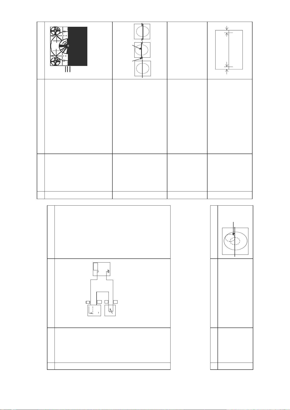
Figure 1.1
A
OK OK NG
A = Out of spec
B=OK
ABC
(PAL 50 Hz).
ADJUSTMENT CONDITION / PROCEDURE
(1) Receive Monoscope Pattern Signal
(2) Choose the service data 02 V-SLOPE.
(3) Adjust the V-SLOPE as shown in Figure 1.1
CAUTION:- PLEASE AGING TV MORE THAN
C = Out of spec
10 MINUTES BEFORE ADJUSTMENT.
Figure:
(PAL 50 Hz).
become 10 ± 1.5 %.
Caution 1: Pls aging TV more than
(PAL 50 Hz).
acceptable vertical position, the monoscope
pattern should be Balance in vertical position.
(1) Receive Monoscope Pattern Signal
(2) Choose the service data 03 V-SHI-50
(3) Adjust V-SHI-50 bus data to have a most
Note: B line (Monoscope middle line) must
same or nearest higher position to the A
mark (Tube middle mark),refer to the attach
drawing.
(1) Receive Monoscope Pattern Signal
(2) Choose the service data 04 V-AMP-50.
10 minutes before adjustment
(3) Adjust V -AMP-50 bus data until the overscan
AB
(PAL 50 Hz).
balance position to spec of A=B
(1) Receive Monoscope Pattern Signal
(2) Choose the service data 05 H-SHI-50 .
(3) Adjust the H-SHI-50 bus data to have a
(as attach drawing).
best point so that B slightly smaller than A.
(4) If cannot make it to A=B , adjust from the
V-SLOPE
(I2C BUS CONTROL)
1
NO ADJUSTMENT POINT WAVEFORM OR OTHERS
V-SHIFT50
(I2C BUS CONTROL)
2
V-AMP-50
(to be done
V-shift adj)
(12C BUS CONTROL)
3
H-SHIFT-50
(I2C BUS CONTROL)
4
3. HORIZONTAL, VERTICAL, DEFLECTION LOOP ADJUSTMENT
Focusing
Point
(middle of
center and
edge of
monoscope
pattern)
signal strength :
signal
56 ± 1 dBµV (75 ohm open).
press R/C to operate auto key
(Hex C1). Blue display with OK
sign indicates the adjustment is
working properly
sign, increase data some step
and please repeat step 2.
* for Auto ADJ
(1) Receive "PAL COLOR BAR"
Signal Strength: 56 ± 1dBµV (75 ohm open)
(1) Receive "PAL COLOR BAR" signal.
(2) Connect the oscilloscope to JA402 (Tuner's
(1) Go to service mode.
(2) Go to service data 01 RF-AGC,
TP201
TV SET
+
0.1V
(3) If appear red display with NG
-
1.0V
-
+
AGC Terminal) as shown in figure 3-1.
OSCILLOSCOPE
mode.
(4) Proceed ste p4&5inmanual
8-1 8-2
BIAS BOX
Adjust the "01RF AGC" bus data to obtain
the Tuner output pin drop 0.1~1.0V below
maximum voltage.
63 ~ 67dBµV , and make sure there is
no noise.
(3) Call "01 RF-AGC" mode in service mode.
(4) Change the antenna input signal to
(5) T urn up the input signal to 90 ~ 95 dBµV to
be sure that there is no cross modulation beat.
ADJUSTMENT CONDITION / PROCEDURE
focusing.
(2) Press R/C to set Picture NORMAL condition.
(3) Adjust the focus control to get the best
FOCUS (1) Receive the "Monoscope Pattern" signal.
RF-AGC TAKE OVER
POINT ADJUSTMEN T
(I2C BUS CONTROL)
(AUT O & MANUAL ADJ )
1
ADJUSTMENT PRECAUTION: Makesure TV Set is in “Normal Condition” before switch to Service Mode for Adjustment.
1. PIF ADJUSTMENT CHECKING
NO ADJUSTMENT POINT ADJUSTMENT CONDITION / PROCEDURE WAV EFORM OR OTHERS
2. FOCUS ADJUSTMENT
1
NO ADJUSTMENT POINT WAV EFORM OR OTHERS
8
Page 9

key.
up
31VSD
the vertical line
If
Dark
White
50% IRE5.5% IRE 9.5% IRE
Display),
Screen
(Dark
Note 1:
During service mode select
does not appear, Please press vol
WINDOW PATTERN SIGNAL
White
Generator SX-1006 (IW ATSU)
or equivalent.
Window Pattern Signal output
level are as above:
*Note : Signal using W/B Pattern
°
DATA before adjust CR T cutoff
(In Window Pattern Signal)
(a) 15 DRI-RS = 32
(b) 16 DRI-GS = 32
(c) 17 DRI-BS = 32
(d) 18 CUT -RS = 16
(e) 19 CUT -GS = 16
(f) 20 CUT -BS = 16
(f) 21 SUB BRI = 24
(g) 22 SUB CON = 59
(h) 32 CUT OFF = 25
(i) 35 BLOC= 4
no signal and press R/C to set picture into
normal condition.
(dark screen display)
low bright, then judge that whether the cut-off
line appear in Red or Green or Blue color, in
this condition between CUT -RS & C UT -GS &
cut-BS, fix the data of the color appear in
cut-off line and adj the other two cut-off data
(Note 1) so that cut-off line color become white.
ADJUSTMENT CONDITION / PROCEDURE
(1) Make sure the following items are in INITIAL
(2) Switch TV to video mode, blue back off, with
(3) Go to service mode, select item 31 VSD
(4) Adjust the Screen so that cut-off line appear in
just disappear
(5) Turn the screen VR of FBT s o that cut-off line
First use Minolta Color Analyzer CA100, let the
gun point at Dark White position (as drawing
become 4 cd/m2 , then let the gun point at
attach), Adj SUB-BRI until LUMINANCE Y
White position (as drawing attach), Adj SUB-
CON until LUMINANCE Y become: 150 cd/m2.
(1) WHITE (HIGH BEAM)
12300 K X : 0.272 , Y : 0.275
Adj the DRI-RS & DRI-BS until the axis of color
temperature become
Let the gun point at Dark White position, if
the color temperature data shift away from
the data adjusted in Item 1 Screen
adjustment, adjust CUT -RS, CUT GS
& C UT -BS.
Please fix the first colour appears in Screen
adj item step (4) is fixed, adj the other two
so that to obtain the similar axis as above.
**Repeatstep1&2togetaregulated
position
(2) DARK WHITE (LOW BEAM)
SCREEN
ADJUSTMENT
(I2C BUS CONTROL)
1
NO ADJUSTMENT POINT WAVEFORM OR OTHERS
screen adj)
(to be done after
(I2C BUS CONTROL)
WHITE BALANCE ADJ
2
4. SCREEN, WHITE BALANCE, SUB-BRIGHTNESS & SUB-CONTRAST ADJUSTMENT
D2
D1
H-BOW
Figure 9.1
H-P AR
Figure 10.1
9-1 9-2
(PAL 50 Hz).
becomes 10 ± 1.5 %.
(PAL 50 Hz).
end of the crosshatch pattern so that the
ADJUSTMENT CONDITION / PROCEDURE
(1) Receive Monoscope Pattern Signal
(2) Choose the service data 06 EW -W -50.
(3) Adjust EW -W -50 bus data until the overscan
(1) Receive CrossHatch Pattern Signal
EW -W-50
(I2C BUS CONTROL)
5
NO ADJUSTMENT POINT WAV EFORM OR OTHERS
E/W -P AR-50
(I2C BUS CONTROL)
6
middle 4 blocks are straight.
(2) Choose the service data 07 E/W -PAR-50.
(3) Adjust the 2nd vertical line from the right
(PAL 50 Hz).
right end of the crosshatch pattern so that the
(1) Receive CrossHatch Pattern Signal
(2) Choose the service data 10 UPCOR-P AR.
(3) Adjust the 2nd upper vertical line from the
UPCOR-P AR
(I2C BUS CONTROL)
7
upper line are straight.
(PAL 50 Hz).
end of the crosshatch pattern so that the
(1) Receive CrossHatch Pattern Signal
(2) Choose the service data 11 LOCOR-P A R.
(3) Adjust the 2nd lower vertical line from the right
LOCOR-P AR
(I2C BUS CONTROL)
8
bottom line are straight.
(PAL 50 Hz).
(1) Receive CrossHatch Pattern Signal
(2) Choose the service data 9 H-BOW .
(3) Adjust the 2nd vertical line from the end of the
H-BOW
(I2C BUS CONTROL)
9
crosshatch pattern until line is straight
(PAL 50 Hz).
(4) Please refer Figure 9.1
(1) Receive CrossHatch Pattern Signal
(2) Choose the service data 8 H -PAR.
(3) Adjust the 2nd vertical line from the end of the
(4) Please refer Figure 10.1
H-P AR
(I2C BUS CONTROL)
10
crosshatch pattern line is straight
(PAL 50 Hz).
end of the crosshatch pattern so that the
D1 (center area of the second vertical
line - edge of screen) and D2 (top area of
the second vertical line - edge of screen)
(1) Receive CrossHatch Pattern Signal
(2) Choose the service data 12 EW -TRAP .
(3) Adjust the 2nd vertical line from the right
are same.
EW -TRAP
(I2C BUS CONTROL)
11
9
Page 10

S ervice L uminanc e
mode (cd/m2) Upper limit Lower limit
E nable 4. 0 +0. 5 -0. 5
Disa ble 4.0 +2.5 -1.0
Toleranc e (c d/m2)
S ervice Lum inanc e
mode (cd/m2) Upper limit Lower limit
E nable 150. 0 +10 -10
Dis able 150. 0 +20 -10
Toleranc e (c d/m2)
R
MgYB
Fig 1-1
Cy G
100% WHITE
controller.
RED-OUT .
ADJUSTMENT CONDITION / PROCEDURE
1. Receive the "PAL Split Color Bar" signal.
2. Make the image normal with the remote
SUB COLOUR
(I2C BUS CONTROL)
1
NO ADJUSTMENT POINT WAVEFORM OR OTHERS
5. PAL CHROMA ADJUSTMENT
Range : 500mV/Div (AC)
3. Connect the oscilloscope to TP47R (R863)
W
(Use Probe 10:1)
Sweep time : 10µsec/Div
remote controller, and vary the sub color data
to make 100% W of the color bar and RED
at the same level for adjustment shown in
4. Set the sub color adjustment mode with the
Fig. 1-1.
6. NTSC CHROMA ADJUSTMENT
ADJUSTMENT CONDITION / PROCEDURE
(1) Receive the "NTSC 3.58 Colour Bar" signal
SUB-TINT
1
NO ADJUSTMENT POINT WAVEFORM OR OTHERS
Same Level
through AV IN from IWATSU SX1006 pattern
generator.
BLUE-OUT
Range : 500mV/Div (AC)
(2) Connect the oscilloscope to TP47B (R865)
sub colour adj)
(to be done after
(I2C BUS CONTROL)
Fig 1-2
WY G R BCy Mg
(Use Probe 10:1)
Sweep time : 10µsec/Div
ADJUSTMENT MODE.. Adjust the "SUB -
TINT" data to obtain the waveform shown
as Figure 1.2 (W and Mg same level)
(3) Select the "SUB-TINT" item in the
Dark White
White
WINDOW PATTERN SIGNAL
WINDOW PATTERN SIGNAL
10-1 10-2
let the gun point at Dark White position
data until :
ADJUSTMENT C ONDITION / PROCEDURE
NO ADJUSTMENT POINT WAVEFORM OR OTHERS
(as attach drawing), adjust SUB-BRI Bus
(1) In Window Pattern Signal condition.
(2) Using Minolta Color Analyzer CA-100,
balance adj)
screen, white
(to be done after
SUB-BRIGHTNESS
(I2C BUS CONTROL)
3
the gun point at White position (as attach
drawing), adjust SUB-CON Bus data until :
(1) In Window Pattern Signal condition.
(2) Using Minolta Color Analyzer CA-100, let
balance adj,
screen, white
SUB-CONTRAST
(to be done after
sub-brightness adj)
(I2C BUS CONTROL)
4
(+)& TP 602(-) (Full Scale: 3mA Range).
(1) Receive the "Monoscope Pattern" signal.
(2) Press R/C to set Picture NORMAL condition.
(3) Connect the DC miliammeter between T P 603
(4) Beam current must be within : 1000 ± 100µA
BEAM
CHECK
CURRENT
5
10
Page 11

*Note:
Please make sure SURROUND is set
to OFF .
If SURROUND I/II ON, Balance
*Note:
1)If SURROUND I/II ON, Balance
function cannot be adjust.
3) SURROUND I: During stereo signal
reception produces a spacious
sound, making the most of the
speaker's performance.
2) SURROUND II :
During monaural signal reception
creates monaural sound that is similar
to stereophonic sound.
function cannot be adjust
11-2
ADJUSTMENT CONDITION / P ROCEDURE
set to select CONTRAST .
CONTRAST effect is OK or not.
set to select COLOUR.
COLOUR effect is OK or not.
set to select B RIGHTNESS.
BRIGHTNESS effect is OK or not.
select TIN T.
GREEN direction and DOWN for R ED direction
whether is O K or not.
set to select S HARPNESS.
SHARPNESSeffectisOKorNOT.
number in green colour under AF T ON condition.
SURROUND.
(1) Receive "Monoscope Pattern" signal.
SURROUND I, II and OFF e ffect.
(2) Press to Menu mode, then select Picture Mode and
(3) Press Volume Up/Down key to check whether the
(1) Receive "Colour Bar" signal.
(2) Press to Menu mode, then select Picture Mode and
(3) Press V olume Up/Down key to check whether the
(1) Receive "Monoscope Pattern" signal.
(2) Press to Menu mode, then select Picture Mode and
(3) Press V olume Up/Down key to check whether the
(1) Receive the "NTSC Colour Bar" signal thru AV in.
(2) Press to Menu mode, then select Picture Mode and
(3) Press V olume Up/Down key to check TIN T, UP for
(1) Receive "Monoscope Pattern" signal.
(2) Press to Menu mode, then select Picture Mode and
(3) Press V olume Up/Down key to check whether the
(1) All C h (1~99) will have an OSD display of the channel
(1) Receive "music" sound signal.
(2) Set MENU, then go into SOUND MENU to select
(3) Press V OLUME UP/DOWN key to check
TREBLE.
effect is OK or not.
BASS.
effect is OK or not.
BALANCE.
the left to right BALANCE e ffect is OK or not.
LOUDNESS.
(1) Receive "music" sound signal.
(2) Set MENU, then go into SOUND MENU to select
(3) Press V OLUME UP/DOWN key to check TREBLE
(1) Receive "music" sound signal.
(2) Set MENU, then go into SOUND MENU to select
(3) Press V OLUME UP/DOWN key to check B ASS
(1) Receive mono-tone signal.
(2) Set MENU, then go into SOUND MENU to select
(3) Press VOLUME U P/DOWN key to check whether
(1) Receive "music" sound signal.
effect is OK or not.
(2) Adjust volume to 10.
(3) Set MENU, then go into S OUND MENU to select
(4) Press VOLUME UP/DOWN key to check LOUDNESS
CONTRAST Key
1
NO ADJUSTMENT POINT WAVEFORM OR OTHERS
COLOUR Key
2
BRIGHTNESS Key
3
TINT Key
SHARPNESS Key
4
5
COLOUR
SURROUND
CH DISPLAY
6
7
TREBLE
8
BASS
9
BALANCE
10
LOUDNESS
11
9. FUNCTION OPERATION CHECKING (VIDEO & AUDIO)
Caution:
AV1 share with YU V. Therefore,
if YUV signal is connected to
Component In terminal, only
component is will detected.
11-1
11-2
four times in "ON" and "OFF"condition before
(C602 positive).
ADJUSTMENT C ONDITION / PROCEDURE
(1) Receive "Monoscope Pattern" signal.
(2) Connect output of Bias Box to D602 cathode
the protector ON and switch to standby mode.
the protector is not working.
(3) Set voltage of Bias Box to 18V and make sure
(4) Set voltage of Bias Box to 28.5V . The tv will
short testing in + B line, check all possible
damaged components on +B line.
(Use random selected set for inspection)
(1) Once finish rectified Electrolytic Capacitor
White Color Bar , Sound 400 Hz 100% Mod).
ADJUSTMENT CONDITION / PROCEDURE
impedance.
(1) Receive the "PAL Color Bar" signal (100%
(2) Terminate the V ideo output with a 75 ohm
Make sure the O/P is as specified
Make sure the output is as specified
(1.0 Vp- p ± 3 dB).
impedance.
(1.76 Vp- p ± 3 dB).
(3) Terminate the Audio output with a 10K oh m
controller, make sure that the modes change
(1) Using the TV/VIDEO key on the remote
a) When connect AV 1 input, check TV als o
in order of T V, AV1,A V2 & T V again and the
b) When connect AV 2 input, check TV als o
video & audio output are according to the
input terminal for each mode.
(2) V ideo cross-talk AV to TV checking :
In terminal and Audio terminal.
controller, press it until the modes change to
COMPONENT , confirm output is appear .
(1) Connect YUV & Audio signal to Component
(2) Using the TV/VIDEO key on the remote
(3) Audio source is share with AV1
H, V PROTECT O R
1
NO ADJUSTMENT POINT WAVEFORM OR OTHERS
7. PROTECTOR OPERATION CHECKING
OTHER PROTECT OR
2
8. A/V INPUT & OUTPUT CHECKING
OUTPUT CHECK
VIDEO AND AUDIO
1
NO ADJUSTMENT POINT W AVEFORM OR OTHERS
INPUT CHECK
VIDEO AND AUDIO
2
CHECK
COMPONENT IN
3
11
Page 12

e
*Note:
For model with M.P.in featur
OOO
3
MODEL QUANTITY ENGLISH CHINESE MALAY
to select B/G, I. Check the sound output is not working properly.
Select D/K and check the sound output to make sure it is working properly.
to select B/G, D/K. Check the sound output is not working properly.
Select I and check the sound output to make sure it is working properly.
to select I, D/K. Check the sound output is not working properly.
key to select modes except SECAM, check the COLOUR is not working properly.
properly.
modes except NTSC 4.43, check the COLOUR is not working properly.
properly.
SYSTEM key to select modes except N4.43/3.58, check the COLOUR is not
working properly. Then, select the "NTSC 4.43/3.58" mode. Check again its
Then, select the "SECAM" mode. Check again its colour so that it is working
key to select modes except PAL, check the COLOUR is not working properly..
Then, select the " PAL" mode. Check again its colour so that it is working properly..
(2) Receive "SECAM COLOUR BAR" signal, press COLOUR SYSTEM
Then, select the "NTSC 4.43" mode. Check again its colour so that it is working
(3) Receive "NTSC 4.43" signal, press COLOUR SYSTEM key to select
colour so that it is working properly..
(4) Receive "NTSC 4.43/3.58 COLOUR BAR" signal thru AV, press COLOUR
(2) Receive "PAL-I" signal, press the "SOUND SYSTEM"
Select B/G and check the sound output to make sure it is working properly.
speakers.
'M.P.IN' OSD will appear at bottom right corner TV screen, RF channel sound will
(3) Receive "PAL-B/G" signal, press the "SOUND SYSTEM"
be switched to M.P.In sound.
(2) Make sure M.P. IN feature is set to ON.
(3) Plug in stereo cable in M.P.In terminal.
(4)
(5) Check the sound is normal.
heard from the speakers. Then put the unit in no signal state.
(3) Check the sound mute is effective..
(4) Finally turn sound level of CTV to minimum.
21S-FX10M
K
CHECKING
14 COLOUR SYSTEM (1) Receive the " PAL COLOUR BAR" signal, press the COLOUR SYSTEM
NO ADJUSTMENT POINT ADJUSTMENT CONDITION / PROCEDURE WAVEFORM OR REMARKS
Note 1:
In NORMAL Mode, when press NORMAL
key, will appear NORMAL OSD and all
setting will set to normal of the AV mode
selected.
15 SOUND SYSTEM (1) Receive "PAL-D/K" signal, press the "SOUND SYSTEM"
16 M.P.IN (1) Turn up the volume control to maximum, make sure the sound is heard from
CHECKING (2) Turn up the volume control to maximum, make sure the sound is
17 NOISE MUTE (1) Receive mono-tone signal.
QUANTITY CHEC
18 OSD LANGUAGE (1) Check OSD LANGUAGE quantity and type for respective model.
12-1 12-2
NORMAL SETTING, WARM for more
more BLUISH direction changing.
TEMP Option, ST ANDARD:
pressed, all the settings will be present to
normal setting. (Normal setting of selected AV
ADJUSTMENT C ONDITION / PROCEDURE
mode)
(1) Once in Picture Mode,and the NORMAL key is
MOVIE MODE MUSIC MODE
CONTRAST 60 CONTRAST 60
COLOUR +6 COLOUR 0
BRIGHTNESS 0 BRIGHTNESS 0
TINT 0 TINT 0
SHARPNESS +6 SHARPNESS 0
WHITE TEM P Mid WHITE TEM P Mid
NEWS MODE
CONTRAST 50
COLOUR -6
BRIGHTNESS 0
TINT 0
SHARPNESS -6
pressed, all the settings will be present to
normal setting (Normal setting of the selected
WHITE TEM P Mid
AV mode)
(2) Once in Audio Menu,and the NORMA L key is
MOVIE MODE MUSIC MODE
SURROUND ONII SURROUND OFF
TREBLE +2 TREBLE +3
BASS +2 BASS +5
BALANCE 0 BALANCE 0
AVL ON AVL O N
LOUDNESS ON LOUDNESS ON
NEWS MODE
SURROUND OFF
TREBLE 0
BASS 0
BALANCE 0
AV L ON
LOUDNESS ON
(1) Receive "Monoscope Pattern" signal.
(2) Set FUNCTION to select WHITE TEM P.
REDDISH direction changing, COOL for
(3) Press Volume Up/Down key to check WHITE
NORMAL K EY
12
NO ADJUSTMENT POINT WAVEFORM OR OTHERS
WHITE TEMP
13
12
Page 13

.
y
13-1 13-2
ADJUSTMENT CONDITION / PROCEDURE WAVEFORM OR OTHERS
(2) Check TV set not damage and TV operation operate correctl
T
1 SHOCK TEST (1) Hit at the top of TV set for two time.
NO ADJUSTMENT POIN
10. SHOCK TEST CHECKING
13
Page 14

NO PICTURE, NO SOUND
Check pin (40) at
IC1001 and related
Check IC1001 and
related circuit.
No snow noise.
circuit.
C heck IC 501.C heck C 511 a nd C 516.
Does noise or signal appear at pin (34)
of IC1001 ?
Does noise or
signal appear at
pin (45) and (46)
of IC1001 ?
Check pin (1) of
SF201, Tuner and
related circuit.
C heck IC 501 bias .
Does the noise level increase at max.
Contrast, Brightness and Sound controls ?
Check pin (40) of
IC1001, Tuner and
related circuit.
Check the tuner AGC at
JA402.
Noise increases but no signal is
received.
Check the tuner supply voltage LB must
approx. 5V. BT must be approx. 33V.
And check the CH preset data.
NO V E R TIC AL S C AN
Tuner.
PIF.
Automatic Gain Control.
CIRCUITS TO BE CHECKED:
(5V), (32V) Power Source.
Check Q601,
Blown out.
Replace the fuse.
Check IC701, D701 and
The fuse is blown out again.
Normal
C705.
Check D760 for 8V regulator
circuit, IC751 for 3.3V regulator
circuit and IC752, D724, D725
for 5V regulator circuit.
Checking the
protector circuit.
Check
IC1001.
Q602 and Q803
Normal
14-1 14-2
Check F701.
Does horizontal circuit
NO RASTER
Check T701 pin (8) voltage
(Approx. 310V at 220V AC)
Check Secondary Main+B
(Approx. 125V)
Check CRT connector K-
wire and the signal on it.
Check 185V
Bias on
CRT board.
oscillate ?
Check IC1001 pin 20.
Check NR701.
Check D751,
IC702 and IC703
14
Page 15

Is the white ba lance properly
adjus ted ?
Is s ome colour produced in
B /W broa dcas t reception ?
R e-a djust the white balance .
The picture colour is yellow.The picture colour is ma genta.The picture colour is c yan.
C heck IC 851 pin (7) and its
adja cent circuits .
C heck IC 1001 a nd bias
NO C OLO UR
C heck IC 851 pin (8) and its
adja cent circuits .
“ P AL / S E C AM / NT S C ”
control c ircuit.
C heck X801 (24. 576 MHz)
NO S P E C IFIC C OL OUR
(NO COL OUR S YNC HR ONIZAT ION)
C heck IC 1001.
C heck IC 851 pin (9) and its
adja cent circuits .
C heck TV s ound from pin ( 25) &
pin (26) of I C 1001.
YES (S ignal)
C heck IC 301 and
NO S OUND
Doe s s ignal a ppea r at pins
(11) a nd (12) of I C 3801 ?
Doe s s ignal a ppea r at pins
(2) a nd (4) of IC 301 ?
C ontrol.
S ound Detector C ircuit.
S ound S witch and Att.
C IR CU ITS T O B E C HE C KE D:
Audio O utput C ircuit.
peripheral c ircuit.
C heck pins (20), (21), ( 47)
and (48) of I C 1001.
R e-a djust vertical s ize.
(B us Da ta )
Vertical linea rity and s ize a re
NE ITHE R V E R T IC AL NOR
C heck S peaker.
HOR IZONT AL S Y NC HR ONIZA T ION
S ync. S epa rator C ircuit.
C IR CU IT T O B E C HE CK ED:
AND V E R TIC AL L INE AR IT Y
DE F E CT IV E VE R TIC AL A MP .
abnorma l.
C heck R 503, R 506 a nd
R 521.
15-1 15-2
15
Page 16

WAV E F OR MS
(1) 1.9 Vp-p (H)
(5) 4.43 Vp-p (H)
(9) 42.1 Vp-p (H)
(2) 2.34 Vp-p (H)
(6) 5.99 Vp-p (H)
(10) 1.102 KVp-p (H)
(3) 2.09 Vp-p (H)
(6) 0.944 Vp-p (V)
(11) 64.9 Vp-p (V)
(4) 2.44 Vp-p (H)
(8) 3.97 Vp-p (H)
(12) 1.94 Vp-p (V)
(13) 156.5 Vp-p (H)
(17) 2.32 Vp-p (H)
(21) 126 Vp-p (H)
(14) 525 Vp-p
(18) 2.63 Vp-p (H)
(15) 5.99 Vp-p (V)
(19) 131.5 Vp-p (H)
(16) 2.52 Vp-p (H)
(20) 112.5 Vp-p (H)
16
Page 17

S O L ID S TAT E DE V IC E B A S E DIA G R A M
17
Page 18

18
Page 19

B L OC K DIA G R A M
C R T U NIT
S HA K IT U N IT
19
Page 20

B L O C K DIA G R A M
MA IN UNIT
2120
Page 21

DESCRIPTION OF SCHEMATIC DIAGRAM
SAFETY NOTES:
1. DISCONNECT THE AC PLUG FROM THE AC OUTLET BEFORE
REPLACING PARTS.
2. SEMICONDUCTOR HEAT SINKS SHOULD BE REGARDED AS
POTENTIAL SHOCK HAZARDS WHEN THE CHASSIS IS OPERATING.
IMPORTANT SAFETY NOTICE:
PARTS MARKED WITH " " ( ) ARE IMPORTANT FOR
MAINTAINING THE SAFETY OF THE SET. BE SURE TO REPLACE THESE PARTS WITH SPECIFIED ONES FOR MAINTAINING THE SAFETY AND PERFORMANCE OF THE SET.
SERVICE PRECAUTION:
THE AREA ENCLOSED BY THIS LINE (
CONNECTED WITH AC MAINS VOLTAGE.
WHEN SERVICING THE AREA, CONNECT AN ISOLATING TRANSFORMER BETWEEN TV RECEIVER AND AC LINE TO ELIMINATE
HAZARD OF ELECTRIC SHOCK.
) IS DIRECTLY
NOTES:
1. The unit of resistance "ohm" is omitted.
(K = 1000 ohms, M = Mega ohm).
2. All resistors are 1/16 watt, unless otherwise noted.
3. All capacitors are mF, unless otherwise noted. (P = mmF).
VOLTAGE MEASUREMENT CONDITIONS:
1. Voltages in parenthesis measured with no signal.
2. Voltages without parenthesis measured with 3mV B & W or Colour signal.
3. All the voltages in each point are measured with VTVM.
WAVEFORM MEASUREMENT CONDITIONS:
1. The colour bar generator signal of 1.0V peak applied at pin (24)
of IC201.
2. Approximately 4V AGC bias .
22
Page 22

S C H E MAT IC DIA G R A M: C R T U NIT
J
I
H
G
F
E
D
C
B
A
1 2 3 4 5 6 7 8 9 10
23
Page 23

SCHEMATIC DIAGRAM: MAIN UNIT
J
I
H
G
E
F
D
C
B
A
1 2 3 4 5 6 7 8 9 10
11 12 13 14 15 16 17 18 19
2524
Page 24

S C H E MAT IC DIA G R A M: S HA K IT UNIT
J
I
H
G
F
E
D
C
B
A
1 2 3 4 5 6 7 8 9 10
26
 Loading...