

Page 1

SC
AUTOMATIC PARTS
WASHER
■ SC-2412A ■ SC-2412D
For technical assistance or the SHARK dealer nearest you, call 1-800-771-1881
or visit our website at www.shark-pw .com
97-6267
Page 2

Page 3

SECTION 1
Introduction and Safety
Using This Manual 5
General Safety Inf ormation 5
Component Identification 6-7
SECTION 2
Installation
Before you Begin 8
Step 1: Mak e Electrical Connections 8
Step 2: Connect a Compressed-Air Line and Accessories 8
Step 3: Connect a Water Line 8
Step 4: Fill the Machine with Water and Add Detergent 9
SECTION 3
Operation
CONTENTS
Main Operating Components 10
Control Panel 10
Thermostat 11
24-hour, 7-da y Heater Timer 11
Lid Safety Switch 11
Turntable Assembly 11
Debris Screen 12
Air Flow Valv e (Delux e Edition only) 12
Po wer Brush (Delux e Edition only) 12
Detail Brush and Flow Regulator (Deluxe Edition only) 12
Dual Oil Separator (DOS) System 13
Low W ater Shut-off System 13
Automatic W ater Fill 13
Detergents and Additives 14
Detergent 15
Rust Inhibitor Additive 16
Preparing the Machine for Use 17
3
SHARK SC-2412 • 97-6267 • REV. 3/04
Page 4

CONTENTS
Washing P arts 19
Shutting Down the Machine 19
SECTION 4
Troubleshooting
Overview 20
Troubleshooting the Electrical System 20
T esting Individual Components 20
SECTION 5
Maintenance and Repair
Maintaining the Machine 21
Daily Maintenance 21
Weekly Maintenance 21
Monthly Maintenance 21
Using the DOS System 21
Cleaning and Aligning the Spray Nozzles 22
Cleaning out the Sump 22
Repairing the Machine 23
Heating Element 23
Thermostat 23
Timers and Switches on the Control Panel 23
T orque Limiter 23
T urntable Motor 24
WARRANTY
Model Number ______________________________
Serial Number ______________________________
Date of Purchase ____________________________
The model and serial numbers will be found on a decal attached to
the parts washer. You should record both serial number and date of
purchase and keep in a safe place f or future ref erence .
4
SHARK SC-2412 • 97-6267 • REV. 3/04
Page 5

WARNING
WARNING
WARNING
Section 1: Introduction
AUTOMATIC PARTS WASHER
This manual is intended as a guide for saf ely installing,
operating and maintaining your Automatic P arts Washer .
We reserve the right to make changes at any time without incurring any obligation.
Owner/User Responsibility:
The owner and/or user must hav e an understanding of
the manufacturer’ s operating instructions and warnings
before using this machine. Warning information should
be emphasized and understood. If the operator is not
fluent in English, the manufacturer’s instr uctions and
warnings shall be read to and discussed with the operator in the operator’s native language by the purchaser/owner, making sure that the operator comprehends its contents.
Owner and/or user must study and maintain for future
reference the manufacturers’ instructions.
This manual should be considered a permanent
part of the machine and should remain with it if
machine is resold.
When ordering parts, please specify model and
serial number .
GENERAL SAFETY
INFORMATION
WARNING
READ OPERATOR’S
MANUAL
THOROUGHLY
PRIOR TO USE.
2. Improper installation could cause serious injury to
the machine. All installations must comply with local codes. Contact your electrician, plumber, utility
company or the selling distributor for specific details.
3. The machine can only operate on the type of electrical power indicated on the electrical specifications
tag. Oper ating the machine on any other power supply will permanently damage the motors.
CAUTION: To reduce the risk of
injury, read operating instructions carefully before using.
1. Read the owner's manual thoroughly. Failure to follow instructions could cause a malfunction of the evaporator and
result in death, serious bodily
injury and/or property damage.
WARNING: Electrical shock
could cause serious injury or
death.
4. Install the machine in compliance with the National Electric
Code, connect it to a properly
KEEP WA TER SPRAY
AWAY FROM
ELECTRICAL WIRING.
sized lockable disconnect and
ground the machine using the
grounding stud inside the main
electrical panel.
5. While operating the machine, keep all electrical panels in place and securely fastened at all times.
6. Disconnect the machine completely from the outside power source before servicing.
WARNING: Hot, high pressure
cleaning solution could cause
serious injury .
7. Do not operate the machine
with the lid or door open and
do not override the safety
HIGH PRESSURE
SPRAY CAN PIERCE
SKIN AND TISSUES.
switch.
8. After the machine stops, wait
10 seconds before opening the
lid or door.
WARNING: Always wear approved eye protection and protective clothing while operating
machine.
9. Always wear rubber gloves
PROTECTIVE
EYEWEAR AND
CLOTHING MUST
BE WORN.
when loading and unloading
the machine or servicing components in the processing
chambers or sumps.
WARNING: Slips and falls could cause serious injury.
10. Maintain an unobstructed work area around the machine and keep the floor free of water , oil, grease or
other foreign substances.
This Automatic Parts Washer is designed to operate
safely and efficiently with a minimum of required maintenance. Before you begin to install and use the machine, please familiarize yourself with the major components.
OPERATOR’S MANUAL
5
SHARK SC-2412 • 97-6267 • REV. 3/04
Page 6
AUTOMATIC PARTS WASHER
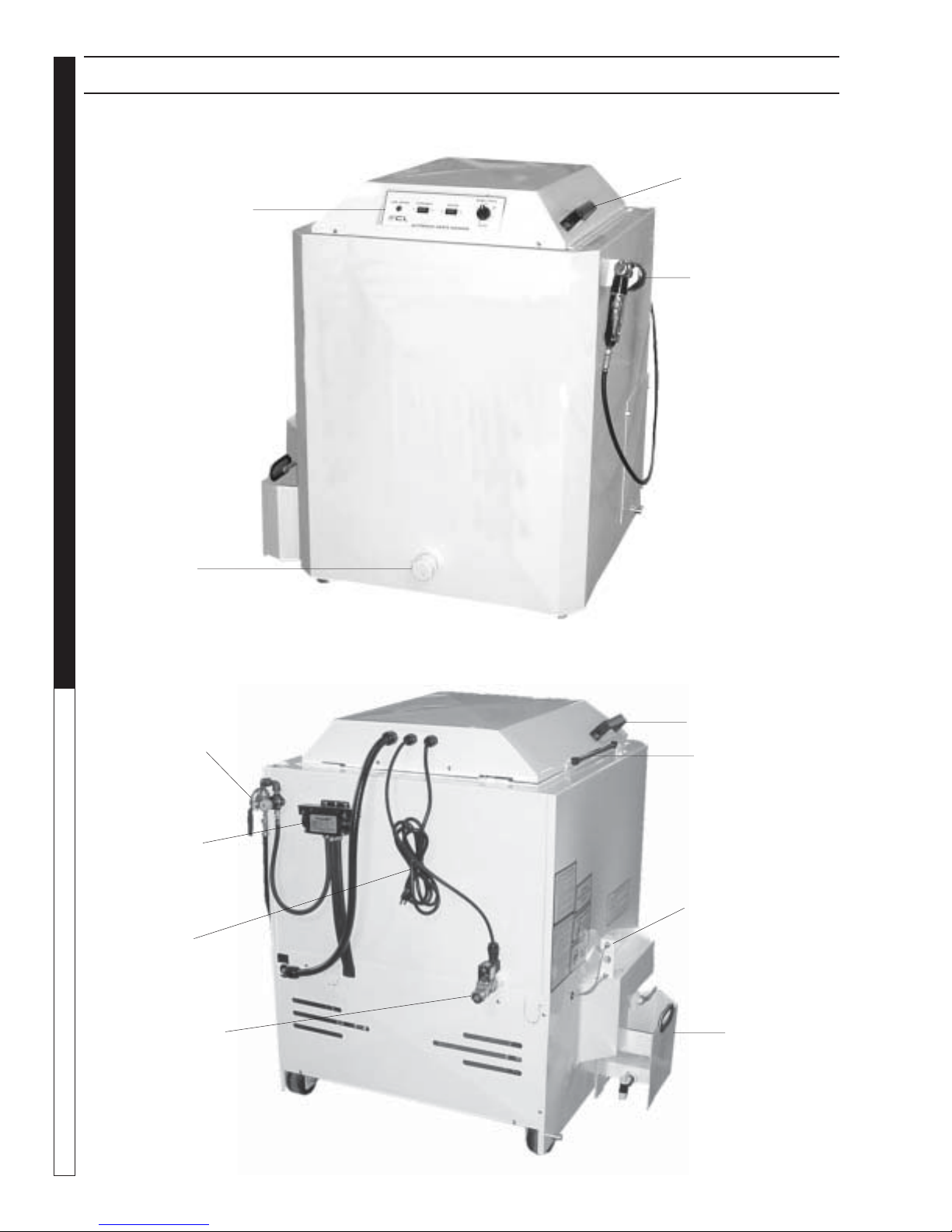
COMPONENT IDENTIFICATION
FRONT
Lid Handle
Control Panel
Optional Power
Brush
OPERATOR’S MANUAL
Sump Drain
Optional Air Flow
Valve w/Flow
Regulator
Optional Detail
Brush Pump
Power Cord
REAR
Lid Handle
Lid Support Strut
Low Water Shut-Off
System
Optional Automatic
Water Fill Assembly
6
DOS System™ w/
Optional Oil
Collection Container
SHARK SC-2412 • 97-6267 • REV. 3/04
Page 7
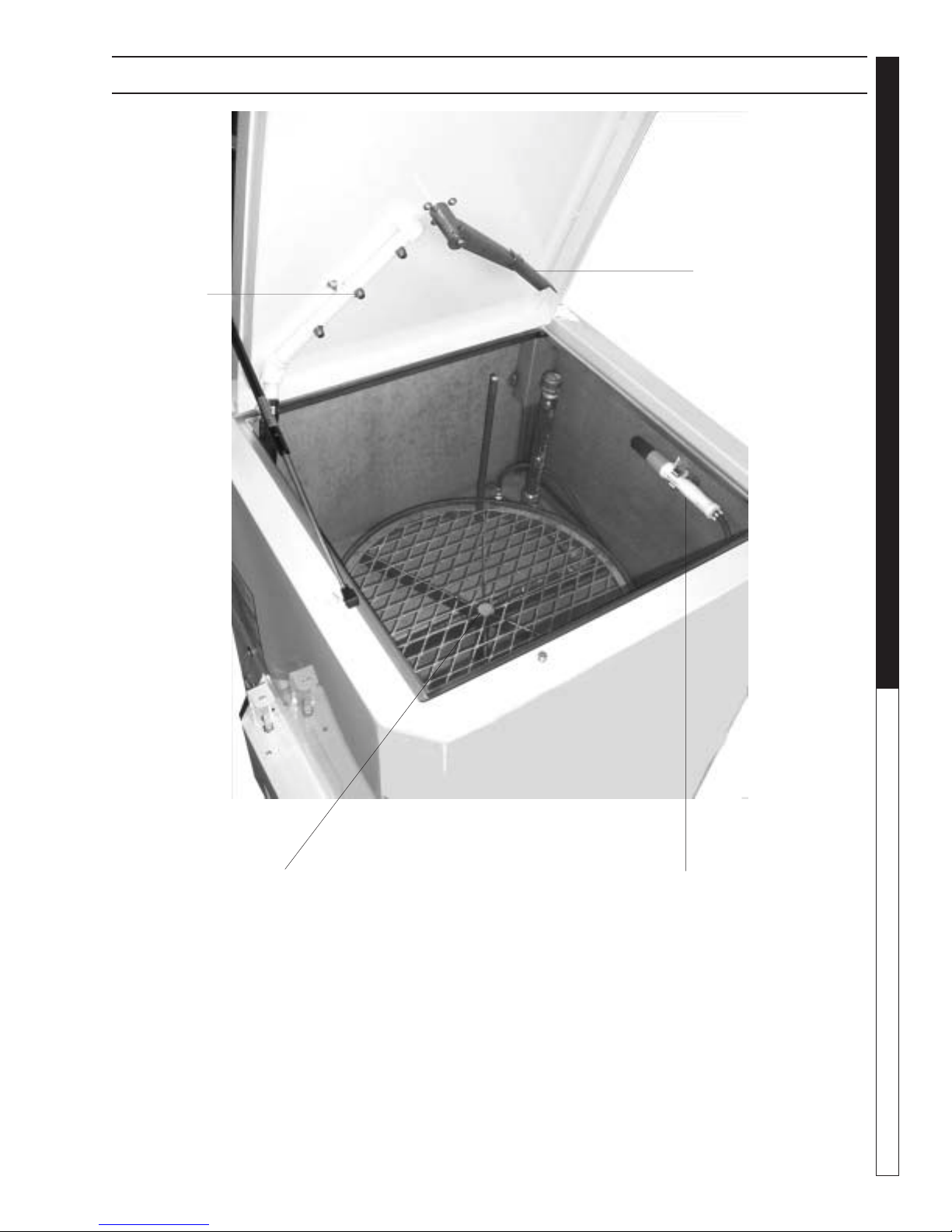
COMPONENT IDENTIFICATION
AUTOMATIC PARTS WASHER
Spray Pipes
and Nozzles
Turntable Drive Arm
OPERATOR’S MANUAL
Turntable Assembly w/
Optional Removable
Containment Ring
Optional Detail
Brush
7
SHARK SC-2412 • 97-6267 • REV. 3/04
Page 8
Section 2: Installation
BEFORE YOU BEGIN
To prepare to install the machine, choose an unobstructed, level site that allows convenient access for
operators and maintenance personnel. Sources for
water and electrical power should be located near the
installation site. If your machine is equipped with the
optional power brush and hand detail brush you must
also run a compressed air line to the installation site.
If you have any questions regarding the installation,
please contact your distributor or call a customer service representative. When contacting customer service
please refer to the machine identification tag inside the
AUTOMATIC PARTS WASHER
front cover of this manual for detailed machine specifications.
STEP 1: MAKE ELECTRICAL
CONNECTIONS
These machines are shipped with a factory-installed
power cord. To connect the machine to a power supply ,
plug the cord into a grounded outlet on a single-outlet
circuit. It is important that you connect the machine to
OPERATOR’S MANUAL
a single-outlet circuit to avoid possib le damage resulting from inadequate supply amperage.
STEP 2: CONNECT A
COMPRESSED-AIR LINE AND
ACCESSORIES
This step is required for machines equipped with the
optional power brush and hand detail brush.
If your machine does not have these options, skip the
following procedure.
Note: To ensure proper operation and to minimize the
possibility of premature component failure, make sure
the compressed air is supplied at 75 to 90 psi. W e also
recommend an in-line moisture trap and an in-line lubricator on the main air supply line. Refer to the documentation provided with the power brush for more information.
Step 1:
Remove the pow er brush from the bo x, install the wire
brush in the chuck, and connect the air hose.
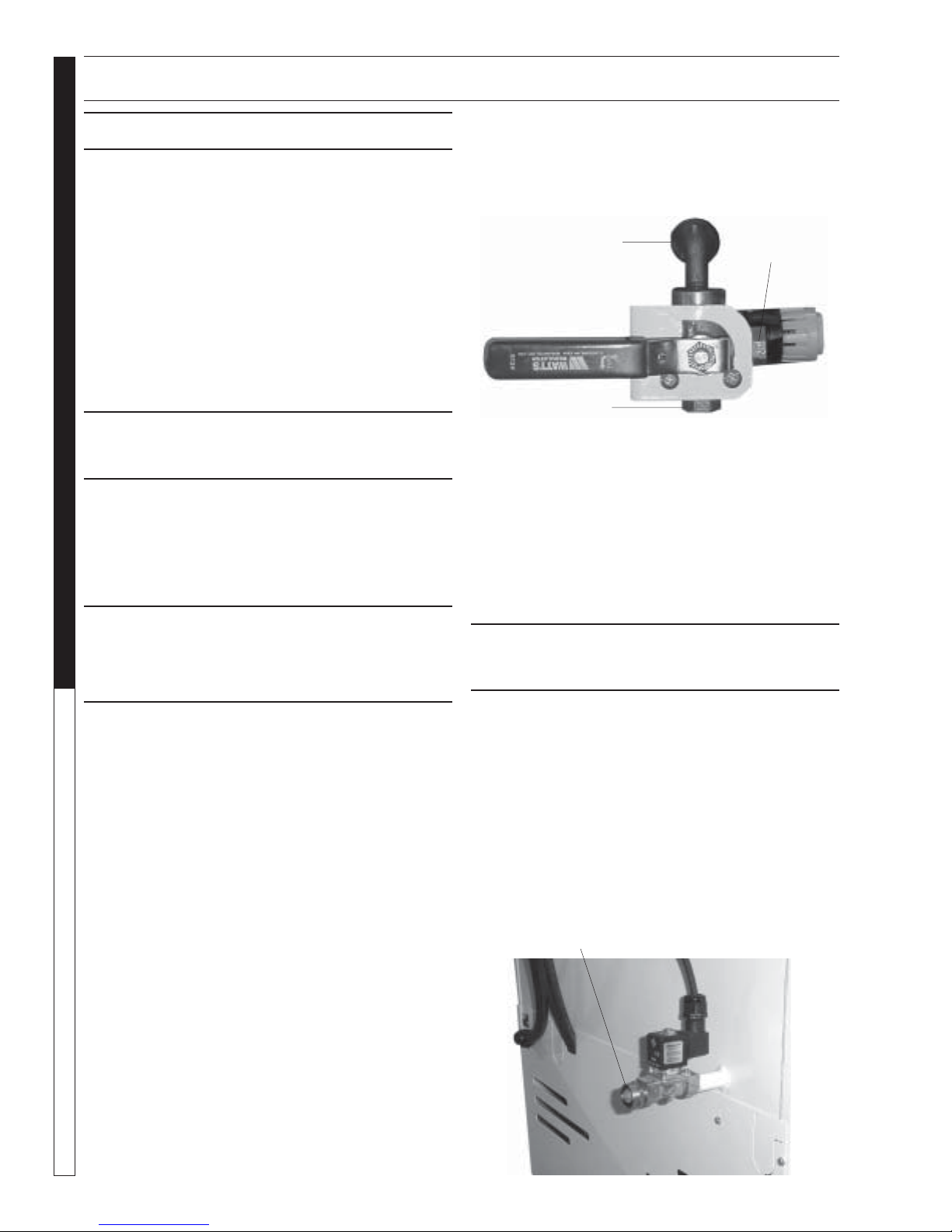
Step 2:
Familiarize yourself with the three-way air flow valve
(See Figure Below), then install a fitting (if necessary)
to accommodate a connection to your compressed-air
supply.
Line to Detail
Brush Pump
Power Brush
Connection
Step 3:
Connect the shop compressed-air line to the machine.
Step 4:
Connect the hose from the power brush to the air flow
valve.
Step 5:
Hang the power brush on the bracket mounted along
the right side of the machine.
Compressed Air
Connection
STEP 3: CONNECT A WATER
LINE
This step is required for machines equipped with the
optional automatic water fill feature. If your machine does
not have this option, skip this step .
The optional automatic water fill feature automatically
maintains the correct water lev el in the sump. The f eature requires that you connect the machine to a dedicated water supply line.
T o connect the machine to a w ater supply line, attach a
suitable burst-proof hose to the hose connection on the
rear of the machine (See Figure Below), then connect
the hose to a nearby water spigot.
Hose Connection
8
SHARK SC-2412 • 97-6267 • REV. 3/04
Page 9

Section 2: Installation
AUTOMATIC PARTS WASHER
Note: The machine is designed for portability, and some
maintenance tasks require that you mov e the machine.
DO NOT make a permanent connection from your shop
water supply to the machine.
STEP 4: FILL THE MACHINE
WITH WATER AND ADD
DETERGENT
Step 1:
Familiarize y ourself with the lo w water shut-off system
on the left side of the machine (See Figures Below).
Target Aligned w/
Lower Switch
Target Aligned w/
Upper Switch
Step 3:
Close the lid.
Step 4:
Flip the heater switch to the ON position.
The sump water will reach operating temperature (160°-
180°F) in approximately f our hours.
To avoid having to wait f or the wash solution to heat up
before you use the machine each day, install an optional 24-hour 7-day heater timer. Refer to 24-hour, 7day Heater Timer” for more information.
IMPORTANT: Allow the sump water to reach operating
temperature before adding detergent and running the
machine. If y ou add detergent and run the machine when
the sump water is cool, the detergent will foam excessively and could ov erflow the machine .
Step 5:
Add appropriate amount of detergent
ber. To ensure that the detergent dissolves properly,
spread it evenly throughout the w ash chamber.
Note: The manufacturers detergents are the only de-
tergents approved for use with this automatic parts
washer. They are specially formulated with rust inhibitors and anti-foaming agents to optimize performance
and minimize maintenance. The use of an y other detergent during the warranty period will void the warranty.
Step 6:
Turn the wash cycle timer and allow the machine to
complete the cycle to dissolve the detergent into the
water . When the machine stops, it is ready f or use . Refer to
Section 3: Operation
structions.
for complete operating in-
to the wash cham-
OPERATOR’S MANUAL
Step 2:
Fill the sump with water .
If your machine is equipped with the optional automatic
water fill feature, simply turn the water on; the automatic
water fill feature will automatically turn off the water when
the sump is full.
If your machine is not equipped with optional automatic
water fill feature, add w ater through the wash chamber
until the low water shut-off system indicates that the
sump is full. The sump capacity is 25 gallons.
SHARK SC-2412 • 97-6267 • REV. 3/04
9
Page 10

Section 3: Operation
MAIN OPERATING
COMPONENTS
Familiarize yourself with the main oper ating components
before operating the machine.
CONTROL PANEL
The control panel is located on the front center of the
lid. It contains the heater, wash cycle, turntable controls, and low water indicator (See Figure Below).
AUTOMATIC PARTS WASHER
OPERATOR’S MANUAL
Low Water
Indicator
Low Water
Indicator
Wash Cycle
Timer w/Knob
Heater Switch
Wash Cycle Control
The wash cycle control is a timer switch. When set, the
timer automatically shuts off the pump and turntable
when the wash cycle is complete.
Thermostat
The thermostat is located inside pump enclosure. The
thermostat is factory-set to heat the wash solution to a
maximum temperature of 180 °F.
Adjusting the Thermostat
To adjust the thermostat, rotate the adjustment screw
or knob clockwise to increase the temperature, or counterclockwise to decrease the temperature (See Figure
Below).
Decrease
Temperature
Increase
Temperature
Low Water Indicator
The low water indicator light illuminates if the wash solution in the sump is low. For more information refer to
Low W ater Shut-off System
.
Turntable Switch
The turntable switch is an illuminated rocker s witch that
enables you to disconnect pow er to the turntable motor.
Set to ON, the turntable rotates during the wash cycle.
Set to OFF, the turntable does not rotate during the wash
cycle. The switch is useful for washing large parts that
would otherwise impede turntable rotation.
Heater Control
The heater control is an illuminated rocker switch. It
controls the heating element in the sump chamber. The
heater control illuminates when the heating system is
on. The heating system is ther mostatically set at the
factory to reach a high temperature of 180 °F. The temperature is adjustable using the thermostat (See
mostat
).
Note: The machines contain an internal power relay that
automatically disconnects power to the heater when the
pump turns on; the heater and pump cannot run simultaneously (120V only). After long w ash cycles it may be
necessary to let the machine sit idle for a period of time
to allow the wash solution to reheat to operating temperature.
Ther-
Adjustment
Screw
24-hour, 7-day Heater Timer
A 24-hour, 7-da y heater timer is a vailable as an option
on these machines. The timer plugs directly into a 15amp outlet and automatically cycles the heating system on and off each day. To configure the timer, ref er to
the instructions printed on the back of the timer housing.
To order a 24-hour, 7-day heater timer, contact your
distributor or call customer service.
Lid Safety Switch
10
SHARK SC-2412 • 97-6267 • REV. 3/04
Page 11

Section 3: Operation
AUTOMATIC PARTS WASHER
The lid safety s witch is located behind the front left lip of
the lid, just below the control panel (See Figure Below).
The safety switch disconnects po wer to the water pump
and the turntable motor if the lid is raised during operation.
Lid Safety Switch
Turntable Assembly
The turntable assembly uses a torque arm mounted on
the underside of the lid to rotate the turntable (See Figure Below). The torque arm includes a torque limiter
which prevents the turntable motor from b urning out in
case a part falls off the turntable and obstructs rotation.
For information on adjusting the torque limiter, refer to
Torque Limiter
table motor , refer to
. For information on replacing the turn-
Turntable Motor
Torque Limiter
.
Removing the Turntable
To remove the turntable, grasp it evenly on opposite
sides and lift it free of the spindle.
Important: The turntable rotates on a thrust bearing
inside of the hub. As you lift the turntable free of the
spindle, take care not to jar the thrust bearing loose. If
the thrust bearing drops out of the hub, inspect it for
wear then either replace it or re-install it (See Previous
Figure).
Debris Screen
The debris screen is located below the turntable inside
of the wash chamber (See Figure Below). The debris
screen continuously filters debris particles from the
cleaning solution to ensure blockage free spra y nozzle
operation, and also provides a safeguard against small
parts that might accidentally be washed through from
the wash chamber .
The frequency at which you must clean the debris
screen depends on machine usage. In general, you
should clean the screen before operating the machine
each day. To access and remove the screen you must
remove the turntable (see
Note: Never operate the machine without the debris
screen in place. The screen is specially sized to filter
particles that could clog the spray nozzles or damage
the water pump. Operating the machine without the
debris screen in place could cause spray nozzle clogging or water pump failure.
Removing the Turntable
).
OPERATOR’S MANUAL
Torque Arm
Turntable
Thrust Bearing
Air Flow Valve (
Deluxe Edition
only)
The air flow valve is located on the right rear corner of
the machine. It is a three-way ball valve that controls
the flow of compressed air to the power brush and the
hand detail brush (See Figure Below).
Detail Brush
Power Brush
Detail Brush
Pump
Air In
Power Brush
11
SHARK SC-2412 • 97-6267 • REV. 3/04
Page 12

Section 3: Operation
Power Brush (
Deluxe Edition only
)
The power brush is located on the right front corner of
the machine (See Figure Below). Refer to
nect a Compressed-Air Line and Accessories
Step 2: Con-
for de-
tailed installation information.
Throttle
Lever
AUTOMATIC PARTS WASHER
Throttle
Note: The power brush is available as an option on this
machine. For ordering information, contact your distributor or call customer service.
Using the Power Brush
Warning: P articles dislodged by the power brush could
OPERATOR’S MANUAL
cause serious injury to your eyes. Always wear appro ved
eye protection when using the pow er brush.
With stiff stainless steel bristles turning at 1800 RPM,
the power brush easily removes carbon deposits, old
gasket material, or other tightly-adhered materials from
parts before washing.
To turn on the power brush, position the air flow select
valve appropriately, then push the power brush lever
lock forward with your thumb and squeeze the throttle
lever to control the speed of the brush.
Detail Brush and Flow Regulator (
Edition only
The detail brush is located on the front inside wall of the
wash chamber . The flow regulator is located on the right
rear corner of the machine (See Following Figure). The
detail brush uses a continuous flow of hot cleaning solution through its nylon bristles to help you clean delicate or lightly soiled parts. The flow regulator controls
the flow of cleaning solution through the detail brush.
Warning: Hot, high-pressured cleaning solution could
cause serious injury. Always wear rubber gloves and
approved eye protection when handling hot cleaning
solution.
Lever Lock
Deluxe
)
Adjusting the Flow of Cleaning Solution
The flow of cleaning solution through the detail brush is
pre-set at the factory . If you need to adjust the flo w , pull
out the flow regulator knob, then rotate it clockwise to
decrease the flow or counter-clockwise to increase the
flow . After adjusting, push the knob back in to lock it.
Flow Regulator,
Behind
Machine
Detail Brush
Note: The detail brush is available as an option on this
machine. For ordering information, contact your distributor or call customer service.
Dual Oil Separator (DOS) System
The DOS System™ is located on the lower left side of
the machine (See Figure Below). It is made up of an oil
decant valve, a removable oil collection container, and
a water decant valve . The DOS System removes oil from
the cleaning solution to prolong its useful life. Refer to
Using the DOS System
tions.
for detailed operating instruc-
Oil Decant Valve
Optional Oil
Collection
Container
12
Water Decant
Valve
SHARK SC-2412 • 97-6267 • REV. 3/04
Page 13

Section 3: Operation
AUTOMATIC PARTS WASHER
Low Water Shut-off System
The low water shut-off system shuts down the machine
if the wash solution in the sump chamber drops below a
safe lev el. The system uses two pro ximity switches and
a float rod mounted on the right outer wall of the sump
chamber to control the water lev el (See Figure Below).
Target Aligned w/
Lower Switch
Target Aligned w/
Upper Switch
If the wash solution drops below the lower proximity
switch, the low water indicator light on the control panel
turns on and the system disconnects power to the heating element, the pump, and the turntable motor. T o reset the system, add water to the sump until the low water
indicator light turns off.
WATER LEVEL OK:
Both switches OPEN, Automatic
Water Fill Valve (if installed) CLOSED,
Heating Element ON.
CLOSED, Automatic Water Fill Valve (if
installed) OPEN, Heating Element OFF.
LOW W ATER LEVEL:
Top switch CLOSED, Bottom Switch
Automatic W ater Fill
The automatic water fill system automatically maintains
a proper water level in the sump. It is available as on
option on these machines.
The automatic water fill system uses the low water shutoff proximity switches to open and close a water solenoid valve, which automatically maintains a proper water level in the sump. The figure below describes the
operation of the automatic water fill system.
DETERGENTS AND
ADDITIVES
Detergent
Factory approved detergents are the only detergents
approved f or use with the manufacturers automatic parts
washers. They are specially formulated with rust inhibitors and anti-foaming agents to optimize performance
and minimize maintenance. The use of an y other detergent during the warranty period will void the warranty.
T o monitor the relativ e concentration of the detergent in
the wash solution, periodically examine the wash solution in the sump chamber for the follo wing indicators:
• Rust inside the machine: not enough detergent
• Excessive foaming: not enough detergent
• Thick, white residue on parts after washing:
too much detergent
Note: To maintain proper detergent concentration under normal operating conditions follow factory directions.
SUMP FILLING:
Top switch CLOSED, Bottom Switch
OPEN, Automatic Water Fill Valve (if
installed) OPEN, Heating Element OFF.
OPERATOR’S MANUAL
13
SHARK SC-2412 • 97-6267 • REV. 3/04
Page 14

Section 3: Operation
Rust Inhibitor Additive
Factory detergents protects the entire inside of your machine against the degenerative effects of w ater e v aporation. It actually evaporates with the water and continuously coats and protects metal surfaces, e ven while
your machine is sitting idle. F or more inf ormation, contact your distributor or call customer service.
PREP ARING THE MACHINE
FOR USE
Before you begin to wash parts, it is important that you
properly prepare the machine. Bef ore y ou begin to use
AUTOMATIC PARTS WASHER
the machine each day:
• check the water level and add water to the sump
tank if necessary;
• heat the water to operating temperature
• add detergent if necessary (see “Detergents and
Additives”);
• verify that none of the spray nozzles are clogged;
and
• clean the debris screen.
OPERATOR’S MANUAL
WASHING PARTS
The following procedure assumes that the heater is on
and the sump water is at operating temperature.
To wash parts, perform the following procedure.
Warning: Hot, high-pressured cleaning solution could
cause serious injury. Always wear rubber gloves and
approved eye protection when loading and unloading
the machine.
Step 1:
Load large, heavy parts directly onto the turntable. Load
small, light parts in the optional small par ts basket, if
available. Make sure none of the parts extend beyond
the edge of the turntable and make sure large, light parts
(valve cov ers, for e xample) are secured to the turntable.
Note: For optimum cleaning performance, provide a
slight clearance between parts to allow adequate flow
of cleaning solution around and between them.
Step 2:
Close the lid.
Note: If you are washing large parts that might impede
turntable rotation, flip the turntable switch OFF.
Step 3:
Set the wash cycle timer.
Step 4:
When the machine stops, lift the lid and wait a fe w moments to allow the parts to cool and dry before removing them. Most parts flash-dry in seconds.
SHUTTING DO WN THE
MA CHINE
To shut down the machine at the end of the day:
• set the wash cycle control to OFF;
• set the heater control to ON to enable automatic
turn-on the following day;
• shut off the compressed air at the supply line (if
installed).
WARNING
• For periods of extended shut-down (w eekends and
holidays, f or example), disconnect power to the machine.
• If your machine is equipped with an optional pro-
grammable heater timer , periodically verify the settings to prevent inadv ertent unattended operation.
14
SHARK SC-2412 • 97-6267 • REV. 3/04
Page 15

Section 4: Troubleshooting
MELBORPESUACELBISSOPNOITULOS
AUTOMATIC PARTS WASHER Troubleshooting Guide
GNINAELCROOP
ECNAMROFREP
rehto
detaeh
ylreporp
NOITULOSHSAW
GNITAEHTON
esufnwolBotrefeR
sihctiwselbatnruT FFO sihctiwselbatnrutehttahtyfireV NO eeS( elbatnruT
hctiwS .)
hcaegnitcurtsboerastraP
.meht
pmusnilevelretawwoL .yrassecenfiretawdda;levelretawpmuskcehC
ylreporpmirodeggolC
selzzonyarpsdengila
noitartnecnoctnegretedwoL gninaelcevresbodnatnegretedfospoocs2-1ddA
ylreporptonsinoituloshsaW
gnitarepotonsipmuP
pmusnilevelretawwoL firetawdda;pmusehtnilevelretawehtkcehC
tesyltcerrocnisitatsomrehTeeS(°081ottes;gnittestatsomrehtkcehC gnitsujdA
eeS
eeS
eeS(yrassecen ffO-tuhSretaWwoL .)
tatsomrehTeht .)
selzzoNyarpSehtgningilA .)
eeS(yrassecenfingiladnanaelc dnagninaelC
gnitaehtonsinoituloshsaw
.
ylreporpetarepotonseodpmup
.
strapnoitisop;elbatnrutnostrapfonoitisopehtkcehC
neewtebdnadnuoranoitulosgninaelcfowolfwollaot
;tnemngiladnasnoitcurtsborofselzzonyarpskcehC
.yrassecenfieromspoocs2-1dda;ecnamrofrep
metsySlacirtcelEehtgnitoohselbuorT
.
putliubsisirbedssecxE
tnemelegnitaehdnuora
wolootsiegatloveniL ehttahtyfirevotnaicirtceledesnecilatcatnoC
remitretaehdeliaF eeS(yrassecenfiecalper;remittaehehttseT hsaW
tatsomrehtdeliaF eeS(yrassecenfiecalper;tatsomrehtehttseT elgniS
tnemelegnitaehdeliaF eeS(yrassecenfiecalper;tnemelegnitaehehttseT
eeS(yrassecenfituonaelc )pmuSehttuogninaelC .
.stnemeriuqersteemegatlovenilgnimocni
)sremiTretaeHdnaelcyC .
,tatsomrehTesahP otecivresremotsuctcatnocro
.)tatsomrehtesahp-eerhtatset
,tnemelEgnitaeHelgniS ecivresremotsuctcatnocro
.)tnemelegnitaehesahp-eerhtatsetot
;tnemelegnitaehdnuorapudliubsirbedrofkcehC
15
SHARK SC-2412 • 97-6267 • REV. 3/04
Page 16

Section 4: Troubleshooting
MELBORPESUACELBISSOPNOITULOS
OTSLIAFENIHCAM
NEHWTRATS
"STRAPGNIHSAW"
SIERUDECORP
DEWOLLOF
ylreporp
SEODELBATNRUT
ETAREPOTON
YLREPORP
sihctiwselbatnruT FFO ehtnisihctiwselbatnrutehttahterusnE no noitisop
gnitcurtsboerastraP
noitatorelbatnrut
gniraebtsurhtnroW yrassecenfiecalper;gniraebtsurhtehttcepsnI
ffositcennocsidrewopniaM ehtnodemrofrepgniebsiecivresontahtyfireV
ylreporpgnisolctonsirooD fitsujda;hctiwsytefasrooddnahctalroodehtkcehC
hctiwsytefasrooddeliaF fiecalper;hctiwsytefaserusolcroodehttseT
remitelcycrehsawdeliaF eeS(yrassecenfiecalper;remitelcychsawehttseT
gnitarepotonsipmuP
tesylreporpmiretimileuqroT fitsujda;retimileuqrotehtnognittesehtyfireV
remitelcychsawdeliaF eeS(yrassecenfiecalper;remitelcychsawehttseT
eeS(yassecen hctiwSytefaSehtgnitsujdA .)
eeS(yrassecen hctiwSytefaSrooD .)
eeS
eeS( hctiwSelbatnruT .)
yrassecen
.notcennocsidrewopniamehtnrutneht,enihcam
sremiTremmikSdnaretaeH,elcyChsaW .)
lreporpetarepotonseodpmup
y .noitces
;elbatnrutehtfonoitatorgnitcurtsbostraprofkcehC
.yrassecenfiegnarraer
)sremiTremmikSdna,retaeH,elcyChsaW .
AUTOMATIC PARTS WASHER Troubleshooting Guide
TONSEODPMUP
ETAREPO
YLREPORP
roticapactratsdeliaF eeS(yrassecenfiecalper;roticapactratsehttseT
rotomelbatnrutdeliaF ;rotomehttsetotnaicirtceledesnecilatcatnoC
pmusnilevelretawwoL firetawdda;pmusehtnilevelretawehtkcehC
deggulpsiekatnipmuP fituonaelc;snoitcurtsborofekatnipmupkcehC
siyalerdaolrevopmuP
deppirt
esufnwolB fiecalper;esufnwolbaroflenaplacirtcelekcehC
wolootsiegatloveniL ehttahtyfirevotnaicirtceledesnecilatcatnoC
deliafsipmuP ecalper;pmupehttsetotnaicirtceledesnecilatcatnoC
roticapaCtratS ).
eeS(yrassecenfiecalper
eeS(yrassecen metsySffO-tuhSretaWwoL .)
.yrassecen
.yalerdaolrevorotomehtteseR
.yrassecen
.gatDIenihcamehtno
.yrassecenfi
rotoMelbatnruT
.)
deificepssastnemeriuqersteemegatlovenilgnimocni
16
SHARK SC-2412 • 97-6267 • REV. 3/04
Page 17

Section 4: Troubleshooting
AUTOMATIC PARTS WASHER Troubleshooting Guide
TROUBLESHOOTING THE
ELECTRICAL SYSTEM
WARNING
KEEP WA TER SPRAY
AWAY FROM
ELECTRICAL WIRING.
Troubleshooting the Electrical Panel
Heater and Pump
To troubleshoot the electrical system use the following diagrams to
eliminate the possibility of a blown
fuse or a bad connection, then refer to Testing Individual Components to determine which component is causing the problem.
Warning: Electrical shock could
cause serious injury or death.
Relays
Heater Fuse
• Electrical troubleshooting should be performed
by qualified personnel only.
• Avoid contact with power leads, terminals, and
fuses when power is connected.
• Disconnect power to machine before removing
fuses or other electrical components.
Power
ON
Power
OFF
Measure Voltage Across
L1 and N Terminals on
Junction Box
110 to 120V
▲▲
▲
▲▲
Visibly Inspect Heater
Relay
OK
▲▲
▲
▲▲
Electrical Panel is OK,
▲
▲▲
▲▲
Check Main Power
Disconnect
None
▲
▲▲
▲▲
Heater Relay is Blown;
Replace the Relay
Black or
Deformed
Junction Block
Terminal Block -
Blue
Terminal Block -
Grey
Power
OFF
Power
OFF
Visibly Inspect Pump
Relay
OK
▲▲
▲
▲▲
Check the Blue and
Grey T erminal Blocks for
Loose Connections
OK
▲▲
▲
▲▲
Electrical Panel is OK,
Refer to Testing
Individual Components
▲
▲▲
▲▲
Pump Relay is Blown;
Replace the Relay
Black or
Deformed
Tighten Loose
▲
▲▲
▲▲
Connections
Loose
17
SHARK SC-2412 • 97-6267 • REV. 3/04
Page 18

Section 4: Troubleshooting
TESTING INDIVIDU AL
COMPONENTS
Note: The following troubleshooting procedures require
the use of a volt/ohm meter . If you are not familiar with
using a volt/ohm meter do not attempt to perform the
following troubleshooting procedures. If you need assistance please contact your distributor or a customer
service representative.
Wash Cycle Timers
Step 1:
Disconnect power to the machine.
Step 2:
Disconnect all wires and remove the timer from the control panel and (See
Panel
).
Step 3:
With the timer in the OFF position, test for continuity
using an ohm meter.
If there is continuity the timer is no longer functional;
replace the timer.
Step 4:
With the timer in the ON position, test f or continuity using an ohm meter.
AUTOMATIC PARTS WASHER Troubleshooting Guide
If there is not continuity the timer is no longer functional; replace the timer .
Heating Element
Step 1:
Disconnect power to the machine.
Step 2:
Remove the rear panel from the machine (ten screws;
use a 5/16" wrench or socket – See Figure Below).
Timers and Switches on the Control
Screws
Step 3:
Detach the power leads from the heating element (See
Figure Below).
Power Leads
Heating
Element
Step 4:
Use an ohm meter to measure the resistance of the
heating element. The resistance should be approximately 10 Ohms if not, replace the heating element (See
Heating Element
).
Thermostat
Thermostat
Step 1:
Disconnect power to the machine.
Step 2:
Remove the rear panel from the machine (ten screws;
use a 5/16" wrench or socket ).
Step 3:
Detach the power leads from the thermostat.
Step 4:
Using a large flat-head screwdriver , pry the thermostat
out of the mounting bracket, then remove it from the
machine.
Step 5:
Set the thermostat to 120 °F, warm it to just above 120
°F, then test for continuity.
If there is continuity the thermostat is no longer functional; replace the thermostat.
Step 6:
Allow the thermostat to cool to room temperature, then
test for continuity.
If there is not continuity the thermostat is no longer
functional; replace the thermostat.
18
SHARK SC-2412 • 97-6267 • REV. 3/04
Page 19

Section 5: Maintenance and Repair
AUTOMATIC PARTS WASHER Maintenance Guide
MAINT AINING THE MACHINE
To ensure optimum performance and trouble-free operation, observe the following maintenance schedule
consistently.
Daily Maintenance
• Check the water lev el; add water if necessary.
• Clean the debris screen.
Weekly Maintenance
• Remove oil and grease from the wash solution
using the DOS System (See
tem
).
• Examine spray nozzles; clean and align if necessary (See
Nozzles
• Wipe down the e xterior of the machine using spray
degreaser and a soft, damp cloth. TO PREVENT
ELECTRICAL COMPONENT FAILURE, DO NOT
SPRA Y THE MACHINE WITH WA TER.
Note: Spray degreaser and a damp cloth will usually
remove all dirt and grime from the machine. For particularly stubborn soap deposits, use a soft cloth dampened with warm solution from the wash chamber.
Cleaning and Aligning the Spray
).
Monthly Maintenance
• Drain and clean out the sump chamber (See
Cleaning out the Sump
Using the DOS System
The DOS System is most effective if used when the
cleaning solution in the sump is low and cool, and after
it has been sitting for at least 30 minutes. It is best to
remove oil before you begin to use the machine each
week.
To remove oil from the cleaning solution, perform the
following procedure:
Step 1:
Check the water lev el indicator to ensure that the water
level in the sump is low. If the water level is not low,
drain excess water using the oil decant valve.
Step 2:
Slowly add cool water to the sump through the wash
chamber. Use a hose that reaches to the bottom of the
sump.
Note: When adding w ater f or the purpose of removing
oil and grease, it is important that you add it slowly to
the bottom of the sump so as not to disturb the oil and
grease sitting on the top of the wash solution.
Using the DOS Sys-
).
Step 3:
Open the oil decant valve and allow the fluid to run out
of the valve until there are no traces of oil, then close
the valve (See Figure Belo w).
Oil Decant Valve
Optional Oil
Collection
Container
Water Decant
Valve
Step 4:
Turn off the water flowing into the sump.
Step 5:
Allow the fluid in the oil collection container to settle for
approximately 30 minutes to allow the water and oil to
separate completely .
Step 6:
Place the container over the wash chamber and open
the water decant valve to dr ain the w ater from the bottom of the container into sump.
Step 7:
Allow the fluid to run until traces of oil begin to appear,
then close the valve.
Step 8:
Dispose of the oil appropriately, then replace the container.
19
SHARK SC-2412 • 97-6267 • REV. 3/04
Page 20

Section 5: Maintenance and Repair
TOP NOZZLES
Lid
Rotate each nozzle
3°
approximately 3°
from the centerline of
the pipe
3°
SIDE NOZZLES
SIDE NOZZLES
Turntable
Cleaning and Aligning the Spray Nozzles
AUTOMATIC PARTS WASHER Maintenance Guide
BOTTOM NOZZLES
Align the notch in
each spray nozzle
with the center of the
turntable
To ensure optimum cleaning performance, it is important that you examine the spra y nozzles periodically and
clean and align them if necessary .
To clean a plugged nozzle, remove it from the spray
pipe and use a small wire brush to free the nozzle of
any obstructions. When you replace the nozzle on the
spray pipe, make sure you align it according to Figure
Above to maintain a proper spra y pattern.
Note: The spray nozzles are sized and positioned to
optimize the distribution of cleaning solution in the wash
chamber. If you remove the nozzles make sure you replace them in the correct position on the appropriate
pipe. Spray nozzle specifications are stamped on the
face of each nozzle, as shown abo v e .
Cleaning out the Sump
Step 1:
Remove oil from the cleaning solution using the DOS
System (See
Step 2:
Remove the debris screen.
Step 3:
Drain the wash solution from the sump chamber . T o drain
the solution either use the sump drain or a small submersible pump.
Using the DOS System
).
Note: Manufacturer recommends that you reuse the
wash solution. To do so, transfer it to a suitable holding
container (such as a 55-gallon drum) while you clean
out the sump chamber.
Step 4:
Remove sand and other debris from the bottom of the
sump chamber. To remove the debris either flush it out
through the sump drain, or vacuum it out using a wet/
dry vac. Dispose of the debris in accordance with applicable local, state, and feder al regulations.
Note: Take special care to ensure that the heating element and the low-water float are free of debris. A build
up of debris around the heating element will decrease
heating performance and may cause the element to
overheat and fail. A build up of debris around the float
may cause the low water shut-off system to malfunction (See
Low Water Shutoff System
)
Step 5:
Transfer the wash solution back to the sump chamber ,
and add fresh water if necessary .
Step 6:
Replace the debris screen.
Step 7:
Heat the wash water to operating temperature, then add
appropriate amount of factory detergent.
Step 8:
Run the machine through a 15-minute wash cycle.
20
SHARK SC-2412 • 97-6267 • REV. 3/04
Page 21

Section 5: Maintenance and Repair
AUTOMATIC PARTS WASHER Maintenance Guide
REP AIRING THE MACHINE
The following procedures outline the steps necessary
to replace specific items on the machine that could wear
out or otherwise fail.
Heating Element
Required Tools and Equipment
• 5/16" wrench or socket
• 1-1/2" socket and breaker bar
• sealing tape or compound
• medium phillips-head screwdriver
Replacement Procedure
Step 1:
Disconnect power to the machine.
Step 2:
Drain the wash solution from the sump .
Step 3:
Remove the rear panel from the machine (ten screws;
use a 5/16" wrench or socket – See Figure Below).
Screws
Step 4:
Detach the power leads from the heating element (See
Figure Below).
Power Leads
Thermostat
Step 5:
Using a 1-1/2" socket and breaker bar, unscrew the
heating element from the machine.
Note: Since the heating element is in continuous contact with the cleaning solution the threads may corrode
slightly. The element may be difficult to remove. When
you install a new heating element, use sealing tape or
compound on the threads to deter corrosion, and be
sure to install the rubber gasket to prevent leak.
Step 6:
Install the new heating element. Installation is the reverse of remov al.
Thermostat
Required Tools and Equipment
• 5/16" wrench or socket
• medium phillips-head screwdriver
• large flat-head screwdriver
Replacement Procedure
Step 1:
Disconnect power to the machine.
Step 2:
Remove the rear panel from the machine (ten screws;
use a 5/16" wrench or socket).
Step 3:
Detach the power leads from the heating element.
Step 4:
Using a large flat-head screwdriver , pry the thermostat
out of the mounting bracket, then remove it from the
machine.
Step 5:
Install the new thermostat. Installation is the re v erse of
removal.
Note: When you install the thermostat make sure you
press it firmly into the mounting bracket. In order to operate correctly , the thermostat must be in direct contact
with the rear wall of the sump chamber.
Timers and Switches on the Control
Panel
Required Tools and Equipment
• 5/16" wrench or socket
• 1/2" wrench or deep socket
• small phillips-head screwdriver
• small flat-head screwdriver
Replacement Procedure
Step 1:
Disconnect power to the machine.
Heating
Element
21
SHARK SC-2412 • 97-6267 • REV. 3/04
Page 22

Section 5: Maintenance and Repair
Step 2:
Close the lid.
Step 3:
Remove the lid cov er (four screws use a 5/16" wrench
or socket – See Figure Below).
Front
Rear
Step 4:
AUTOMATIC PARTS WASHER Maintenance Guide
From the rear of the control panel, remove the power
Screws
Screws
leads from the component you wish to replace, then
remove the component (See Figure Below).
Step 2:
Loosen the torque limiter set screw (use a 1/8" allen
wrench – See Figure Below).
Set Screw
Adjusting Bolt
Step 3:
Rotate the torque arm 180°
Step 4:
Clamp the hub against the top spray arm with a pair of
locking pliers, then use a spring scale on the end of the
torque arm to measure the torque setting (See Figure
Below).
The torque arm should begin to slip at 7 pounds. If it
slips at less than 7 pounds, tighten the adjusting bolt. If
it slips at greater than 7 pounds, loosen the adjusting
bolt.
Locking Pliers
Wash Cycle Timer
Heater and
Turntable
Switches
Low Water
Indicator
Step 5:
Replace the component, then reassemble the lid cover .
Torque Limiter
The torque limiter prevents the turntable motor from
burning out in case a part falls off the turntable and
obstructs rotation. The torque limiter is pre-set at the
factory, but you may need to adjust it if the turntable
begins to slip or bind.
Adjusting the Torque Limiter
To adjust the torque limiter, perform the following procedure;
Step 1:
Raise the lid.
22
SHARK SC-2412 • 97-6267 • REV. 3/04
Step 5:
Remove the locking pliers from the hub, then tighten
the set screw.
Turntable Motor
The turntable motor is located near the main electrical
panel beneath the lid cover. To replace the turntable
motor, perf orm the following procedure:
Step 1:
Disconnect power to the machine.
Page 23

Section 5: Maintenance and Repair
AUTOMATIC PARTS WASHER Maintenance Guide
Step 2:
Close the lid.
Step 3:
Remove the lid cov er (four screws use a 5/16" wrench
or socket – See Figure Below).
Front
Rear
Screws
Screws
Step 7:
Close the lid.
Step 8:
Disconnect the power leads from the motor, then remove the motor from the lid (See Figure Below).
Power Leads
Step 4:
Raise the lid.
Step 5:
Loosen the retaining screw to remove the torque arm
assembly from the drive shaft (use a 1/8" allen wrench
– See Figure Below).
Retaining
Screw
Adjusting Bolt
Step 6:
Remove the three turntable mounting screws (See Figure Above).
23
SHARK SC-2412 • 97-6267 • REV. 3/04
Page 24

Page 25

SC-2412 PARTS WASHER
WARRANTY
SHARK LIMITED NEW PRODUCT WARRANTY
ATUMATIC PARTS WASHER
WHA T THIS WARRANTY COVERS
All SHARK PRESSURE WASHERS are warranted by SHARK to the original purchaser to be free from defects in materials and
workmanship under normal use, for the periods specified below . This Limited W arranty is subject to the e xclusions sho wn below ,
is calculated from the date of the original purchase, and applies to the original components only. Any parts replaced under this
warranty will assume the remainder of the part’s warranty period. This warranty applies to the original purchaser and is not
transferable.
LIMITED LIFETIME PARTS WARRANTY:
Components manufactured by SHARK, such as frames, handles, coil wraps, float tanks, and belt guards. Forged brass pump
manifold. All heating coils will have a three year w arranty. Internal components on the oil-end of all pressure washer pumps will
have a seven year warranty.
ONE YEAR PARTS WARRANTY:
All other components, excluding normal wear items as described below, will be warranted for one year on parts. Warranty on
these parts will be for one year regardless of the duration of the original component manufacturer’s part warranty.
WARRANTY PROVIDED BY OTHER MANUFACTURERS:
Motors, generators, and engines, which are warranted by their respective manufacturers, are serviced through these manufacturers’ local authorized service centers. SHARK cannot provide warranty on these items.
WHAT THIS WARRANTY DOES NOT COVER
This warranty does not cover the following items:
1. Normal wear items, such as nozzles, guns, discharge hoses, wands, quick couplers, seals, filters, gaskets, O-rings,
packings, pistons, pump valve assemblies, strainers, belts, brushes, rupture disks, fuses, pump protectors.
2. Damage or malfunctions resulting from accidents, abuse, modifications, alterations, incorrect installation, improper
servicing, failure to follow manufacturer’s maintenance instructions, or use of the equipment beyond its stated usage
specifications as contained in the operator’s manual.
3. Damage due to freezing, chemical deterioration, scale buildup, rust, corrosion, or thermal expansion.
4. Damage to components from fluctuations in electrical or water supply.
5. Normal maintenance service, including adjustments, fuel system cleaning, and clearing of obstructions.
6. Transpor tation to ser vice center, shop labor charges, field labor charges, or freight damage.
WHAT YOU MUST DO TO OBTAIN WARRANTY SERVICE
While not required for warranty service, we request that you register your SHARK pressure washer by returning the completed
registration card. In order to obtain warranty service on items, you must return the product to an Authorized SHARK Dealer,
freight prepaid, with proof of purchase, within the applicable warranty period. If the product is permanently installed, you must
notify your Authorized SHARK Dealer of the defect. The Authorized Dealer will file a claim, which must subsequently verify the
defect. In most cases, the part must be returned to SHARK freight prepaid with the claim. For warranty service on components
warranted by other manufacturers, the Authorized Dealer can help you obtain warranty service through these manufacturers’
local authorized service centers.
LIMIT A TION OF LIABILITY
SHARK’S liability for special, incidental, or consequential damages is expressly disclaimed. In no event shall SHARK’S liability
exceed the purchase price of the product in question. SHARK makes every effort to ensure that all illustrations and specifications are correct, however, these do not imply a warranty that the product is merchantable or fit for a particular purpose, or that
the product will actually conform to the illustrations and specifications. THE WARRANTY CONTAINED HEREIN IS IN LIEU OF
ALL OTHER WARRANTIES, EXPRESS OR IMPLIED, INCLUDING ANY IMPLIED WARRANTY OF FITNESS FOR A PARTICULAR PURPOSE. SHARK does not authorize any other party , including authorized Dealers, to mak e any representation or
promise on behalf of SHARK, or to modify the terms, conditions, or limitations in any way. It is the buy er’ s responsibility to ensure
that the installation and use of SHARK products conforms to local codes. While SHARK attempts to assure that its products
meet national codes, it cannot be responsible for how the customer chooses to use or install the product.
SHARK PRESSURE WASHERS
1-360-833-9100 • 1-800-771-1881 • www.shark-pw.com
AUTOMATIC PARTS WASHER WARRANTY
SHARK SC-2412 • 97-6267 • REV. 3/04
Page 26

Form #97-6267 • Revised 3/04 • Printed in U .S.A.
 Loading...