

SGS Thomson Microelectronics ULN2001D, ULN2001A, ULN2003D, ULN2003A, ULN2002D Datasheet
ULN2001A-ULN200 2A
®
.
SEVEN DARLINGTONS PER PACKAGE
.
OUTPUT CURRENT 500mA PER DRIVER
(600mA PEAK)
.
OUTPUT V OLTAGE 50V
.
INTEGRATED SUPPRESSION DIODES FOR
INDUCTI V E LOA DS
.
OUTPUTS CAN BE PARALLELED FOR
HIGHER CURRENT
.
TTL/CMOS/PMOS/DTL COMPA TIBLE INPU TS
.
INPUTS PINNED OPPOSITE OUTPUTS TO
SIMPLIFY LAYOUT
ULN2003A-ULN2004A
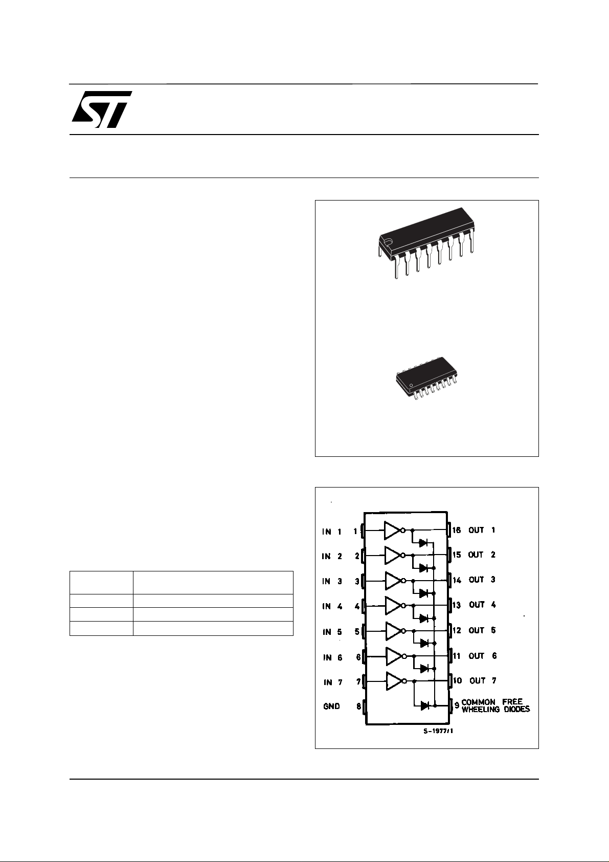
SEVEN DARLINGTON ARRAYS
DIP16
ORDERING NUMBERS:
ULN2001A/2A/3A/4A
SO16
DESCRIPTION
The ULN2001A, ULN2002A, ULN2003 and
ULN200 4A are high volta ge, high cu rrent da rlington
arrays each containing seven open collector darlington pairs with common emitters. Each channel
rated at 500m A and can wi thstand p eak c urre nts of
600mA. Sup pression dio des are inc luded for indu ctive lo ad dr iv ing and the in put s a re pinned oppo si te
the outputs t o s im pli fy board layout.
The four vers ions interface to all com mon logic families :
ULN2001A General Purpose, DTL, TTL, PMOS,
CMOS
ULN2002A 14-25V PMOS
ULN2003A 5V TTL, CMOS
ULN2004A 6–15V CMOS, PMOS
These versatile d evices are usef ul for driv ing a wide
range of loads including solenoids, relays DC motors, LED displays filament lamps, thermal printheads and high power buffer s .
The ULN2001A/2002A/2003A and 2004A are supplied in 16 pin plastic DIP packages with a copper
leadframe to reduce thermal resistance. They are
available also in small outline package (SO-16) as
ULN2001D/2002D/2003D/2004D.
ORDERING NUMBERS:
PIN CONNECTION
ULN2001D/ 2D/ 3D/4 D
February 2002
1/8
ULN2001A - ULN2002A - ULN2003A - ULN2004A
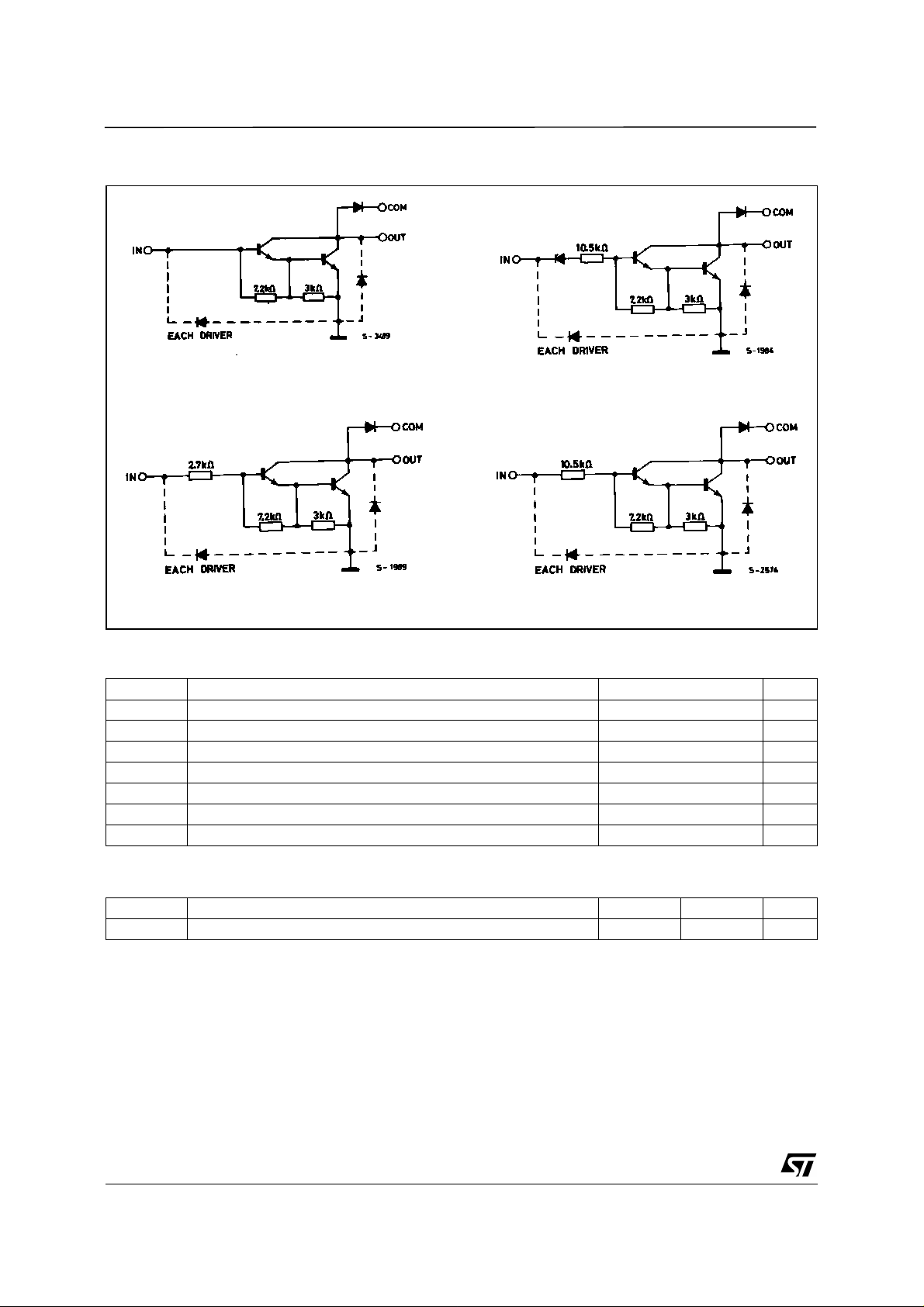
SCHEMATIC DIAGRAM
Series ULN -20 01 A
(each driver)
Series ULN -20 03 A
(each driver)
Series ULN- 20 02 A
(each driver)
Series ULN- 20 04 A
(each driver)
ABSOLUTE MAXIMUM RATIN GS
Symbol Parameter Value Unit
V
o
V
in
I
c
I
b
T
amb
T
stg
T
Output Voltage 50 V
Input Voltage (for ULN2002A/D - 2003A/D - 2004A/D) 30 V
Continuous Collector Current 500 mA
Continuous Base Current 25 mA
Operating Ambient Temperature Range – 20 to 85
Storage Temperature Range – 55 to 150
Junction Temperature 150
j
C
°
C
°
C
°
THERMAL DATA
Symbol Parameter DIP16 SO16 Unit
2/8
R
th j-amb
Thermal Resistance Junction-ambient Max. 70 120
C/W
°
ULN2001A - ULN2002A - ULN2003A - ULN2004A
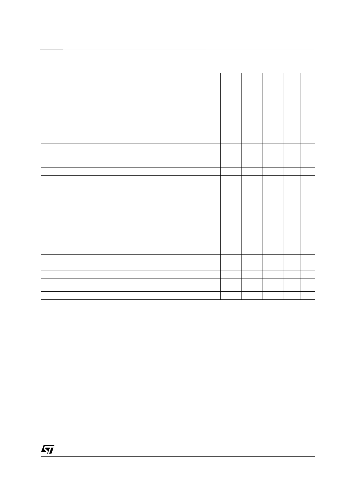
ELECTRICAL CHARACTERISTICS (T
= 25oC unless otherwise specified)
amb
Symbol Parameter Test Conditions Min. Typ. Max. Unit Fig.
I
CEX
V
CE(sat )
I
i(on)
I
i(off)
V
i(on)
Output Leakage Current VCE = 50V
= 70°C, VCE = 50V
T
amb
T
= 70°C
amb
for ULN2002A
= 50V, Vi = 6V
V
CE
for ULN2004A
VCE = 50V, Vi = 1V
Collector-emitter Saturation
Voltage
IC = 100mA, IB = 250µA
= 200 mA, IB = 350µA
I
C
IC = 350mA, IB = 500µA
Input Current for ULN2002A, Vi = 17V
for ULN2003A, Vi = 3.85V
= 5V
i
Input Current T
for ULN2004A, V
Vi = 12V
= 70°C, IC = 500µA5065
amb
Input Voltage VCE = 2V
for ULN2002A
IC = 300mA
0.9
1.1
1.3
0.82
0.93
0.35
1
50
100
500
500
1.1
1.3
1.6
1.25
1.35
0.5
1.45
13
A
µ
A
µ
A
µ
A
µ
V
V
V
mA
mA
mA
mA
A4
µ
V5
for ULN2003A
= 200mA
h
FE
C
i
t
PLH
t
PHL
I
R
V
F
I
C
IC = 250mA
= 300mA
I
C
for ULN2004A
IC = 125mA
= 200mA
I
C
IC = 275mA
IC = 350mA
DC Forward Current Gain for ULN2001A
= 2V, IC = 350mA 1000 2
V
CE
Input Capacitance 15 25 pF
Turn-on Delay Time 0.5 Vi to 0.5 V
Turn-off Delay Time 0.5 Vi to 0.5 V
o
o
0.25 1
0.25 1
Clamp Diode Leakage Current VR = 50V
= 70°C, VR = 50V
T
amb
Clamp Diode Forward Voltage IF = 350mA 1.7 2 V 7
2.4
2.7
3
5
6
7
8
50
100
s
µ
s
µ
A
µ
A66
µ
1a
1a
1b
1b
2
2
2
3
3
3
3
3/8
 Loading...