

Datasheet STPS3045CW, STPS3045CT, STPS3045CP, STPS3045CG Datasheet (SGS Thomson Microelectronics)
MAIN PRODUCTCHARACTERISTICS
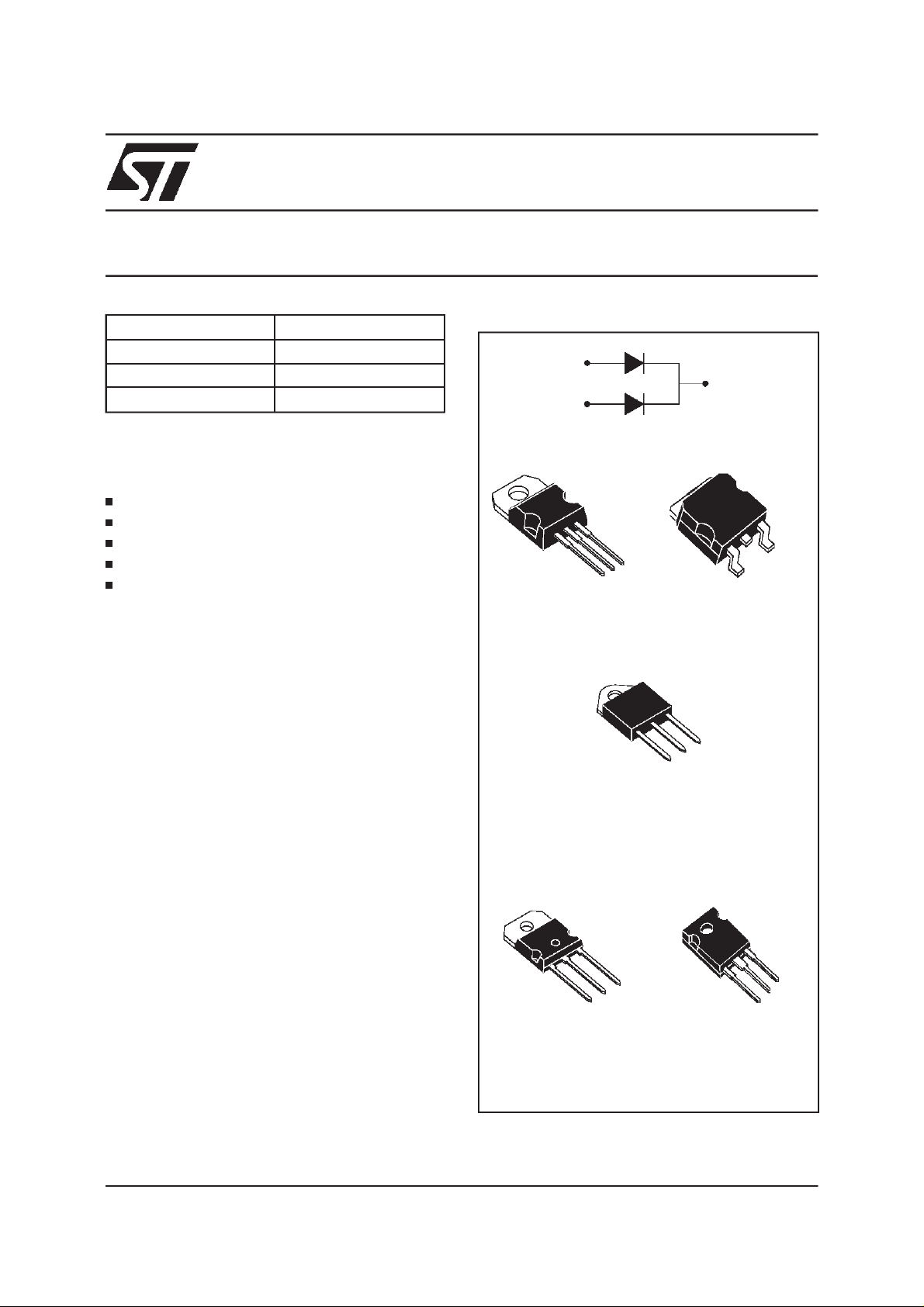
STPS3045CT/CG/CP/CPI/CW
POWER SCHOTTKY RECTIFIER
I
F(AV)
V
RRM
2 x 15 A
45 V
Tj (max) 175°C
V
F
0.57V
FEATURES AND BENEFITS
VERYSMALLCONDUCTION LOSSES
NEGLIGIBLESWITCHINGLOSSES
EXTREMELYFAST SWITCHING
LOWTHERMALRESISTANCE
INSULATEDPACKAGE:TOP-3I
Insulatingvoltage = 2500VRMS
Capacitance= 12pF
DESCRIPTION
Dualcenter tapSchottkyrectifiersuited forSwitchModePowerSupplyandhighfrequencyDC to DC
converters.
2
Packaged either in TO-220AB, D
PAK, TO-247,
SOT93 or TOP-3I, this device is especially intended for use in low voltage, high frequencyinverters, free wheeling and polarity protection
applications.
A1
A2
TO-220AB
STPS3045CT
K
A2
K
A1
A1
Insulated
TOP-3I
STPS3045CPI
K
A2
A1
2
PAK
D
STPS3045CG
A2
K
June 1999 - Ed: 4B
A1
SOT-93
STPS3045CP
A2
K
A2
K
A1
TO-247
STPS3045CW
1/9
STPS3045CT/CG/CP/CPI/CW
ABSOLUTE RATINGS
(limitingvalues, per diode)
Symbol Parameter Value Unit
V
RRM
I
F(RMS)
I
F(AV)
Repetitivepeak reversevoltage 45 V
RMSforward current 30 A
Averageforwardcurrent
δ =0.5
TO-220AB
2
D
PAK
Tc = 155°C Per diode
Per device
15
30
SOT-93
TO-247
TOP-3I Tc = 150°C
I
FSM
I
RRM
Surgenon repetitive forwardcurrent tp = 10 ms sinusoidal 220 A
Repetitivepeak reversecurrent tp = 2 µs square
1A
F = 1kHz
I
RSM
Nonrepetitivepeak reversecurrent
tp = 100µs square
3A
Tstg Storagetemperaturerange -65 to +175°C
Tj Maximumoperatingjunction temperature* 175 °C
dV/dt Criticalrateof rise of reversevoltage 10000 V/µs
*:
dPtot
dTj
<
1
Rth(j−a
thermal runawayconditionfor a diode on its own heatsink
)
A
THERMAL RESISTANCES
Symbol Parameter Value Unit
R
R
th (j-c)
th (c)
Junctionto case
TO-220AB
2
PAK
D
SOT-93
TO-247
TOP-3I
TO-220AB
2
PAK
D
Per diode
Total
Per diode
Total
Per diode
Total
Coupling 0.10
1.60
0.85
1.5
0.8
2.2
1.6
°C/W
SOT-93
TO-247
TOP-3I
Coupling 1.0
Whenthe diodes1 and 2 are usedsimultaneously:
∆ Tj (diode1) =P (diode1) x R
(perdiode) + P (diode 2)x R
th(j-c)
th(c)
2/9
STPS3045CT/CG/CP/CPI/CW
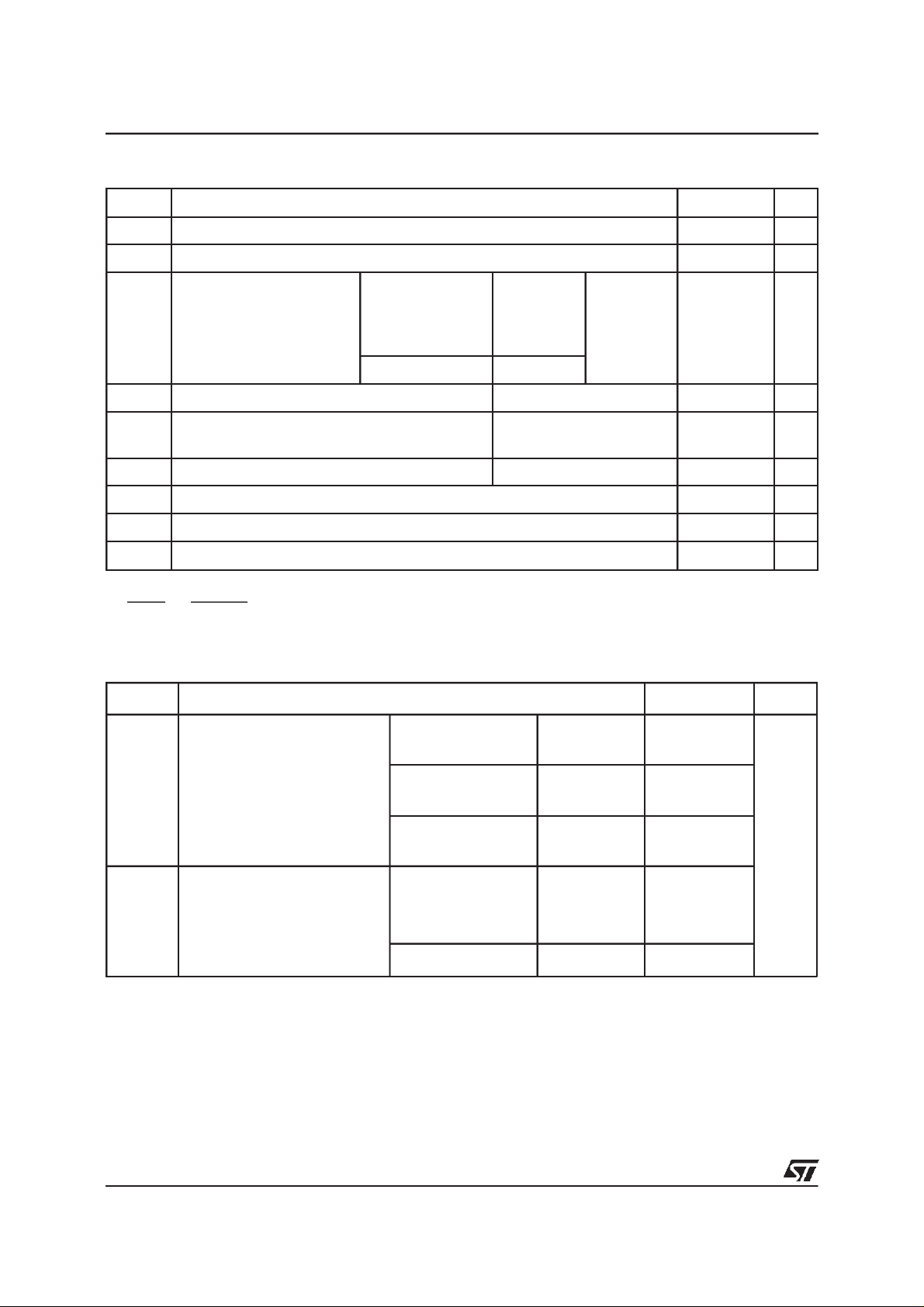
STATICELECTRICAL CHARACTERISTICS
(Perdiode)
Symbol Parameter TestsConditions Min. Typ. Max. Unit
* Reverseleakage current Tj = 25°CV
I
R
R=VRRM
200 µA
Tj = 125°C1140mA
V
* Forward voltagedrop Tj = 125°CI
F
Tj = 25°CI
Tj = 125°CI
= 15 A 0.5 0.57 V
F
= 30 A 0.84
F
= 30 A 0.65 0.72
F
Pulse test : * tp = 380 µs, δ <2%
To evaluatethe conductionlossesuse thefollowingequation:
P = 0.42x I
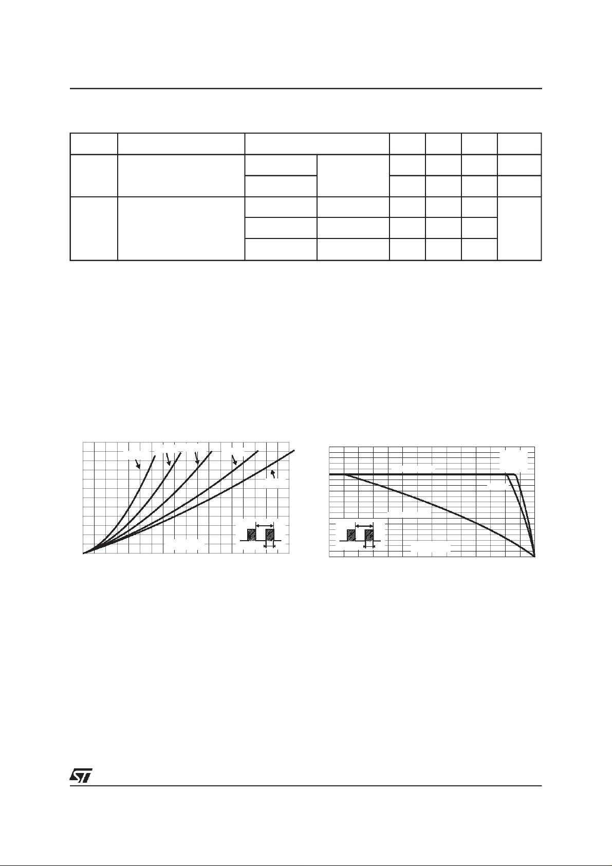
Fig. 1:
Average forward power dissipationversus
averageforwardcurrent(per diode).
F(AV)
+0.01I
F2(RMS)
Fig. 2: Average current versus ambient
temperature(δ=0.5,per diode).
PF(av)(W)
12
10
8
δ = 0.05
δ = 0.1
δ = 0.2
δ= 0.5
δ =1
6
4
T
2
0
IF(av)(A)
024681012141618
δ
=tp/T
tp
IF(av)(A)
20
18
16
14
12
Rth(j-a)=Rth(j-c)
TOP-3I
TO-220AB
SOT-93
TO-247
D P
10
8
6
Rth(j-a)=15°C/W
T
4
2
=tp/T
δ
0
0 25 50 75 100 125 150 175
tp
Tamb(°C)
AK
3/9

STPS3045CT/CG/CP/CPI/CW
Fig.3-1:
versus overload duration (maximum values, per
diode)(TO-220AB, D
Nonrepetitivesurgepeak forwardcurrent
2
PAK,SOT-93 and TO-247).
IM(A)
200
180
160
140
120
100
80
60
IM
40
20
0
1E-3 1E-2 1E-1 1E+0
δ=0.5
t
t(s)
Tc=75°C
Tc=100°C
Tc=125°C
Fig. 4: Relative variation of thermal transient
impedancejunction to caseversuspulse duration.
Zth(j-c)/Rth(j-c)
1.0
0.8
δ = 0.5
0.6
0.4
δ = 0.2
δ = 0.1
0.2
Single pulse
0.0
1E-4 1E-3 1E-2 1E-1 1E+0
tp(s)
δ
=tp/T
T
tp
Fig.3-2:
Nonrepetitivesurgepeak forwardcurrent
versus overload duration (maximum values, per
diode)(TOP-3I).
IM(A)
160
140
120
100
80
60
40
IM
20
0
1E-3 1E-2 1E-1 1E+0
Fig. 5:
δ=0.5
t
t(s)
Reverse leakage current versus reverse
Tc=75°C
Tc=100°C
Tc=125°C
voltageapplied (typicalvalues,per diode).
IR(µA)
5E+4
1E+4
1E+3
1E+2
1E+1
1E+0
0 5 10 15 20 25 30 35 40 45
Tj=150°C
Tj=125°C
Tj=100°C
Tj=75°C
Tj=50°C
Tj=25°C
VR(V)
Fig. 6:
Junction capacitance versus reverse
voltageapplied(typical values,per diode).
C(pF)
2000
1000
500
200
VR(V)
100
12 51020 50
4/9
F=1MHz
Tj=25°C
Fig. 7:
Forward voltage drop versus forward
current(maximum values,perdiode).
IFM(A)
200
100
10
1
0.0 0.2 0.4 0.6 0.8 1.0 1.2 1.4 1.6 1.8
Typicalvalues
Tj=125°C
Tj=25°C
Tj=125°C
VFM(V)

PACKAGEMECHANICAL DATA
TO-220AB
H2
Dia
L5
L6
L2
F2
F1
F
G1
G
L9
L4
STPS3045CT/CG/CP/CPI/CW
DIMENSIONS
REF.
A 4.40 4.60 0.173 0.181
A
C
C 1.23 1.32 0.048 0.051
D 2.40 2.72 0.094 0.107
E 0.49 0.70 0.019 0.027
L7
F 0.61 0.88 0.024 0.034
F1 1.14 1.70 0.044 0.066
F2 1.14 1.70 0.044 0.066
D
G 4.95 5.15 0.194 0.202
G1 2.40 2.70 0.094 0.106
H2 10 10.40 0.393 0.409
L2 16.4typ. 0.645typ.
M
E
L4 13 14 0.511 0.551
L5 2.65 2.95 0.104 0.116
L6 15.25 15.75 0.600 0.620
L7 6.20 6.60 0.244 0.259
L9 3.50 3.93 0.137 0.154
M 2.6 typ. 0.102typ.
Diam. 3.75 3.85 0.147 0.151
Millimeters Inches
Min. Max. Min. Max.
5/9

STPS3045CT/CG/CP/CPI/CW
PACKAGEMECHANICAL DATA
2
PAK
D
E
L2
L
L3
B2
B
G
* FLAT ZONE NOLESSTHAN 2mm
C2
A1
M
DIMENSIONS
REF.
A
Millimeters Inches
Min. Max. Min. Max.
A 4.40 4.60 0.173 0.181
A1 2.49 2.69 0.098 0.106
A2 0.03 0.23 0.001 0.009
D
B 0.70 0.93 0.027 0.037
B2 1.14 1.70 0.045 0.067
C 0.45 0.60 0.017 0.024
C2 1.23 1.36 0.048 0.054
C
R
D 8.95 9.35 0.352 0.368
E 10.00 10.40 0.393 0.409
G 4.88 5.28 0.192 0.208
A2
L 15.00 15.85 0.590 0.624
L2 1.27 1.40 0.050 0.055
*
V2
L3 1.40 1.75 0.055 0.069
M 2.40 3.20 0.094 0.126
R 0.40typ. 0.016 typ.
V2 0° 8° 0° 8°
FOOTPRINT DIMENSIONS (in millimeters)
16.90
10.30
1.30
8.90
3.70
5.08
6/9

PACKAGEMECHANICAL DATA
TO-247
V
V
H
L5
L
F2
F4
L1
F3
L3
F1
V2
F(x3)
G
==
Dia.
L4L2
D
ME
A
STPS3045CT/CG/CP/CPI/CW
DIMENSIONS
REF.
A 4.85 5.15 0.191 0.203
D 2.20 2.60 0.086 0.102
E 0.40 0.80 0.015 0.031
F 1.00 1.40 0.039 0.055
F1 3.00 0.118
F2 2.00 0.078
F3 2.00 2.40 0.078 0.094
F4 3.00 3.40 0.118 0.133
G 10.90 0.429
H 15.45 15.75 0.608 0.620
L 19.85 20.15 0.781 0.793
L1 3.70 4.30 0.145 0.169
L2 18.50 0.728
L3 14.20 14.80 0.559 0.582
L4 34.60 1.362
L5 5.50 0.216
M 2.00 3.00 0.078 0.118
V5° 5°
V2 60° 60°
Dia. 3.55 3.65 0.139 0.143
Millimeters Inches
Min. Typ. Max. Min. Typ. Max.
7/9

STPS3045CT/CG/CP/CPI/CW
PACKAGE MECHANICAL DATA
SOT-93
DIMENSIONS
REF.
Millimeters Inches
Min. Typ. Max. Min. Typ. Max.
A 4.70 4.90 1.185 0.193
C 1.90 2.10 0.075 0.083
D 2.50 0.098
D1 2.00 0.078
E 0.50 0.78 0.020 0.031
F 1.10 1.30 0.043 0.051
F3 1.75 0.069
F4 2.10 0.083
G 10.80 11.10 0.425 0.437
H 14.70 15.20 0.279 0.598
L 12.20 0.480
L2 16.20 0.638
L3 18.0 0.709
L5 3.95 4.15 0.156 0.163
L6 31.00 1.220
O 4.00 4.10 0.157 0.161
8/9

PACKAGEMECHANICALDATA
TOP-3I (isolated)
STPS3045CT/CG/CP/CPI/CW
DIMENSIONS
REF.
A 4.4 4.6 0.173 0.181
B 1.45 1.55 0.057 0.061
C 14.35 15.60 0.565 0.614
D 0.5 0.7 0.020 0.028
E 2.7 2.9 0.106 0.114
F 15.8 16.5 0.622 0.650
G 20.4 21.1 0.815 0.831
H 15.1 15.5 0.594 0.610
J 5.4 5.65 0.213 0.222
K 3.4 3.65 0.134 0.144
L 4.08 4.17 0.161 0.164
P 1.20 1.40 0.047 0.055
R 4.60 0.181
Millimeters Inches
Min. Typ. Max. Min. Typ. Max.
Type Marking Package Weight Base qty Deliverymode
STPS3045CT STPS3045CT TO-220AB 2.23 g. 50 Tube
STPS3045CG STPS3045CG D
STPS3045CG-TR STPS3045CG D
2
PAK 1.48g. 50 Tube
2
PAK 1.48g. 1000 Tape& reel
STPS3045CP STPS3045CP SOT-93 3.97g. 30 Tube
STPS3045CPI STPS3045CPI TOP-3I 4.46 g. 30 Tube
STPS3045CW STPS3045CW TO-247 4.36 g. 30 Tube
Coolingmethod:by conduction(C)
Recommendedtorquevalue(SOT-93,TOP-3I,TO-247):0.8 N.m.
Recommendedtorquevalue(TO-220AB):0.55N.m.
Maximumtorquevalue(SOT-93, TOP-3I,TO-247): 1.0 N.m.
Maximumtorquevalue(TO-220AB): 0.7 N.m.
Epoxymeets UL94,V0
Informationfurnishedis believed tobe accurate andreliable. However,STMicroelectronics assumes noresponsibilityfortheconsequences of
use of such information nor forany infringementof patents or otherrights of thirdparties which mayresult fromits use. No licenseis granted by
implication or otherwise under any patent or patent rights of STMicroelectronics.Specificationsmentioned in this publication are subject to
change without notice.This publication supersedes and replacesall information previously supplied.
STMicroelectronics products are not authorized foruse as critical components in life support devices or systems without express writtenapproval of STMicroelectronics.
The ST logo is a registered trademarkof STMicroelectronics
1999 STMicroelectronics - Printed inItaly -All rights reserved.
STMicroelectronics GROUP OF COMPANIES
Australia -Brazil - China - Finland - France - Germany - Hong Kong - India - Italy - Japan - Malaysia
Malta - Morocco - Singapore - Spain - Sweden - Switzerland - United Kingdom - U.S.A.
http://www.st.com
9/9
 Loading...