

LCP3121
ApplicationSpecific Discretes
A.S.D.
FEATURESAND BENEFITS
UNIDIRECTIONAL OVERVOLTAGE SUPPRESSOR PROGRAMMABLE BY VOLTAGE
ANDCURRENT:
PROGRAMMABLE BREAKDOWN VOLTAGE
UP TO100V.
PROGRAMMABLE CURRENT LIMITATION
FROM120mATO600mA.
MULTI-LINE PROTECTION MODE : ONE DEVICECANPROTECT SEVERALLINES.
HIGH SURGECURRENTCAPABILITY:
=100Afor 10/1000 µs.
I
PP
DESCRIPTION
Dedicated to the protection of sensitive telecom
equipment, the LCP3121 provides protection
which can be programmed by both voltage and
current.
Thebreakdownvoltagecanbe easilyprogrammed
by usingan externalzenerdiode.
Theprotectionfunctionprogrammedbythecurrent
is achievedwith the use of a resistorbetween the
gate andthe cathode.The value of the resistorwill
determine the level of the desired current before
the triggeringof thedevice.
A multipleprotectionmodeis alsoperformedwhen
using several diodesproviding each line interface
with an optimizedprotectionlevel.
If desired,abidirectionalprotectionfunctioncanbe
achievedby the use of twoLCP3121.
COMPLIESWITHTHEFOLLOWINGSTANDARDS:
CCITTK20 : 10/700µs 1kV
5/310µs 25A
VDE0433: 10/700µs 2kV
5/310µs 50A
VDE0878: 1.2/50µs 1.5kV
1/20µs 40A
FCCpart68 : 2/10µs 2.5kV
2/10µs 200A(*)
BELLCORE
TR-NWT-001089: 2/10µs 2.5kV
2/10µs 200A(*)
BELLCORE
TR-NWT-000974:
(*)with series resistors or PTC.
TM: ASD is trademarks of SGS-THOMSON Microelectronics.
September 1998 - Ed: 3
10/1000µs 1kV
10/1000µs 100A
OVERVOLTAGE AND OVERCURRENT
PROTECTION FOR TELECOM LINE
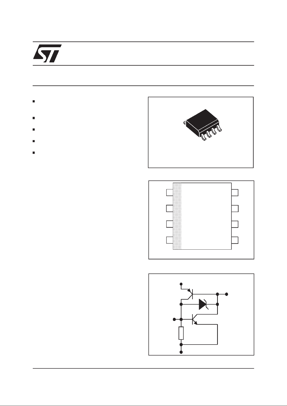
SO8
PIN-OUTCONFIGURATION
1
C
Gn
2
Gp
3
C
4
Allcathodpins must be externallyconnected
FUNCTIONAL DIAGRAM
A
Gp
Gn
C
C
8
7
A
6
A
C
5
1/6
LCP3121
ABSOLUTE MAXIMUM RATINGS(T
amb
=25°C)
Symbol Parameter Value Unit
I
PP
I
TSM
V
V
T
T
T
Note 1 : Pulse waveform :
Peakpulse current(see note 1) 10/1000µs 100 A
Nonrepetitivesurgepeakon-statecurrent
(F= 50Hz)
MaximumvoltagebetweenA andC
AC
MaximumvoltagebetweenG (Gnor Gp)and A
GA
Storagetemperaturerange
stg
Maximumjunction temperature
j
Maximumleadtemperaturefor soldering during10s 260 °C
L
10/1000µst
=10µst
r
=1000µs
p
tp= 10ms
t=1s
%I
PP
100
50
0
16
8
100
80
- 40 to + 150
150
t
t
p
r
t
A
V
°C
THERMALRESISTANCE
Symbol Parameter Value Unit
R
th (j-a)
ELECTRICALCHARACTERISTICS(T
Junctionto ambient 170 °C/W
=25°C)
amb
Symbol Parameter
V
V
V
I
I
I
V
C
V
I
I
Stand-offvoltage
RM
Breakdownvoltage
BR
Breakovervoltage
BO
Holdingcurrent
I
H
Breakovercurrent
BO
Leakagecurrentat V
RM
I
Leakagecurrentat V
R
Peakpulse current
PP
Continuousreversevoltage
R
Off-statecapacitance
off
Gatevoltage
G
Gptriggeringcurrent
GP
Gntriggeringcurrent
GN
RM
R
I
PP
I
BO
I
H
V
R
I
RM
V
V
BR
I
R
RM
V
BO
2/6

LCP3121
1 - OPERATIONWITHOUTGATE(T
amb
=25°C)
Symbol Testconditions Min. Max. Unit
I
RM
I
R
V
BR
I
BO
V
BO
I
H
CV
2 - OPERATIONWITHGATE
VRM=60V
V
=90V
RM
5
8
atVR= 180V 50 µA
at1mA 100 V
80 500 mA
Measuredat 50Hz 180 V
Seethe functionaltestcircuit 100 mA
=-5V F=1MHz 100 pF
R
=25°C)
(T
amb
Symbol Testconditions Min. Max. Unit
V
G
IGATE=200mA (for eigherGnor Gp) 0.6 1.8 V
note1
I
GP
I
GN
V
Anode-cathode
V
Anode-cathode
=60V 180 mA
=60V 80 200 mA
µA
Note 1: VG=VGN, measured between Gn and cathode
VG=VGP, measuredbetween Gpand anode
3/6

LCP3121
FUNCTIONAL HOLDINGCURRENT(IH) TEST CIRCUIT : GO-NOGOTEST
R
D.U.T
BAT
V = -48 V
-VP
Surge
generator
Thisis aGO-NOGOtestwhichallows to confirmtheholdingcurrent(I
TESTPROCEDURE:
- Adjustthecurrent levelat the I
- FiretheD.U.T. with a surgecurrent: I
valueby short circuitingtheD.U.T.
H
= 10A, 10/1000µs.
PP
- TheD.U.T. will come back to the off-statewithin a durationof 50msmax.
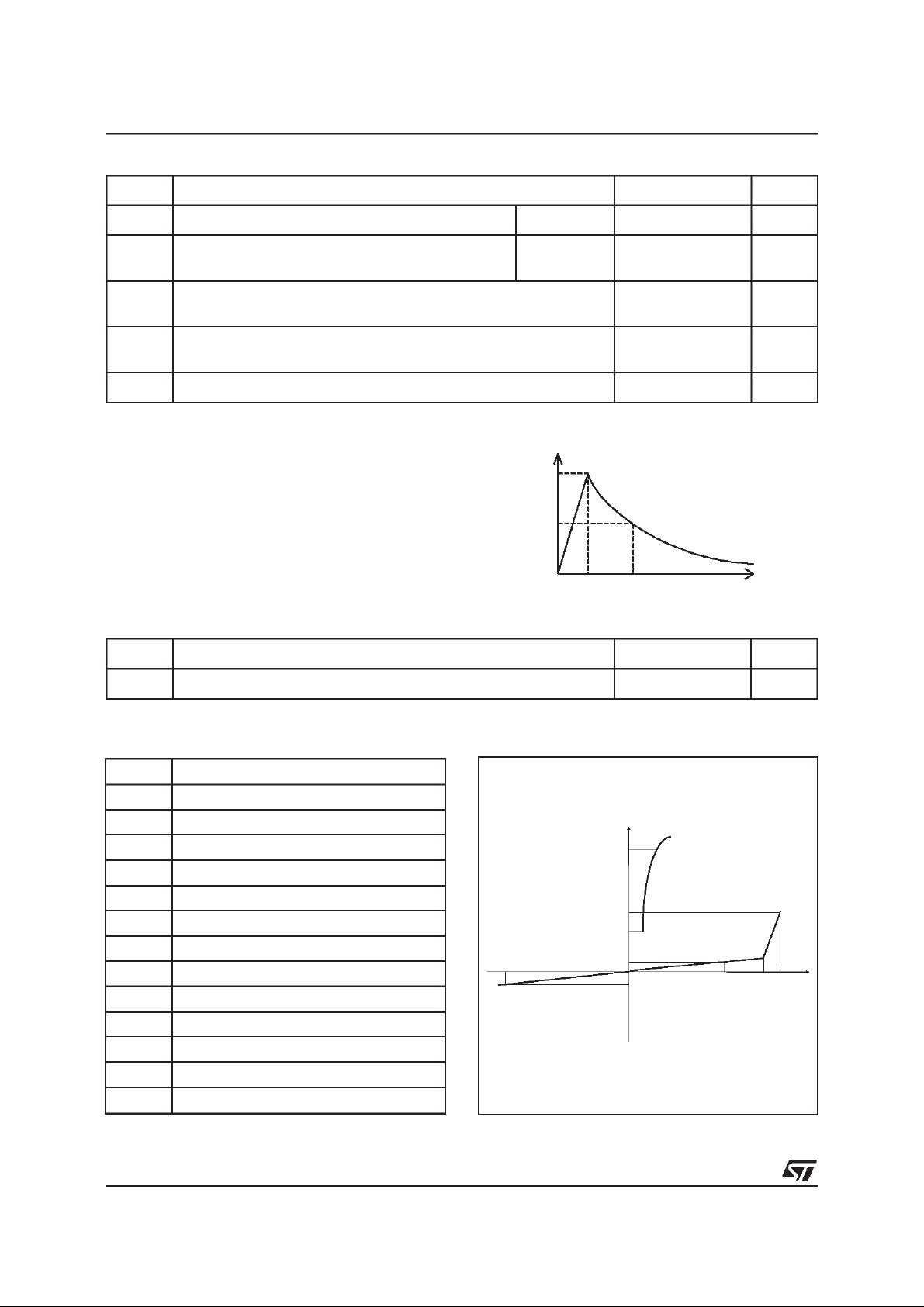
Fig. 1 : Maximum non repetitive surge peak-onstate currentversus overloadduration.
ITSM (A)
20
18
16
14
12
10
8
6
4
2
0
0.01 0.10 1 10 100 1000
t(s)
F=50Hz
Tj initial = 25°c
Fig.2 :Relativevariationof holdingcurrentversus
junctiontemperature(typicalvalues).
IH [Tj] / IH [Tj=25°C]
1.4
1.2
1.0
0.8
0.6
0.4
0.2
0.0
-40 -20 0 20 40 60 80 100 120
) levelin a functionaltestcircuit.
H
Tj(°C)
4/6

APPLICATIONEXAMPLES
LCP3121
Application1 :
CommonprotectionforSLIC
withoutintegratedringgenerator
4*SMBYW01-200
4*SMBYW01-200
Gn
C
LCP3121
Application2 :
Commonprotection for SLIC with
integratedring generator
-Vbat
TIP
SLIC
RING
-Vbat
TIP
SLIC
RING
-Vbat
A
4*SMBYW01-200
4*SMBYW01-200
+Vbat
C
LCP3121
Gp
A
Gn
C
LCP3121
-Vbat +Vbat
TIP
SLIC
L3000N
RING
-Vbat +Vbat
TIP
SLIC
L3000N
RING
-Vbat
A
Application3 :
4*SMBYW01-200
TypicalSLIC protection
LCP3121
A
C
Gn
-Vbat
TIP
RING
-Vbat
SLIC
Application4 : Protectionprogrammedby current
I
T
+
LCP3121
A
Gn
C
Protec ted
Circuit
-
Ra
V
G
G
Ra
I=I +
T
CURRENT TOLERANCE
R
a
Ω
(+/-5%)
4.7
5.6
6.8
8.2
10
12
I
T
mA
min
202
182
164
150
137
128
I
T
mA
max
603
538
479
431
388
358
5/6

LCP3121
ORDERCODE
LCP 31 2 1 RL
LINECARD
PROTECTION
NUMECALCODE
PACKAGEMECHANICAL DATA
SO8Plastic
VERSION
PACKAGING:
RL= tapeand reel.
= tube.
PACKAGE:
1 = SO8.
DIMENSIONS
REF.
Millimetres Inches
Min. Typ. Max. Min. Typ. Max.
A 1.75 0.069
a1 0.1 0.25 0.004 0.010
a2 1.65 0.065
b 0.35 0.48 0.014 0.019
b1 0.19 0.25 0.007 0.010
C 0.50 0.020
c1 45°(typ)
D 4.8 5.0 0.189 0.197
E 5.8 6.2 0.228 0.244
e 1.27 0.050
e3 3.81 0.150
F 3.8 4.0 0.15 0.157
L 0.4 1.27 0.016 0.050
M 0.6 0.024
S8°(max)
MARKING
Package Type Marking
SO8 LCP3121 CP3121
Informationfurnishedis believed to be accurate and reliable.However,STMicroelectronics assumes no responsIbilityfor the consequencesof
use of such information nor forany infringementof patents orother rights of third parties which may result from its use.No license is grantedby
implication or otherwise under any patent or patent rights of STMicroelectronics. Specifications mentioned in this publication are subject to
change without notice.This publication supersedes andreplacesall information previously supplied.
STMicroelectronics products are not authorized for use as critical components in life support devices or systems without express writtenapproval of STMicroelectronics.
The ST logo is a registered trademarkof STMicroelectronics
1998 STMicroelectronics - Printed in Italy - Allrights reserved.
STMicroelectronics GROUP OF COMPANIES
Australia - Brazil - Canada -China - France - Germany - Italy - Japan -Korea - Malaysia - Malta - Mexico - Morocco -
The Netherlands - Singapore - Spain - Sweden -Switzerland - Taiwan - Thailand - United Kingdom - U.S.A.
http://www.st.com
6/6
Weight=
0.08g
Packaging: Products suppliedin anti-statictubes
or tape andreel.
 Loading...