

SGS Thomson Microelectronics BAS70-07FILM Datasheet
BAS70-07
®
June 1999 - Ed: 2A
SMALL SIGNAL SCHOTTKY DIODE
VERY SMALL CONDUCTION LOSSES
NEGLIGIBLE SWITCHING LOSSES
LOW FORWARD V O LTAGE DROP
LOW THERMAL RE SISTA NCE
EXTREMELY FAST SWITCHING
SURFACE MOUNTED DEVICE
FEATURES AND BENE FITS
Low turn-on and high breakdown voltage diodes
intended for
ultrafast switching and UHF detectors in hybrid micro circuits. Packaged in SOT-143, this device is
intended for surface mounting. Its dual independent diodes configuration makes it very interesting for applications where high integration is
searched.
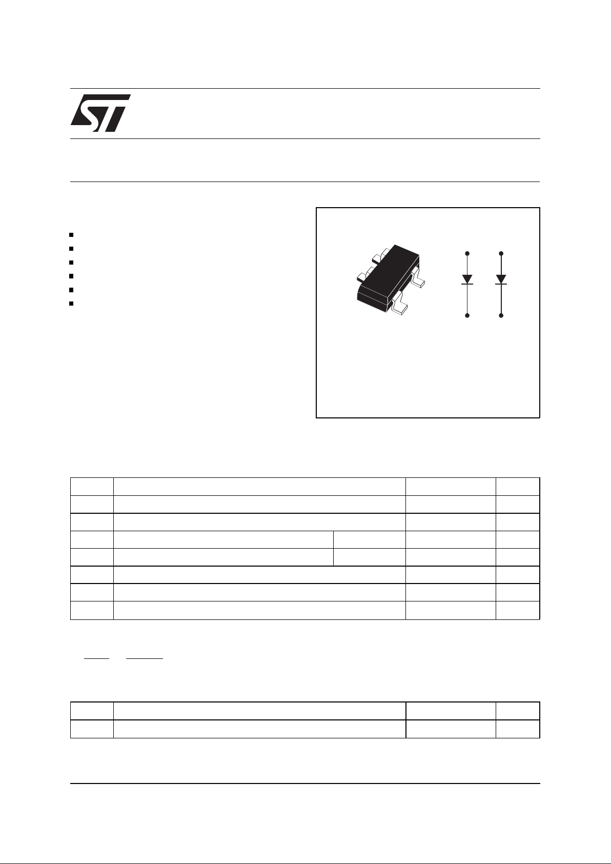
DESCRIPTION
SOT-143
Symbol Parameter Value Unit
V
RRM
Repetitive peak reverse voltage 70 V
I
F
Continuous forward current 15 mA
I
FSM
Surge non repetitive forward current tp = 10ms 1 A
P
tot
Power Dissipation (note 1) T
amb
= 25°C 310 mW
T
stg
Storage temperature range - 65 to +150
°
C
Tj Maximum operating junction temperature * 150
°
C
TL Maximum temperature for soldering during 10s 260
°
C
Note 1:
Ptot is the total dissipation of both diodes.
ABSOLUTE RATINGS
(limiting values)
K1
K2
A1
A2
K1
A1
K2
A2
Symbol Parameter Value Unit
R
th (j-a)
Junction to ambient (*) 400
°
C/W
(*) Mounted on epoxy board with recommended pad layout.
THERMAL RESISTANCE
* :
dPtot
dTj
<
1
Rth(j−a
)
thermal runaway condition for a diode on its own heatsink
1/4
Symbol Tests Conditions Tests Conditions Min. Typ. Max. Unit
V
F
* F orward voltage drop Tj = 25°CI
F
= 1 mA 410 mV
I
F
= 10 mA 750 mV
I
F
= 15 mA 1 V
V
BR
Breakdown voltage Tj = 25°CI
R
= 10 µA70 V
I
R
** Reverse leakage current Tj = 25°CV
R
= 50 V 200 nA
V
R
= 70 V 10
µ
A
STATIC ELECTRICAL CHARACTE RISTICS
Symbol Parameters Tests Conditions Min. Typ. Max. Unit
C Junction capacitance V
R
= 1 V F = 1 MHz 2 pF
t
rr
Revers e recovery time IF = 10 mA Irr = 1 mA
I
R
= 10 mA RL = 100
Ω
5ns
τ
Effective carrier lifetime I
F
= 5 mA Krakauer method 100 ps
DYNAMIC CHARACTERISTICS
(Tj = 25 °C)
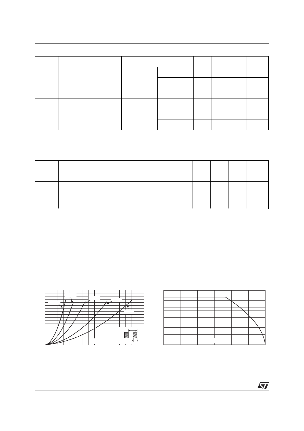
0 1020304050607080
0.00
0.02
0.04
0.06
0.08
0.10
0.12
0.14
0.16
0.18
PF(av)(W)
IF(av) (mA)
δ = 0.2
δ = 0.5
δ = 1
δ = 0.05
δ = 0.1
T
δ
=tp/T
tp
Fig.1 :
Average forward power dissipation versus
average forward current.
0 25 50 75 100 125 150
0
10
20
30
40
50
60
70
80
IF(mA)
Tamb(°C)
Fig.2 :
Continuous forward current versus ambient
temperature.
Pulse test: * tp = 380 µs, δ < 2%
** tp = 5 ms, δ < 2%
BAS70-07
2/4
 Loading...