

Page 1
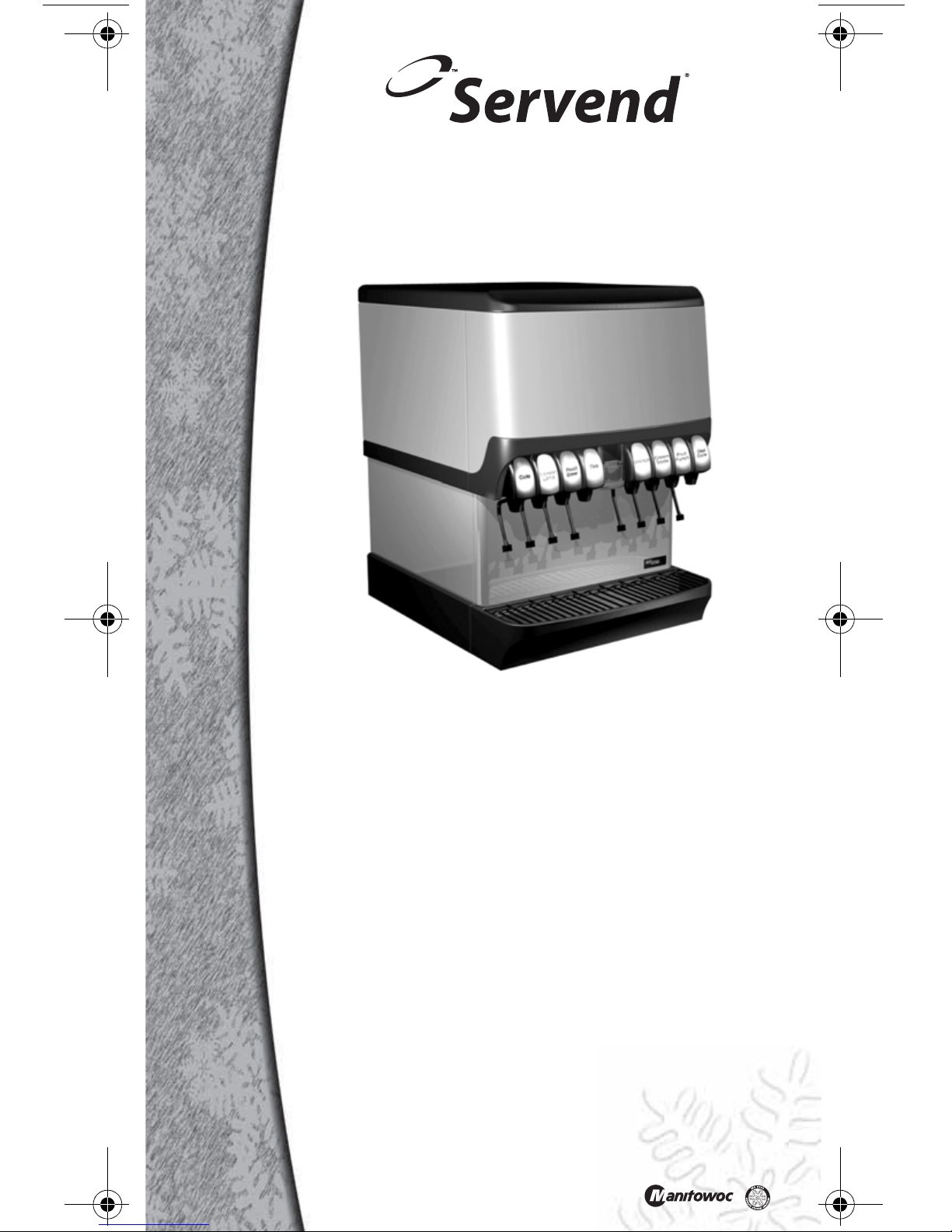
Leader in Ice & Beverage Dispensers
Part Number STH14 9/10
Servend Ice & Beverage
Dispensing Units
Technician’s
Handbook
This manual is updated as new information and models
are released. Visit our website for the latest manual.
www.manitowocfsg.com
Page 2

Page 3

Safety Notices
!
Warning
!
Caution
Important
As you work on Manitowoc equipment, be sure to pay
close attention to the safety notices in this handbook.
Disregarding the notices may lead to serious injury
and/or damage to the equipment.
Throughout this handbook, you will see the following
types of safety notices:
Text in a Warning box alerts you to a potential
personal injury situation. Be sure to read the
Warning statement before proceeding, and work
carefully.
Text in a Caution box alerts you to a situation in
which you could damage the equ ipment. Be sure
to read the Caution statement before proceeding,
and work carefully.
Procedural Notices
As you work on Manitowoc equipment, be sure to read
the procedural notices in this handbook. These notices
supply helpful information which may assist you as
you work.
Throughout this handbook, you will see the following
types of procedural notices:
Text in an Important box provides you with
information that may help you perform a
procedure more efficiently. Disregarding this
information will not cause damage or injury, but it
may slow you down as you work.
Page 4

NOTE: Text set off as a Note provides you with simple,
!
Caution
Important
! Warning
We reserve the right to make product
improvements at any time. Specifications and
design are subject to change without notice.
but useful, extra information about the procedure you
are performing.
Read These Before Proceeding:
Proper installation, care and maintenance are
essential for maximum performance and troublefree operation of your Manitowoc equipment. If
you encounter problems not covered by this
handbook, do not proceed, contact Manitowoc
Foodservice Group. We will be happy to provide
assistance.
Routine adjustments and maintenance
procedures outlined in this handbook are not
covered by the warranty.
PERSONAL INJURY POTENTIAL
Do not operate equipment that has been
misused, abused, neglected, damaged, or
altered/modified from that of original
manufactured specifications.
Page 5

Table of Contents
General Information
Model Numbers . . . . . . . . . . . . . . . . . . . . .9
How to Read a Model Number . . . . . . . . .9
Dispensing Basics . . . . . . . . . . . . . . . . . .10
Accessories . . . . . . . . . . . . . . . . . . . . . . .13
Serial Number Location . . . . . . . . . . . . . . 15
Warranty Information . . . . . . . . . . . . . . . .15
Installation
General . . . . . . . . . . . . . . . . . . . . . . . . . . .17
Dimensions . . . . . . . . . . . . . . . . . . . . . . . .18
Pre-installation Checklist . . . . . . . . . . . . .31
Location . . . . . . . . . . . . . . . . . . . . . . . . . .33
Drains . . . . . . . . . . . . . . . . . . . . . . . . . . . .34
Water Supply . . . . . . . . . . . . . . . . . . . . . . .38
Setting Pressures . . . . . . . . . . . . . . . . . . .39
Component Identification
Typical Systems . . . . . . . . . . . . . . . . . . . . 43
System Components . . . . . . . . . . . . . . . .46
Ice/Beverage and Counter Electric
Dispensers . . . . . . . . . . . . . . . . . . . . . . . .53
Maintenance
Cleaning . . . . . . . . . . . . . . . . . . . . . . . . . .55
Disassembly . . . . . . . . . . . . . . . . . . . . . . .59
Replacement . . . . . . . . . . . . . . . . . . . . . . .79
Sanitizing . . . . . . . . . . . . . . . . . . . . . . . . .82
Shipping, Storage and Reloc a t io n . . . . .87
Operation
Blade Tower Brixing . . . . . . . . . . . . . . . . .89
CEV Electronic Ice & Carbonation Control 90
Flavor Magic Programming . . . . . . . . . . .93
Flav’R-Pic External Programming . . . . . . 97
Flav’R-Pic (FRP-250) Programming . . . .100
Flav’R-Pic (FRP-250) Brixing Procedure 105
FlexTower Programming Modes . . . . . . .115
Adjustments . . . . . . . . . . . . . . . . . . . . . . .120
Part Number STH14 9/10 5
Page 6

Agitation Timer . . . . . . . . . . . . . . . . . . . . 124
Troubleshooting
Checklist . . . . . . . . . . . . . . . . . . . . . . . . . . 125
Liquid Level Control . . . . . . . . . . . . . . . . 137
Diagnosing a Defective Carbonator . . . . 138
Component Specifications
Electrical Requirements . . . . . . . . . . . . . 139
Minimum Circuit Ampacity . . . . . . . . . . . 139
Grounding Instructio ns . . . . . . . . . . . . . . 141
Pump Deck Wiring . . . . . . . . . . . . . . . . . . 143
Water Supply . . . . . . . . . . . . . . . . . . . . . . 144
Charts
Flavor Magic Logic Matrix . . . . . . . . . . . . 147
Flav’R-Pic (FRP-250) Logic Matrix . . . . . 150
Diagrams
Blade Tower Plumbing . . . . . . . . . . . . . . 153
CEV-30i & CEV-30e Plumbing . . . . . . . . . 156
CEV-40i & CEV-40e Plumbing . . . . . . . . . 158
CT-6 Plumbing and Wiring . . . . . . . . . . . 160
CT-8 Plumbing and Wiring . . . . . . . . . . . 161
CF-1522 Plumbing . . . . . . . . . . . . . . . . . . 162
DI-1522 Post-mix Plumbing . . . . . . . . . . 164
DI-1522 Pre-mix Plumbing . . . . . . . . . . . 164
DI/DIL-2323 6 Valve Post-mix Plumbing 165
DI/DIL-2323 8 Valve Post-mix Plumbing &
Variety Valve . . . . . . . . . . . . . . . . . . . . . . 166
DI/DIL-2323 10 Valve Post-mix Plumbing 167
DI/DIL-2323 6 Valve Pre-m i x Plumbing . 168
Flavor Magic Plumbing . . . . . . . . . . . . . . 169
FRP-250 Plumbing Diagram . . . . . . . . . . 170
FRP-250 & FRP-250SCI Tubing Layout . 171
FT-8 Plumbing . . . . . . . . . . . . . . . . . . . . . 172
FT-12 Plumbing . . . . . . . . . . . . . . . . . . . . 172
FlexTower Water Recirculatio n Pump Flow
. . . . . . . . . . . . . . . . . . . . . . . . . . . . . . . . . . 173
FlexTower Water Chiller Flow . . . . . . . . . 173
MDH-302 12 Valve Plumbing . . . . . . . . . . 174
MDH-402 16 Valve Plumbing . . . . . . . . . . 175
6 Part Number STH14 9/10
Page 7

MDH-402 20 Valve Plumbing . . . . . . . . . .176
S/SV150 6 Valve Diagram . . . . . . . . . . . .177
S/SV175 8 Valve Diagram . . . . . . . . . . . .177
S/SV200/250/SV-250QD 8 Valve Diagram 178
S/SV200/250 10 Valve Diagram . . . . . . . .178
Flex Manifold Diagrams . . . . . . . . . . . . . .180
CEV Wiring . . . . . . . . . . . . . . . . . . . . . . . .181
CF Drop-In Series Wiring . . . . . . . . . . . . .187
Drop-in Wiring . . . . . . . . . . . . . . . . . . . . . .188
Flavor Magic Wiring . . . . . . . . . . . . . . . . .192
Flav’R-Pic (FRP-250) Wiring . . . . . . . . . .193
FlexTower Wiring . . . . . . . . . . . . . . . . . . .195
MDH-302 & MDH-402 Wiring . . . . . . . . . . 199
NGF-250 Wiring . . . . . . . . . . . . . . . . . . . . .201
quickdraw Wiring . . . . . . . . . . . . . . . . . . .202
S/SV/SVi Wiring . . . . . . . . . . . . . . . . . . . .203
Selectable Ice Wiring . . . . . . . . . . . . . . . .205
Part Number STH14 9/10 7
Page 8

8 Part Number STH14 9/10
This Page Intentionally Left Blank
Page 9

General Information
S - Ice Dispenser
SV - Ice/Beverage
Dispenser
i - Internal Carb
QD - Quickdraw
Ice Capacity
Model Prefix
Model Suffix
Model Base
SV–250–i
Model Numbers
This manual covers the following models:
CEV-30j CEV-30e CEV-30i
CEV-40e CEV-40i CT-6
CT-8 DI-1522 DI-2323
DIL-2323 FRP-250 FRP-250SCI
FT-8 FT-12 FT-16
M-15 M-45 M-90
MDH-302 MDH-402 MDH-302CI
MDH-302SCI MDH-402CI MDH-402SCI
NGF-250 NGF-250QD S-150
S-200 S-250 SV-150
SV-175 SV-20 0 SV-250
SV-150i SV-175i SV-200i
SV-250i SV-250QD SV-200SCI
SV-250SCI BLADE TOWER FLAVOR MAGIC
How to Read a Model Number
Part Number STH14 9/10 9
Page 10

Manitowoc Foodservice developed this manual as a
reference guide for the service agent and installer of
fountain equipment.
Fountain dispensing is the serving of a beverage (soft
drink, tea, or juice, etc.) from a dispenser that will chill
the product to an acceptable serving temperature for
the consumer.
The beverage, delivery system and dispenser can be
postmix or premix. The system may be an elaborate
system with most of the components in the back of the
store and the dispenser in the front. Fountain systems
could be a simple system with the complete system
under the counter where the dispenser is located.
Our goal is that this manual will remove some of the
confusion, and mystery of beverage dispensing
equipment while providing a general overview of
service to the equipmen t.
Dispensing Basics
WHAT IS CARBONATION
Carbonation is the process of mixing carbon dioxide
gas into a liquid (water). The resulting liquid is called
soda water or carbonated water. The carbon dioxide
gas is the bubbles you see when a carbonated
beverage (like soda) is dispensed.
Most cola, lemon-lime products, etc. are carbonated.
Normally teas, juices, etc. are noncarbonated.
Some beverage technicians refer to noncarbonated
water as sweet water.
WATER CHARACTERISTICS
Water makes up over 80% of the typical finished
beverage. The quality of this primary ingredient is of
utmost importance. You should use regular cold tap
water, not water that has been through a water
softener, conditioner, etc. Any off taste or color should
be treated by proper water filtration.
10 Part Number STH14 9/10
Page 11

WATER FILTERS
It is recommended that proper water filters treat the
water supply for the beverages. There are two basic
filters commonly in use.
1. Pre-filter, or sand filter. This filter removes any
foreign matter from the water down to 25 microns
in size.
2. Carbon or activated charcoal filter is also used.
This filter will reduce chlorine and other
chemicals, off-taste and odor. Some of the higher
quality filters may reduce organic compounds
(bacteria) in the water.
Do not use a filter containing any type of phosphate on
the beverage system. Phosphate as used for scale
reduction will cause the beverage to lose its
carbonation and become “flat” quickly.
WATER PRESSURES
Dynamic (flowing) water pressures to most
carbonators should be a minimum of 40 PSI
(1.38 bar). Water pressure to dispensers for
noncarbonated beverages should be a minimum of
50 pounds (22.7 kg). These pressures are minimum
operating pressures, not static pressure.
SYRUP BASICS
Your concentrated syrup containers should be stored
in a cool dry location that is easily accessible. Any
extremes in temperature can wreak havoc with the
quality of the product. For best results, the syrup
should be maintained in an environment between 40°
and 90°F (4.4° and 32.2°C).
Part Number STH14 9/10 11
Page 12
PREMIX
Premix fountain dispensing consists of a container of
beverage ready for dispensing, beverage delivery
system, carbon dioxide (CO
) propellant, beverage
2
cooling system, and dispenser. We shall discuss each
component of this type of system within the context of
this manual.
The major advantage of a premix system over most
other types is its flexibility . This flexibility is the ability to
go anywhere. Many premix systems will operate
without electric power or separate water supply.
POSTMIX
Postmix fountain dispensing consists of either a tank
(called a Figal) or a box (called a Ba g-i n -Bo x ) of
beverage syrup. The postmix system will also include
the carbonator, fresh water supply, carbon dioxide
(CO
) supply , syrup delivery system, beverage cooling
2
system, and dispenser. We shall discuss each
component of this type of system within the context of
this manual.
The major advantage of the postmix system over most
other systems is the very low cost of delivering a high
quality, fresh beverage to the consumer uti lizing less
floor and storage space for the qu antity of beverages
served.
PIPING
The fountain system is connected together by a series
of tubing or hoses. This tubing is called beverage tube
and is commonly available in 1/4" (0.64 cm), 3/8" (0.95
cm), and 1/2" (1.27 cm) inside diameters. Beverage
tubing is a flexible, high-pressure tubing. This tubing is
capable of withstanding system pressures in excess of
100 PSI (6.9 bar). The beverage tubing may be an
individual line or assembled with many lines of tubing
bundled together.
The beverage tubing is attached to the various
components of the system with barbed stems, nuts,
tees, etc. The tubing is held onto the fittings with small
tube clamps called stepless (Oetiker
®
) clamps. When
attaching the tubing and fitting to a “flared” fitting, the
use of a flare washer is required.
12 Part Number STH14 9/10
Page 13

Several different types of tubing are available for the
beverage industry. If there is any po ssi b ili ty of the
tubing laying in a damp environment, the use of
non-permeable tubing should be used. Tubing is also
available as a single tube or bundled together. Single
tube is available as non-permeable plastic or stainless
steel. Bundled tube is available as plastic only .
Accessories
BAFFLE FOR MANITOWOC® ICE MACHINES
When installing a Manitowoc Ice Machine on a
dispenser, a baf fle kit is required for proper installation.
The baffle kit is designed to prevent ice from lying
against the front of the ice machine, and melting down
the front of the dispenser. There are two different
baffle kits available for “S” series ice machines, one kit
is for the 30" (76.2 cm) wide machine, and the other kit
is for the 22" (55.9 cm) wide machine. There is also a
kit for “Q” series ice machines.
Kits are available through your local distributor. List
prices may be subject to change without notification.
Please call your local parts distributor for current
pricing before ordering.
NOTE: For full information about ice machine
installation, including plumbing lines connections and
electrical requirements, see the ice machine
installation manual.
MANUAL FILL LID FOR DISPENSERS
WITH AN ICE MACHINE
If you are top mounting your dispenser with an ice
machine, you will require a lid for the manual fill area
at the top, front of the dispenser.
If you ordered a dispenser and an ice machine at the
same time, the manual fill lid may be included with the
unit. The manual fill lid can be ordered from your local
distributor.
LEGS
Legs are optional equipment with most MBE
dispensers. Standard legs are 4" (10.2 cm) tall
stainless steel legs. We do not recommend using legs
Part Number STH14 9/10 13
Page 14

when an ice machine is mounted on the dispenser.
The combined weight of the dispenser, ice and ice
machine is more evenly distributed when the base
area of the dispenser is in contact with the countertop.
14 Part Number STH14 9/10
Page 15

Serial Number Location
Label
This number is required when requesting information
from your local distributor. The serial number is listed
on the SERIAL NUMBER DECAL affixed to the
dispenser.
Serial Number Location
Warranty Information
Consult your local MBE Distributor for terms and
conditions of your warranty. Your warranty specifically
excludes all beverage valve brixing, general
adjustments, cleaning, accessories and related
servicing.
Your warranty card must be returned to MBE to
activate the warranty on this equipment. If a warranty
card is not returned, the warranty period can begin
when the equipment leaves the MBE factory.
No equipment may be returned to MBE without a
written Return Materials Authorization (RMA).
Equipment returned without an RMA will be refused at
MBE’s dock and returned to the sender at the sender’s
expense.
Please contact your local MBE distributor for return
procedures.
Part Number STH14 9/10 15
Page 16

16 Part Number STH14 9/10
This Page Intentionally Left Blank
Page 17

Installation
Important
General
These instructions are provided to assist the qualified
installer. Contact your Manitowoc Beverage
Equipment Service Agent or call Manitowoc Beverage
Equipment for information regarding start-up services.
Failure to follow these installation guidel ines may
affect warranty coverage.
Part Number STH14 9/10 17
Page 18

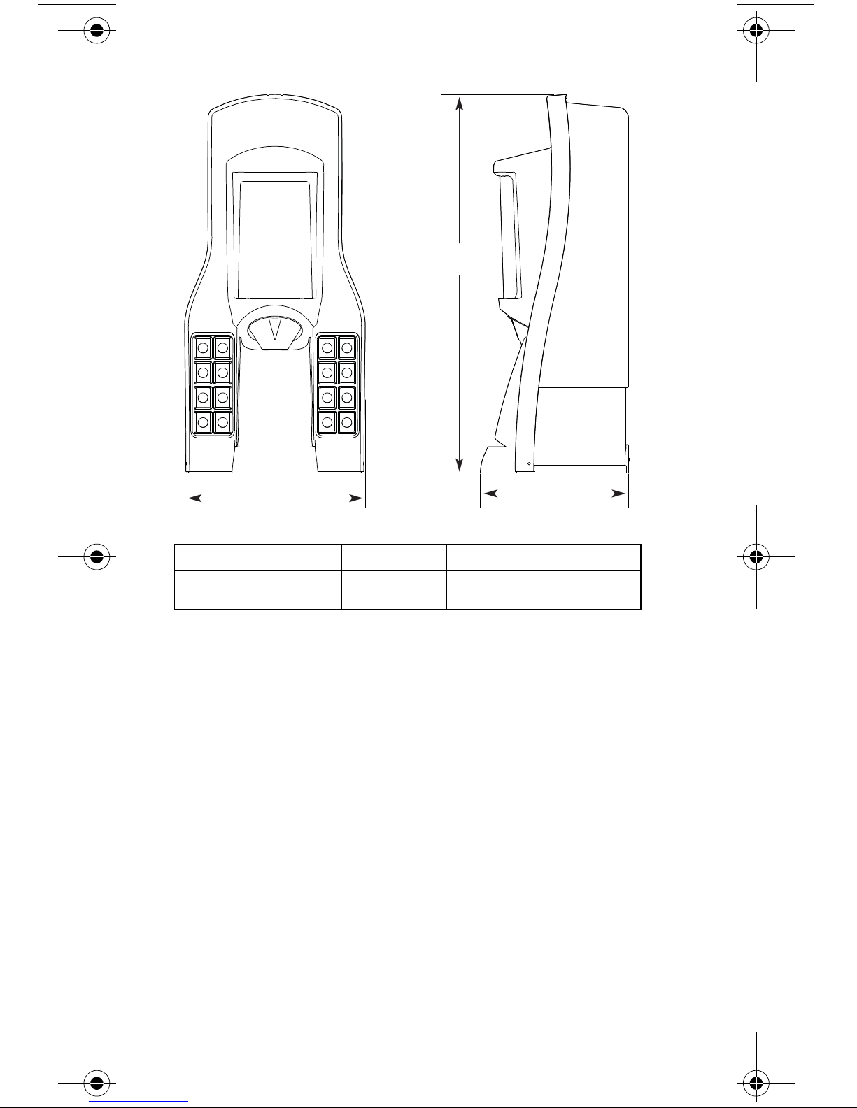
Dimensions
Note: Graphic above is for illustration purposes only, and
may not look like your unit.
A
B
C
D
E
F
G
H
I
ICE/BEVERAGE & COUNTER ELECTRIC
DISPENSER DIMENSIONS
18 Part Number STH14 9/10
Page 19

* C = Valve height using Flomatic Valves.
MODEL A B C* D E F G H I
CEV-30 29.88"
(75.9 cm)
20.50"
(52.7 cm)
11.76"
(29.8 cm)
4.44"
(1 1 .3 cm)
N/A N/A 25.75"
(65.4 cm)
17.00"
(43.1 cm)
17.50"
(44.4 cm)
CEV-40 29.88"
(75.9 cm)
26.00"
(66.0 cm)
11.76"
(29.8 cm)
4.44"
(1 1 .3 cm)
N/A N/A 25.75"
(65.4 cm)
17.00"
(43.1 cm)
23.00"
(58.4 cm)
M-45 24.25"
(61.6 cm)
15.00"
(38.10 cm)
9.75"
(24.8 cm)
4.44"
(1 1 .3 cm)
17.88”
(45.4 cm)
26.37”
(67.0 cm)
28.00”
(71.1 cm)
19.37”
(49.2cm)
12.75”
(32.4 cm)
M-90 32.00" (81.30 cm) 15.00"
(38.10 cm)
9.75"
(24.8 cm)
4.44"
(1 1 .3 cm)
18.00”
(45.7 cm)
26.37”
(67.0 cm)
28.00”
(71.1 cm)
19.37”
(49.2cm)
12.75”
(32.4 cm)
MDH-302
(SCI)
33.00" / 44.00" w/EMerch
(83.8 cm / 111.7 cm)
42.75"
(108.5 cm)
9.94"
(17.6 cm)
4.44"
(1 1 .3 cm)
22.50"
(57.2 cm)
28.00"
(71.1 cm)
30.50"
(77.4 cm)
20.50"
(52.0 cm)
38.75"
(98.4 cm)
MDH-402
(SCI)
32.00" / 44.00" w/EMerch1 /
54.00" w/EMerch2
(81.2 cm / 111.7 cm 137.1 cm)
60.00"
(152.4 cm)
9.94"
(17.6 cm)
4.44"
(1 1 .3 cm)
22.50"
(57.2 cm)
28.00"
(71.1 cm)
30.50"
(77.4 cm)
21.25"
(54.0 cm)
56.50"
(143.6 cm)
S/SV-150 24.81"
(63.0 cm)
23.00"
(58.4 cm)
9.94"
(17.6 cm)
4.44"
(1 1 .3 cm)
22.63"
(57.5 cm)
28.00"
(71.1 cm)
31.13"
(79.1 cm)
20.00"
(50.8 cm)
20.44"
(51.9 cm)
S/SV-175 24.81"
(63.0 cm)
23.00"
(58.4 cm)
9.94"
(17.6 cm)
4.44"
(1 1 .3 cm)
22.63"
(57.5 cm)
28.00"
(71.1 cm)
31.13"
(79.1 cm)
20.00"
(50.8 cm)
22.44"
(57.0 cm)
S/SV-200 34.81"
(88.4 cm)
30.00"
(76.2 cm)
9.94"
(17.6 cm)
4.44"
(1 1 .3 cm)
22.63"
(57.5 cm)
28.00"
(71.1 cm)
31.13"
(79.1 cm)
20.00"
(50.8 cm)
27.44"
(69.7 cm)
S/SV/FRP/
NGF-250
(QD & SCI)
39.81"
(101.1 cm)
30.00"
(76.2 cm)
9.94"
(17.6 cm)
4.44"
(1 1 .3 cm)
22.63"
(57.5 cm)
28.00"
(71.1 cm)
31.13"
(79.1 cm)
20.00"
(50.8 cm)
27.44"
(69.7 cm)
Part Number STH14 9/10 19
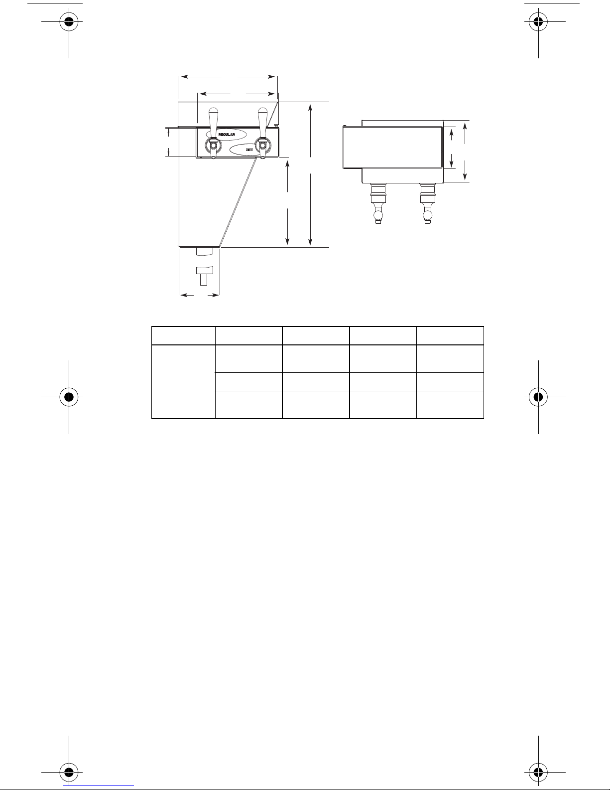
Page 20

DROP-IN & CT DIMENSIONS
A
B
C
D
E
F
G
H
20 Part Number STH14 9/10
Page 21

MODEL A B C* D E F G H
CT-6 N/A N/A 9.50"
(24.2 cm)
14.25"
(36.2 cm)
17.00”
(43.2 cm)
16.38"
(42.8 cm)
N/A 22.50”
(57.2 cm)
CT-8 N/A N/A 9.50"
(24.2 cm)
15.50"
(39.8 cm)
25.00”
(63.5 cm)
23.75"
(60.4 cm)
N/A 22.85”
(58.1 cm)
DI-1522 44.38”
(112.8 cm)
38.38"
(97.5 cm)
9.50"
(24.2 cm)
15.00"
(38.2 cm)
22.38”
(56.9 cm)
16.38"
(42.8 cm)
22.00”
(55.9 cm)
22.00"
(55.9 cm)
DI/DIL-2323 56.75”
(144.2 cm)
46.75"
(118.8 cm)
9.50"
(24.2 cm)
23.00"
(58.5 cm)
33.75”
(85.8 cm)
23.75"
(60.4 cm)
23.00”
(58.5 cm)
23.00"
(58.5 cm)
Part Number STH14 9/10 21
Page 22
FLEXTOWER DIMENSIONS
A
B
C
MODEL A B C
FT-8/12/16 36.00"
(91.5 cm)
14.00"
(35.6 cm)
(24.2 cm)
9.50"
22 Part Number STH14 9/10
Page 23
BLADE TOWER DIMENSIONS
A
B
D
H
G
F
C
E
MODEL A B C D
BLADE
TOWER
17.30"
(44.0 cm)
EFGH
3.29"
(8.4 cm)
11.86"
(30.2 cm)
4.88"
(12.4 cm)
10.75"
(27.3 cm)
7.39"
(18.8 cm)
9.68"
(24.6 cm)
5.00"
(12.7 cm)
Part Number STH14 9/10 23
Page 24
ICE/BEVERAGE & COUNTER ELECTRIC
Minimum Area
for Cutout
Maximum Area
for Cutout
NOTE: Footprint above is for illustration purposes only,
and may not look like the bottom of your unit.
B
A
C
D
DISPENSER FOOTPRINTS
24 Part Number STH14 9/10
Page 25
MODEL
! Warning
Maximum Minimum
ABCD
CEV-30 14.50"
(36.8 cm)
CEV-40 20.00"
(50.8 cm)
M-45 8.00"
(20.3 cm)
M-90 8.00"
(20.3 cm)
MDH-302* 36.75"
(93.3 cm)
MDH-402* 38.75"
(98.4 cm)
S/SV-150 19.00"
(48.3 cm)
S/SV-175 21.00"
(53.3 cm)
S/SV-200
& 250**
26.00"
(66.0 cm)
12.50"
(31.7 cm)
12.50"
(31.7 cm)
12.00"
(30.5 cm)
12.00"
(30.5 cm)
20.50"
(52.1 cm)
20.50"
(52.1 cm)
17.81"
(45.2 cm)
17.81"
(45.2 cm)
17.81"
(45.2 cm)
8.00"
(20.3 cm)
8.00"
(20.3 cm)
8.00"
(20.3 cm)
8.00"
(20.3 cm)
8.00"
(20.3 cm)
8.00"
(20.3 cm)
8.00"
(20.3 cm)
8.00"
(20.3 cm)
8.00"
(20.3 cm)
8.00"
(20.3 cm)
8.00"
(20.3 cm)
12.00"
(30.5 cm)
12.00"
(30.5 cm)
12.00"
(30.5 cm)
12.00"
(30.5 cm)
8.00"
(20.3 cm)
8.00"
(20.3 cm)
8.00"
(20.3 cm)
* Includes models ending in SCI
** Includes NGF, FRP, and models ending in QD or SCI
Cutting the countertop may decrease its strength.
Counter must be braced to support the dispenser
countertop weight plus ice storage capacity and
weight of ice machine, if applicable.
Part Number STH14 9/10 25
Page 26
DROP-IN & CT FOOTPRINTS
DI 1522 cut out depth 22.25" (56.5 cm)
DI/DIL 2323 cut out depth 23.25" (59.1 cm)
DI/DIL 2323 cut out width 23.25" (59.1 cm)
DI 1522 cut out width 15.25" (38.7 cm)
DI/DIL-1522 & 2323
26 Part Number STH14 9/10
Page 27

CT-6
A
B
C
D
E
F
G
H
I
J
K
L
M
Perimeter
of CT-6
Base
Cut Pattern in Counter Top
ABCDE
12.375"
(31.43 cm)
4.625"
(11.75 cm)
0.313"
(0.80 cm)
1.625"
(4.13 cm)
10.50"
(26.67 cm)
FGHIJ
1.50"
(3.81 cm)
1.50"
(3.81 cm)
3.625"
(9.21 cm)
0.25"
(0.64 cm)
1.938"
(4.92 cm)
KLM
1.188"
(3.02 cm)
1.625"
(4.13 cm)
0.313"
(0.80 cm)
Part Number STH14 9/10 27
Page 28

CT-8
A
B
C
D
E
F
G
H
I
J
K
L
M
N
O
P
Perimeter
of CT-8
Base
Cut Pattern in
Counter Top
ABCD
23.25"
(59.1 cm)
20.25"
(51.44 cm)
15.25"
(38.74 cm)
11.25"
(28.58 cm)
EFGH
4.75"
(12.07 cm)
1.75"
(4.45 cm)
1.56"
(3.96 cm)
0.75"
(1.91 cm)
IJKL
1.50"
(3.81 cm)
3.25"
(8.26 cm)
2.50"
(6.35 cm)
22.50"
(57.15 cm)
MNOP
8.00"
(20.32 cm)
1.47"
(3.73 cm)
2.25"
(5.72 cm)
1.56"
(3.96 cm)
28 Part Number STH14 9/10
Page 29

FLEXTOWER FOOTPRINT
AB
C
D
E
F
G
Supply Line Opening
Through Bottom
Front of Unit
(Drainpan)
ABCD
(2X) 3.407"
(8.65 cm)
(2X) 5.75"
(14.61 cm)
EFG
(4X) Ø 0.25"
(0.64 cm)
7.701"
(19.56 cm)
NOTE: The FlexTower must be secured to the
countertop using the four holes provided in the base of
the unit and using the hardware provided. Follow
customer guidelines for placement of the unit or
approximately 10 inches (25.4 cm) from the edge of
the counter. A mounting temp late is provided which is
printed on the shipping carton. NOTE: DO NOT
DISCARD SHIPPING CARTON UNTIL MOUNTING
TEMPLATE IS REMOVED.
(2X) 11.265"
(28.61 cm)
13.627"
(34.61 cm)
(2X) 5.265"
(13.37 cm)
Part Number STH14 9/10 29
Page 30

BLADE TOWER FOOTPRINT
A
B
C
D
E
F
G
H
I
J
K
L
M
Counter Top Area
Tower
Cut Out
Drainpan
Cut Out
ABCDE
4.50"
(11.43 cm)
4.00"
(10.16 cm)
0.25"
(0.64 cm)
2.43"
(6.17 cm)
Ø 0.218"
(0.55 cm)
(4 places)
FGHI J
2.50"
(6.35 cm)
4.00"
(10.16 cm)
1.00"
(2.54 cm)
7.55"
(19.18 cm)
15.13"
(38.43 cm)
KLM
4.82"
(12.24 cm)
5.38"
(13.67 cm)
6.38"
(16.21 cm)
30 Part Number STH14 9/10
Page 31

Pre-installation Checklist
TOP MOUNTED ICE MACHINE INSTALLATIONS
Location — Avoid placing the dispenser
and/or ice machine near heat sources such
as radiators, ovens, and direct sunlight.
Clearances — Six inch (15.2 cm) clearance
on all sides of the icemaker is needed.
Front of icemaker to be flush wit h front of
dispenser — The front of the icemaker must
be flush with the front of the dispenser. When
the icemaker is flush with the front of the
dispenser, some icemakers may overhang at
the back of the dispenser.
Drains — A separate drain line is required
for the ice machine, in addition to a drain line
for the ice/beverage dispenser.
Dispensers may require an adapter kit to
install some top-mounted icemakers.
Contact your local distributor for the correct
adapter kit.
Part Number STH14 9/10 31
Page 32

ABCDE
C
A
E
D
B
6"
(15.2 cm)6"(15.2 cm)6"(15.2 cm)6"(15.2 cm)6"(15.2 cm)
For full information about icemaker installation,
including plumbing lines connections and
electrical requirements, see the icemaker
installation manual.
32 Part Number STH14 9/10
Page 33

Location
!
Warning
The location selected for the beverage dispenser must
meet the following criteria. If any of these criteria are
not met, select another location.
• The air temperature must be at least 50°F (10°C),
but must not exceed 95°F (35°C).
• The location must not be near heat-generating
equipment or in direct sunlight and must be
protected from weather.
• The countertop must be level. Verify that the
countertop can support the weight of the
dispenser, or the dispenser/ice machin e
combination plus the weight of the stored ice.
• W ater lines, drains and power outlet must be within
6' (1.8 m) of location.
Carbon Dioxide (CO2) displaces oxygen.
Exposure to a high concentration of CO
gas
2
causes tremors, which are followed rapidly by
loss of consciousness and suffocation. If a CO
gas leak is suspected, p articu larly in a sma ll area,
immediately ventilate the area before repairing
the leak. CO2 lines and pumps must not be
installed in an enclosed space. An enclosed
space can be a cooler or small room or closet.
This may include convenience stores with glass
door self serve coolers. If you suspect CO
may
2
build up in an area, venting of the B-I-B pumps
and/or CO2 monitors must be utilized.
2
Part Number STH14 9/10 33
Page 34

Drains
90° Elbow Fitting
Radiator Clamp
Flexible Tubing
Straight Fitting
Radiator Clamp
Flexible Tubing
Rear Access for Drain Hose
and Beverage Lines
ICE & ICE/BEVERAGE DISPENSER DRAINS
Drainage Through Bottom
Drainage Through Back
Rear View
34 Part Number STH14 9/10
Page 35

FLEXTOWER DRAIN
90° Elbow Fitting
Radiator Clamp
Flexible Tubing
Straight Fitting
Radiator Clamp
Flexible Tubing
Drainage Through Bottom
Drainage Through Back
Part Number STH14 9/10 35
Page 36

Rear View
Rear Access for Drain Hose
and Beverage Lines
36 Part Number STH14 9/10
Page 37

BLADE TOWER DRAIN
Flush Mount Drain — 020001388
NOTE: The Blade Tower can be set up to use an
existing drain or an optional drain can be ordered for
use with the tower. The illustration above shows the
optional flush mount drain setup (Part Number
020001388). If using the optional flush mount drain, be
sure to plumb according to local codes.
Part Number STH14 9/10 37
Page 38

Water Supply
Important
Important
RECOMMENDED PLUMBING
The plumbing diagram is printed on a white vinyl label,
located above the inlet tubes for syrup and water. The
plumbing diagram label can be accessed by removing
the splash panel of the dispenser. The plumbing
diagram label explains which inlet coldplate fittings
supply which dispenser valves and water manifolds.
The water supply must first be connected to the
carbonator pump (not shown) before plumbing to
connection “A” shown on the plumbing diagram. The
carbonator pump deck must be within six feet (1.8 m)
of the dispenser for optimum performance. See the
B-I-B installation diagram for system pressure
settings.
When installing cold carbonated (Internal Carb)
equipment, never put a tee for the plain water
connection in the line from the pump deck to the
cold plate. Putting a tee in the line will create
service problems and bad drink quality.
NOTE: Valves are read from right to left.
A check valve must be installed in the water
supply line 3 feet (0.9 m) from the noncarbonated
water connection “PW”. Contact factory if not
installed.
When installing a CEV unit the lowest
recommended TDS reading for the w ater bath is
100 PPM.
38 Part Number STH14 9/10
Page 39

Setting Pressures
Important
PRE-MIX PRESSURES
Normal pre-mix pressure regulators must be set at
60 psi (4.14 bar). Diet pre-mix pressure regulators
must be set at 40 psi (2.76 bar). If you are
experiencing high foaming, decreasing the pressures
may correct the problem. Spitting and popping usually
requires slightly increasing the pressures. Pre-mix
beverage valve pressures vary by type and
manufacturer . Please consult the manufacturer of the
valves you are using for specific instructions regarding
operation of the valve.
COLD CARB AND AMBIENT SYSTEM PRESSURES
1. Incoming tap water — must be at a minimum
dynamic pressure of 40 psi (2.76 bar) and
maximum static pressure of 65 psi (4.48 bar)
(measured at inlet to pum p ).
If incoming water pressure is under 40 psi
(2.76 bar), a water booster is recommended. If
incoming water pressure is over 65 psi (4.48 bar),
a water regulating valve is required.
2. B-I-B pressure gauge must be set for a minimum
of 60 psi (4.14 bar) or according to your line run.
3. Carbonator Pressure gauge (Use Preset
Regulator):
- Cold Carbonation set for 75 psi (5.17 bar).
- Ambient systems must be set at 90 psi to
105 psi (6.20 bar to 7.24 bar).
Part Number STH14 9/10 39
Page 40

QUICKDRAW INSTALLATION
! Warning
Important
Personal Injury
Hazardous Moving Parts
Do not adjust regulator valve above 50 psig
(3.45 bar).
Recommended operating parameters are
40 - 50 psig (2.76 - 3.45 bar).
NOTE: The Quickdraw unit requires a supply of CO
The pressure requirement for the CO
supply is
2
75 psig (5.17 bar). The adjustable Ice Dispense CO
.
2
2
regulator in the electric box must be set at 40 to 45 psi
(2.76 to 3.10 bar). The Ice Dispense CO
Regulator
2
must never be set above 45 psi (3.10 bar).
Turn CO
supply on to the dispenser. Each cold carb
2
pump deck is furnished with a fixed regulator set at
75 psi (5.17 bar). Ambient units need to be set
between 90 and 105 psi (6.24 and 6.90 bar).
The ice portion sizes must be adjusted to
customer requirements at the time of installation.
(See the Quickdraw Ice Portion Adjustments
section for more information.)
BACK ROOM PACKAGE
Incoming tap water — Must be at a minimum
dynamic pressure of 40 psi (2.76 bar) and maximum
static pressure of 65 psi (4.48 bar). If pressure can not
be attained, a water booster may be needed.
Carbonator Wa te r pump mo tor — Powers the water
pump. The water pump motor is part of the carbonator
pump deck.
Carbonator Water p ump — Pumps tap water into the
carbonator tank. The water pump is part of the
carbonator. The incoming water for the carbonator
must be first run through the pump before connecting
to the proper cold plate inlet.
40 Part Number STH14 9/10
Page 41

Internal/External Carbona tor tank — Combines CO2
gas and tap water to form carbonated water. The
“carbonator” is the carbonator tank, water pump and
water pump motor.
CO2 cylinder — Holds highly pressurized carbon
dioxide (CO
aluminum cylinder tank. CO
). The CO2 cylinder is a steel or
2
gas flows through the
2
primary pressure regulator.
Bag-In-Box (B-I-B) pressure gauge — Set for 60 -
80 psi (4.14 - 5.51 bar). Indicates CO
pressure going
2
to B-I-B pumps.
Primary pressure regulator – Lowers the CO
pressure, to 100 psi (6.90 bar), so the CO
gas will be
2
gas
2
at the proper pressure to enter the carbonator
regulator.
Lowered outgoing pressure — Set for 75 psi
(5.17 bar). Gauge indicates lowered outgoing
pressure from the CO
cylinder after being routed
2
through the primary pressure regulator at 90 psi to
105 psi (6.20 bar to 7.24 bar).
Secondary pressure regulator — Lowers the CO
gas pressure before the CO
pump. CO
pressure activates the syrup pump. 30 psi
2
gas flows to the syrup
2
2
(2.07 bar) on Flavor Magic and FRP-250 units with
flavor shots.
Syrup pump — Draws syrup out of the bag-in-box
syrup package. Syrup flows through the syrup lines to
the dispenser for chilling, then dispensing. There is a
syrup pump for each bag-in-box syrup system.
Bag-In-Box (B-I-B) syrup cartons — Box which
contains a plastic bag, filled with syrup.
Part Number STH14 9/10 41
Page 42

42 Part Number STH14 9/10
This Page Intentionally Left Blank
Page 43

Component Identification
Dispenser
Carbonator Tank
Carbonate,
Non-carbonate
Beverage Manifold
Countertop
Syrup
Tap Water
Tap Water
CO
2
CO
2
CO2 Cylinder
Bag-In-Box
Syrup
Carton
CO
2
B-I-B Syrup
Pump
Dispenser
Countertop
Syrup
Tap Water
Tap Water
CO
2
Carbonated
Water
CO2 Cylinder
CO
2
w/Coldplate
B-I-B Syrup Pump
Syrup
Syrup
Non-carbonated
Water
Carbonator
Tank
Bag-in-box
Syrup
Carton
Syrup
CO
2
Typical Systems
TYPICAL INTERNAL CARBONATION (IC)
ICE/BEVERAGE DISPENSING SYSTEM
TYPICAL EXTERNAL CARBONATION (AMBIENT)
ICE/BEVERAGE DISPENSING SYSTEM
Part Number STH14 9/10 43
Page 44

TYPICAL INTERNAL CARBONATION (IC) CEV
Carbonator Tank
Post Chill Coil
Evaporator Coil (Ice Bank)
Dispenser
Countertop
B-I-B Syrup
Pump
B
a
g
-
I
n
-
B
o
x
S
y
r
u
p
C
a
r
t
o
n
CO
2
Cylinder
Tap Water (50 psi [3.4 bar])
125 gph
Pump
1/3 hp
Motor
Syrup
Tap Water (50 psi [3.4 bar])
CO
2
Syrup
Non-Carb
CO
2
To Carbonator Pump
To C arb
Tank
Post Chill Coil
Dispenser
Countertop
B-I-B Syrup
Pump
B
a
g
-
I
n
-
B
o
x
S
y
r
u
p
C
a
r
t
o
n
CO
2
Cylinder
Tap Water
Syrup
Tap Water
CO
2
Syrup
Carbonated
Water
Carbonator
Tank
Non-carbonated
Water
Evaporator Coil
(Ice Bank)
CO
2
DISPENSING SYSTEM
NOTE: This is a simplified schematic to show the
basic operation of the beverage system.
TYPICAL EXTERNAL CARBONATION (AMBIENT)
CEV DISPENSING SYSTEM
NOTE: This is a simplified schematic to show the
basic operation of the beverage system.
44 Part Number STH14 9/10
Page 45

CEV ELECTRONIC ICE & CARBONATION
Common
High Ice
Low Ice
1.035"
(2.63 cm)
Ground
Voltage
Selection
Switch
Line
Line
Carbonator
Compressor
Fan
Light Kit
Agitator
Transformer
Carbonator
Compressor
On
Off
On
Off
On
Off
Power in
Power
Ice
Control
CONTROL
Part Number STH14 9/10 45
Page 46

System Components
Dispensing
Valve
Drain
Stainless Steel
Cabinet
Mixer Block
Latch Pin
Syrup Flow
Rate Adjustment
Water Flow
Rate Adjustment
Flow Control Base
Latch Pin
Syrup
Shut-off
Water Shut-off
BLADE TOWER
46 Part Number STH14 9/10
Page 47

DROP-IN
Valves
Splash Panel
Drainpan Grid
Lid
Model/Serial
Name Plate
Flex Manifold
Plumbing Diagram
Soda/Syrup
Inlet Lines
Merchandiser
Tower
Key Switch
Model/Serial Name Plate
Drain Pan
Ice Chest
Cold Plate
Carbonator
Pump Deck
Part Number STH14 9/10 47
Page 48

FLAVOR MAGIC MODULE
Item
Number
Part
Number
Description
1 501-25 NOZZLE SOFTPOUR BLK
2 00850350 FLAT WASHER 0.218ID X
3 0905403 CLIP PLAS WIRE & CORD
4 5012790 SCR 10-32X3/8 KNURL UNSLT
5 5029806 RIVNUT 10-32 .020-.130
6 5030446 TUBING 1/4IN OD X 4FT
7 5031193 KEYPAD 4 BUTTON 5 PIN FM
8 5031453 RETAINER QUAD TUBE FM
9 020000473 CVR FRONT FM ICEPIC
10 020000493 CVR REAR FM ICEPIC
11 020000846 BRKT MNTG CENTER
12 020001033 PAD LED FM
13 020001034 LABEL LOGO SERVEND HORZ
14 020001035 LABEL FM GRAPHIC
15 20001153 BRKT WELDED FM
48 Part Number STH14 9/10
Page 49

FLEXTOWER
Water Valve
Syrup Injection
Shroud
Touchpad
Selection
Areas
Program
Button
Removable
Rivet
Cosmetic Nozzle
Splash Shield
Grid
Drain Pan
LED
Control Board
Part Number STH14 9/10 49
Page 50

FLAV’R-PIC (FRP-250 & FRP-250SCI)
Merchandiser
Nozzles
Key Switch
Drainpan Grid
Drainpan
Splash
Panel
Lower
Merchandiser
and Beverage
Selection Touch
Pads
Nozzles
Selectable Ice
Touch Pad
Ice Chute
50 Part Number STH14 9/10
Page 51

INTERNAL CARBONATORS
Water Inlet
CO
2
Inlet
Level Probe
Carb Water
Outlet
Pressure Relief
Valve
Electronic
Probes
Water Inlet
CO
2
Inlet
Pressure
Relief Valve
Carbonated
Water Outlet
Vertical Carbonator
Horizontal Carbonator
Part Number STH14 9/10 51
Page 52

BAG-IN-BOX (B-I-B) SYSTEM
To CO
2
Manifold (B-I-B Pumps)
From CO
2
Supply 60 psi (4.1 bar)
B-I-B
From Water Supply
Booster System
(If Required)
Water Regulator
40-55 psi
(2.8-3.8 bar)
Filter
Water to Carbonator Pump
To Non-carbonated Water Inlet Barb
To Syrup Inlet Barbs on Unit
To B-I-B Pumps From B-I-B
To B-I-B Pump
52 Part Number STH14 9/10
Page 53

Ice/Beverage and Counter Electric
Merchandiser
Soda
Valves
Key Switch
Carb/Non-Carb
Water Manif old and
Syrup/Soda Inlet
(Behind Splash
Panel)
Drainpan
Grid
Drainpan
Splash
Panel
Counter
Ice Bin on Ice
Dispensing
Units
Dispensers
Part Number STH14 9/10 53
Page 54

MDH-402 (CI & SCI) INTERNAL
Cut-in 70 psi (4.8 bar)
Cut-out 100 psi (6.9 bar)
Municipal
Water Supply
Filtration
System
For tank
pressures, refer
to manual for
specifications
Regulator
50-55 psi
(3.4-3.8 bar)
B-I-B Set to
60 psi
(4.1 bar)
Booster
System
Water from
Booster to
Pump Inlet
Carbonated Water
to Mainifold
(Insulated)
Cold Water to
Carbonator Tank
(Insulated)
Cold Carbonation Deck
CO
2
Supply
100 psi (6.9 bar) Min.
CO
2
Regulator
Fixed at
75 psi
(5.2 bar)
Non-carbonated
water to water
inlets on Unit
(Non-insulated)
from carbonator
pump
Cold Water to
Carbonator Tank
(Insulated)
Carbonated
Water to Manifold
(Insulated)
Plain Water to Manifold
(non-insulated)
Plain Water to Manifold
(non-insulated)
Non-carbonated
water to water
inlets on Unit
(Non-insulated)
from carbonator
pump
CARBONATION DISPENSING SYSTEM
NOTE:
- Cold carbonator deck must be within 10 f t ( 3.0 5 m) of uni t t o
function properly.
- Cold carbonation deck must be placed on a level surface.
- Cold carbonation deck requires booster system if supply
water pressure is below 40 psi (2.8 bar), or if two units are
installed on the same water line.
- filtration system may be placed before booster pump (per
customer specifications).
- Items have been removed for clarity.
- 16 valve unit is shown.
54 Part Number STH14 9/10
Page 55

Maintenance
!
Caution
!
Warning
!
Warning
Cleaning
ICE/BEVERAGE & COUNTER ELECTRIC DAILY
CLEANING
All cleaning must meet your local health department
regulations. The following cleaning instructions are
provided as a guide.
Use only warm soapy water to clean the exterior
of the tower. Do not use solvents or other
cleaning agents. Do not pour hot coffee into the
drain pan. Pouring hot coffee down the drain pan
can eventually crack the drain pan, especially if
the drain pan is cold or still contains ice.
Electric Shock Hazard
Unplug unit before servicing or cleaning.
When using cleaning fluids or chemicals, rubber
gloves and eye protection must be worn.
Clean the exterior and drain pan:
1. Turn off the key switch located on either right or
left side of the unit.
2. Lift the grid and remove it from the drain pan.
3. Using mild soap, warm water and a clean cloth,
wipe the drain pan and splash panel. Then, rinse
with clean, warm water. Allow plenty of warm (not
hot) water to run down the drain of the drain pan,
to remove syrup residue that can clog the drain
opening.
Part Number STH14 9/10 55
Page 56

4. Wash the grid, then rinse with clean water. Place
ab
the grid back in the drain pan.
5. Wash all exterior surfaces of the unit with warm
water and a clean cloth. Wipe again with a clean,
dry cloth.
Clean the dispensing valves:
6. Remove nozzles and diffusers from beverage
valves.
Nozzle Removal
NOTE: The Flav’R-Pic (FRP-250 and FRP-250SCI)
model have different dispensing nozzles. Remove
nozzles from each dispense point by (a) grasping it
firmly and turning it clockwise about 1/4" (0.64 cm)
then (b) pulling down.
7. Rinse nozzle and/or diffuser with warm, clean
water.
56 Part Number STH14 9/10
Page 57

8. Clean nozzles and diffusers with soapy water and
!
Warning
!
Warning
a soft bristle brush.
9. Clean the underside of the beverage valves with
warm, soapy water. Rinse with clean damp towel.
10. Replace nozzles and diffusers on valves.
11. Turn on the key switch.
ICE/BEVERAGE AND COUNTER ELECTRIC
MONTHLY CLEANING
Unplug unit before servicing or cleaning ice bin.
Ice bin contains parts that can move at any time
and will cause injury if hands are in the way.
When using cleaning fluids or chemicals, rubber
gloves and eye protection must be worn.
Clean and sanitize the ice bin:
1. Unplug unit and remove all ice from the ice bin.
2. Mix a solution of mild detergent to clean the
dispenser bin and components.
3. Wash the ice bin using a sponge and the mild
detergent solution.
4. Using the mild detergent solution and a soft bristle
brush or clean cloth, clean the following dispenser
parts:
- Entire bin
- Paddle wheel (Ice Dispensing Units)
- Paddle wheel area (Ice Dispensing Units)
- Agitator (Ice Dispensing Units)
- Paddle wheel pin (Ice Dispensing Units)
- Ice chute (Ice Dispensing Units)
- Rear bushing (Ice Dispensing Units)
Part Number STH14 9/10 57
Page 58

- Motor shaft (Ice Dispensing Units)
- Strip lids (where applicable)
5. Rinse all the parts in clean, running water.
6. Prepare 2 gallons (7.6 l) of sanitizing solution by
mixing 1/2 ounce (14.2 g) of household bleach
(that contains 5.25% sodium hypochlorite) with
2 gallons (7.6 l) of 120°F (48.9°C) water. The
mixture must not exceed 100 PPM of chlorine. Or
mix a solution of any approved sanitizer, following
the directions for mixing and applying the
sanitizer.
7. Sanitize the ice bin and cold plate with the
sanitizing solution for at least 10 seconds.
8. Allow to air dry . Do not rinse.
Re-assembling the dispenser parts:
9. Re-assemble parts in the following order:
- Bin liner (Ice Dispensing Units)
- Paddle wheel (Ice Dispensing Units)
- Agitator (Ice Dispensing Units)
- Paddle wheel pin (Ice Dispensing Units)
- Ice chute (Ice Dispensing Units)
- Merchandiser
10. Hand tighten all knurled fasteners.
11. Pour in fresh, sanitary ice and replace the plastic
lid on the top of the dispense r.
12. Plug in the unit’s electrical cord.
13. Check for proper ice dispensing.
58 Part Number STH14 9/10
Page 59

CLEANING CHECKLIST
•Check CO
supply. If CO2 supply is low, an arrow
2
on the primary regulator gauge will point to a
shaded area that reads “Low CO2” or “Change
CO
Cylinder.”
2
• Check syrup supply.
• Clean drain pan, grid, and splash panel.
• Clean the valve nozzles and diffusers.
CEV WATER BATH
It is recommended that the water bath be drained at
least twice a year. Turn off the refrigeration.
Completely melt the ice bank. Refill the water bath
with fresh water until water runs out the overflow tube.
Turn on the refrigeration.
Disassembly
DISASSEMBLY FOR CLEANING AND
MAINTENANCE (ICE/BEVERAGE DISPENSERS)
NOTE: Sanitize the ice dispenser at Initial Start-up in
addition to monthly sanitizing. You will need a slotted
screwdriver in order to dis asse mb l e .
Disassemble parts in the following order:
A. Merchandiser
B. Ice chute
C. Paddle wheel or agitator pins
D. Agitator
E. Paddle wheel
F. Bin liner
G. Paddle wheel area
Part Number STH14 9/10 59
Page 60

A
B
C
D
E
F
G
Accessing a Dispenser Bin Top Mounted with a
Manitowoc Ice Machine:
1. Remove the front panel of the ice machine.
2. Remove the ice deflection baffle. This will give
you access to the dispenser bin.
3. If the Manitowoc ice machine is operating, wait for
the sheet of ice to fall into the dispenser bin.
When the ice sheet falls into the dispenser bin,
immediately place toggle switch of the ice machine to
the OFF position. If the Manitowoc ice machine is NOT
operating, place the toggle switch of the ice machine
to the OFF position.
60 Part Number STH14 9/10
Beverage/Ice Dispenser
Page 61

4. On models without a top mounted ice machine,
remove the plastic lid from the top of the
dispenser.
5. Remove all ice from the dispenser.
6. Disconnect electrical power to the dispenser.
7. Remove agitator arm and paddlewheel pin.
Non-front Serviceable Motor
a. Rotate the agitator arm so the paddle wheel
pin handle is pointing up, toward the ceiling.
b. Prepare agitator pin for removal by removing
the stainless steel split ring.
c. Then remove the paddle wheel pin from the
hole in the agitator.
d. Push the agitator bar toward the back of the
unit until the agitator is free of the paddle
wheel hub.
Front Serviceable Motor
a. With agitator arm in any position remove
hitch clip pin from the mushroom bushing on
the rear of the ice bin.
b. Push the agitator bar toward the bushing to
remove it from the paddle wheel hub.
NOTE: If a top mount ice machine is installed, sliding
the ice machine to one side will make bin component
removal easier. If the ice machine is hard plumbed it
will need to be disconnected.
Part Number STH14 9/10 61
Non-front Serviceable
Page 62

Front Serviceable
8. Remove paddle wheel, bin liner and paddle wheel
area.
9. Move the front of the agitator to one side and slide
the agitator forward until the rear of the agitator
shaft is clear of the bushing.
10. Remove the agitator from the bin area.
11. Slide the paddle wheel from its shaft.
12. Loosen the four knurled fasteners that hold the
bin liner in place.
13. Remove the bin liner.
14. Remove the paddle wheel area from the bin.
15. Discard the remaining ice in the bin.
62 Part Number STH14 9/10
Page 63

DISASSEMBLE THE ROCKING CHUTE
1
2
4
5
6
NOTE: For all Quickdraw units, refer to the Quickdraw
Components section for ice chute information.
1. Loosen the two knurled fasteners that hold the
merchandiser in place.
2. Remove the merchandiser.
3. Remove outer bracket.
4. Remove door lock.
5. Remove door.
6. Remove ice chute.
Part Number STH14 9/10 63
Ice Chute Removal
Page 64

BLADE TOWER
How to Disassemble Tower Components
NOTE: This tower consists of two (2) valves combined
as one (1) with a mixer block, mixer tube, and mixer.
One pre-mix valve (CMBECKER) and one (1) Flomatic
424 flow control base.
Tower and Valve Disassembly:
1. Remove tower housing cover by removing the
thumb screw on the side.
2. Turn OFF both shut-off valves on the flow control
base and remove pressure by pulling the
dispense handle to the ON position.
3. Remove the latch pin on the mixer block by
pulling straight up.
4. Unscrew the inside flange nut on the pre-mix
valve.
5. Remove the pre-mix valve and mixer tube out the
front of the tower.
6. Remove the 424 flow control base by lifting up on
its latch pin.
To reassemble follow these steps in reverse order.
Maintenance Schedule
Every
day
Dispensing
Valves
For the pre-mix dispensing
valve, run carbonated water
ONLY through the valve and
dispense nozzle for 10
seconds. Turn syrup shut OFF,
and block the dispense nozzle
base with a clean new napkin.
Dispense carbonated water
only for a few seconds to fully
fill the dispense nozzle. Then
unblock the dispense nozzle
and flow carbonated water for
10 seconds. Wipe external
nozzle surfaces with
carbonated water, then turn
syrup shut off, ON. Clean other
nearby surfaces with
carbonated water or cleaning
solution.
64 Part Number STH14 9/10
Page 65

Every
day
Drip pan and
drain hose
Wash with mild detergent.
Rinse with clean water.
Every
day
Quick
disconnects
Weekly Outside,
dispenser
cabinet
Every 3
months
Every 3
Syrup
circuits
Water bath Drain, melt ice and clean using
months
Every 6
Condenser Vacuum fins or use soft bristle
months
Every 6
months
Air purifier
filter (if
equipped)
Wash with mild detergent.
Rinse with potable water.
Wash with clean water and mild
detergent. Wipe dry.
Sanitize each syrup circuit. See
“Cleaning and Sanitizing
Procedure”.
detergent and brush; rinse with
potable water . Do not use water
over 140°F (60°C).
brush (scrub brush).
Replace.
Part Number STH14 9/10 65
Page 66

Nightly Shutdown Procedure
It is recommended that the following steps are
followed to keep your Blade Tower clean and running
properly;
1. Remove tower top piece to gain access to the
valves.
2. Turn the syrup shut off valve to the OFF position
on all valves (2 valves per tower).
3. Dispense carbonated water for 10 seconds from
all valves.
4. Leave valves off overnight and turn back on in the
morning for use.
66 Part Number STH14 9/10
Page 67

FLEXTOWER DAILY CLEANING
Switch
Splash
Shield
Cleaning the grid, splash shield and drain pan:
1. Turn off the on/off rocker switch located on left
side of the unit.
2. Lift the grid and splash shield to remove them
from the drain pan.
3. Using mild soap, warm water and a clean cloth,
wipe the drain pan. Then, rinse with clean, warm
water. Allow plenty of warm (not hot) water to run
down the drain of the drain pan, to remove syrup
residue that can clog the drain opening.
4. Wash the grid and splash shield, then rinse with
clean water. Place the grid and splash shield back
in the drain pan.
5. Wash all exterior surfaces of the unit with warm
water and a clean cloth. Wipe again with a clean,
dry cloth.
Part Number STH14 9/10 67
Page 68

Cleaning the water valve nozzle and diffuser, cosmetic
nozzle and syrup injection shroud assembly:
6. Remove the cosmetic nozzle, and then remove
nozzle-diffuser assembly from water valve.
7. Rinse the cosmetic nozzle and water valve
nozzle-diffuser assembly with warm, clean water.
8. Clean water valve nozzle-diffuser assembly with
soapy water and a soft bristle brush.
9. Clean the cosmetic nozzle, underside of the water
valve and the inside of the syrup injection shroud
assembly with warm, soapy water. Rinse with
clean warm towel.
10. Replace water valve nozzle-diffuser assembly
and cosmetic nozzle.
11. Turn on the on/off rocker switch located on left
side.
68 Part Number STH14 9/10
Page 69

QUICKDRAW COMPONENTS
Beverage V alve
Switch
Ice Dispense Switch
1. Turn the beverage valve switch on the front left
side to the off position.
2. Place a receptacle (bucket or large cup) under the
ice dispense chute.
3. Place the ice dispense switch to MANUAL mode.
The door will open and ice will fall into the bucket
or cup.
4. Remove the ice chute cover:
A. Grab the tabs on the back of chute and
spread, pulling tabs off of pins.
Part Number STH14 9/10 69
Page 70

B. Push the bottom of chute to rear until it stops.
C. Rock top of the chute forward until top of
chute clears unit.
70 Part Number STH14 9/10
Page 71

5. Remove ice wheel:
A. Pull cotter pin from the ice wheel axle.
B. Grasp handle of the pin on the right side,
pulling until the ice wheel is loose.
Part Number STH14 9/10 71
Page 72

6. Mix a solution of mild detergent to clean the
Quickdraw components. Using the detergent
solution and a soft bristle brush or clean cloth,
clean the following components:
- Ice wheel
-Cup locator
- Quickdraw chamber
-Door
- Ice chute cover
7. Rinse all parts in clean running water.
8. Mix a sanitizing solution of 1/4 ounce (7.4 ml)
liquid, unscented bleach (5.25% CL NaO
concentration) for each gallon of water. The
mixture must provide 100 PPM available chlorine.
9. Using the sanitizing solution, a soft bristle brush,
or a clean cloth, sanitize the components listed in
Step 6. The ice chamber must be sanitized with a
soft bristle brush to adequately clean the metering
wheel slot and drainage area.
10. Reverse the procedure to reassemble the
Quickdraw mechanism.
NOTE: When inserting the pin through the ice wheel,
you will have to align the pin with the pattern of the
wheel hole.
72 Part Number STH14 9/10
Page 73

11. Place the ice dispense switch to the AUTO
Crusher Housing
Housing Door
Hub Blade Assembly
Drip Pan
Decorative Chute
Sanitary Lever
position, and place the beverage valve switch to
the ON position.
12. Check for proper operation.
SELECTABLE ICE CRUSHER DISASSEMBLY
Before servicing or cleaning any part of the Selectable
Ice unit be sure to unplug it from its power source. In
order to access the module and crusher you must first
remove the merchandiser by taking out the two screws
located at the top of the merchandiser. Once the
screws are removed, rotate the top of the
merchandiser towards you and then lift the
merchandiser up to remove from unit.
1. Unplug unit before cleaning or servicing the
Crusher Assembly.
2. Remove the merchandiser by taking out the two
screws located at the top of the merchandiser.
Once the screws are removed rotate the top of the
merchandiser towards you and then lift the
merchandiser up to remove from unit.
NOTE: When the Merchandiser is removed an
electrical safety switch disconnects power to the Ice
Crusher assembly.
Part Number STH14 9/10 73
Page 74

3. Remove the ice chute by pulling the cotter pin out
Cotter Pin
Chute Rod
Decorative Chute
Drip Pan
Housing Door
Motor Mount
Housing Mount
Solenoid Arm
on the right side of the chute rod and pulling the
chute rod toward the left side of the dispenser.
4. Remove the crushed ice and cube ice doors from
the dispenser by lifting the solenoid arms up and
pushing the doors back to disengage the door
from the solenoid arm.
74 Part Number STH14 9/10
Page 75

5. Remove the crusher drip pan by pulling it forward.
Locking Tab
Crusher Housing
Hub/Blade
Assembly
P
u
l
l
O
u
t
1
/
2
"
(1
.
2
7
c
m
)
Hub/Blade
Assembly
Crusher
Housing
Axle
Knob
6. Remove the ice crusher blade assembly from the
crusher housing.
A. Unlock the crusher hub/blade assembly from
the crusher housing by pushing locking tab
in, and rotating the hub/blade assembly
clockwise.
B. Pull the hub/blade assembly out of the
housing approximately 1/2" (1.27 cm) to
disengage the crusher axle from the motor
shaft.
Part Number STH14 9/10 75
Page 76

C. Rotate the knob on the crusher axle so it is in
a vertical position. (This will ensure the
rotating blades will not interfere with pulling
the hub/blade assembly from the housing.)
D. Now the hub/blade assembly will be free from
the housing and you will be able to
completely remove the hub/blade assembly
from unit.
76 Part Number STH14 9/10
Page 77

REASSEMBLE THE ICE CRUSHER ASSEMBLY
Hub/Blade
Assembly
Crusher Housing
Axle
Knob
Stationary Blades
Locking Tab
Crusher Housing
Hub/Blade
Assembly
1. Insert the hub/blade assembly into the ice crusher
housing. When inserting the hub/blade assembly
you must align the stationary blades with the
locating slots in the i c e cru she r ho u s i ng.
2. When inserting the hub/blade assembly into the
ice crusher housing you must also make sure the
axle knob is in a vertical position. This will align
the rotating blades with the housing to ensure a
quick and easy installation.
3. Once all blades are in the crusher housing you
will need to align the crusher axle with the motor
shaft. You can do this by turning the axle knob
and pushing the blade assembly toward the motor
until the hub/blade assembly is flush with the end
of the crusher housing.
Part Number STH14 9/10 77
Page 78

4. To lock the hub/blade assembly into the housing,
Cotter Pin
Chute Rod
Decorative Chute
rotate the crusher hub/blade assembly
counterclockwise until the locking tab snaps into
place and the crusher hub/blade assembly is
secure.
5. Replace the crusher drip pan.
6. Reattach the decorative ice chute by inserting the
chute rod through the decorative chute, housing
mount, and motor mount. Secure the chute rod by
inserting the cotter pin through the rod on the right
side of the chute.
7. Ensure the extension at the top of the decorative
chute is behind the arm of the activation switch.
78 Part Number STH14 9/10
Page 79

Replacement
NON-FRONT SERVICEABLE GEAR MOTOR
REMOVAL
These instructions are provided as a guide for the
removal of the gear motor. Depending on the model
number of your dispenser, thes e instructions may vary
slightly.
1. Disconnect power from the electric receptacle.
2. Remove all ice from the ice storage bin of the
dispenser.
3. Remove the paddle wheel pin from the paddle
wheel/agitator assembly inside the dispenser bin.
4. Remove the agitator assembly from the dispenser
bin by pushing the agitator to the back of the bin.
Angle the front of the agitator to the side. Pull the
agitator forward then out of the dispenser.
5. Remove the paddle wheel from the dispenser by
pulling the hub of the paddle wheel to the back of
the bin and off the gear motor shaft.
6. Remove the splash panel from the dispenser and
expose the gear motor.
7. Disconnect the electric connector from the gear
motor wire leads.
8. Remove the pin in front of the gear motor.
9. You must be able to remove the gear motor from
the dispenser.
To install a replacement gear motor, reverse this
procedure.
Part Number STH14 9/10 79
Page 80

FRONT SERVICEABLE GEAR MOTOR REMOVAL
These instructions are provided as a guide for the
removal of the gear motor. Depending on the model
number of your dispenser, these instructions may vary
slightly.
1. Unplug the dispenser.
2. Unplug the motor.
3. Remove motor mount pins.
4. Slide motor towards you.
5. Notice alignment of the chamfered edge of drive
shaft.
80 Part Number STH14 9/10
Page 81

6. New motor must have the same alignment (within
15 degrees).
7. To get correct alignment you can do one of two
things:
a. Turn drive shaft with an adjustable wrench,
being careful not to damage the drive shaft.
b. Plug in the unit, plug in the motor and use the
ice dispense switch to move the drive shaft
into correct alignment.
8. If you plugged in the unit to help with alignment of
drive shaft now unplug the unit.
9. Slide motor up into housing, making sure that the
tabs fit on the bracket.
10. Install motor mount pins.
11. Plug in motor.
12. Test unit.
Part Number STH14 9/10 81
Page 82

Sanitizing
!
Warning
!
Warning
BEVERAGE SYSTEM CLEANING
Flush sanitizing solution from syrup system.
Residual sanitizing solution left in system could
create a health hazard.
When using cleaning fluids or chemicals, rubber
gloves and eye protection must be worn.
Sanitize the beverage system at initial start-up as well
as regularly scheduled cleaning. The drai n pan must
be in place under soda valves, to carry away detergent
and sanitizing agents that will be flushed through
valves.
BAG-IN-BOX SYSTEM SANITATION
The procedure below is for the sanitation of one
syrup circuit at a time. Repeat to sanitize
additional circuits.
You will need the following items to clean and sanitize
the Bag-in-Box (B-I-B) beverage system:
- Three (3) clean buckets
- Plastic brush or soft cloth
- Mild detergent
- Unscented bleach (5% Na CL O) or
Commercial sanitizer
- Bag-In-Box bag connector
1. Prepare the following in the buckets:
- Bucket 1 — warm to hot tap water for rinsing.
- Bucket 2 — mild detergent and warm to hot
water.
82 Part Number STH14 9/10
Page 83

- Bucket 3 — mix a solution of unscented bleach
Bag
side
connector
(5% Na CL O) or commercial sanitizer and
warm to hot water. Mixture must supply
100 PPM available chlorine (1/4 oz. [7.1 g]
bleach to 1 gallon [3.8 l] water).
2. Disconnect the “syrup-line side” of the bag-in-box
connector.
3. Rinse connector with warm tap water.
4. Connect syrup connector to B-I-B connector and
immerse both into Bucket 1. A “bag-side”
connector can be created by cutting the connector
from an empty disposable syrup bag.
Part Number STH14 9/10 83
Page 84

5. Draw rinse water through system until clean water
is dispensed. Most beverage valves allow the
syrup side to be manually activated by depressing
the syrup pallet.
6. Connect Bucket 2 to system.
7. Draw detergent solution through system until
solution is dispensed.
8. Repeat steps 2-7 until all syrup circuits contain
detergent solution.
9. Allow detergent solution to remain in the system
for 5 minutes.
10. Connect Bucket 3 to system.
11. Draw sanitizing solution through system until
solution is dispensed.
12. Repeat step 11 until all syrup circuits contain
sanitizer solution.
13. Allow sanitizer solution to remain in system for
15 minutes.
14. Remove nozzles and diffusers from beverage
valves.
15. Scrub nozzles, diffusers and all removable valve
parts (except electrical parts) with a plastic brush
or a soft cloth and the detergent solution.
16. Soak nozzles, diffusers and removable valve
parts (except electrical pa rts) in sanitizer for
15 minutes.
84 Part Number STH14 9/10
Page 85

17. Replace nozzles, diffusers and valve parts.
18. Connect Bucket 1 to system.
19. Draw rinse water through system until no
presence of sanitizer is detected.
20. Attach syrup connectors to B-I-Bs.
21. Draw syrup through system until only syrup is
dispensed.
22. Discard first 2 drinks.
FIGAL BEVERAGE SYSTEM
1. Prepare the following in three clean Figal tanks:
- Rinse tank - fill with room temperature tap
water.
- Detergent tank - mix approved beverage
system cleaner with warm water as directed.
- Sanitizing tank - mix a solution of unscented
bleach (5% Na CL O) or commercial sanitizer
and warm to hot water. Mixture must supply
100 PPM available chlorine (1/4 oz. [7.1 g]
bleach to 1 gallon [3.8 l] water).
2. Disconnect all product and water lines from
product tanks and remove carbonator.
3. Locate the Figal syrup tank for the circuit to be
sanitized. Remove both quick disconnects from
the Figal syrup tank. Rinse quick disconnects in
tap water.
4. Connect rinse tank to the syrup line. Draw clean
rinse water through the valve until syrup is flushed
from the system.
5. Connect detergent tank to the syrup line and draw
detergent through the valve for two minutes.
Then, allow remaining detergent to stay in the
system for five minutes.
6. Connect rinse tank to the syrup line. Draw clean
rinse water through the valve until detergent is
flushed from the system.
Part Number STH14 9/10 85
Page 86

7. Remove valve nozzle and diffuser as shown in
Daily Cleaning instructions. Using a plastic brush
or a soft cloth and warm water, scrub the nozzle,
diffuser, bottom of the dispensing valve and cup
lever , if applicable.
8. Place removable valve parts (EXCEPT solenoids)
in sanitizing solution for 15 minutes.
9. Replace valve diffuser and nozzle on the
beverage valve.
10. Connect sanitizer tank to the syrup line and draw
sanitizer through the valve for two minutes. Allow
sanitizer to remain in the system for a minimum of
15 minutes.
11. Reconnect syrup and carbonated water lines.
12. Draw syrup through the lines to rinse the system.
Discard drinks until at least two cups of
satisfactory tasting beverage are dispensed
through the valve.
86 Part Number STH14 9/10
Page 87

Shipping, Storage and Relocation
!
Caution
Before shipping, storing, or relocating this unit,
syrup systems must be sanitized. After sanitizing,
all liquids (sanitizing solution and water) must be
purged from the unit. A freezing environment
causes residual sanitizing solution or water
remaining inside the unit to freeze, resulting in
damage to internal components.
Part Number STH14 9/10 87
Page 88

88 Part Number STH14 9/10
This Page Intentionally Left Blank
Page 89

Operation
Blade Tower Brixing
NOTE: Each tower consists of two valves combined as
one with a mixer block, mixer tube and mixer. One
Pre-ME valve (CMBEGKER) and one Flomatic 424
Flow Control Base
Set water flow rate first:
1. Turn off syrup shut-off at post-mix (424) valve
block.
2. Use stop watch to time the dispense of soda
water only.
3. Dispense for 5 seconds.
4. Record volume in a volume cup or ratio cup.
5. Adjust the water flow rate as needed until
10 ounces (283.5 g) of water is measured in a
5 second (2 oz [56.7 g]/sec) dispense.
Set the syrup flow rate:
1. Adjust the ratio (brix) of water to syrup (4.75:1) or
12.3 to 12.7 brix)
2. Turn on syrup shut-off and turn off the water shutoff.
3. Use a stop watch to time the dispense of syrup
only.
4. Dispense for 5 seconds.
5. Record volume in a volume cup or ratio cup.
6. Adjust syrup flow rate as needed until 2 ounces
(56.7 g) of syrup is measured in a 5 second
dispense.
7. Use a refractometer if possible to get final brix
ratio of 12.3 to 12.7. You will have to rely on
volume adjustment above for diet products.
Part Number STH14 9/10 89
Page 90

CEV Electronic Ice & Carbonation Control
= 115 Volt Position
= 230 Volt Position
Element Function
Voltage Selection Switch
(Red Side Switch)
On-Off Switch • Switch supplies power to all
Default Modes – LED/
Default (RED)
• RED Carbonator LED =
Default
• RED Compressor LED =
Default
• Switch is used to select voltage,
115 Volt or 230 Volt option.
• When switch is in 1 15 Volt
position the operating voltages
are 100 Volts 50 Hertz and 120
Volts 60 Hertz.
• When switch is in 230 Volt
position the operating voltages
are 220-240 Volts 50 Hertz and
208-230 Volts 60 Hertz.
control functions.
• When switch is in “on” position
the agitation motor, transformer ,
merchandiser bulb and green
power LED will be energized.
(The green power LED will flash
once per second for 5 seconds
then stay on continuously.)
• If the carbonator motor run time
exceeds the preset fill times,
which are (3) minutes or (7)
minutes. The default mode will
shut power off to carbonator
pump motor for (15) minutes. It
will then activate for one minute
and if the motor does not shut
down within the one-minute time
frame the (15) minute of f time and
(1) minute on time default mode
will repeat. The process will occur
a total of (4) times and then the
unit will shut down, requiring
service or a manual reset.
Disconnecting the power supply
from unit or positioning
carbonator switch to the “off”
position and then returning switch
to “on” position will reset control
to normal operation (only applies
to Internal Carb. units)
• If the ice bank probe does not
detect water in the CEV tub, the
refrigeration will shut down and
the compressor LED turns RED.
90 Part Number STH14 9/10
Page 91

Element Function
J1 J1 J1
3 Minute 7 Minute Unlimited
Carbonator Switch
(Switch in OFF position for
External Carb. and Juice
units, which turns of f gree n
carbonator LED.)
Green Carbonator LED
(Turned off on External
Carb. and Juice Units)
Carbonator Fill Timing
Jumper
(Not used on External Carb.
or Juice Units)
• Switch supplies power to the
carbonator float switch and green
Carbonator LED only.
• The green carbonator LED
illuminates when carbonator
switch is in the ON position (only
applies to Internal Carb. units).
• The green carbonator LED will
flash rapidly when the carbonator
motor is running.
• Carbonator tank fill timing
provides pump failure protection
in the event of water loss to
carbonator pump (only applies to
Internal Carb. units).
• A jumper clip within the control
box sets the three optional time
settings. Units are shipped with
the jumper in (7) minute position
(only applies to Internal Carb.
units).
NOTE: Time tolerance is ±20%.
NOTE: See default mode functions
Green Compressor LED • Illuminates when the compressor
switch is in the ON position.
• Flashes once per second when
the compressor and condenser
fan are energized.
Part Number STH14 9/10 91
Page 92

Element Function
Refrigeration Compressor
Output
• There are three wires from th e ice
bank probe to the control box.
The white wire connects to the
low ice bank probe pin (probe pin
nearest evaporator coil). All three
probe pins must be immersed in
water to initiate the refrigeration
cycle. The refrigeration system
will operate until the low ice bank
probe pin and center ice bank
probe pin (black wire to the
control box) is covered by ice.
The third ice bank probe pin
(probe pin farthest from
evaporator coil) is the common or
ground pin. The common or
ground ice bank probe pin (green
wire to the control box) should
always be immersed in water and
never in ice of ice bank.
• Note: A delay circuit is built into
compressor and fan motor circuit.
Delay is (4) minutes (±20%) and
will prevent compressor start-up if
there is a power loss to th e unit or
the compressor switch is in OFF
position and then placed in ON
position. Delay will also apply if
refrigeration cycle is stopped on
full ice bank and ice bank probe
sends a faulty signal to restart
refrigeration system within the (4)
minute delay time.
92 Part Number STH14 9/10
Page 93

Flavor Magic Programming
Program
Button
LED
Display
To exit the program mode at any time hold the
program button for >3 seconds and the controller will
switch to the dispense mode. The program mode can
only be accessed by pressing the program button
during the first five seconds of initial power up.
PROGRAM DISPENSE TIME
1. The program mode is used to adjust the dispense
time. To access the Program Mode, disconnect
power to the control board, wait ten seconds and
reconnect power.
2. Press the program button one time on the control
board during the first five seconds after power is
applied.
3. The LED display will show “P r o”. To check the
current dispense time, press the corresponding
flavor button on the touchpad and the time will be
displayed on the LED (Example “1.0” ). a. To
increase the time (+) by two-tenths second
increments press flavor button 1 (far left button).
b. To decrease the time (-) by two-tenths second
increments press flavor button 3 (far right button).
The default setting is one second.
Part Number STH14 9/10 93
Page 94

PURGE/SANITIZE
Purge/Sanitize mode allows the user to purge air from
the syrup lines during initial start-up. The second
function of this mode is to energize the valves to move
sanitizer through all syrup lines automatically.
Enter the Purge/Sanitize Mode by press the program
button until “P – S” is displayed.
Pressing flavor button 1 (far left button) will activate a
sequenced four second dispense that starts with flavor
1 then to flavor 2 etc. The valves will continue to cycle
for 15 minutes or until the program button is pressed
once.
DISPENSING MODES
Normal Dispense
With power applied to the control board, it will
automatically start in dispense mode after a five
second delay. The LED display will count down from
four to zero and then show “- - - -” while in dispense
mode. Simply pressing the desired flavor on the
touchpad dispenses Flavor Magic.
Flavor Counter
The flavor counter tracks the number of flavor shots
dispensed per flavor. To access Flavor Counter Mode,
press the program button on the control board once for
at least three seconds. The LED display will show
“C n t”. In the count mode the Flavor Magic module will
not dispense. Check the number of dispenses for any
flavor by pressing the corresponding touchpad button.
To check another flavor press the program button once
and then the corresponding flavor button on the
touchpad. To return to dispense mode press the
program button until the LED display shows “- - - -”.
94 Part Number STH14 9/10
Page 95

CHANGING NUMBER OF ACTIVE FLAVORS
4
1
3
2
To line up flavors with valves, note that valve outlets
number from left to right 1…2…3…4. Touch pad flavor
tab is numbered as shown below. Co nnect vinyl tube
from outlet 1 and dispense with flavor tab 1, etc.
The current Flavor Magic control board is set up in the
4 flavor default mode. This mode will handle all
dispensing situations whether 3 or 4 flavors are used.
Some early boards were set up as default in the 3
flavor mode. If the customer desires to add another
flavor for a total of 4, proceed as follows:
1. Power down the circuit board by disconnecting
the 24 volt connector in the lower left hand side of
the board. “24V AC” is imprinted on the board next
to the pin connection.
2. Wait a minimum of 10 seconds.
3. Power up the board by connecting the 24 volt
connector.
4. IMMEDIATELY (within 5 seconds) press and hold
the “PROG” button down.
5. After a few seconds, the number “4” will appear
on the display.
6. Release the “PROG” button. The board will cycle
the display from “Pro” to
“4……3……2……1……0” and then to “- - - -”.
7. The circuit board is now enabled to dispense the
4th flavor. The 4th flavor button is th e to p middl e
button.
Part Number STH14 9/10 95
Page 96

8. A flavor tab for the 4th flavor will have to be added
to the touch pad. To do this, obtain one (1) P/N
5030780 20 flavor decal pad. Remove the P/N
5031579 decal overlay and add the 4th flavor tab
as well as replace any flavor tabs which came off
when removing the decal overlay . Note position of
4th flavor on the touch pad in the picture and
placed tab where indicated. Obtain a new P/N
5031579 decal overlay and place over the tabs.
If the customer decides to go back to 3 flavors, it will
not be necessary to change the board back to 3
flavors. However, it can be done by following steps 1
through 6 above. The number “3” will appear on the
display. Then disconnect the number “4” syrup from
the system, remove the 5031579 decal overlay,
remove the flavor tab “4” and replace the 5031579
decal overlay. It would be a good idea to have an
additional P/N 5030780 in case flavor tabs are
damaged in the process.
STEADY OR FLASHING TOUCH PAD LED
The blue LED on the touch pad can be set to one of
two display modes:
1. Steady illumination. This is the default mode and
the LED will remain on steady until dispense is
activated. The light will flash only when product is
being dispensed. In this mode, the control board
display will read “Off”.
2. Flash mode. The LED will turn on for 1/2 second
and off for 1/2 second.
Enter the Flash mode by pressing the program button
until a flashing “- - - -” is displayed. Pressing flavor
button 1 (far left button) will switch from “Off” (default)
to “On”. The LED will now flash. T o change back to the
default simply press flavor button 1 again and the
display should read “Off”. Press program button to exit
to the next program function.
96 Part Number STH14 9/10
Page 97

TIME DELAY AFTER DISPENSE
Right Flavor
Shots
Left Flavor
Shots
Left Carb/
Non-Carb
Right
Carb/Non-
Carb
A time delay can be programmed into the control
board which will prevent the system from dispensing
another flavor for a period of from 0 to 10 seconds
following a dispense. The default is 0 seconds.
Enter the Time Delay mode by pressing the program
button until “d L A Y” is displayed. T o check the current
delay time press any flavor button one time and the
current value will be displayed. To increase the time
(+) by 1.0 second increments press flavor button 1 (far
left button). To decrease the time (-) by 1.0 second
increments press flavor button 3 (far right button).
Flav’R-Pic External Programming
HOW TO CHECK FRP BRIX EXTERNALLY
If your FRP-250 has a control board with the external
brix check ability you will be able to put the unit into
brix mode by doing the following:
1. Turn the keyswitch to the "OFF" position.
2. With the keyswitch still in the "OFF" position, press
and hold the F1 touch pad butto n for the lef t side or
F5 for the right while turning the keyswitch back to the
"ON" position.
- F1 = Left Side Brix Check
- F5 = Right Side Brix Check
S1
S3
F1
S2
N1
F2
S4
N2
S5
F3
F4
S7
S6
S8
N3
S12
S10
S11 S9
N4 N6
F5
F6 F8
N5
F7
S16 S14
S15 S13
FRP-250 with Flavor Shots
Part Number STH14 9/10 97
Page 98

FRP-250 with out Flavor Shots
Important
S1
S3
S2
S4
S5
S7
S6
S8
F1
F2
F4
F3
N1
N3
S12
S10
S11
S9
S16 S14
S15
S13
F5
F6
F8
F7
N4
N6
Right
Hidden
Touchpad
Button
Left
Hidden
Touchpad
Button
Left Carb/
Non-Carb
Right
Carb/Non-
Carb
NOTE: The buttons for FRP units without flavor shots are
located in the same ar ea, but are hidden .
3. Y ou can now stop pressing on the F1 or F5 button and
the 4 LEDs around the touch pad area should now be
illuminated. If not illuminated you did not successfully
go into external brix mode and need to try again, or the
FRP unit is not equipped with this program mode.
In this setting when a corresponding touch pad is pressed
water or syrup will be dispensed for a fixed duration in order
to check your ratios using a standard brix cup.
4. In this mode you can now check the brix for any water
or syrup valve that corresponds to the board. Use the
illustration in Installation/Brixing or the Control board,
V alve, Touch Pad Matrix to identify the valves and
which board they correspond to. Brixing information
can also be found on the unit, on the right hand side of
the control board cover label. By using this label in
combination with the plumbing label located on the
foam front you will be able to identify each valve, water,
and/or syrup combination.
5. When finished checking the brix return the unit to
dispense mode by turning the keyswitch to the "OFF"
position, waiting till the touch pad LEDs are not
illuminated, then turn the keyswitch back to the "ON"
position.
If left in external brix mode for longer than 5
minutes it will automatically time out and return to
dispense mode.
98 Part Number STH14 9/10
Page 99

If brix adjustments are needed you will have to remove
the merchandiser to make the mechanical
adjustments. Please see PROGRAM MODE 2 in this
section for internal brixing instructions using the
control board and the Brixing Procedure for detailed
instructions on brixing the FRP-250.
CRUSHED OR CUBED DEFAULT
This selectable ice option will allow the unit to always
default to either cube or crushed ice or remain at the
last selection. This only applies to control boards
020000875 Rev 7 and up.
How to set default ice dispense setting
CUBE DEFAULT
1. Power on the unit by plugging in receptacle and
holding the cube button at the same time, cube
will flash 2 times. Unit will now change to cube 10
seconds after crush is selected.
CRUSH DEFAULT
2. Power on the unit by plugging in receptacle and
holding the crushed button at the same time,
crush will flash 2 times. Unit will now change to
crush 10 seconds after cube is selected.
LAST SELECTION DEFAULT
3. Power on the unit by plugging in receptacle and
holdding cube and crush at the same time, cube
and crush will flash 2 times. Unit will now remain
in selection of last request.
NOTE: If power is lost to the unit and then powered up
again the unit will retain the last setting and not return
to factory settings.
Part Number STH14 9/10 99
Page 100

Flav’R-Pic (FRP-250) Programming
Brixing
Info
Mode 1 Carb/
non-Carb and
Flavor Shot
Durations
Right Side
Program
Button
Left Side
Program
Button
PROGRAM MODE 1
Carb/Non-Carb & Flavor Shot Duration Settings
Mode 1 displayed above, allows you to select your
carb/non-carb settings for dispense points N3
(Nozzle 3) through the left control board and/or N4
(Nozzle 4) with the right control board. Only nozzles
N3 and N4 have the option to be a non-carb drink, N1
and N6 are carbonated only. Mode 1 is also used to
set a 1 or 2 second dispense duration for flavor shots
on N2 and N5 using their corresponding control board.
100 Part Number STH14 9/10
 Loading...