

Page 1
Page 2

1
Table Of Contents
Important Safety Instructions 5
Maintenance 6
Fcc part 15 warning 7
1 Introduction 8
2 SYLVANIA Z-Wave Products 10
2.1 Description of the SYLVANIA Z-Wave Remote Control
with display
2.1.1 Introduction to the Remote Con trol 11
2.1.2 Button Layout 12
2.1.3 Menu structure 13
2.2 SYLVANIA Z-Wave Outlet Adaptor Dimmer 14
Page
11
2.3 Introduction to the SYLVANIA Z-Wave the Outlet
Adaptor High Power
3 How to get started 16
3.1 Preparing the Remote Control 16
3.2 Assigning the Outlet Adaptor to the Remote Control 17
4 How to use the features of the SYLVANIA Z-Wave Lighting and
Appliance Control System
4.1 Groups/Scenes 18
4.1.1 Add Outlet Adaptor to a group 18
SYLVANIA Z-Wave Lighting and Appliance Control System Manual
15
18
Page 3

2
4.1.2 Controlling Groups 20
4.1.2.1 Using Speed buttons 20
4.1.2.2 Using Navigation buttons 21
4.1.2.3 Dim a group of lamps 22
4.1.3 Program a scene 23
4.1.4 Add Outlet Adaptor dimmer to scene 23
4.1.5 Controlling scenes 24
4.1.6 Remove Outlet Adaptor from group/scene 25
4.1.7 Delete group/scene 26
4.1.8 Name a group/scene 27
4.2 All ON and All OFF 29
4.3 Timer 30
4.3.1 Create/Edit a Timer 30
4.3.2 Delete Timer 32
4.4 Child Protection 33
4.4.1 Activate Child Protection 33
4.4.2 Deactivate Child Protection 34
4.5 Burglar Deterren t 35
4.5.1 Activate Burglar Deterrent 36
4.5.2 Exclude Unit 37
4.5.3 Include Unit 38
SYLVANIA Z-Wave Lighting and Appliance Control System Manual
Page 4

3
5 Set -up Commands 39
5.1 Set Clock 39
5.2 Adjust the display contrast 40
5.3 Setup All ON/OFF 41
5.3.1 Exclude or Include an Outlet Adaptor in
the All ON/OFF fu nctionality
5.3.2 Activate/Deactivate the All ON Function 42
5.4 Add new Remote Control to system 42
5.4.1 Send information 44
5.4.2 Receive information 45
5.5 Reconfigure the system 46
5.5.1 Reset Outlet Adaptor 46
5.5.2 Reset Remote Control 47
6 Operation Mode 48
6.1 Operation display 48
6.2 Slave Remote Control indication 48
6.3 No active group indication 48
6.4 Scene indication 48
6.5 Low battery indication 49
7 Product Support 49
8 Troubleshooting 50
SYLVANIA Z-Wave Remote Control 52
41
SYLVANIA Z-Wave Lighting and Appliance Control System Manual
Page 5

4
SYLVANIA Z-Wave Outlet Adaptor Dimmer 53
SYLVANIA Z-Wave Outlet Adaptor High Power 54
SYLVANIA Z-Wave Lighting and Appliance Control System Manual
Page 6

5
IMPORTANT SAFETY INSTRUCTIONS
Do not allow anything to rest on the power cord. Do not locate this product
When using your telephone product, basic safety precautions should always be
followed to reduce the risk of fire, electric shock, and injury to persons, including
the following:
1. Read and understand all instructions.
2. Follow all warnings and instructions marked on the product.
3. Unplug this product from the wall outlet before cleaning. Do not use liquid
cleaners or aerosol cleaners. Use a damp cloth for cleaning.
4. Do not use this product near water, fo r example, near a bathtub, wash bowl,
kitchen sink, or laundry tub, in a wet basement or near a swimming pool.
5. Do not place this product on an unstable cart, stand, or table. The product
may fall, causing serious damage to the product.
6. Slots and openings in the cabinet and the back or bottom are provided for
ventilation, to protect it from overheating. These openings should never be
blocked or covered. The openings should never be blocked by placing the
product on the bed, sofa, rug, or other similar surface. This product should
never be placed near or over a radiator or heat register. This product should
not be placed in a built -in installation unless proper ventilation is provided.
7. This product should be operated only from the type of power source
indicated on the marking label. If you are not sure of the type of power
supply to your home, consult your dealer or local power company.
8.
where the cord will be abused by persons walking on it.
9. Do not overload wall outlets and extension cords as this can result in the
risk of fire or electric shock.
10. Never push objects of any kind into this product through cabinet slots as
they may touch dangerous voltage points or short out parts that could result
in a risk of fire or electric shock. Never spill liquid of any kind on the
product.
11. To reduce the risk of electric shock, do not disassemble this product, but
take it to a qualified service contractor when some service or repair work is
required. Opening or removing covers may expose you to dangerous
voltages or other risks. Incorrect reassembly can cause electric shock when
the appliance is subsequently used.
SYLVANIA Z-Wave Lighting and Appliance Control System Manual
Page 7

6
12. Unplug this product from the wall outlet and refer servicing to qualified
service personnel under the following conditions:
l storm.
A. When the power supply cord or plug is damaged or frayed.
B. If liquid has been spilled into the product.
C. If the product has been exposed to rain or water.
D. If the product does not operate normally by following the operating
instructions. Adjust only those controls that are covered by the
operating instructions. Improper adjustments of other controls may
result in damage and will often require extensive work by a qual ified
technician to restore the product to normal operation.
E. If the product has been dropped or the cabinet has been damaged.
F. If the product exhibits a distinctive change in performance.
13. V oid using a product (other than a cordless type) during an electrica
There may be a remote risk of electric shock from lightning.
14. Do not use the product to report a gas leak in the vicinity of the leak.
15. Only the power cord and batteries indicated in this manual. Do not dispose
of batteries in a fire. They may explode. Check with local codes for possible
special disposal instructions.
MAINTENANCE
1. Use a damp cloth to clean the plastic cabinet. A mild soap will help to
remove grease or oil. Never use polish, solvents, abrasives or strong
detergents since these can damage the finish.
2. Your phone should be situated away from heat sources such as radiators,
heaters, stoves or any other appliance that produces heat
SYLVANIA Z-Wave Lighting and Appliance Control System Manual
Page 8

7
FCC PART 15 WARNING
Changes or modifications to this unit not expressly approved by the party
responsible for compliance could void the user’s authority to operate the
equipment.
NOTE: This equipment has been tested and found to comply with the limits for a
Class B digital device ,pursuant to Part 15 of the FCC Rules. Thes e limits are
designed to provide reasonable protection against harmful interference in a
residential installation. This equipment generates, uses and can radiate radio
frequency energy and, if not installed and used in accordance with the
instructions, may cause harmful interference to radio communications.
However, there is no guarantee that interference will not occur in a particular
installation. if this equipment does cause harmful interference to radio or
television reception which can be determined by turning the equipment off and
on. the user in encouraged to try to correct the interference by one or move of the
following measures.
·
Reorient or relocate receiving antenna.
·
Increase the separation between the equipment and receiver.
·
Connect the equipment in to an outlet on a circuit different form that to which
the receiver is needed.
·
Consult the dealer or an experienced radio/TV technician for help.
SYLVANIA Z-Wave Lighting and Appliance Control System Manual
Page 9

8
1 Introduction
This user manual is designed to guide you through the set -up and
features of the SYLVANIA Z-Wave Lighting and Appliance Control
System. You will be amazed at the possibilities for you home or
office!
With SYLVANIA’s Lighting & Appliance Control System you easily
and affordably enhance the comfort and security of your home or
office. Y ou’ll see how easy it is to create a totally custom system
quickly that can remotely control lamps and appliances, without
costly professional installation -- a system that any do-it-yourselfer
can easily handle.
For example, with just one remote control unit you can control up to
64 individual lamp modules or wall switches! You can control all
adapters at once, singly or in groups, turn-on custom programmed
mood lighting, timers for burglar-deterrent lighting or automatic
“one-click” on/off control, and lock-off outlets for
child protection.
This user guide tells you how to create your system. Instructions for
installing built -in components (wall switches, etc.) are included with
those components. The Sylvania Z-Wave Lighting & Appliance
Control System gives you the following functionalities:
Safety and Security
Burglar Deterrent Let your lights turn on and off randomly throughout
All ON If you hear a noise and wake up in the middle of the
the evening so “somebody is home when nobody is
home…”
night – turn on all the lights with one button
SYLVANIA Z-Wave Lighting and Appliance Control System Manual
Page 10

9
All OFF When you’re in a hurry on the way out – turn off all
Child Protection Protect your children from accidentally switching on
your lights with one button
electrical appliances like the toaster, the coffee
maker, etc. by locking the power supply
Comfort
Remote Control Control your lights wirelessly from the sofa, the bed,
Grouping No more wandering from lamp to lamp. Control
Scenes Create and save special lighting scenes for special
Timers Let the clock control your lamps and appliances so
Dimming Dimming lights with the Home Control System saves
the kitchen, or wherever
groups of lamps simultaneously with one button
occasions like dinner parties, TV watching,
romance, book reading, etc.
they automatically turn on and off at preset hours
on electric bills.
Full Home Coverage
One of the key features of the SYLVANIA Z-Wave technology is the
routing capability of all the devices in the network. Z-Wave
automatically routes the signal from one device to the next and
around obstacles and radio dead spots in your home or office. You
only need to be within 100’ of any Sylvania Z-wave device to
communicate with all other Sylvania Z-Wave devices, so the more
Sylvania Z-Wave enabled devices you have in your home or office,
the better the coverage.
SYLVANIA Z-Wave Lighting and Appliance Control System Manual
Page 11
10
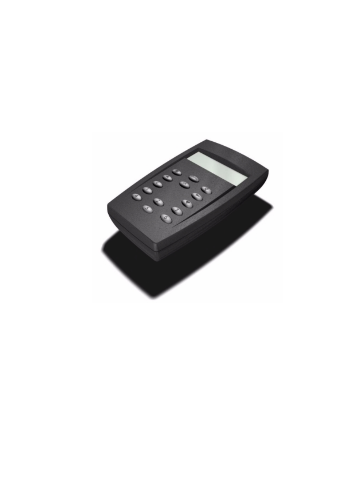
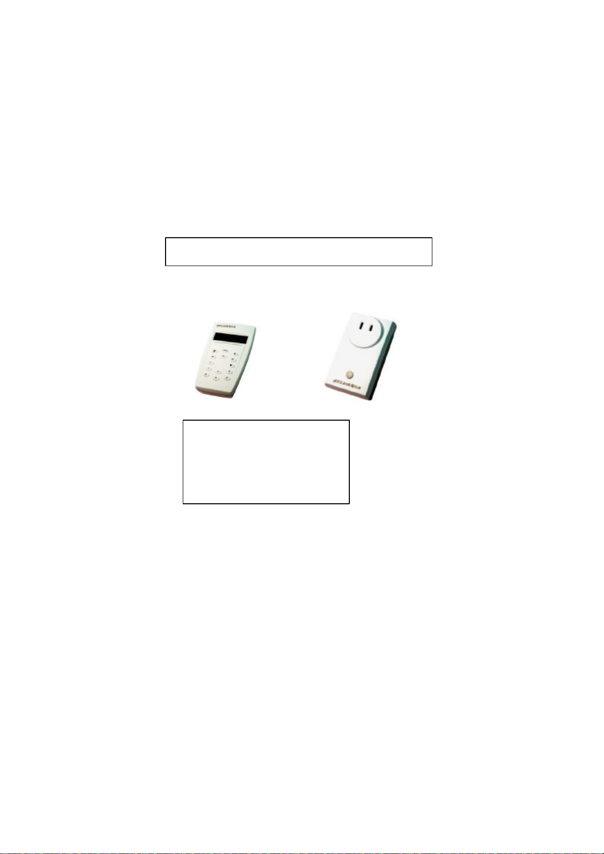
2 SYLVANIA Z-Wave Products
Remote Control with LCD
Outlet Adaptor Dimmer
About the design:
The unique product design was
developed by award winning designer
Steve McGugan.
He was the lead designer with
renowned Danish company Bang &
Olufsen before starting his own design
house.
SYLVANIA Z-Wave Lighting and Appliance Control System Manual
Page 12
11
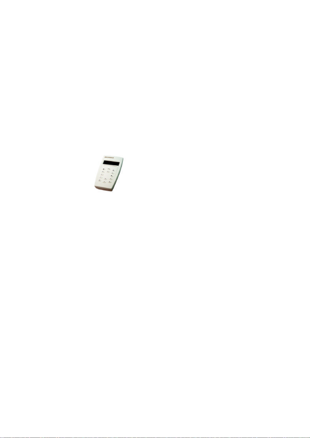
2.1 SYLVANIA Z-Wave Remote Control with display
Listed below is the feature set of the
configured differently, and the same
2.1.1 Introduction to the SYLVANIA Z-Wave Remote Control
Remote Control:
• Direct control of up to 64 Outlet
Adaptors.
• 64 groups with up to 64 Outlet
Adaptors in each. Every group can
be configured differently, and the
same Outlet Adaptor can be part of
one or more different groups.
• 32 scenes with up to 64 nodes in
each. Every Scene can be
Outlet Adaptor can be part of one or
more different groups.
• 8 timers. Each timer can be used to
control any one of the existing
groups.
• Burglar Deterrent mode that
randomly turns on/off individual
switches in the network.
• US language and time in 12H
AM/PM format
Requirements:
• Two AA batteries
• Only for indoor use
SYLVANIA Z-Wave Lighting and Appliance Control System Manual
Page 13

12
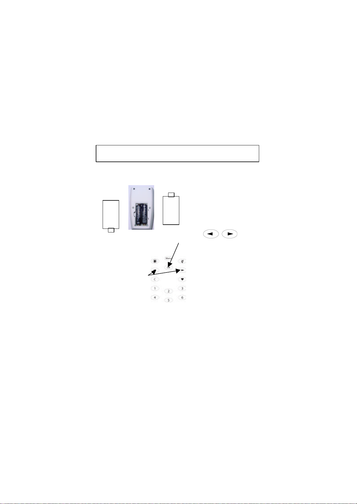
2.1.2 Button Layout
• "Menu" - Activates the menu interface
• "OK" - Accept choices
• "Light bulb on" - All ON
• "Light bulb off" - All OFF
• "Left arrow" - Navigation, left
• "Right arrow" - Navigation, right
• "C" - (Clear) steps back and cancels
actions.
• "Heart" - Scene prefix button
• "1" to "6" - Speed buttons. Grants
quick access to Groups and Scenes
SYLVANIA Z-Wave Lighting and Appliance Control System Manual
Page 14
13
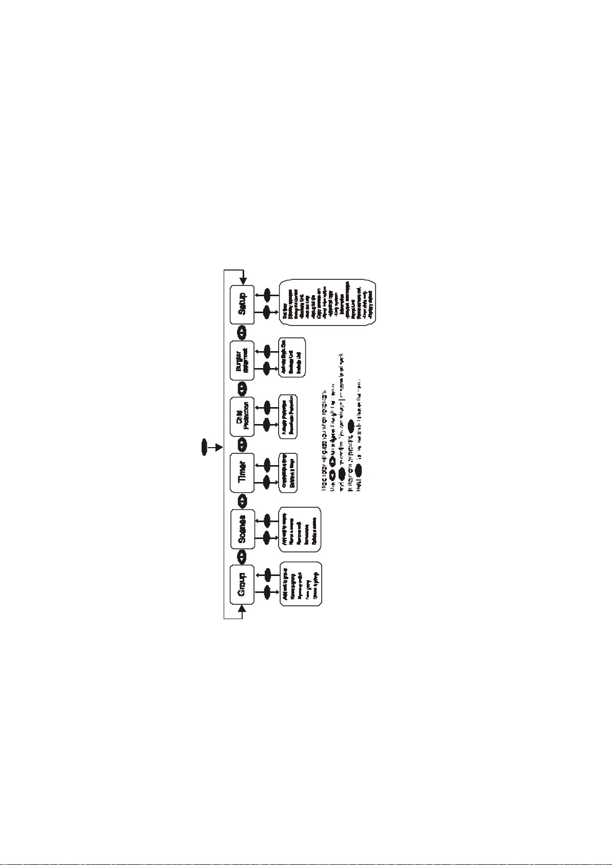
2.1.3 Menu Structure
Menu
Menu for the SYLVANIA Z-Wave Lighting and Appliance Control System
MENU
Press the button
OK C OK C OK C OK C OK C
C
OK
C
C
OK
SYLVANIA Z-Wave Lighting and Appliance Control System Manual
Page 15
14
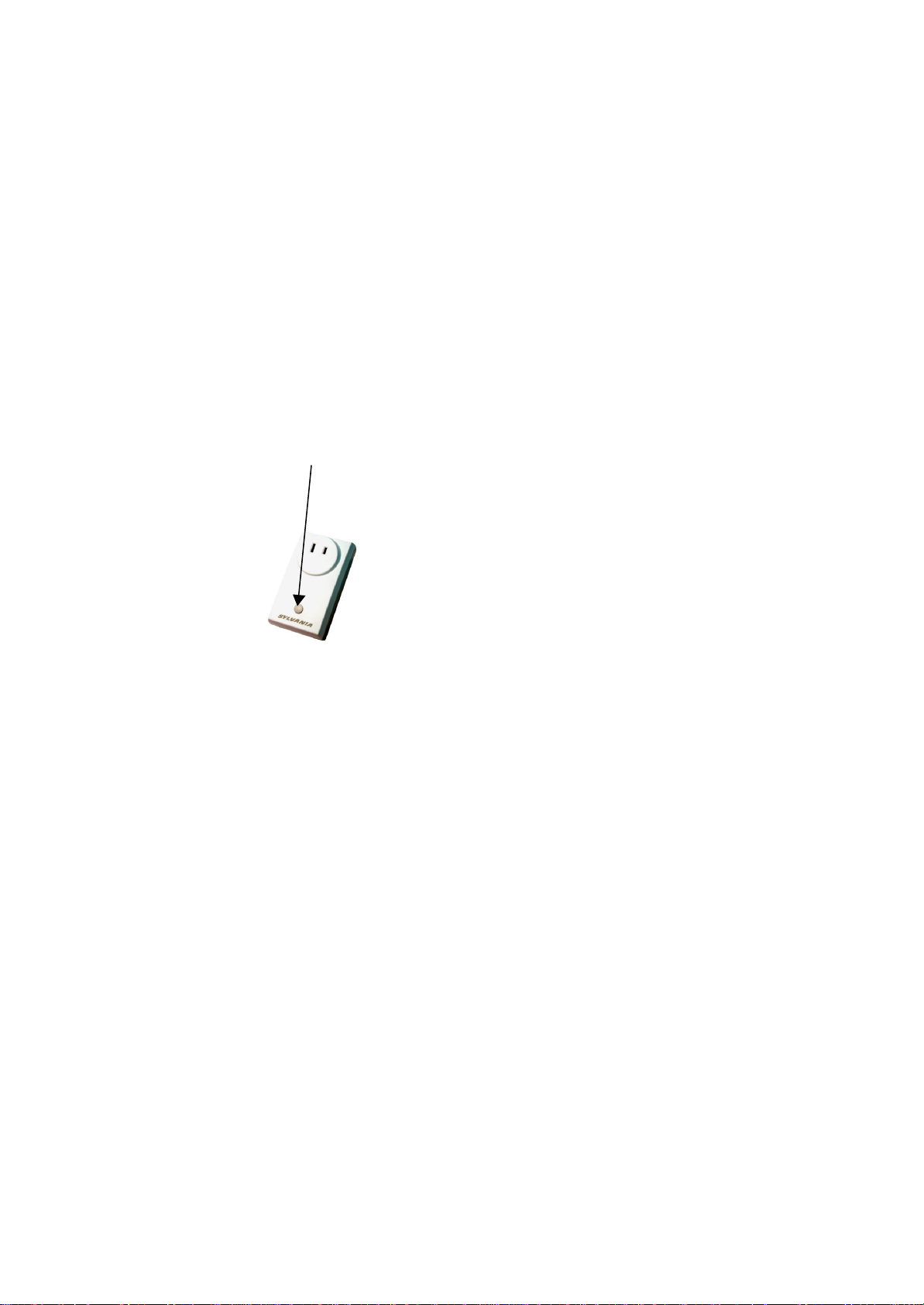
Listed below is the feature set of the Outlet
Plugs directly into the power outlet
Direct control via Outlet Adaptor
button. Short press for on and off.
Controls one or more lamps either
directly on the Outlet Adaptor button
Automatic repeater function to
tension
to low energy light bulbs, fluorescent
2.2 SYLVANIA Z-Wave Outlet Adaptor Dimmer
Introduction to the SYLVANIA Z-Wave Outlet Adaptor Dimmer
Outlet Adaptor button
Adaptor Dimmer:
•
in the wall
•
Keep pressing to dim
•
or wirelessly via the remote control
•
ensure full home coverage
Requirements:
• Maximum load 300 Watt
• Can only be connected to
incandescent lamps and lowhalogen lamps with mechanic iron
core transformers. Do not connect
lights, and low-tension halogen
lamps with electronic transformers.
• Voltage: 115V, 60Hz .
• Only for indoor use.
Warning: Only dim lamps – do not use
the Outlet Adaptor Dimmer for
electrical appliances like TV’s,
toasters, coffee makers etc. Only use
the Outlet Adaptor High Power for
electrical appliances.
SYLVANIA Z-Wave Lighting and Appliance Control System Manual
Page 16

15
2.3 Introduction to the SY LVANIA Z-Wave Outlet Adaptor
Listed below is the feature set of the
High Power(Availlable June 2003)
Outlet Adaptor button
Outlet Adaptor High Power:
• Plugs directly into the power outlet
in the wall
• Direct control via Outlet Adaptor
button. Short press for on and off
• Controls one or more electrical
appliances either directly on the
Outlet Adaptor button or wirelessly
via the remote control
• Automatic repeater function to
ensure full home coverage
Requirements:
• Maximum load 1800 Watt
• Voltage: 115V, 60Hz
• Only for indoor use
SYLVANIA Z-Wave Lighting and Appliance Control System Manual
Page 17
16
First insert 2 AA batteries in
Press the OK button to save
+
Navigation
3 How to get started - It’s incredibly easy!
3.1 Preparing the Remote Control
+
OK button
buttons
the Remote Control as
shown. You will now be
asked to set the clock (in
the display). Use the
Navigation buttons
clock and the OK button to
go from hours to minutes.
the time settings. The
Remote Control is now
ready for use.
to set the
Note: Also see section 5.1 for complete” Clock ” Set up.
SYLVANIA Z-Wave Lighting and Appliance Control System Manual
Page 18

17
1.
3.
3.2 Assigning the Outlet Adaptor to the Remote Control
Speed button 1
.
Outlet Adaptor button
SYLVANIA Z-Wave Lighting and Appliance Control System Manual
Plug the SYLVANIA Z-Wave
Outlet Adaptor (Dimmer/High
Power) directly into the power
outlet.
2. Press and hold Speed button 1
on the Remote Control.
While holding Speed button 1 on
the Remote Control, press and
release the Adapter Button until
the display says, “Unit included”.
4. Now plug the lamp cord into the
Outlet Adaptor Dimmer or
electrical appliance cord into the
Outlet Adapter High Power.
Use the same procedure to include
additional SYLVANIA Z-Wave Outlet
Adaptors.
You can now remote control the lamp or
electrical appliance. Press Speed button
1 once (short press) to turn the lamp or
electrical appliance on / off.
To dim a lamp connected to an Outlet
Adaptor Dimmer keep pressing Speed
button 1. Release and press the Speed
button to change dim direction.
Warning: Only dim lamps – do not use
the Outlet Adaptor Dimmer for
electrical appliances like TV’s,
toasters, coffee makers etc. Only use
the Outlet Adaptor High Power for
electrical appliances.
Page 19

18
4 How to use the features of the SYLVANIA Z-
Wave Lighting and Appliance Control
System
4.1 Groups/Scenes
The “Group” function allows you to organize and activate several, many, or all
lights, with the push of a button. No more wandering from lamp to lamp when
you come home, or when you’re on your way out.
When assigning an Outlet Adaptor to the Remote Control you create a group.
You can create up to 64 groups and each group can include 1-64 Outlet
Adaptors.
An Outlet Adaptor must to be assigned to a group before it can be included in a
scene. You can create up to 32 scenes and each scene can include 1-64 Outlet
Adaptor.
The layout and behaviour of the "groups" and "scenes" menu are very similar.
Where they are identical groups are used as an example.
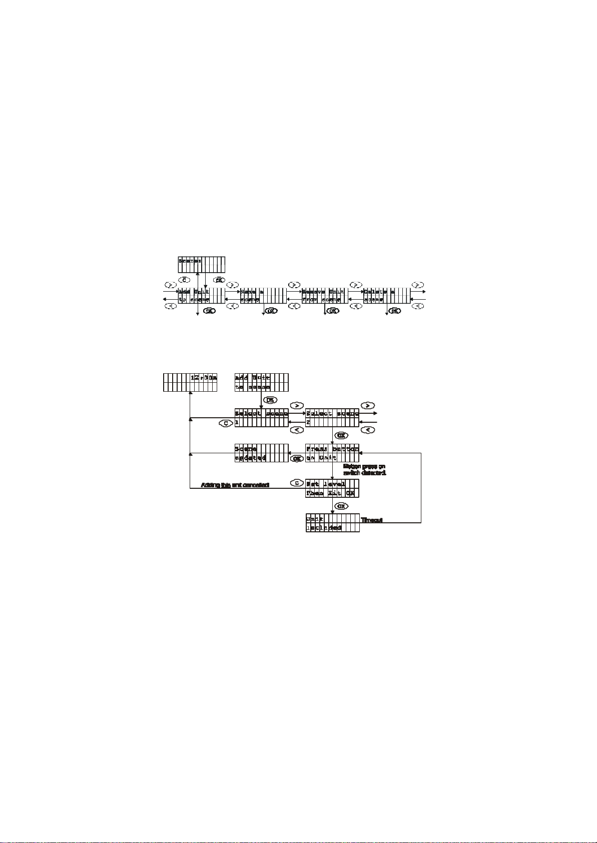
4.1.1 Add Outlet Adaptor to a group / How to create a group
SYLVANIA Z-Wave Lighting and Appliance Control System Manual
Page 20

19
Adding a switch to a group using the menu is done this way:
Alternatively if the group has been named, the name shows up instead of
You can create up to 64 groups and assign up to 64 nodes to each group:
1. Press the Menu Button. Press the OK button to access “Groups”.
2. Go to “Add Unit” using the Navigation buttons and Press OK.
3. Select a group number 1- 64 using the Navigation buttons and press
OK.
4. Now press and release the Outlet Adaptor button until the display says
“Switch Included”.
5. To add more Outlet Adaptors repeat step 4. Press OK when all Outlet
Adaptors you want to include in the group are inclu ded.
6. You have now created a group-
7. Now plug the lamp cord into the Outlet Adaptor Dimmer or electrical
appliance cord into the Outlet Adapter High Power.
the number.
SYLVANIA Z-Wave Lighting and Appliance Control System Manual
Page 21

20
4.1.2 Controlling groups
Groups are controlled by either pressing the buttons 1 through 6 or using the
Navigations buttons (marked with left or right arrows) to select the group that is
to be controlled.
4.1.2.1 Using speed buttons
The buttons marked 1 through 6 are used for speed access to the first 6 groups
or scenes.
A quick press of the number key will toggle the selected group on or off. The
display will display the following message:
Alternatively if the group is named, the name will be displayed (to easily name a
group see section 4.1.8):
The text is displayed for a few seconds or until transmission is completed.
If no group has been assigned to the selected number key the following
message will be shown for a few seconds:
B utto n not
p rogr ammed
If for some reason the transmission fails, the following message will be shown
until the user press es a key:
Group
failed!
Holding down a number key will start dimming of the selected group. Note that
once an Outlet Adaptor is at max or minimum dim level the button should be
released and held down again in order to change dim direction.
SYLVANIA Z-Wave Lighting and Appliance Control System Manual
Page 22

21
4.1.2.2 Using Navigation buttons
Another way to access groups is to use the left or right arrow buttons from the
operation state. This is the only way to control the groups from 7 to 64. Also note
that only the existing groups that show up when the user toggles through the list.
If a group is named, the name will be shown instead of the number.
A quick press of the “OK” button will unit a group on or off. Holding down the
“OK” button will dim the group. Release and hold down the “OK” button to
change the dim direction.
It looks like this:
Press and hold "OK"
SYLVANIA Z-Wave Lighting and Appliance Control System Manual
Page 23

22
1. First make sure that the Outlet Adaptor
You can also dim the lamp by pressing
Adaptor that is not part of the group your are
Press and hold Speed
4.1.2.3 Dim a group of Lamps connect to Outlet Adaptor
Dimmers
Dimmers are assigned to the Remote
button 1 to dim the lamp
connected to Speed button 1
Outlet Adaptor button
Control. Refer to previous page “Add
Outlet Adaptor to a group”.
2. To dim groups 1-6, press and hold the
respective Speed button unt il you
reach the dim level you desire. Once
an Outlet Adaptor Dimmer is at max or
minimum dim level the button should
be released and held down again in
order to change dim direction.
3.
and holding the Outlet Adaptor button
on the Outlet Adaptor Dimmer.
The next time you turn on the group of
lamps connected to the group you dimmed,
the Outlet Adaptor Dimmer will remember
the last dim level setting.
Warning: Only dim lamps – do not use
the Outlet Adaptor Dimmer for electrical
appliances like TV’s, toasters, coffee
makers etc. Only use the Outlet Adaptor
High Power for electrical appliances.
Note: While dimming the Remote Control
will be open for assigning new Outlet
Adaptors to the group you are dimming.
Therefore be aware that if someone presses
the Outlet Adaptor button on an Outlet
dimming you may accidentally assign this
Outlet Adaptor to the group. If this happens
please refer to the section “Remove Outlet
Adaptor from group/scene” how to remove
the Outlet Adaptor from the group.
SYLVANIA Z-Wave Lighting and Appliance Control System Manual
Page 24
23
4.1.3 Program a scene using the Outlet Adaptor Dimmers
1. Press the Menu button and scroll to the “Scenes” menu using the
Scenes allow you to preset different light levels, then, with the push of a button
select dinner scene, watch TV scene, evening scene, or whatever you choose.
4.1.4 Add Outlet Adaptor Dimmer to scene
Adding an Outlet Adaptor Dimmer to a scene using the menu is done this way:
Navigation buttons. Press the OK button to access the “Scene
menu”.
2. Go to “Add Switch to scene” using the Navigation buttons and press
OK to access the “Add Switch” action.
3. Select a scene number (e.g. 1,2,3 …) where you want to assign to
the scene. Press OK.
SYLVANIA Z-Wave Lighting and Appliance Control System Manual
Page 25

24
4. Now press and release the button on the Outlet Adaptor Dimmer that
When “Set level then hit OK” is shown in the display set the light level to
tinue to the next Outlet Adaptor Dimmer to be included in the scene
you want to include in the scene.
5.
the desired level using the Remote Control or by pressing the Outlet
Adaptor button directly and press OK on the Remote Control to store
the light level.
6. Con
7. When you have assigned all Outlet Adaptor Dimmers to be included in
8. Press the OK button to create the scene.
You have now programmed a scene. You can create up to 30 scenes. Note
that scenes can include switched off Outlet Adaptor Dimmers.
Note: Hitting” c” will not units that have been stored in the selected scene. A
unit is stored when “ unit included” is shown in the display.
and repeat step 4 and 5.
the scene press OK to save.
4.1.5 Controlling scenes
To re -call the scenes 1-6 first press the “Scene prefix button” . The
Remote Control will indicate that it
Select scene
is in scene selecting mode by showing
Then press the Speed button where you created your lighting scene. For scenes
7-32 press the Scene prefix button and use the Navigation buttons to select the
desired scene. Press the OK button to activate the scene. Note from the scene
mode you can only activate/turn on a scene. To turn off a selected scene you
must turn off the individual lights or groups of lights as you normally would from
the group mode. (See section 4.1.1. for help to create a group.)
SYLVANIA Z-Wave Lighting and Appliance Control System Manual
in the display.
Page 26

25
1. Enter the Group Menu
sure you want to remove an
button on the Outlet Adaptor
Clear cancels the current
4.1.6 Remove Outlet Adaptor from group/scene
You can remove an Outlet Adaptor Dimmer or High Power from a group/scene
by doing the following:
selection.
Arrows only work if more than
one group/scene exists.
2. Go to “Remove switch from
group” using the Navigation
buttons and press OK
3. Select the group
(number/name) from which
you want to remove the
Outlet Adaptor Dimmer or
High Power. Press OK.
4. Press OK again if you are
Outlet Adaptor Dimmer or
High Power from the group.
5. Press the Outlet Adaptor
Dimmer or High Power you
want to remove.
6. You have now removed the
Outlet Adaptor Dimmer or
High Power from the group
To remove an Outlet Adaptor Dimmer
from a scene enter the scene menu
and use same procedure as described
above.
Note: If you wish to move an Outlet
Adaptor Dimmer or High Power to a
new location you should reset the
Outlet Adaptor flowing the instructions
in section 5.5.1. and assign the Outlet
Adaptor Dimmer or High Power to the
Remote Control in the new location.
SYLVANIA Z-Wave Lighting and Appliance Control System Manual
Page 27

26
4.1.7 Delete group/scene
1. Enter the group menu
(number/name) you want
e “scene
To delete a group/scene follow these five steps:
If no active groups/scene exits the following occurs.
2. Go to “Delete a group”
using the Navigation
buttons and press OK
3. Select the group
to delete. Press OK
4. Press OK again if you
are sure you want to
delete the group.
5. The group is now deleted
To delete a “scene” enter th
menu” and follow the same
procedure as described above.
D el e te d
a
G ro u p
N O A
G ro u p
SYLVANIA Z-Wave Lighting and Appliance Control System Manual
t e
c i
s
v
Page 28

27
4.1.8 Name a group/scene
Character set
Assigning names makes it easier to keep track of various groups and scenes.
Name a Group
1. To name a group enter the “Group menu”
2. Go to “Name group” using the Navigation buttons. Press OK to accept
the “Name group” action
3. Use the Navigation buttons to choose which group you wish to name,
(e.g. Group 1, 2, 3 etc.). Pres s OK.
N a me
a gr o u p
OK
G r o u p 1:
9
>
Gr o u p 1:
<
_
No new group
name stored
X X : X X A
>
S e le c t g ro u p1S e l ec t g r ou p
<
>
<
Menu
G r ou p 1 :
A
G r ou p 1 :
A
_
OK
OKC
OK
X X :X X A
>
2
<
>
G r o up 1 :
B
<
Group name
stored: A
_
OK
X X : XX A
>
<
The character
under the blinking
cursor is not
stored when OK is
held down
Group name
cleared
OK
The
indicates that the OK button
should be held for 2 seconds.
The characters available for naming is:
'A','B','C','D',..,'Z','0','1','2',..,'9',' '
SYLVANIA Z-Wave Lighting and Appliance Control System Manual
Page 29

28
1. Type the name using the Navigation buttons to scroll through the alphabet
To name a “Scene” follow the same procedure as for naming a “Group”, but use
and press OK to select the wanted letter. You can choose letters from “A”
to “Z” and numbers from “0” to “9”
• To clear a letter press Cancel
• To edit a name use Cancel to clear the name then
enter the new name
• For space; scroll to the end of the alphabet
2. When you finished spelling the name, press the OK button for a few
seconds to store the name. The character under the cursor is not stored
when OK is held down
3. You have now named Speed button 1.
Try to press the Speed button 1 and notice the new name on the display.
Name a Scene:
the “Scene menu” instead of the “Group menu”.
SYLVANIA Z-Wave Lighting and Appliance Control System Manual
Page 30

29
4.2 All ON and All OFF
All ON/OFF turns all connected lights on or off with the touch of one button in
case you come home late or hear noises in the middle of the night.
All ON
All OFF
1. Press the All ON button
to turn all the connected Outlet
Adaptor Dimmers and/or Outlet
Adaptors High Power ON.
2. Press the All OFF button
to turn all the connected Outlet
Adaptor Dimmers and/or Outlet
Adaptors High Power OFF.
Both commands will be confirmed in the
display. Note that you can configure the
ALL ON / ALL OFF functionality to
exclude one or more Outlet Adaptor
Dimmers and/or Outlet Adaptors High
Power. See the “Set-Up” section for this
feature.
T
u nr
Pressing the "All ON" button will show this display
OFF" will result in
This display will be shown for the duration of the acknowledgement, which for larger
set-ups can be a while.
If the transmission fails either
be shown until the Remote Control powers down or you press a button.
T
unr
All
ing O
Un
itffs
A l l On
f a il ed!
A ll
or
g O n
i n
U n
i t s
A l l O ff
f a ile d!
and "All
will
SYLVANIA Z-Wave Lighting and Appliance Control System Manual
Page 31

30
4.3 Timer
By applying a timer to a specific group you can preset the time when a lamp or
electrical appliance (or group of lamps and appliances) should turn on and off.
You might even want to ensure that the kids TV turns off at a certain time …
T i me r
OKC
C r ea t e / Ed i t
a ti m e r
OKC OKC
>
D e l et e a
t i m er
<
4.3.1 Create/Edit a timer
There are eight timers available that can be assigned to one of the existing
groups as chosen by the user.
SYLVANIA Z-Wave Lighting and Appliance Control System Manual
Page 32

31
Creating a timer requires the clock has been set on the Remote Control (See
Note: If an existing timer is selected that timer will be edited. The time
“Set-Up commands”).
1. Press the Menu button.
2. Go to “Timer” using the Navigation buttons and press OK to access the
sub-menu.
3. Go to “Create a timer” using the Navigation buttons and press OK.
4. Select a Timer number (1-8) using the Navigati on buttons and press
OK.
5. Set the start time of the Timer. The gray block indicates a blinking
cursor. Use the Navigation buttons to scroll through hours and minutes.
Press OK to confirm.
6. Set the end time using the Navigation buttons. Press OK to confirm.
7. Now select if the Timer should be recurring (every day) or just once.
Press OK.
8. Select the group (number/name) you wish to install the timer.
9. The timer has been installed and the text “Timer created” is shown in
the display.
Now the Remote Control will tu rn the group ON/OFF at the times you’ve just
preset.
indicated when selecting a timer is the start time of that timer.
Pressing the clear button will cancel the editing and leave the timer as it was.
If a group is named the group name will be show.
SYLVANIA Z-Wave Lighting and Appliance Control System Manual
Page 33
32
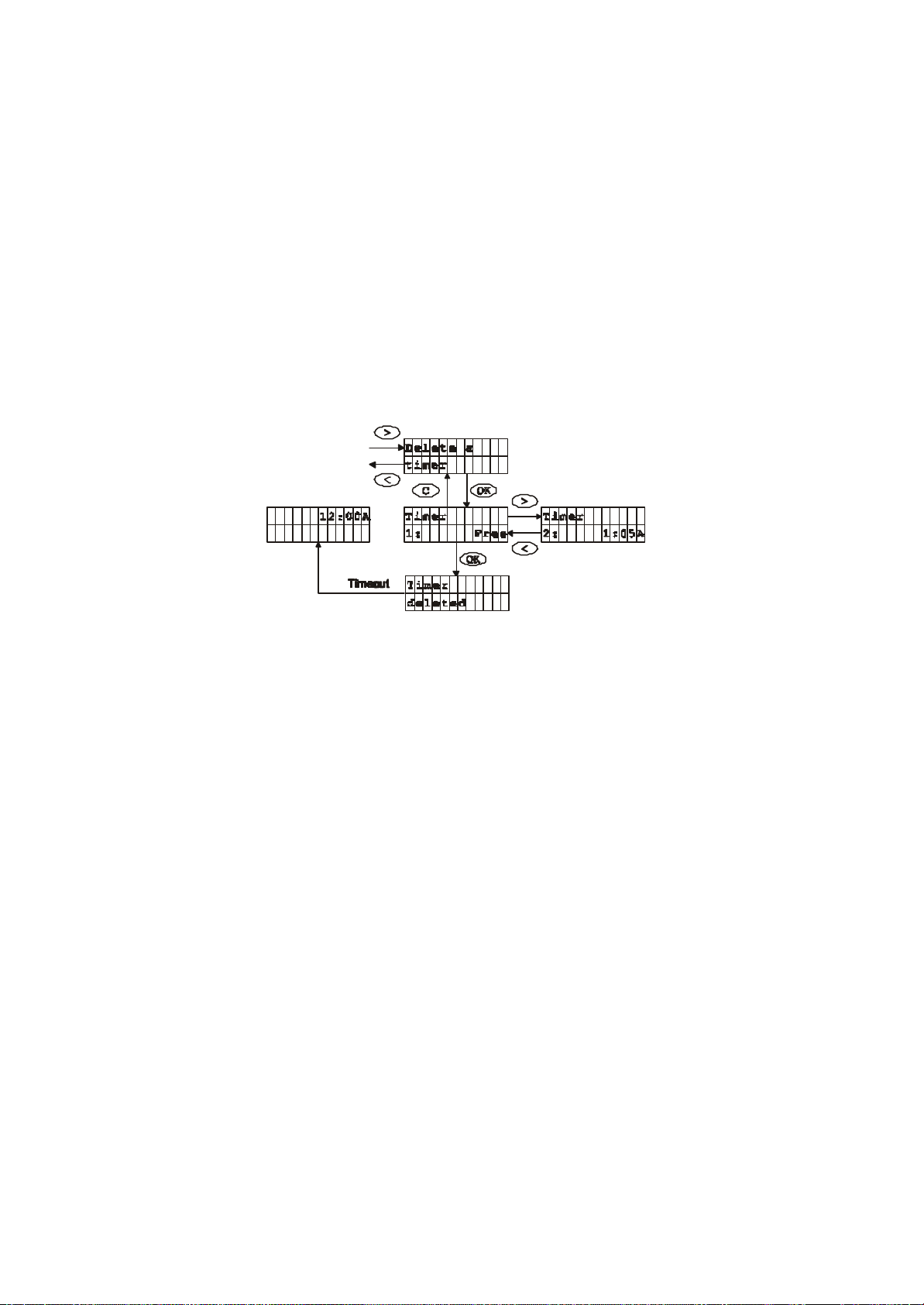
4.3.2 Delete timer
1. Enter the Timer Menu
When a timer is no longer needed it can be deleted using “Delete a timer” menu.
2. Go to “Delete a timer” and press OK
3. Select the Timer you wish to delete and press OK
4. The Timer is deleted and the text “Timer deleted” is
shown in the display
SYLVANIA Z-Wave Lighting and Appliance Control System Manual
Page 34

33
4.4 Child Protection
Activate Child protection
tons. Press OK
Power you wish to activate the Child Protection
You can only turn the Outlet Adaptor Dimmer or High Power on or off
Child Protection is a unit feature that protects against unintended use of a unit for
this feature to work the unit must support it.
4.4.1 Activate Chi ld protection
1. Press the menu-button.
2. Go to “Child Protection” using the Navigation but
to access the sub-menus.
3. Scroll to “Activate protection” using the Navigation buttons.
Press OK.
4. Press OK again if you are sure you want to activate Child
protection.
5. Now press the Outlet Adaptor button on the Outlet Adaptor
Dimmer or High
on.
6. You have now activated the Child Protection and the text
“Switch lock activated” will be shown in the display.
by pressing the Outlet Adaptor button quickly three times in a row.
SYLVANIA Z-Wave Lighting and Appliance Control System Manual
Page 35

34
If a switch button is pressed you will get either:
4.4.2 Deactivate Child protection
U i t l o c k
n
a c t i v a t e d
U it lock
n
deactivated
or
depending on which of the two options you
selected.
1. Press the menu-button.
2. Go to “Child Protection” using the Navigation buttons. Press OK to
access the sub-menus.
3. Scroll to “Deactivate protection” using the Navigation buttons. Press
OK.
4. Press OK again i f you are sure you want to deactivate the Child
protection.
5. Now press the Outlet Adaptor button on the Outlet Adaptor on witch
you want to deactivate the Child Protection on.
6. You have now deactivated the Child Protection and the text “Unit
lock deactivated” will be shown in the display.
SYLVANIA Z-Wave Lighting and Appliance Control System Manual
Page 36

35
4.5 Burglar Deterrent
By activating the Burglar Deterrent the Remote Control will randomly turn lamps
and electrical appliances connected to an Z-Wave enabled Outlet Adaptor
Dimmer and/or High Power on and off during in the time interval set by the user
in the customize time menu and hereby simulate activity in the house. By default
no Outlet Adaptors are included in the “Burglar Deterrent mode” therefore the
first step is to include the Outlet Adaptors that should be randomly
activated/deactivated by the Burglar Deterrent.
Please Note before you begin using the burglar deterrent function:
1. When the Burglar Deterrent period ends or is deactivated by the user, the
2. Because of the randomness involved, the actual start time when the Burglar
3. After burglar deterrent has activated the first Unit it will make sure that at
4. If only one Unit is included in burglar deterrent this Unit will be turned on
5. When the end time is reached it will take form 0 to 59 minutes before it turns
6. Burglar deterrent information is only stored in the remode.
SYLVANIA Z-Wave Lighting and Appliance Control System Manual
Remote Control will turn OFF all the Outlet Adaptors it currently has marked
as activated. This may include Outlet Adaptors that were already on before
the Burglar Deterrent was started.
Deterrent activates the first Outlet Adaptor will vary from the start time with
+/-15 minutes.
least one Unit is on during the burglar deterrent period.
when burglar deterrent activates the first time and not be turned off until
burglar deterrent ends. This is a result of 3.
off the nodes it activated.
Bu rg la r
de te rr an t
OKC
Ac ti va te
Br gl r. D et .
>
E xc lu de
U ni t
<
OK OKOK
>
I n cl ud e
U n it
<
>
<
Page 37

36
4.5.1 Activate burglar deterrent
Activating burglar deterrent will take the user through time period customisation
and put the remote into a special mode where it will stay unit burglar deterrent is
cancelled.
As default no units are included in burglar deterrent. If that is the case this
message will be shown when the user tries to activate burglar deterrent:
No A c t iv e
Un i t s
SYLVANIA Z-Wave Lighting and Appliance Control System Manual
Page 38

37
4.5.2 Exclude Unit
Exclude Outlet Adaptor
An included Unit can be excluded once again using this menu. Note that by
default no Units are included in the burglar deterrent mode.
Follow this procedure to exclude an Outlet Adaptor from the Burglar
Deterrent.
1. Enter the “Burglar Deterrent menu”
2. Go to “Exclude Unit” using the Navigation buttons and press
OK
3. Press OK again if you are sure you want to exclude the Outlet
Adaptor
4. Now press and release the Outlet Adaptor button on the Outlet
Adaptor you wish to exclude from the Burglar Deterrent
5. You have now excluded the Outlet Adaptor from the Burglar
Deterrent and the text “Switch Unit” is shown in the display
SYLVANIA Z-Wave Lighting and Appliance Control System Manual
Page 39

38
4.5.3 Include Unit
Add Outlet Adaptor to Burglar Deterrent
When first activating burglar deterrent the Units that the user wants to use should
be included using this menu. In addition an excluded Unit can be included once
again using this menu.
1. Enter the “Burglar Deterrent menu”
2. Go to “Include switch” using the Navigation buttons. Press
OK
3. Press OK again if you are sure you want to include the
Outlet Ada ptor in the Burglar Deterrent
4. Now press and release the Outlet Adaptor button on the
Outlet Adaptor (Dimmer or High Power) you wish to include
in the Burglar Deterrent.
5. You have now included the Outlet Adaptor in the Burglar
Deterrent.
SYLVANIA Z-Wave Lighting and Appliance Control System Manual
Page 40

39
Set clock
5 Set-up Commands
The set-up menu is used to access system functions. The layout is as follows:
5.1 Set Clock
1. Press the Menu button.
2. Go to “Setup” using the Navigation buttons and press OK to access
the submenu.
3. Go to “Set time” using the Navigation buttons and press OK.
4. Use the Navigation buttons to scroll through hours and minutes and
press OK to confirm.
5. You have now set the time
SYLVANIA Z-Wave Lighting and Appliance Control System Manual
Page 41

40
5.2 Adjust the display contrast
“C ” cancels the contrast adjustment and returns to idle. Default
Adjust the display contrast
1. Press the Menu button
2. Go to “Display contrast” using the Navigation button and
press OK to access the submenu.
3. Use the Navigation buttons to adjust the contrast in the
display. Press the right Navigation button to increase the
contrast in the display. Press the left Navigation button to
reduce the contrast.
4. Press OK when you reach the contrast level you desire.
contrast is 50%, which is restored whenever the batteries have
been removed.
SYLVANIA Z-Wave Lighting and Appliance Control System Manual
Page 42

41
5.3 Setup All ON/OFF
5.3.1 Exclude or Include an Outlet Adaptor in All
You have now excluded or included the Outlet Adaptor from the
Using this menu it is possible to customize the way All ON/OFF works. Outlet
Adaptors can be included or excluded from all ON/OFF commands (Outlet
Adaptors are by default included the first time they are added to the network)
ON/All OFF functionality
1. Press the Menu button
2. Go to “Set-up All ON/OFF” using the Navigation button and
press OK to access the submenu.
3. Using the Navigation button you can chose to “Exclude Unit” or
“Include Unit”.
4. Press the OK button to “exclude” or “include” an Outlet
Adaptor.
5. Now press and release the Outlet Adaptor button on the Outlet
Adaptor you wish to exclude or include in the All ON/ All OFF
function. The display will confirm with “Excl. from All ON/OFF”
or “Included in All ON/OFF”.
6.
All ON/OFF function.
SYLVANIA Z-Wave Lighting and Appliance Control System Manual
Page 43

42
5.3.2 Activate/deactivate the All ON function
1. Press the Menu button
2. Go to “Setup All ON/All OFF” using the Navigation button and press
OK to access the submenu.
3. Go to “Setup All ON” and press OK
4. Using the Navigation button you can chose to “Activate All ON” or
“Deactivate All ON”
5. Press OK to activate or deactivate the All ON function
6. You have now activated or deactivated the All ON function and the
text “All ON Activated” or “All ON Deactivated” is shown in the
display.
5.4 Add new remote Control to system.
You can have more then one Remote Control in your home for the same-e.g.
one in each of the rooms you use the most.
There are two options. If you want an exact copy of the master Remote Control
including groups, scenes, names, and settings, ”Identical copy” should be
selected. If you want to create groups, scenes and names from scratch “ Only
system information” should be selected.
The one Remote Control you already have programmed will be the “Master
Remote Control” and the one you wish to transfer the information to will be the
“Slave Remote Control”. All “SLAVE” remotes can be identified by an
“underscore line ’ shown in the bottom left hand corner of the LCD screen.
C op y
r em o t e c tr l .
S en d
I nf o r ma t io n
OKC
>
R e ce i ve
I n fo r ma t io n
<
OKC OK
SYLVANIA Z-Wave Lighting and Appliance Control System Manual
Page 44

43
A replication of a remote is done by :
1. Select “ Receive information” on the controller which should receive the
information (i.e. the Secondary controller)
2. select “Send information” and either “identical copy” or “Only system
information” on the remote that is to send the information (i.e. the Primary
controller).
3. Wait until transmission is completed and both the controllers’ ends.
4. If a transmission error occurs. Please repeat from 1.
Considerations:
1. It is important to note that all information on the receiving remote will be
deleted before any information is received.
2. Burglar deterrent and timer information is not copied to the slave remote.
3. Slave remotes can not be used to add newly acquired or reset Units to the
network.
4. If nodes are moved physically it should be done as mentioned in 5.5.1 and
the replication should be repeated.
5. New nodes added to the network is not automatically known by the slave
remotes, but has to be transferred to it by repeating replication, or by
adding the newly created node to a group or scene on the slave
remote(before it is known by it ).
SYLVANIA Z-Wave Lighting and Appliance Control System Manual
Page 45

44
Please note the following before replicating the master Remote Control.
up” menu on the secondary (new) Remote Control and go
5.4.1 Send information
1. All existing data on the receiving or “Slave Remote Control” will be
overwritten by the new data.
2. Burglar Deterrent and Timer information is not copied to the Slave Remote
Control.
3. Slave Remote Controls can not be used to add newly acquired or reset
Outlet Adaptors to the network
4. If a Slave Remote Control is added as one of the first 64 Outlet Adaptors. It
will take up a node thus limiting the number of Outlet Adaptors that can be
controlled from the Remote Control.
How to copy the Master Remote Control to a Slave Remote Control:
1. To add a new (Slave) Remote Control to the system press the Menu button
on the (Master) Remote Control you want to copy from.
2. Go to “Set-up” using the Navigation buttons and press OK to access the
submenu.
3. Go to “Copy remote ctrl.” Using the Navigations buttons and press OK
4. Select “Send information” and press OK
5. Choose if you want to make an “Identical copy” or “Only system information”.
Press OK. Press OK again to confirm and send the information.
6. Now enter the “Setto “Copy remote ctrl.”
7. Select “Receive information” and press OK
8. Press OK again to receive the information from the primary Remote Control.
This may take up to a few minutes.
You have n ow added a new Remote Control to your Home Control System. An
underscore in the left bottom corner of the display will indicate that this is a Slave
Remote Control.
SYLVANIA Z-Wave Lighting and Appliance Control System Manual
Page 46

45
5.4.2 Receive information
SYLVANIA Z-Wave Lighting and Appliance Control System Manual
Page 47

46
5.5 Reconfiguring the system
5.5.1 Reset an Outlet Adaptor Dimmer or Outlet Adaptor High
Power
Reset the Outlet Adaptor
the Outlet Adaptor button on the Outlet Adaptor you want
In case you want to make changes or even start all over again it is easy to reset
your Lighting and Appliance Control System.
If an Outlet Adaptor is to be moved to a new position or added to a new
network, it should be reset before doing so. This is done using this menu.
1. Press the Menu button.
2. Go to “Setup” using the Navigation buttons and press OK to
access the submenu.
3. Go to “Reset Unit” using the Navigation buttons and press OK.
4. The display will now read “Press button on switch”.
5. Press
to reset.
6. The display will confirm when the Outlet Adaptor is reset.
SYLVANIA Z-Wave Lighting and Appliance Control System Manual
Page 48

47
Reset the Remote Control
are still
potentially attempt to use routes that no longer exist.
5.5.2 Reset Remote Control
The Remote Control can be reset in two different ways. User data only and
factory default:
• User data only, will only reset groups, scenes and names. All Units
known by the protocol so they can be used for routing.
• Factory default will clear the Remote Control for all information. also on a
protocol level. Thus is should be used with extreme care.
Use the following procedure to reset the Remote Control:
1. Press the Menu button.
2. Go to “Setup” using the Navigation buttons and press OK to access
Important Notice: When moving the Outlet Adaptor (Dimmer/High Power) it is
important to reset the Outlet Adaptor that is to be moved, and include it again
once it has been placed at the new location. Otherwise the routing table store d
by the Remote Control will not be updated, and the Remote Control will
the submenu.
3. Go to “Reset Remote Ctrl.” using the Navigation buttons and press
OK.
4. Select “Factory default” or “Only user data”. Press OK.
5. Now the display will ask “Are you sure?”. Press OK if you want to
reset the Remote Control.
6. The display will confirm when the Remote Control is reset.
SYLVANIA Z-Wave Lighting and Appliance Control System Manual
Page 49

48
6 Operation Mode
6.1 Operation display
1 2:0 0A
When the clock is displayed the Remote Control is in operation mode. It is from
this mode the Outlet Adaptors (Dimmer and High Power) can be controlled
through either groups or scenes.
6.2 Slave Remote Control indication
12:00A
_
When an underscore is shown in the left bottom corner the remote is a Slave
Remote Control with the limitations mentioned elsewhere.
6.3 No active group indication
If no active groups/scene exists the following occurs:
No active
groups
6.4 Scene indication
When pressing the scene prefix button (heart) from operation mode the display
will change to:
Select scene
This indicates that the next key press will be used to control a scene (if any
available).
SYLVANIA Z-Wave Lighting and Appliance Control System Manual
Page 50

49
6.5 Low battery indication
This message indicates that it is time to replace the batteries. It will
go away when the batteries have not been replaced.
12:00A
Change batt.
7 Product Support
Product support:
VTC SERVICE & MANUFACTURING CO., INC.
16988 GALE AVENUE, CITY OF INDUSTRY,CA
91745-1805 Telephone(866)342-5733 between 8:00am
and 4:30 pm Pacific standard Time.
SYLVANIA Z-Wave Lighting and Appliance Control System Manual
Page 51

50
Errors you might
encounter
You press and hold
the Speed button and
press the Outlet
Adaptor button to
include a new Outlet
Adaptor - but nothing
happens
You keep
receiving ”Group
Failed” or “Scene
failed” on the display
when you try to turn
the “lights” on or off.
The display on the
Remote Control goes
blank after some time.
8 Troubleshooting
Reasons What you do
The Remote Control
1. The Outlet Adaptor
belongs to a different
system than yours.
One of the following
reasons:
1. You are too far away
from one or several of
the Outlet Adaptor
you’re trying to control
2. One or several Outlet
Adaptors you are
trying to control are
disconnected from
power.
To save power the display
will turn off automatically
after 5-10 seconds. If
you’re in the menu the
power will turn off after 1
minute without activity.
2. Reset the Outlet
Adaptor. See Set-up
menu section 5.5.1.
1. Check the
2. Check if the
Press any button
and the power in the
display switches on
again.
distance to the
nearest Outlet
Adaptor.
power to all the
Outlet Adaptors
is turned on.
If you want to
disconnect an
Outlet Adaptor
remember to
reset it before
disconnecting to
prevent error
messages. See
Set-up menu
section 5.5.1.
SYLVANIA Z-Wave Lighting and Appliance Control System Manual
Page 52

51
A group suddenly
includes an Outlet
Adaptor that you
didn’t assign to the
Remote Control
yourself.
As you dim your group
someone else presses the
button on an Outlet
Adaptor that is not part of
the group you are
dimming (either to turn on
or off the light/appliance
directly on the Outlet
Adaptor). While dimming
the Remote Control is
open for assigning new
Outlet Adaptors why the
Outlet Adaptor is included
in the group you are
dimming.
To remove the Outlet
Adaptor from the
group please refer to
section 4.1.6
“Remove Outlet
Adaptor from
group/scene”.
Outlet Adaptor Dimmer / Outlet Adaptor High
Power
You want to turn the
Outlet Adaptor on or
off by pressing the
Outlet Adaptor
button, but nothing
happens.
The Outlet Adaptor is
probably Child Protected.
Press the Outlet
Adaptor button three
times quickly to turn
on or off the Outlet
Adaptor. To disable
the Child Protection
scroll to “Child
Protection” in the
menu and go to
“Deactivate
protection”. Press
OK and then press
the Outlet Adaptor
button on the Outlet
Adaptor you wish to
deactivate the Child
protection. The Child
Protection is now
deactivated.
SYLVANIA Z-Wave Lighting and Appliance Control System Manual
Page 53

52
SYLVANIA Z-Wave Remote Control
Power
Two AA batteries
• Wireless control of Outlet
Adaptors and Wall Switch
Switches on/off and dims
Protection and
Can create 64 groupings of
your lamps as well as 32
Can operate up to 64 Outlet
Adaptors and Wall Switch
friendly menu based
Features
Modules
•
your lamps and appliances
• Timer, Child
Burglar Deterrent
•
different scenes
•
Modules
• User-
operation
Specifications
Technical Specifications:
Signal 908.42 MHz USA
LCD Display 2 x 12 Character
Range 100 feet (line of sight between the Remote
Physical Specifications:
Dimensions 4,7”L x 2,8”W x 1,2”H
Weight Approx. 8 oz.
User Interface Button Keypad
Operating Temperature 32 – 1050F (0 – 400 C)
Environment Only for indoor use
Control and the nearest Outlet Adaptor or
Wall Switch)
SYLVANIA Z-Wave Lighting and Appliance Control System Manual
Page 54

53
SYLVANIA Z-Wave Outlet Adaptor Dimmer
• Plugs directly into the
Controls one or more
lamps either directly on
the module or wirelessly
Power) ensures full home
Features
power outlet in the wall
•
via the remote control
• Automatic repeater
function of commands
between Outlet Adaptors
(Dimmers and High
coverage
Specifications
Technical Specifications:
Power 120 VAC, 60 Hz USA
Signal 908.42 MHz USA
Maximum Load 300 W
Range 100 feet (line of sight between the
Connectability Can only be connected to
Remote Control and the nearest
Outlet Adaptor or Wall Switch)
incandescent lamps and lowtension halogen lamps with
mechanic iron core transformers.
Do not connect to low energy light
bulbs, fluorescent lights, and lowtension halogen lamps with
electronic transformers.
Physical Specifications:
Dimensions 4,7”L x 2,44”W x 1,54”H
Weight Approx. 5 oz.
Operating Temperature 32 – 1050F (0 – 400 C)
Environment Only for indoor use
SYLVANIA Z-Wave Lighting and Appliance Control System Manual
Page 55

54
SYLVANIA Z-Wave Outlet Adaptor High Power
Power
120 VAC, 60 Hz USA
• Plugs directly into the power
home coverage
Features
outlet in the wall
• Controls one or more
electrical appliance either
directly on the module or
wirelessly via the remote
control
• Automatic repeater function
of commands between
Outlet Adaptors (Dimmers
or High Power) ensures full
Specifications
Technical Specifications:
Signal 908.42 MHz USA
Maximum Load 1800 W USA
Range 100 feet (line of sight between the
Connectability Do not connect electrical
Remote Control and the nearest
Outlet Adaptor or Wall Switch)
appliances over 1800 W in USA
Physical Specifications:
Dimensions 4,7”L x 2,44”W x 1,54”H
Weight Approx. 5 oz.
Operating Temperature 32 – 1050F (0 – 400 C)
Environment Only for indoor use
SYLVANIA Z-Wave Lighting and Appliance Control System Manual
 Loading...