

Page 1

IMPORTANT SERVICE INFORMATION
Read this manual before attempting to setup or use this
instrument. It contains important infor mation regard ing safe
installation and use . Keep this manual for future re ference.
Also save the carton, packing and proof of purchase
simplify and accelerate any needed action.
MAINTENANCE (SERVICING)
THIS SYMBOL IS INTENDED TO ALERT
THE USER OF THE PRESENCE OF
IMPORTANT OPERATING AND
INSTRUCTIONS IN THE OWNER'S
MANUAL.
to
102106A-1 1
Page 2

2 102106A-1
CARTON CONTENTS
• 99152 Family Radio Service
• User-Replaceable Belt Clip
• Holder
• User’s Manual
• Warranty Card
• Accessory Order Form
• Eight “AAA” Batteries
99152
Page 3
MAINTENANCE
1. Use a damp cloth to clean the plastic cabinet. A mild
soap will help to remove grease or oil. Never use
polish, solvents, abrasives or stro ng detergents since
these can damage the finish.
2. Your FRS should be situated away from heat sources
such as radiators, heaters, stoves or any other
appliance that produces heat.
SAVE THESE INSTRUCTIONS
FCC NOTICE
Warning: Change s or modifica tions to t his unit not
expressly approved by the party responsible for compliance
could void the user authority to operate the equipment.
This device complies with Part 15 of the FCC Rules.
Opera tion is sub ject to the following two conditions: (1 ) this
device may not cause harmful interference, and (2) this
device must accept any interference received, including
interference that may cause undesired operation.
NOTE: This equipment has been tested and found to
comply with the limits for a C lass B d igita l device, p ursua nt
to Part 15 of the FCC Rules. These limits are designed to
provide reasonable protection against harmful interference
in a res ident ial inst allat ion. T his equ ipment genera tes, us es
and can radiate radio frequency energy and, if not installed
and used in accordance with the instructions, may cause
harmful interference to radio communications.
However, there is no guarantee that interference will not
102106A-1 3
Page 4

occur in a particular installation. If this equipment does
cause harmful interference to radio or television reception,
which can be determined by turning the equipment off and
on, the user is encouraged to try to correct the interference
by one or more of the following measures:
- Reorient or relocate the receiving antenna.
- Increase the separation between the equipment and
receiver.
- Connect the equipment into an outlet on a circuit
different from that to which the receiver is needed.
- Consult the dealer or an experienced radio/TV technician
for help.
The equipment complies with FCC RF radiation exposure
limits set forth for an uncontrolled environment, under 47
CFR 2.1093 paragraph (d)(2). The (Product name) has
been tested to the FCC exposure requirements (Specific
Absorption Rate).
4 102106A-1
Page 5

FRS RPODUCT DESCRIPTION
The Family Radio Service (FRS) is the newest generation in
personal two-way communications.
The 99152 is a lightweight, palm-sized two-way radio that
can be used up to about two miles with family or friends at
parks, shopping malls, sporting events, concerts, any indoor
or outdoor activity!
The 99152 is a 22-channel Family Radio Service, which
features last channel recall and battery save circuitry.
Please red the use’s manual thoroughly to get the most out
of your 99152 Family Radio Service.
NOTE: The maximum transmission range will vary
depending on terrain and environment. Range will be
greater in open fields, while the range is shorter
within/around buildings or large st ructures.
The radio operates on the Family Radio Service (FRS)
freque nc ies whe n us in g cha n ne ls 1 -14 . I t do n’t ne ed to ha ve
a FRS license .The radio operates on the General Mobile
Radio Service (GMRS) frequencies when using channels
15-22. You must have a GMRS license issued by the Federal
Communications Commission to legally use these channels.
102106A-1 5
Page 6
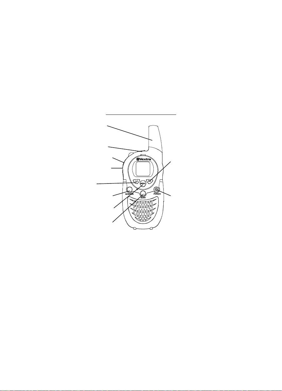
99152 CONTROLS DI AGRAM
Flexible Antenna
MIC/HAEDSET
Jack
CALL Button
TALK Button
UP
Button
MONITOR Button
MENU Button
SCAN Button
DN Button
POWER Button
6 102106A-1
Page 7

DESCRIPTIONS
Power Button – Press and hold the Power button for at least
2 seconds to turn on and off the FRS radio. The unit will
beep, the LCD panel will display information about your
radio, and the panel will be illuminated by a light for se vera l
seconds.
Battery Compartment - Houses eight “AAA” type
batteries (included).
Belt Clip - For your convenience, a belt chip is included to
secure the radio to a belt or any other convenient location.
CALL Button - Used to alert the other user or to identify
yourself.
TALK Button - Used for transmitting (making a call).
SCAN Button - Your radio can scan across it is 22 channels
for any activity. This allows you find other radios without
having to cha nge channels .
MENU Button - Used to set channel and calling ringer.
Monitor Button – Lets you listen in on a channel for weak
signals.
UP /DN Button - Allow you to control the volu me level
(The LC D dis pla ys the volu me le vel b y th e numb er o f bars
on the screen) and change channels. Press the UP button to
increase volume. Press the DN button to decrease volume.
102106A-1 7
Page 8
External Mic / Headset Jack – A jack located under the
protective rubber cover on the top of the unit, the side of the
handset is used for connecting your headset to enjoy a
hands-free communication.
INSTALLATION
Battery Installation
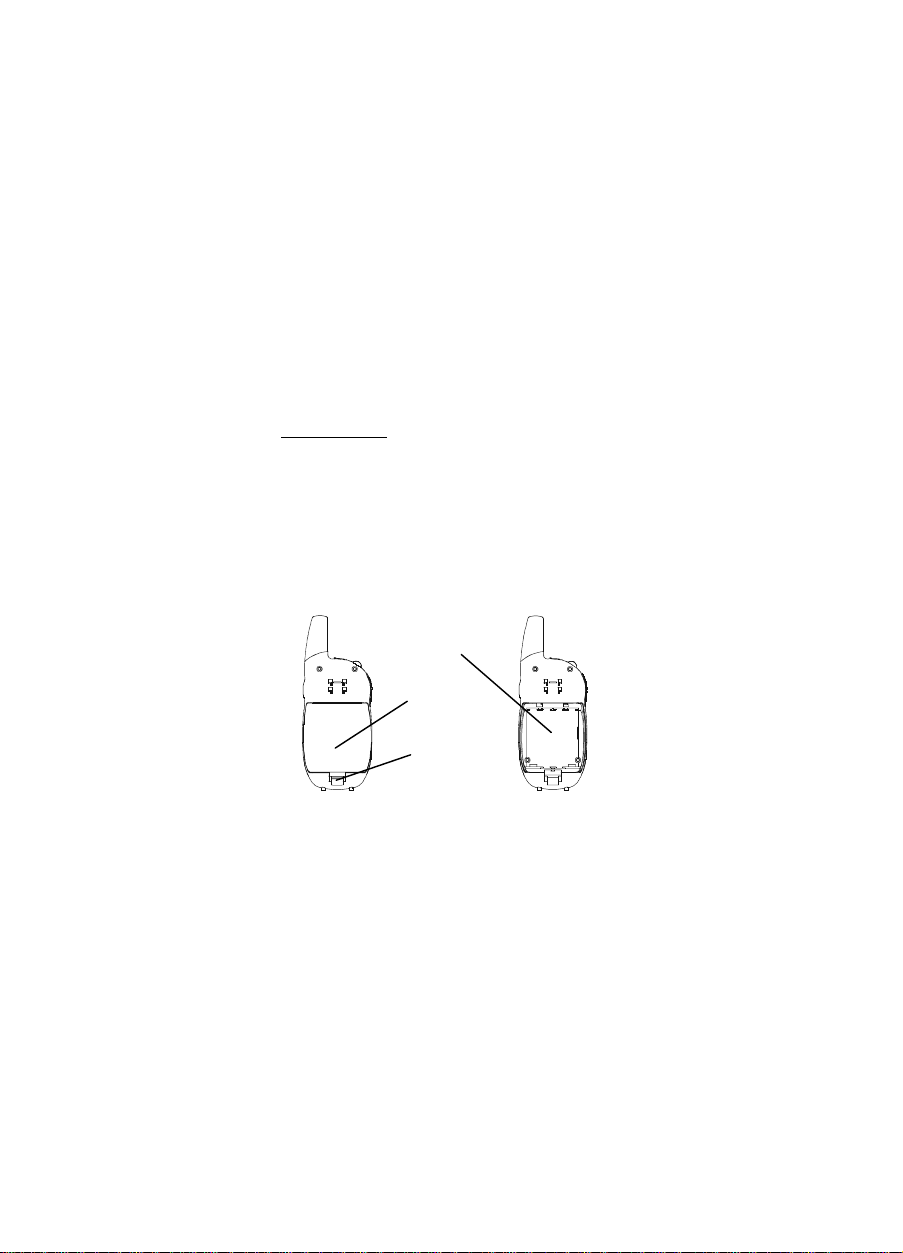
1. Release the battery cover latch located on the rear
side of the unit.
2. Lift up the battery cover from the battery
compartment.
3. Install four “AAA” type batteries (included). Please
make sure the correct polarities.
4. Reinstall the battery co ver.
5. Lock the battery cover latch into position.
Battery
Compartment
Battery
Compartment
Cover
Battery Cover
Latch
(Figure 1)
(Figure 2)
NOTE:
1. Your FRS unit has special circuitry designed to extend
the life of your battery, when the radio is not used for 4
8 102106A-1
Page 9
seconds, it will switch itself into a low p ower mode.
Battery save does not affect the radio is ability to
receive transmissions, When a signal is detected, it
automatically returns to full power.
2. Remove the batteries if the unit will not be used for a
long period of time.
Installation Belt Clip
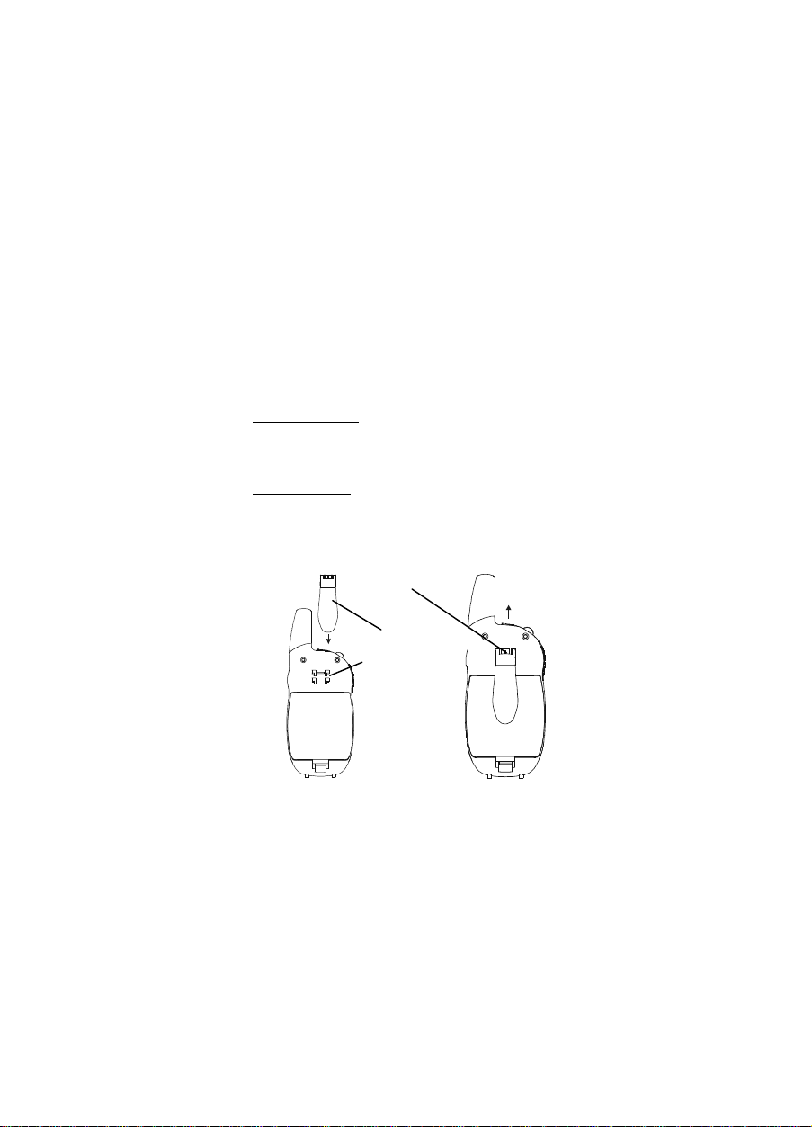
1. Slide the belt chip into place into the belt chip slot as
shown on figure 3.
2. Ensure you hear a click, to indicate that it is securely in
place.
Removing Belt Clip
1. Pull the belt clip latch away from the unit. as shown on
figure 4.
2. While pulling the belt clip latch, push up on the belt
clip to remove it from the unit.
(Figure 3)
Belt Clip Latch
Belt Clip
Belt Clip Slot
(Figure 4)
102106A-1 9
Page 10

TELEPHONE OPERATION
Turning the Unit ON
Press and hold the power button for at least 2 seconds. The
unit will beep, the LCD panel will display information about
you radio, and the panel will be illuminated by a light for
several seconds.
Turning the Unit OFF
Press and hold the power button for at least 2 seconds. The
unit will bee p.
Adjusting the Volume
Press the UP button to increase volume. Press the DN button
Adjusting the Volume to decrease volume.
Receiving a Call
The unit is continuously on receive mode when the unit is
ON.
Transmitting a call
Press and hold the CALL button to transmit. The green LED
will light up. The other unit will ma ke a 2 second c all tone.
NOTE: In order for other people to receive your
transmission, they must also be on the same channel yo u are
curre ntly usin g. Refer to the “Cha nging Cha nnels” s ection
for more information.
Changing Channels
1. Press the MENU button. The channel number on the
display p anel will be gin to flash.
2. While the number is flashing, press the up or down
buttons until you reach the desired channel.
10 102106A-1
Page 11

3. Press the MENU button to confirm.
4. Press UP or DN button to select desired ca lling r inger (1,
2 , 3 , 4 , 5 , 0 =off ).
5. Press the MENU button again to set the channel.
Channel scan
Your radio can scan across 22 channels for any activity. This
allows you find other radios without having to change
channels.
1. Pres s t he SC AN b utto n (T he c ha nnel d is pla y wi ll cha nge
as it scans through the channels).
2. Press the TALK or MENU button to stop the scan and
communicate.
Monitor
You can use the MONITOR feature to listen in for weak
signals in the current channel.
• Press t he MONITO R Button for normal monitoring.
• Press and hold the MONITOR Button for at least
three s econds fo r continuous monitoring.
Channel Lock
This feature locks the channel adjustment buttons on the
front to the unit so that the channel can not be changed
accidentally .
To Lock the channel:
Press and hold the MENU and UP buttons together for 2
seconds until you hear a “beep” sound ,The lock symbol
(shape d like a key ) will appear on the LCD display.
To Unlock the channel :
Press and hold the MENU and UP buttons together for 2
seconds until you hear a “beep” sound again ,The lock
symbol in the LCD display will disappear.
102106A-1 11
Page 12
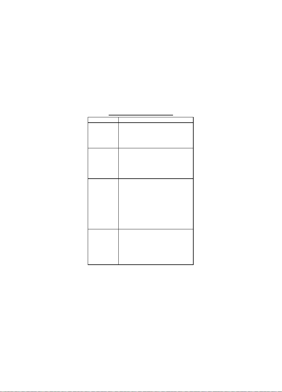
TROUBLESHOOTING
D
on
SYMPTOM SOLUTION
oes not turn
Reception is
weak
Rang is
limited
Sound
distortion
problems
• Check batteries. Ensure that the
batteries are installed properly.
• The batteries may be weak.
Replace old batteries with eight
new “AAA” Alkaline batteries.
• Press the UP button to increase
volume.
• The receiving signal may be
week and out of range. If this
happens, press the MONITOR
button.
• Batteries may be weak. Replace
with new batteries if the battery
level indicator is lo w.
• The maximum range will vary
depending on terrain and
environment. Open fields
provide the maximum range,
while buildings and other
structures may limit the range
significantly.
• If you are transmitting, speak in
a normal tone of voice, 2 to 3
inches away from the
microphone.
• If you are receiving, lower the
volume control to a comfortable
level.
12 102106A-1
Page 13

102106A-1 13
99152/102106A-1
 Loading...