

Page 1
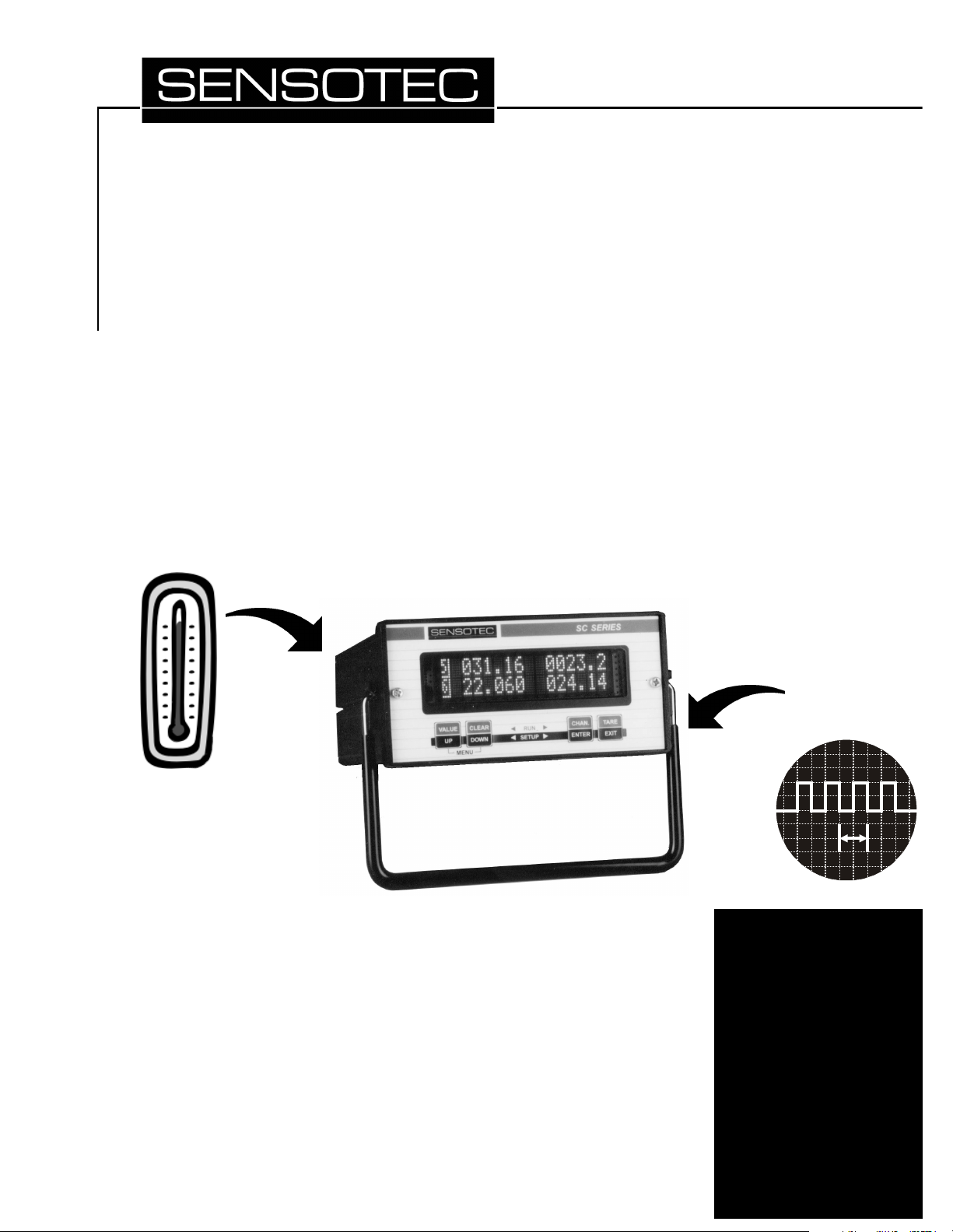
Additional Channels for SC Instrumentation
Temperature (RTD) Input,
Frequency Input
Pressure
Transducers
Load & Torque
Cells
Accelerometers
Displacement
Transducers
Instrumentation
Page 2
Sensotec, Inc.
2080 Arlingate Lane
Columbus, Ohio 43228 USA
Copyright © 2002 by Sensotec, Inc. all rights reserved
Telephone: (614)850-5000
FAX: (614)850-1111
Toll Free: 1-800-848-6564
E-mail: [email protected]
WWW: http://www.sensotec.com
Additional Channels for SC Series Instrumentation
Sensotec Document Number: 008-0608-01
Rev. -: March, 2002
IMPORTANT It is recommended that you read the “SC Series Instruction Manual”, Sen-
sotec document 008-0608-00 before using the channels described herein.
CAUTION: The operator of this instrument is advised that if the equipment
is not used in a manner not specified in this manual, the protection provided by the equipment may be impaired.
CAUTION: Only qualified, service-trained personnel who are aware of the
hazards involved should remove the cover from the instrument or connect
external wiring to the instrument.
Sensotec and the Sensotec logo are registered trademarks of Sensotec,
Inc.
Printed in U.S.A.
Sensotec continually improves its products, and thus the information herein
is subject to change without notice.
Page 3
Contents
CONTENTS
Contents . . . . . . . . . . . . . . . . . . . . . . . . . . . . . . . . . .
Chapter 1
Introduction . . . . . . . . . . . . . . . . . . . . . . . . . . . . . . . .
1.1 About This Manual . . . . . . . . . . . . . . . . . . . . . . .
1.1.1 Scope . . . . . . . . . . . . . . . . . . . . . . . . . . . . . . . . . . . . . . 5
1.1.2 Conventions . . . . . . . . . . . . . . . . . . . . . . . . . . . . . . . . . 5
1.1.3 Organization . . . . . . . . . . . . . . . . . . . . . . . . . . . . . . . . 5
1.2 Related Documents . . . . . . . . . . . . . . . . . . . . . .
Chapter 2
RTD Input Channel . . . . . . . . . . . . . . . . . . . . . . . . . .
2.1 Features . . . . . . . . . . . . . . . . . . . . . . . . . . . . . . .
2.2 Getting Started Quickly . . . . . . . . . . . . . . . . . . . .
2.3 Wiring . . . . . . . . . . . . . . . . . . . . . . . . . . . . . . . . .
2.3.1 Channel Connector . . . . . . . . . . . . . . . . . . . . . . . . . . . 10
2.3.2 4-Wire RTD Connection . . . . . . . . . . . . . . . . . . . . . . . . 10
2.3.3 3-Wire RTD Connection . . . . . . . . . . . . . . . . . . . . . . . . 11
2.3.4 2-Wire RTD Connection . . . . . . . . . . . . . . . . . . . . . . . . 11
2.4 Calibration . . . . . . . . . . . . . . . . . . . . . . . . . . . . . .
2.5 Channel Specifications . . . . . . . . . . . . . . . . . . . .
2.6 Channel Menu . . . . . . . . . . . . . . . . . . . . . . . . . . .
2.6.1
OPER
OPERAAAATION
TION
OPEROPER
2.6.2
DISP
DISPLLLLAY UNITS
DISPDISP
2.6.3
AUXn
AUXn FUNCTION
AUXnAUXn
2.6.4
CALI
CALIBBBBRATION T
CALICALI
2.6.5
CALI
CALIBBBBRATION D
CALICALI
2.6.6
CALI
CALIBBBBRATE
CALICALI
2.6.7
DAC
DAC SSSSETUP
DACDAC
2.6.8
DIAG
DIAGNNNNOSTICS
DIAGDIAG
Sub-Menu . . . . . . . . . . . . . . . . . . . . . . . . . 14
TIONTION
AY UNITS
AY UNITSAY UNITS
FUNCTION
FUNCTIONFUNCTION
RATION TYYYYPE
RATION TRATION T
RATION DAAAATA
RATION DRATION D
RATE
RATERATE
ETUP
ETUPETUP
OSTICS
OSTICSOSTICS
Menu Item . . . . . . . . . . . . . . . . . . . . . 15
Menu Items . . . . . . . . . . . . . . . . . . . . 15
PE
Menu Item . . . . . . . . . . . . . . . . . . . 16
PEPE
TA
Sub-Menu . . . . . . . . . . . . . . . . . . . 17
TATA
Menu Item . . . . . . . . . . . . . . . . . . . . . . . . . 17
Sub-Menu . . . . . . . . . . . . . . . . . . . . . . . . . 19
Sub-Menu . . . . . . . . . . . . . . . . . . . . . . . 20
2.7 Analog Output Configuration . . . . . . . . . . . . . . . .
2.7.1 Identifying the Output Type . . . . . . . . . . . . . . . . . . . . . 21
2.7.2 Channel Menu Items . . . . . . . . . . . . . . . . . . . . . . . . . . 21
2.7.3 Output Selection . . . . . . . . . . . . . . . . . . . . . . . . . . . . . 21
2.8 Troubleshooting . . . . . . . . . . . . . . . . . . . . . . . . .
2.8.1 Error Messages . . . . . . . . . . . . . . . . . . . . . . . . . . . . . . 22
2.8.2 Common Problems and Solutions . . . . . . . . . . . . . . . . 22
2.9 Communication Commands . . . . . . . . . . . . . . . .
2.9.1 Introduction . . . . . . . . . . . . . . . . . . . . . . . . . . . . . . . . . 23
2.9.2 Descriptions . . . . . . . . . . . . . . . . . . . . . . . . . . . . . . . . . 23
3
5
5
6
9
9
9
10
12
13
14
21
22
23
Chapter 3
Frequency Input Channel . . . . . . . . . . . . . . . . . . . . .
3.1 Features . . . . . . . . . . . . . . . . . . . . . . . . . . . . . . .
3.2 Getting Started Quickly . . . . . . . . . . . . . . . . . . . .
3.3 Wiring . . . . . . . . . . . . . . . . . . . . . . . . . . . . . . . . .
3.3.1 Channel Connector . . . . . . . . . . . . . . . . . . . . . . . . . . . 34
Additional Channels for SC Series Instrumentation page 3
33
33
33
34
Page 4
3.3.2 NPN Open-Collector Connection . . . . . . . . . . . . . . . . . 34
3.3.3 PNP Open-Collector . . . . . . . . . . . . . . . . . . . . . . . . . . . 35
3.3.4 TTL/CMOS Logic Connection . . . . . . . . . . . . . . . . . . . 35
3.3.5 Magnetic Pickup Connection . . . . . . . . . . . . . . . . . . . . 35
3.4 Calibration . . . . . . . . . . . . . . . . . . . . . . . . . . . . .
3.5 Channel Specifications . . . . . . . . . . . . . . . . . . . .
3.6 Channel Menu . . . . . . . . . . . . . . . . . . . . . . . . . .
3.6.1
OPER
OPERAAAATION
TION
OPEROPER
3.6.2
AUXn
AUXn FUNCTION
AUXnAUXn
3.6.3
CALI
CALIBBBBRATION T
CALICALI
3.6.4
CALI
CALIBBBBRATION D
CALICALI
3.6.5
CALI
CALIBBBBRATE
CALICALI
3.6.6
DAC
DAC SSSSETUP
DACDAC
3.6.7
DIAG
DIAGNNNNOSTICS
DIAGDIAG
Sub-Menu . . . . . . . . . . . . . . . . . . . . . . . . . . 38
TIONTION
FUNCTION
FUNCTIONFUNCTION
RATION TYYYYPE
RATION TRATION T
RATION DAAAATA
RATION DRATION D
RATE
RATERATE
ETUP
ETUPETUP
OSTICS
OSTICSOSTICS
Menu Items . . . . . . . . . . . . . . . . . . . . . 38
PE
Menu Item . . . . . . . . . . . . . . . . . . . 39
PEPE
TA
Sub-Menu . . . . . . . . . . . . . . . . . . . 40
TATA
Menu Item . . . . . . . . . . . . . . . . . . . . . . . . . 40
Sub-Menu . . . . . . . . . . . . . . . . . . . . . . . . . . 41
Sub-Menu . . . . . . . . . . . . . . . . . . . . . . . . 42
3.7 Analog Output Configuration . . . . . . . . . . . . . . .
3.7.1 Identifying the Output Type . . . . . . . . . . . . . . . . . . . . . 43
3.7.2 Channel Menu Items . . . . . . . . . . . . . . . . . . . . . . . . . . 43
3.7.3 Output Selection . . . . . . . . . . . . . . . . . . . . . . . . . . . . . . 43
3.8 Troubleshooting . . . . . . . . . . . . . . . . . . . . . . . . .
3.8.1 Error Messages . . . . . . . . . . . . . . . . . . . . . . . . . . . . . . 44
3.8.2 Common Problems and Solutions . . . . . . . . . . . . . . . . 44
3.9 Communication Commands . . . . . . . . . . . . . . . .
3.9.1 Introduction . . . . . . . . . . . . . . . . . . . . . . . . . . . . . . . . . 45
3.9.2 Descriptions . . . . . . . . . . . . . . . . . . . . . . . . . . . . . . . . . 45
36
37
38
43
44
45
Chapter 4
Setup Menu Reference . . . . . . . . . . . . . . . . . . . . . . .
4.1 Navigation instructions . . . . . . . . . . . . . . . . . . . .
Index . . . . . . . . . . . . . . . . . . . . . . . . . . . . . . . . . . . . .
Warranty/Repair Policy . . . . . . . . . . . . . . . . . . . . . .
55
55
59
61
page 4 008-0608-01
Page 5
Chapter 1
1.1 About This Manual
1.1.1 Scope
1.1.2 Conventions
This manual will explain the setup, features and operation of additional Input and
Output channels that may be installed into Sensotec’s 3rd generation SC SEries
instruments. This series includes the models SC1000, SC2000, SC2001 and
SC3004.
This manual uses the following conventions to present information:
Introduction
[TEXT IN BRACKETS] The label of a front panel button.
DDDDIIIISSSSPPPPLLLLAAAAYYYY
-> Indicates that what follows is an item from a sub-
DATA
Text that appears on the display, such as error
messages or menu items.
menu, such as
Serial communications commands sent to (or
replies from) the instrument
SSSSYYYYSSSSTTTTEEEEMMMM MEN
MENUUUU
MENMEN
->
DDDDIIIIAAAAGGGGNNNNOOOOSSSSTTTTIIIICCCCSSSS
.
INTRODUCTION1
1.1.3 Organization
↵ The carriage-return character, ASCII code decimal
13
Notes contain important information set off from
Note
Chapter 1, “Introduction”, offers general information about this instruction manual.
Chapter 2, “RTD Input Channel”, explains how to wire, configure, operate and
calibrate the RTD Input channel.
Chapter 3, “Frequency Input Channel”, explains how to wire, configure, operate and calibrate the Frequency Input channel.
Chapter 4, “Setup Menu Reference”, is a list of all SETUP menus and a crossreference to related information in this instruction manual.
the text.
A stop sign highlights procedures or information
necessary to avoid damage to equipment, damage to software, loss of data, loss of calibration, or
invalid test results.
The caution symbol alerts that a specific procedure or practice which, is not followed correctly,
could cause serious personal injury.
Additional Channels for SC Series Instrumentation page 5
Page 6

1.2 Related Documents
SC Series Instruction
Manual
Customer Information
Sheet
The “SC Series Instruction Manual”, Sensotec p/n 008-0608-00, describes the wiring,
setup and operation of the chassis and channels of SC Series Instruments. The channels described in this document are:
• Strain-Gage Input channel
• AC/AC-LVDT Input channel
• High-Level Input channel
• Relay Output channel
• DAC Output channel
• Split-Display Virtual channel
• Mathematics Virtual channel
A printed copy of this document is available for order, or you may download it for free
Sensotec’s web site, www.sensotec.com.
Every instrument is shipped with a Customer Information Sheet which documents the
configuration of the instrument when it left the factory. Such information includes:
• Sensotec part number,
• date of manufacture,
• list of all installed channels and their setup information,
• customer specific SensoCode programming of Mathematics Virtual channels and
operation notes.
Communications
Guide
The “SC Series Communications Guide”, Sensotec p/n 008-0610-00, describes in
detail how to communicate with an SC Series instrument using RS-232 and RS-485.
Wiring diagrams, sample programs, and command descriptions are included.
A printed copy of this document is available for order, or you may download it for free
Sensotec’s web site, www.sensotec.com.
page 6 008-0608-01
Page 7

INTRODUCTION1
Additional Channels for SC Series Instrumentation page 7
Page 8

page 8 008-0608-01
Page 9

2.1 Features
Chapter 2
RTD Input Channel
The RTD Input channel provides a DC excitation current to and accepts millivolt
signals from a standard platinum, 100Ω Resistance Temperature Detector (RTD).
These signals are digitized, converted into engineering units, and placed into the
track, peak and valley data values of the channel.
Setup and calibration of the channel is made at the factory for operation with a
customer-supplied Pt-100 RTD with a DIN-43760 standard calibration curve. Recalibration can be made manually through the SETUP mode with the known-load
calibration method and a customer-supplied RTD calibrator.
The engineering units used to display the temperature readings are field selectable from a built-in conversion table. In addition, the engineering units used for
calibration can be independently selected.
Two rear panel control inputs can be field-configured for such functions as remote
track/hold, disabling peak/valley detection and clearing the peak/valley values. A
voltage or current digital-to-analog output is also provided.
2.2 Getting Started Quickly
As shipped from the factory, the RTD Input channel is calibrated for a standard
Pt100 (platinum, 100Ω @ 100ºC) RTD that conforms to the DIN-43760 / IEC751
standards (∝=0.00385). No further calibration is required prior to use.
Connect the RTD to the RTD Input channel according to “Wiring” on page 10.
RTD INPUT CHANNEL2
Additional Channels for SC Series Instrumentation page 9
Page 10
2.3 Wiring
2.3.1 Channel Connector
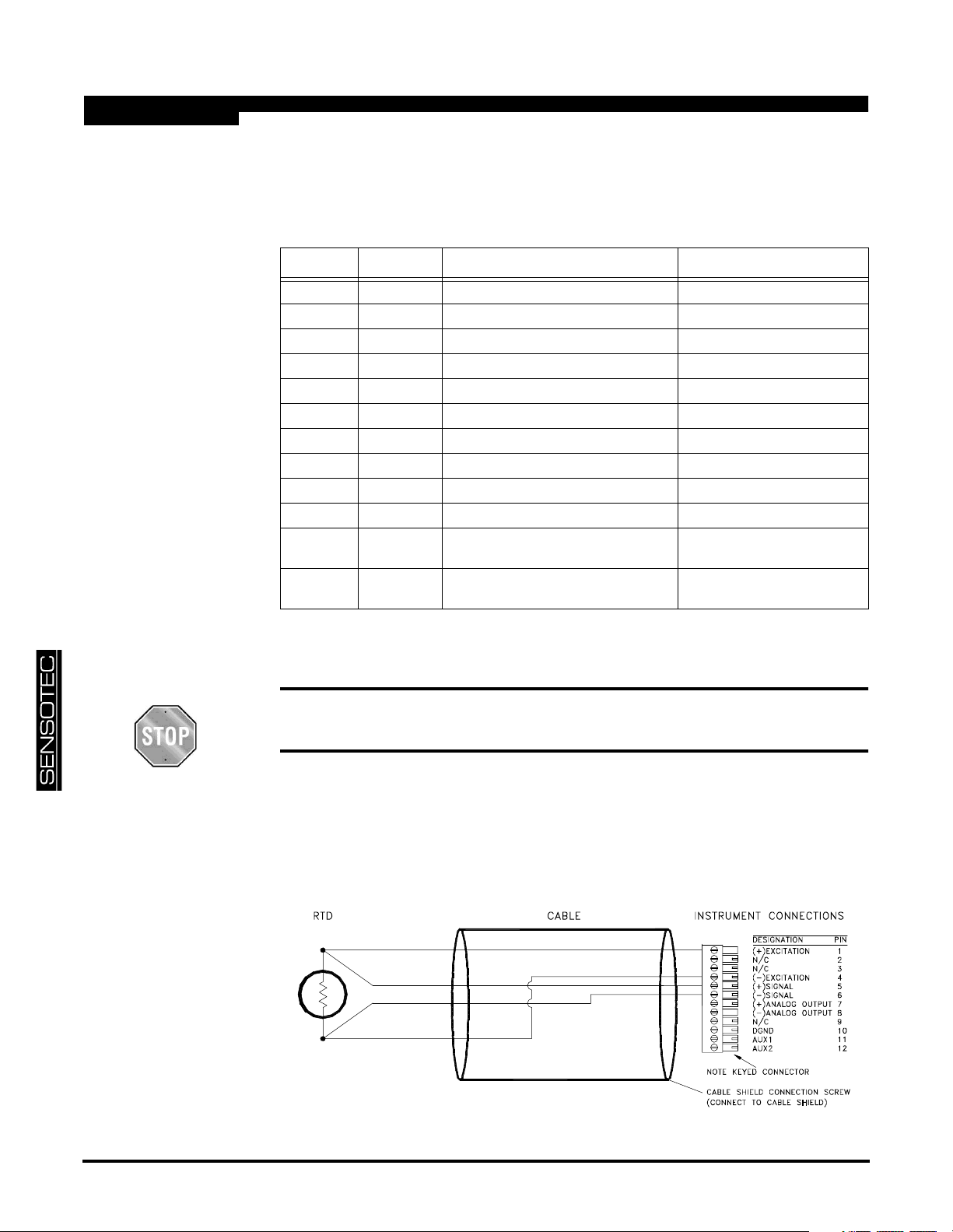
The pin-out for the channel’s connector is shown in the following table.
Table 2-1: RTD Input Channel Pin Connections
Pin Label Function NOTES
1 (top) +EXC (+)Excitation referenced to pin 10
2N/C N/C DO NOT CONNECT!
3N/C N/C DO NOT CONNECT!
4 -EXC (-)Excitation referenced to pin 10
5 +SIG (+)Signal referenced to pin 10
6 -SIG (-)Signal referenced to pin 10
7 +OUT Analog Output referenced to pin 8
8 -OUT Analog Return -
9N/C N/C DO NOT CONNECT!
10 DGND Digital Ground -
11 AUX1 Auxiliary Function 1
(connect to pin 10 to activate)
12
(bottom)
The Analog Output and Analog Return pins are electrically isolated from all other pins
on the instrument.
AUX2 Auxiliary Function 2
(connect to pin 10 to activate)
referenced to pin 10
referenced to pin 10
2.3.2 4-Wire RTD Connection
Do not connect anything to the pins labeled as “N/C”. Damage to the instru-
ment or loss of accuracy may result.
Use a 4-wire RTD connection when the highest possible accuracy is desired. The
excitation current from the instrument will be carried by two wires and the voltage drop
across the RTD will be sensed with the other two wires. Since the (+)Signal and ()Signal pins are high impedance inputs, there is little current flow through these wires
therefore the resistance of the wires doesn’t add to the resistance of the RTD.
Figure 2-1: “4-wire RTD Connection” to RTD Input Channel
page 10 008-0608-01
Page 11
2.3.3 3-Wire RTD Connection
2.3.4 2-Wire RTD Connection
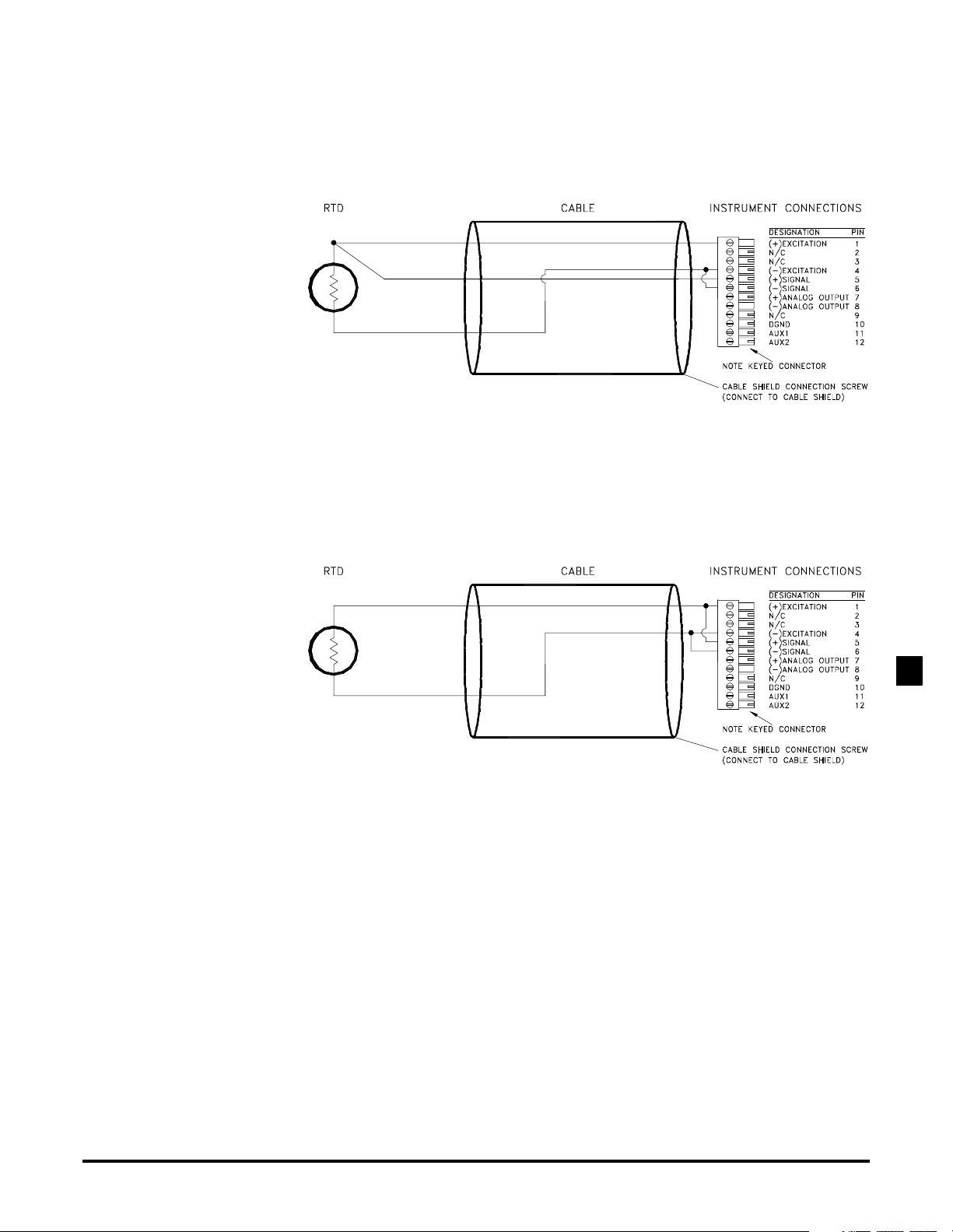
If the cost of 4-wire cable is an issue, it is possible to use a 3-wire RTD connection that shares many of the benefits of the 4-wire connection. The wire lengths
should be equal and the wire type should be identical. This will equalize wire
resistance and thus obtain the best accuracy.
Figure 2-2: “3-Wire RTD” Connection to RTD Input Channel
The 2-wire connection scheme is not recommended unless the cable length is
short. The wire’s resistance will add to the resistance of the RTD and result in
reduced accuracy.
Figure 2-3: “2-Wire RTD Connection” to RTD Input Channel
RTD INPUT CHANNEL2
Additional Channels for SC Series Instrumentation page 11
Page 12
2.4 Calibration
A listing of all menu items for this channel is given in “Setup Menu Reference” on
page 55.
A customer-supplied RTD simulator/calibrator is required for re-calibration.
Although not recommended, field re-calibration of the channel for operation
with RTDs with outputs other than the Pt100 DIN-43760 / IEC751 standards
can be made; this may result in reduced accuracy and resolution.
Step 1: Wire the RTD simulator/calibrator to the channel’s connector.
See “Wiring” on page 10.
Step 2: Enter the
See “
CALIBRATION DATA
CCCCAAAALLLLIB
IBRRRRAAAATTTTIIIIOOOONNNN DAT
IBIB
.
DATAAAA
DATDAT
Sub-Menu” on page17.
If you wish to re-calibrate the instrument using a unit-of-measure other than
degrees Celsius, you can use the
CCCCAL
ALIIIIBBBBRRRRAAAATTTTIIIIOOOON U
ALAL
NUNNNNIIIITTTTSSSS
NUNU
menu item to change the
units-of-measure that the instrument uses for calibration.
Step 3: Perform the calibration.
See “
CALIBRATE
Using the
Menu Item” on page 17.
CCCCAAAALLLLIIIIBBBBRRRRAAAATTTTEEEE
menu item starts the calibration process. You will be
prompted to use your RTD simulator/calibrator to apply simulated RTD signals
to the channel as required.
page 12 008-0608-01
Page 13

2.5 Channel Specifications
Absolute Accuracy of Factory Calibra-
RTD INPUT
Excitation Current 0.25mA
Factory Calibration For use with Pt100 RTD that use DIN-
43760 / IEC751 standard (∝=0.00385)
±0.5ºC max. from -200ºC to +200ºC
tion
Resolution ±0.2ºC
A/D Converter 24-bit Sigma-Delta
Low-pass filter digital, 24-tap FIR
Frequency Response 16 Hz
Step Response 55 ms (typical)
Maximum Input Resistance ~250Ω
AUXILLIARY INPUTS
Quantity 2
Type momentary contact closure
Response Time < 5ms
Field-Selectable Functions peak/valley clear, peak/valley hold,
ANALOG OUTPUT
Output voltage range 5, ±5, 10 or ±10 VDC (field selectable)
Output current range (optional current
output channels)
Source any channel’s track, peak or valley value
Isolation 500V
Resolution 13 bits
Frequency Response same as input when driven by the same
track hold
RTD INPUT CHANNEL2
4-20 mA
channel’s tracking data
Additional Channels for SC Series Instrumentation page 13
Page 14
2.6 Channel Menu
The RTD Input channel is configured and calibrated via its channel menu. Detailed
instructions on operating the instrument in the SETUP Menu mode can be found in
the “SC Series Instruction Manual”, Sensotec p/n 008-0608-00.
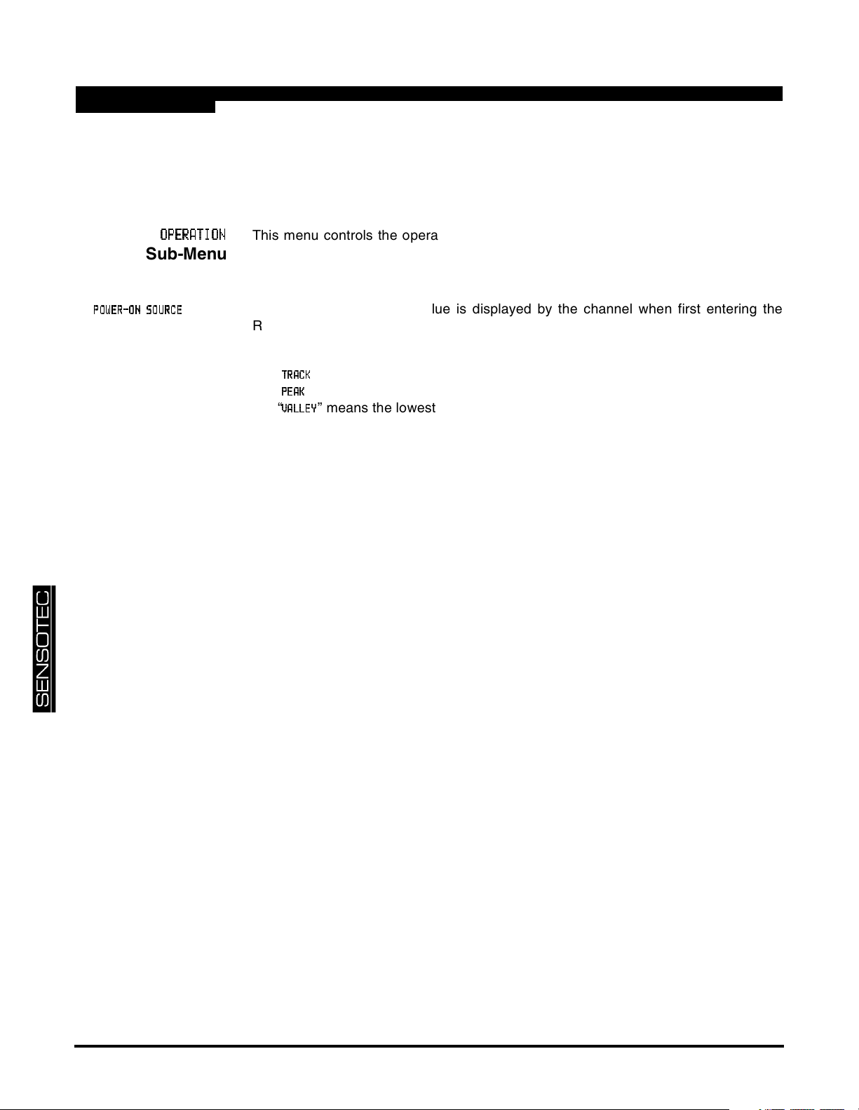
2.6.1
OP
OPEEEERATION
OPOP
Sub-Menu
PPPPOOOOWWWWEEEERRRR----OOOONNNN SOURC
SOURCEEEE
SOURCSOURC
RATION
RATIONRATION
Menu
Item
This menu controls the operation of this channel when the instrument is in the RUN
mode.
This menu selects which value is displayed by the channel when first entering the
RUN mode.
The choices are:
•“
•“
•“
” means the live tracking value of the channel.
TTTTRRRRAAAACCCCKKKK
” means the highest value of the channel.
PPPPEEEEAAAAKKKK
” means the lowest value of the channel.
VVVVAAAALLLLLLLLEEEEYYYY
page 14 008-0608-01
Page 15
2.6.2
DISPLA
DISPLAYYYY UNITS
DISPLADISPLA
UNITS
UNITSUNITS
Menu Item
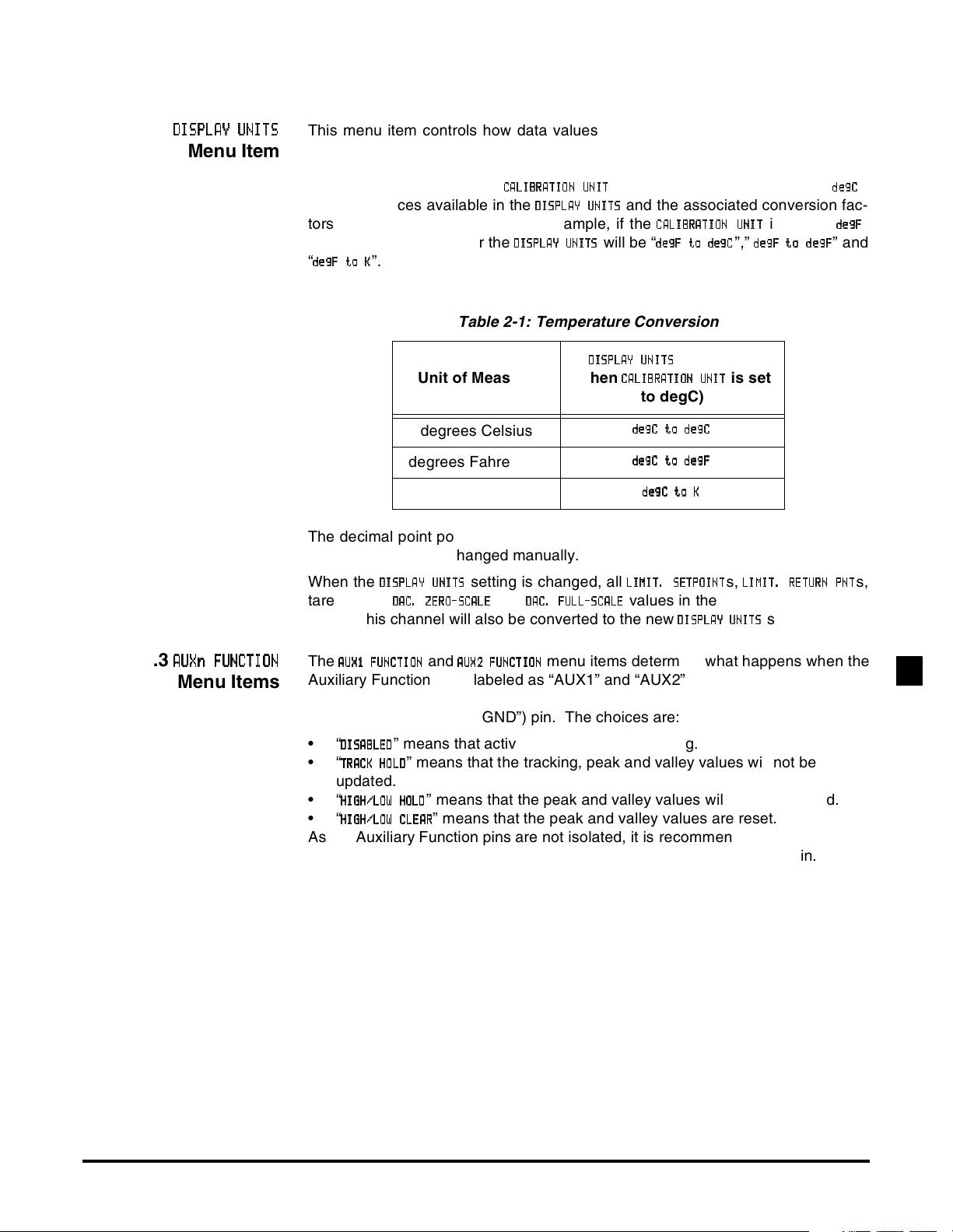
This menu item controls how data values are scaled into engineering units, displayed by the channel, and transmitted via serial communications. The RTD
Input channel has conversion factors for degrees Celsius, degrees Fahrenheit
and Kelvin. Note that if the
then the choices available in the
CCCCAAAALLLLIIIIBBBBRRRRAAAATTTTIIIIOOOON U
DDDDIIIISSSSPPPPLLLLAAAAY UNI
tors will change accordingly. For example, if the
then choices available for the
“
ddddeeeeggggFFFFtttto K
oK
oKoK
”.
DDDDIIIISSSSPPPPLA
LAYYYY UNIT
LALA
is set to something other than “
NUNNNNIIIITTTT
NUNU
Y UNITTTTSSSS
Y UNIY UNI
UNITSSSS
UNITUNIT
and the associated conversion fac-
will be “
CCCCAAAALLLLIIIIBBBBRRRRAAAATTTTIIIIOOOON U
ddddeeeeggggFFFF to deg
to degCCCC
to degto deg
NUNNNNIIIITTTT
NUNU
is set to “
”,”
ddddeeeeggggFFFF to deg
to degFFFF
to degto deg
ddddeeeeggggCCCC
ddddeeeeggggFFFF
” and
Table 2-1: Temperature Conversion
Menu Item
UNITSSSS
UNITUNIT
UNITTTT
UNIUNI
is set
Unit of Measure
DDDDIIIISSSSPPPPLLLLAAAAYYYY UNIT
(when
CCCCAAAALLLLIIIIBBBBRRRRAAAATTTTIIIIOOOONNNN UNI
to degC)
ddddeeeeggggCCCCtod
to deeeeggggCCCC
degrees Celsius
degrees Fahrenheit
Kelvin
to dto d
ddddeeeeggggCCCCtod
to deeeeggggFFFF
to dto d
ddddeeeeggggCCCCto
to KKKK
toto
The decimal point position is set to one decimal place with a resolution of 0.2 ºC,
ºF or K; it cannot be changed manually.
When the
tare values,
DDDDIIIISSSSPPPPLLLLAAAAYYYYUUUUNNNNIIIITTTTSSSS
DDDDAAAACCCC. Z
.ZEEEERRRROOOO----SSSSCCCCAAAALLLLEEEE
.Z.Z
refer to this channel will also be converted to the new
setting is changed, all
and
DDDDAC
AC....FFFFUUUULLLLLLLL----SSSSCA
ACAC
CALLLLEEEE
CACA
LLLLIIIIMMMMIIIITTTT....SSSSEEEETTTTPPPPOOOOIIIINNNNTTTT
s,
LLLLIIIIMMMMIT
IT. R
.REEEETTTTUUUURRRRNNNNPPPPNNNNTTTT
ITIT
.R.R
values in the entire instrument that
DI
DISSSSPPPPLLLLAAAAYYYY UNIT
DIDI
UNITSSSS
UNITUNIT
setting.
”,
”
s,
2.6.3
AUXn F
AUXn FUUUUNCTION
AUXn FAUXn F
NCTION
NCTIONNCTION
Menu Items
The
AAAAUUUUXXXX1 FU
1 FUNNNNCCCCTTTTIIIIOOOONNNN
1 FU1 FU
and
AAAAUUUUXXXX2222FFFFUUUUNNNNCCCCTTTTIIIIOOOONNNN
menu items determine what happens when the
Auxiliary Function pins (labeled as “AUX1” and “AUX2”) on the channel’s connec-
tor are activated. These pins are “activated” when they are connected to the Digital Ground (labeled as “DGND”) pin. The choices are:
•“
DDDDIIIISSSSAAAABBBBLLLLEEEEDDDD
•“
TTTTRRRRAAAACCCCKKKK HOL
” means that activating the pin does nothing.
” means that the tracking, peak and valley values will not be
HOLDDDD
HOLHOL
updated.
•“
HHHHIIIIGGGGHHHH////LLLLOOOOWWWW HOL
•“
HHHHIIIIGGGGHHHH////LLLLOOOOWWWW CLEA
” means that the peak and valley values will not be updated.
HOLDDDD
HOLHOL
” means that the peak and valley values are reset.
CLEARRRR
CLEACLEA
As the Auxiliary Function pins are not isolated, it is recommended that a push-button switch or relay is used to connect these pins to the Digital Ground pin.
RTD INPUT CHANNEL2
Additional Channels for SC Series Instrumentation page 15
Page 16
2.6.4
TYPE
TYPE
Menu Item
TYPETYPE
CALI
CALIBBBBRATION
RATION
CALICALI
RATIONRATION
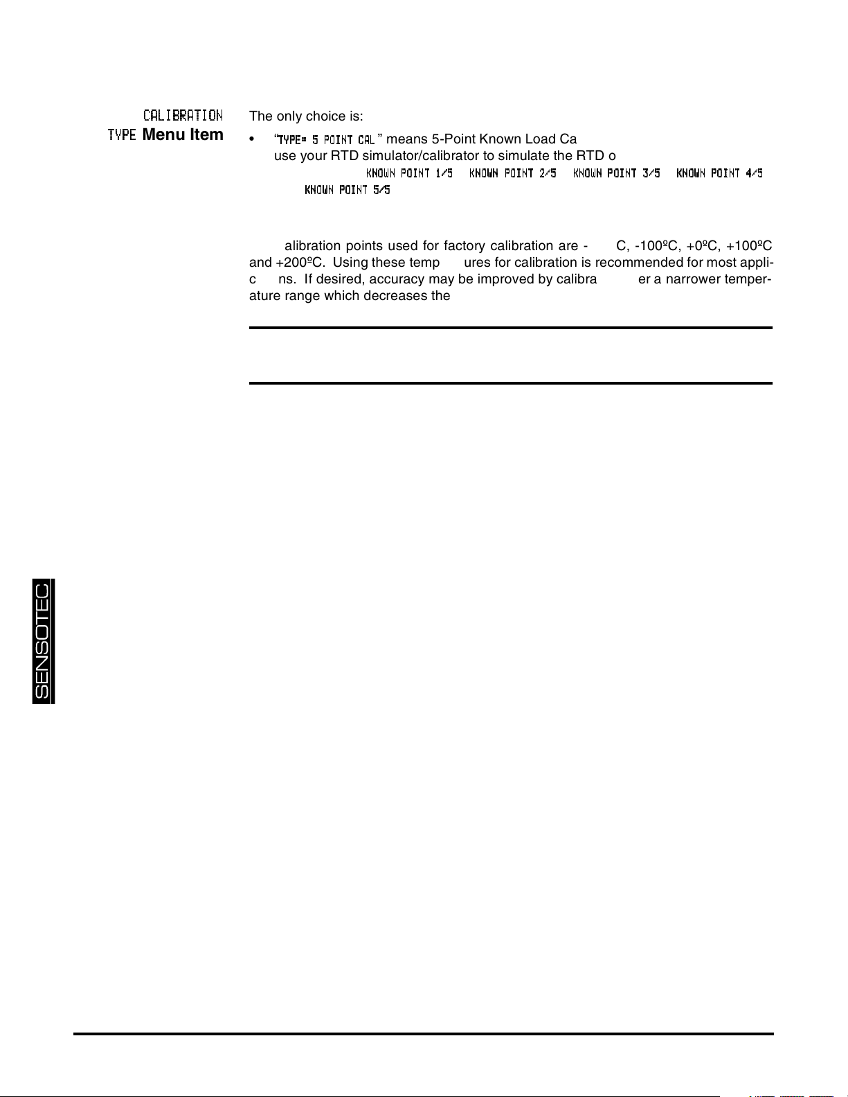
The only choice is:
•“
TTTTYYYYPPPPEEEE====5P
5POOOOIIIINNNNT CA
5P5P
” means 5-Point Known Load Calibration. You are prompted to
TCALLLL
TCATCA
use your RTD simulator/calibrator to simulate the RTD output at the temperatures
entered in the “
and “
KKKKNNNNOOOOWWWWNNNN POINT 5/
POINT 5/5555
POINT 5/POINT 5/
KKKKNNNNOW
OWN P
NPOOOOIIIINNNNTTTT1111////5555
OWOW
NPNP
” registers. This technique is used to compensate for the non-
”, “
KKKKNNNNOOOOWWWWNNNNPPPPOOOOIIIINNNNT 2
T2////5555
T2T2
”, “
KKKKNNNNOOOOWWWWNNNNPPPPOOOOIIIINNNNTTTT3333////5555
”, “
KKKKNNNNOOOOWWWWN P
N POI
NPNP
OINNNNT 4
T4////5555
OIOI
T4T4
linearity inherent in RTDs.
The calibration points used for factory calibration are -200ºC, -100ºC, +0ºC, +100ºC
and +200ºC. Using these temperatures for calibration is recommended for most applications. If desired, accuracy may be improved by calibrating over a narrower temperature range which decreases the difference between the points.
Choosing calibration points where the difference between points is larger than
100ºC will result in greatly reduced accuracy.
”
page 16 008-0608-01
Page 17
2.6.5
CALIBRATI
CALIBRATIOOOON DATA
CALIBRATICALIBRATI
N DATA
N DATAN DATA
Sub-Menu
CCCCAL
ALIIIIBBBBRRRRAAAATTTTIIIIOOOONNNN UNI
ALAL
KKKKNNNNOOOOWWWWNNNN POINT x/
POINT x/yyyy
POINT x/POINT x/
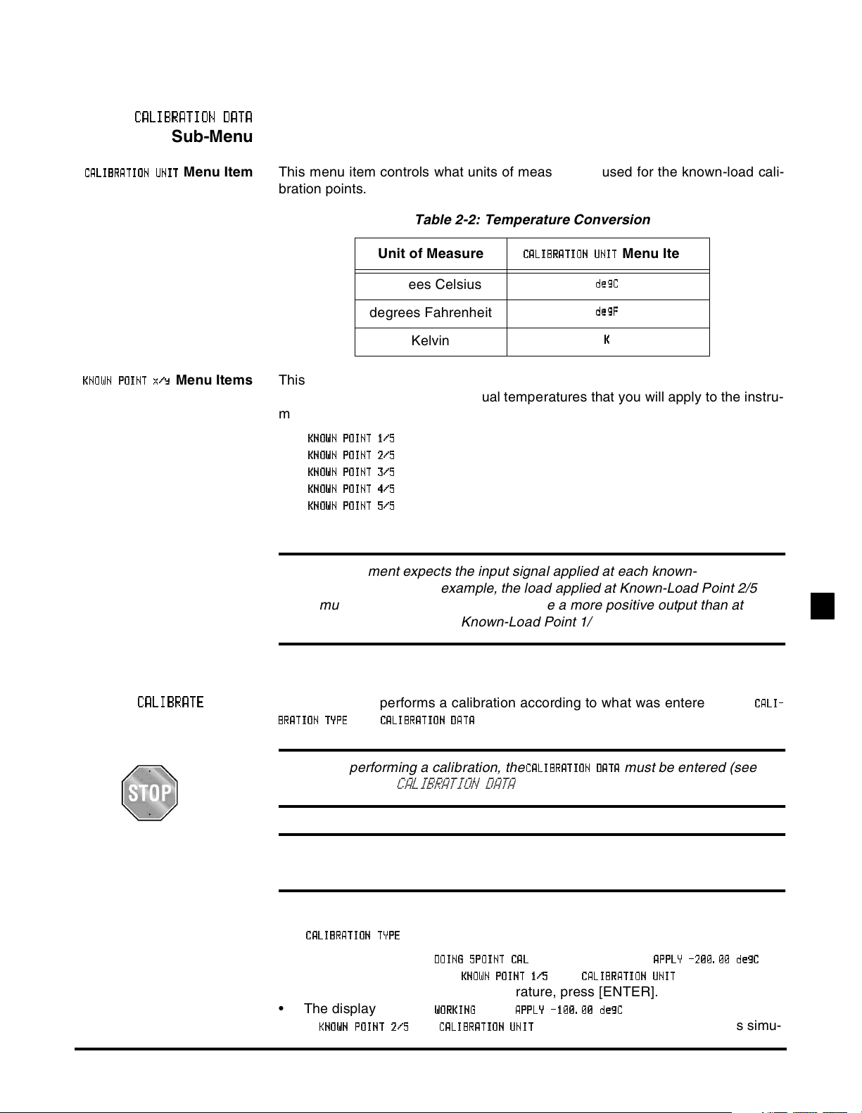
Menu Item This menu item controls what units of measure are used for the known-load cali-
UNITTTT
UNIUNI
bration points.
Table 2-2: Temperature Conversion
Unit of Measure
degrees Celsius
degrees Fahrenheit
Kelvin
CCCCAAAALLLLIB
IBRRRRAAAATTTTIIIIOOOONNNN UNI
IBIB
Menu Item
UNITTTT
UNIUNI
ddddeeeeggggCCCC
ddddeeeeggggFFFF
KKKK
Menu Items This enters the engineering unit values for the known-load calibration points.
These points must match the actual temperatures that you will apply to the instrument during calibration. The following menu items are available:
•“
KKKKNNNNOOOOWWWWNNNN POINT 1/
•“
KKKKNNNNOOOOWWWWNNNN POINT 2/
•“
KKKKNNNNOOOOWWWWNNNN POINT 3/
•“
KKKKNNNNOOOOWWWWNNNN POINT 4/
•“
KKKKNNNNOOOOWWWWNNNN POINT 5/
POINT 1/5555
POINT 1/POINT 1/
POINT 2/5555
POINT 2/POINT 2/
POINT 3/5555
POINT 3/POINT 3/
POINT 4/5555
POINT 4/POINT 4/
POINT 5/5555
POINT 5/POINT 5/
”: point 1 of 5, usually -200ºC.
”: point 2 of 5, usually -100ºC.
”: point 3 of 5, usually 0 ºC.
”: point 4 of 5, usually +100ºC.
”: point 5 of 5, usually +200ºC.
The instrument expects the input signal applied at each known-load point
to be increasing. For example, the load applied at Known-Load Point 2/5
must cause the transducer to produce a more positive output than at
Known-Load Point 1/5.
RTD INPUT CHANNEL2
2.6.6
CALIBRAT
CALIBRATEEEE
CALIBRATCALIBRAT
Menu
Item
This menu item performs a calibration according to what was entered in the
and
BBBBRRRRAAAATTTTIIIIOOOONNNN TYP
TYPEEEE
TYPTYP
CCCCAAAALLLLIIIIBBBBRRRRAAAATTTTIIIIOOOONNNN DAT
Before performing a calibration, the
“
CALIBRATION DATA
menu items.
DATAAAA
DATDAT
CCCCAAAALLLLIIIIBBBBRRRRAAAATTTTIIIIOOOON D
must be entered (see
NDAAAATTTTAAAA
NDND
Sub-Menu” on page 17).
For maximum accuracy, allow at least five minutes of warm-up before cal-
ibration.
The
CCCCAAAALLLLIIIIBBBBRRRRAAAATTTTIIIIOOOONNNN TYP
• The display will read
whatever the settings of
is 5-Point Known Load Calibration.
TYPEEEE
TYPTYP
DDDDOOOOIIIINNNNGGGG5555PPPPOI
OINNNNTTTTCCCCAAAALLLL
OIOI
KNOWN P
KNOWN POOOOIIIINNNNT 1/
KNOWN PKNOWN P
, and prompt you to
and
T1/5555
T1/T1/
AAAAPPPPPPPPLLLLYYYY----222200000000....00000000 deg
CCCCAAAALLLLIIIIBBBBRRRRAAAATTTTIIIIOOOONNNN UNI
UNITTTT
UNIUNI
degCCCC
degdeg
are). When you
have applied this simulated temperature, press [ENTER].
• The display will read
of
KKKKNNNNOOOOWWWWNNNN POINT 2
POINT 2////5555
POINT 2POINT 2
and
, then
WWWWOOOORRRRKKKKIIIINNNNGGGG
CA
CALLLLIIIIBBBBRRRRAAAATTTTIIIIOOOONNNN UNI
CACA
AAAAPPPPPPPPLLLLYYYY -100.00 d
-100.00 deg
-100.00 d-100.00 d
are). When you have applied this simu-
UNITTTT
UNIUNI
(or whatever the settings
egCCCC
egeg
Additional Channels for SC Series Instrumentation page 17
CCCCAAAALLLLIIII----
(or
Page 18
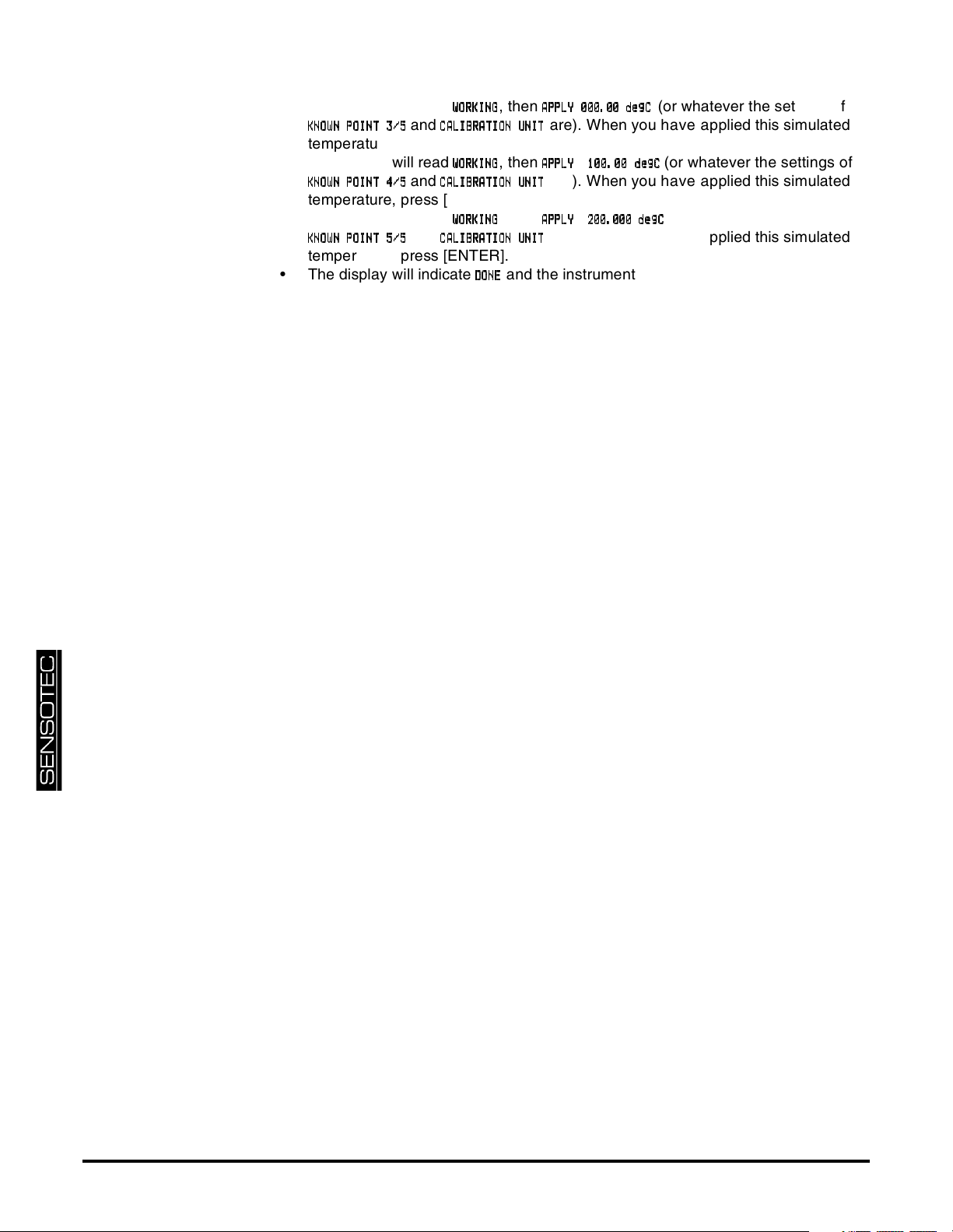
lated temperature, press [ENTER].
• The display will read
KKKKNNNNOOOOWWWWNNNN POINT 3
POINT 3/5
POINT 3POINT 3
/5
/5/5
and
WWWWOOOORRRRKKKKIIIINNNNGGGG
CCCCAAAALLLLIIIIBBBBRRRRAAAATTTTIIIIOOOONNNN UNI
temperature, press [ENTER].
• The display will read
KKKKNNNNOOOOWWWWNNNN POINT 4
POINT 4/5
POINT 4POINT 4
/5
/5/5
and
WWWWOOOORRRRKKKKIIIINNNNGGGG
CCCCAAAALLLLIIIIBBBBRRRRAAAATTTTIIIIOOOONNNN UNI
temperature, press [ENTER].
• The display will read
KKKKNNNNOOOOWWWWNNNN POINT 5
POINT 5/5
POINT 5POINT 5
/5
/5/5
and
WWWWOOOORRRRKKKKIIIINNNNGGGG
CCCCAAAALLLLIIIIBBBBRRRRAAAATTTTIIIIOOOONNNN UNI
temperature, press [ENTER].
• The display will indicate
DDDDOOOONNNNEEEE
, then
AAAAPPPPPPPPLLLLYYYY 000.00 d
000.00 deeeeggggCCCC
000.00 d000.00 d
are). When you have applied this simulated
UNITTTT
UNIUNI
, then
AAAAPPPPPPPPLLLLYYYY 100.00 d
100.00 deg
100.00 d100.00 d
are). When you have applied this simulated
UNITTTT
UNIUNI
, then
AAAAPPPPPPPPLLLLYYYY 200.000 d
200.000 deeeeggggCCCC
200.000 d200.000 d
are). When you have applied this simulated
UNITTTT
UNIUNI
(or whatever the settings of
(or whatever the settings of
egCCCC
egeg
(or whatever the settings of
and the instrument will return to the RUN mode.
page 18 008-0608-01
Page 19
2.6.7
DDDDAAAACCCC.... CHANNE
CHANNELLLL
CHANNECHANNE
DDDDAAAACCCC.... SOURC
SOURCEEEE
SOURCSOURC
DA
DACCCC SETUP
SETUP
DADA
SETUPSETUP
Sub-Menu
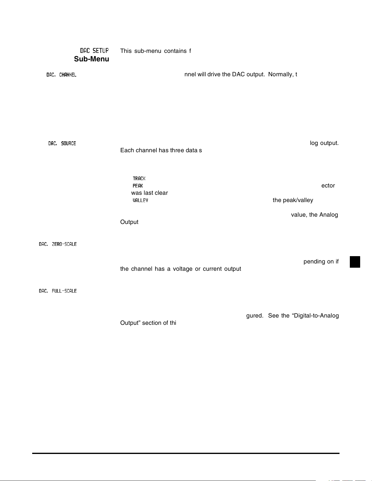
This sub-menu contains four items that control the Digital-to-Analog Converter
(DAC) output of the channel.
Menu Item This chooses which channel will drive the DAC output. Normally, the DAC located
on a particular channel will be driven by that channel, but that need not be the
case. For example, if a Mathematics Virtual channel is installed on the instrument, the output of this Virtual channel could be used to drive this channel’s DAC
output.
If the DAC is set-up to be driven by its own channel’s tracking value, the Analog
Output will have the frequency response specified by “Channel Specifications” on
page 13. Otherwise, the Analog Output will operate more slowly.
Menu Item This designates the data source of the channel monitored by the analog output.
Each channel has three data sources: the live tracking value (TRACK), its highest
value (PEAK), and its lowest value (VALLEY).
The options for this menu item are:
•“
•“
” means the live tracking value of the channel.
TTTTRRRRAAAACCCCKKKK
” means the highest value of the channel since the peak/valley detector
PPPPEEEEAAAAKKKK
was last cleared.
•“
” means the lowest value of the channel since the peak/valley detector
VVVVAAAALLLLLLLLEEEEYYYY
was last cleared.
If the DAC is set-up to be driven by its own channel’s tracking value, the Analog
Output will have the frequency response specified by “Channel Specifications” on
page 13. Otherwise, the Analog Output will operate more slowly.
DA
DACCCC.... ZERO-SCAL
ZERO-SCALEEEE
DADA
ZERO-SCALZERO-SCAL
DA
DACCCC.... FULL-SCAL
FULL-SCALEEEE
DADA
FULL-SCALFULL-SCAL
Menu Item This specifies what value, in engineering units, corresponds to zero output on the
Analog Output.
“Zero output” might be 0 Volts, 2.5 Volts, 5 Volts, 4 mA or 12 mA depending on if
the channel has a voltage or current output and how it is configured. See the
“Digital-to-Analog Output” section of this chapter for details.
Menu Item Specifies what value, in engineering units, corresponds to full output on the Ana-
log Output.
“Full output” might be 5 Volts, 10 Volts or 20 mA depending on if the channel has
a voltage or current output and how it is configured. See the “Digital-to-Analog
Output” section of this chapter for details.
RTD INPUT CHANNEL2
Additional Channels for SC Series Instrumentation page 19
Page 20
2.6.8
DIAG
DIAGNNNNOSTICS
OSTICS
DIAGDIAG
OSTICSOSTICS
Sub-Menu
DDDDAAAACCCCFFFFUUUULLLLL S
LSCCCCAAAALLLLEEEE
LSLS
DDDDAAAACCCCZZZZEEEERRRRO S
OSCCCCAAAALLLLEEEE
OSOS
VVVVEEEERRRRSSSSIIIIOOOONNNN INF
LLLLIIIINNNNEEEEAAAARRRRIIIIZZZZAAAATTTTIIIION
INFOOOO
INFINF
DDDDIIIISSSSPPPPLLLLAAAAYYYYAD
ADCCCC
ADAD
ON
ONON
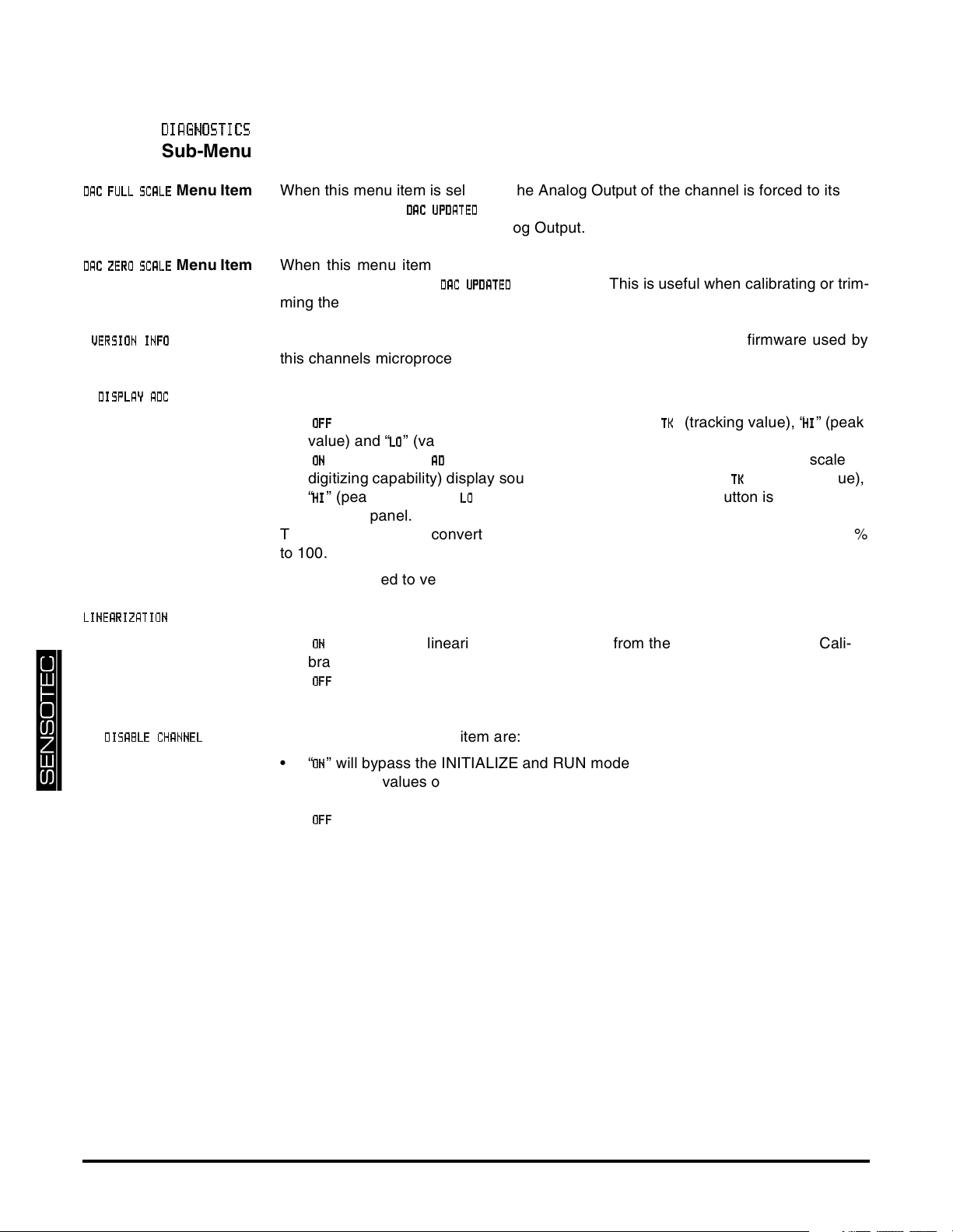
Menu Item When this menu item is selected, the Analog Output of the channel is forced to its full-
scale output, then
DDDDAAAACCCCUUUUPPPPDDDDAAAATTTTEEEEDDDD
is displayed. This is useful when calibrating or trimming
the readout connected to the Analog Output.
Menu Item When this menu item is selected, the Analog Output of the channel is forced to its
zero-scale output, then
DDDDAAAAC UP
CUPDDDDAAAATTTTEEEEDDDD
CUPCUP
is displayed. This is useful when calibrating or trim-
ming the readout connected to the Analog Output.
Menu Item This menu item displays the part number and revision level of the firmware used by
this channels microprocessor.
Menu Item The options for this menu item are:
•“
•“
” will allow the [VALUE] button to cycle through “
OOOOFFFFFFFF
value) and “
” will allow the “
OOOONNNN
” (valley value). This is the recommended option.
LLLLOOOO
” (percentage of the Analog-to-Digital converter’s full-scale
AAAADDDD
” (tracking value), “
TTTTKKKK
digitizing capability) display source to be available along with “
“
” (peak value) and “
HHHHIIII
” (valley value) when the [VALUE] button is pressed on
LLLLOOOO
” (peak
HHHHIIII
” (tracking value),
TTTTKKKK
the front panel.
The Analog-to-Digital converter counts are displayed as a percentage from -100.00%
to 100.00%.
This can be used to verify the correct operation of the input circuitry of the channel.
Menu Item The options for this menu item are:
•“
” will allow the linearization data obtained from the 5-Point Known Load Cali-
OOOONNNN
bration to affect a channel’s scaled values. This is the recommended option.
•“
” will not allow linearization data to effect the channel’s scaled values. This is
OOOOFFFFFFFF
useful when diagnosing problems in a calibration procedure.
DDDDIIIISSSSAAAABBBBLLLLEEEECCCCHHHHAAAANNNNNNNNEEEELLLL
Menu
Item
page 20 008-0608-01
The options for this menu item are:
•“
” will bypass the INITIALIZE and RUN modes of the channel. The track, peak
OOOONNNN
and valley values of the channel are forced to 0. This option is helpful when a
channel is installed but not being used.
•“
” will allow normal operation of the channel.
OOOOFFFFFFFF
Page 21
2.7 Analog Output Configuration
2.7.1 Identifying the Output Type
2.7.2 Channel Menu
Items
2.7.3 Output Selection
A RTD Input channel is available with one of two types of digital-to-analog (DAC)
outputs: voltage or current. You can determine which type of output a channel
has by one of three ways:
• Consulting the instrument’s Customer Information Sheet
• Examining the
SSSSYYYYSSSSTTTTEEEEMMMM MEN
nn is the number of the channel. If the channel’s type is
age output. If the channel’s type is
MENUUUU
MENMEN
->
CCCCOOOONNNNFFFFIIIIGGGGUUUURRRRAAAATTTTIIIIOOOONNNN
RRRRTTTTDDDDIo
Iout
IoIo
->
, it has a current output.
ut
utut
CCCCHHHHAAAANNNNNNNNEEEELLLL
nn
menu item where
TTTTYYYYPPPPEEEE
RRRRTTTTDDDDVVVVoooouuuutttt
, it has a volt-
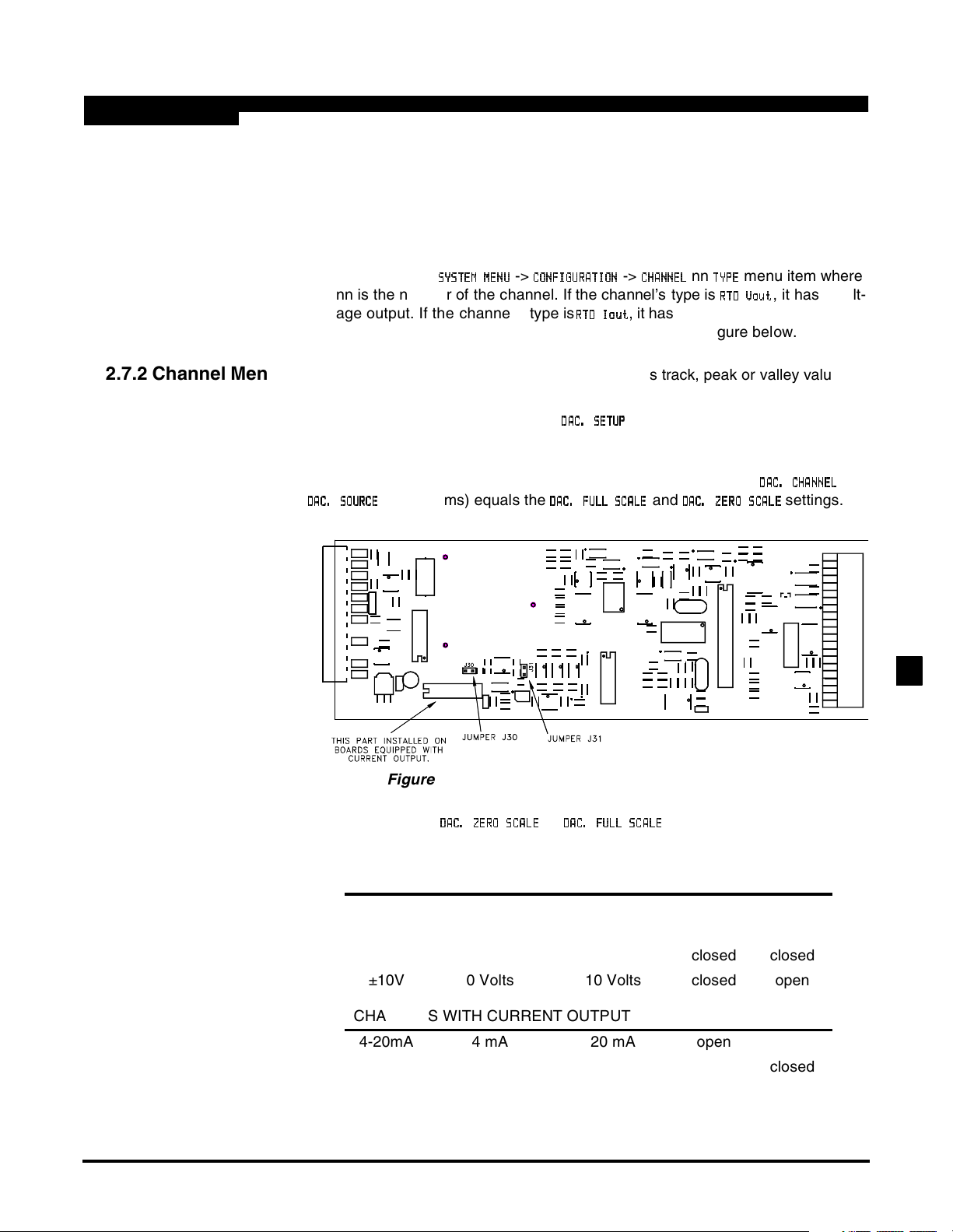
• Examining the channel’s circuit board as shown in the figure below.
The Analog Output can be driven by any channel’s track, peak or valley value.
See the “Channel Menu” section earlier in this chapter for a complete listing of
SETUP menu items available on the
DDDDAAAACCCC.... SETU
sub-menu.
SETUPPPP
SETUSETU
Jumpers located on the channel’s circuit board determine what outputs are generated when the value selected to drive the Analog Output (from the
DDDDAAAACCCC.... SOURC
SOURCEEEE
SOURCSOURC
menu items) equals the
DA
DACCCC.... FULL S
FULL SCCCCAL
DADA
FULL SFULL S
ALEEEE
ALAL
and
DDDDAAAACCCC.... ZERO S
ZERO SCCCCAAAALLLLEEEE
ZERO SZERO S
DDDDAAAACCCC. CH
.CHAAAANNNNNNNNEEEELLLL
.CH.CH
settings.
and
Figure 2-4: Digital-to-Analog Output Jumper Locations
DDDDAAAACCCC....ZZZZEEEERRRROOOO SCAL
Output
SCALEEEE
SCALSCAL
DDDDAAAACCCC....FFFFUUUULLLLLLLL SCAL
SCALEEEE
SCALSCAL
Output
J30
jumper
J31
jumper
CHANNELS WITH VOLTAGE OUPUT
0-5V 2.5 Volts 5 Volts open closed
±5V 0 Volts 5 Volts open open
0-10V 5 Volts 10 Volts closed closed
±10V 0 Volts 10 Volts closed open
CHANNELS WITH CURRENT OUTPUT
4-20mA 4 mA 20 mA open open
4-20mA 12 mA 20 mA open closed
RTD INPUT CHANNEL2
Additional Channels for SC Series Instrumentation page 21
Page 22
2.8 Troubleshooting
2.8.1 Error Messages
See the “Error Messages” chapter of the “SC Series Instruction Manual”, Sensotec p/
n 008-0608-00, for information relating to error messages.
2.8.2 Common
Problems and
Solutions
Erratic Display Make sure that the temperature on the RTD is constant. A RTD simulator/calibrator
may be used.
The RTD Input channel is calibrated at the factory for Pt100 RTD’s with the DIN stan-
dard output curve. See “Channel Specifications” on pag e13.
It is recommended that the RTD Input channel be calibrated at -200ºC, -100ºC, 0ºC,
+100ºC and +200ºC for rated accuracy.
+OVLD or -OVLD on
Display
Analog Output
Incorrect
Check “Wiring” on page 10 and make certain that nothing is connected to the pins
labeled as “N/C”.
The RTD Input channel is calibrated at the factory for Pt100 RTD’s with the DIN stan-
dard output curve. See “Channel Specifications” on pag e13.
Make certain of the type of Analog Output (voltage or current) that the channel is
equipped with; see “Identifying the Output Type” on page21.
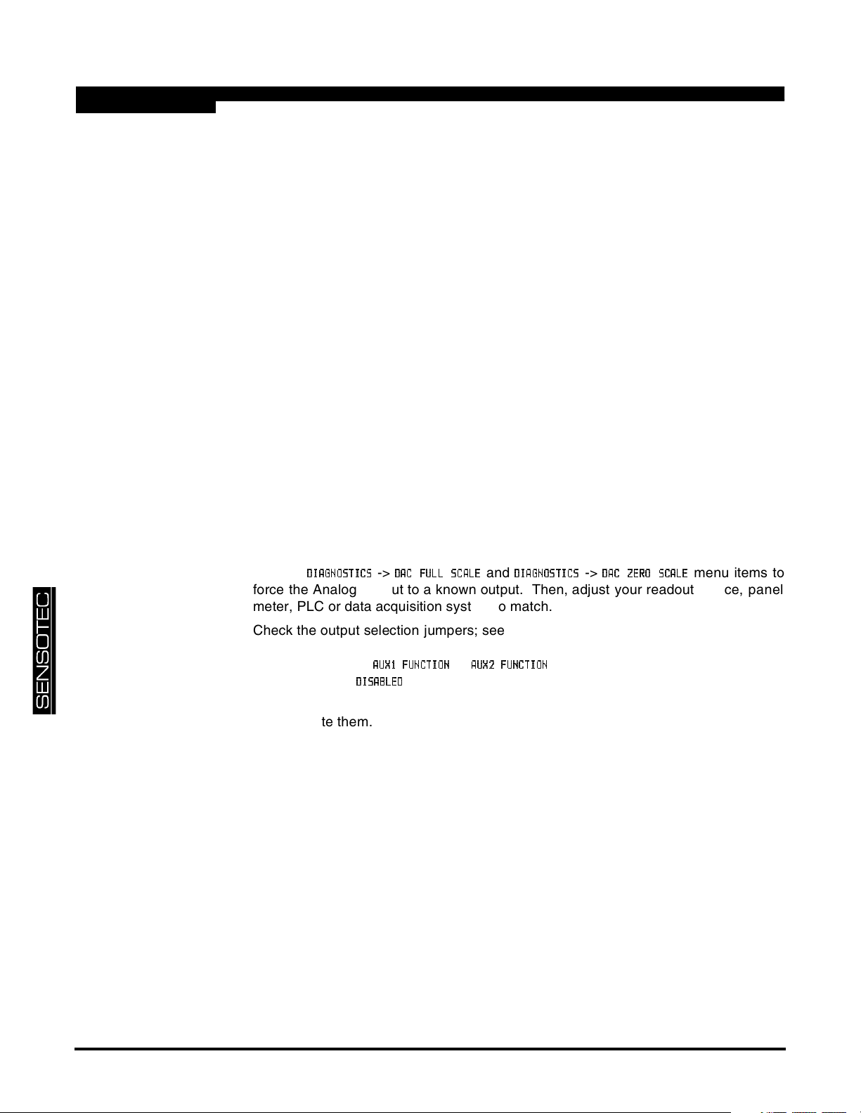
Use the
DDDDIIIIAAAAGGGGNO
NOSSSSTTTTIIIICCCCSSSS
NONO
->
DDDDAC
AC FFFFUL
ACAC
ULLLLLSC
SCAAAALLLLEEEE
ULUL
SCSC
and
DDDDIIIIAAAAGGGGNNNNOOOOSSSSTTTTIIIICCCCSSSS
->
DDDDAAAAC Z
CZEEEERRRRO S
CZCZ
OSCCCCAAAALLLLEEEE
OSOS
menu items to
force the Analog Output to a known output. Then, adjust your readout device, panel
meter, PLC or data acquisition system to match.
Auxiliary Function
Pins Not Operating
Check the output selection jumpers; see “Output Selection” on page 21.
Make sure that the
if they are set to
DDDDIIIISSSSAAAABBBBLLLLEEEEDDDD
AAAAUX
UX1111FFFFUUUUNNNNCCCCTTTTIIIIOOOONNNN
UXUX
then they will not operate.
or
AAAAUUUUXXXX2 F
2FUUUUNNNNCCCCTTTTIIIIOOOONNNN
2F2F
SETUP menu items are set correctly;
The Auxiliary Function (“AUX1” and “AUX2”) pins must be connected to pin 10, not pin
8, to activate them.
page 22 008-0608-01
Page 23
2.9 Communication Commands
2.9.1 Introduction
2.9.2 Descriptions
This section only documents the communication commands that affect the operation
of the RTD Input channel. Refer to document p/n 008-0610-00, “SC Series Communications Guide” for details regarding serial communications. This document can be
downloaded from Sensotec’s web site, www.sensotec.com.
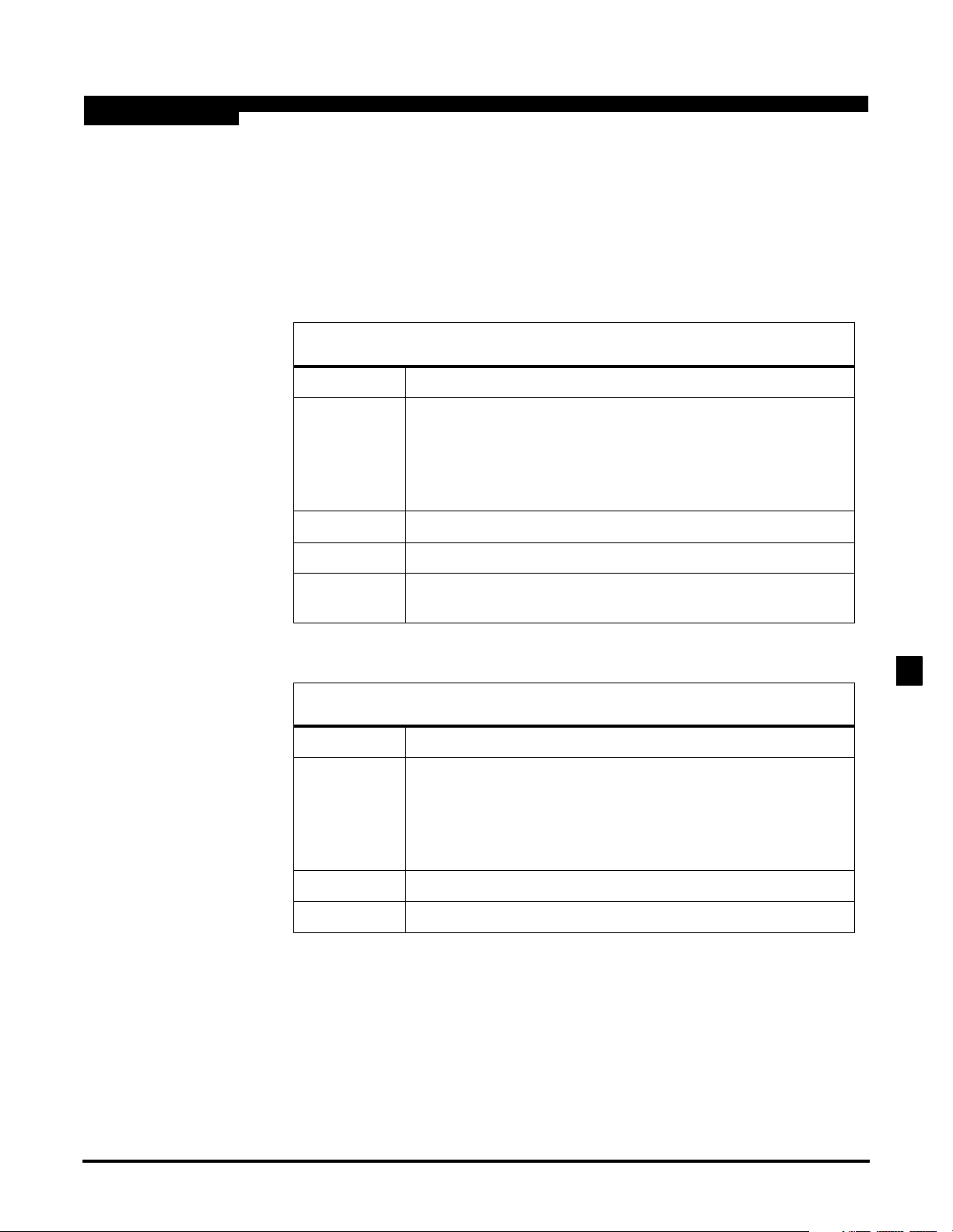
F0 Transmit Track Data
Purpose To transmit the channel’s tracking data value
Usage "
Example "
Reply "
Remarks The input channel continuously reads the RTD. This function
aacc
#
#
is the ‘pound’ or ‘hash’ character (ASCII decimal 35).
aa
is the two-character instrument address.
cc
is the two-character channel number
↵ is the ‘carriage return’ character (ASCII decimal 13).
#0001F0
0037.5
transmits the most recent reading.
↵"
F0
↵"
” (typical)
F9 Transmit Peak Data
Purpose To transmit the channel’s peak data value
Usage "
Example "
Reply "
aacc
#
#
is the ‘pound’ or ‘hash’ character (ASCII decimal 35).
aa
is the two-character instrument address.
cc
is the two-character channel number
↵ is the ‘carriage return’ character (ASCII decimal 13).
#0001F9
0162.5
↵"
F9
↵"
” (typical) or "
N/A
”
RTD INPUT CHANNEL2
Additional Channels for SC Series Instrumentation page 23
Page 24
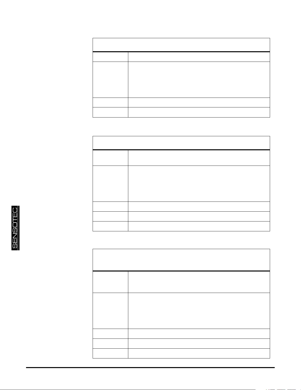
FA Transmit Valley Data
Purpose To transmit the channel’s valley data value
Usage "
Example "
Reply "
aacc
#
#
is the ‘pound’ or ‘hash’ character (ASCII decimal 35).
aa
is the two-character instrument address.
cc
is the two-character channel number
↵ is the ‘carriage return’ character (ASCII decimal 13).
#0001FA
-0012.5
↵"
FA
↵"
” (typical) or "
N/A
”
FB Clear Peak and Valley Data
Purpose To reset the channel’s peak and valley data values to the track
value.
Usage "
Example "
aacc
#
#
is the ‘pound’ or ‘hash’ character (ASCII decimal 35).
aa
is the two-character instrument address.
cc
is the two-character channel number
↵ is the ‘carriage return’ character (ASCII decimal 13).
#0001FB
FB
↵"
↵"
Reply "
Remarks This command is not available on the Model SC1000.
OK
” or "
N/A
”
FF Transmit Analog-to-Digital Converter
Reading
Purpose To transmit the Analog-to-Digital converter reading as a per-
centage from -100% to +100% of the A/D converters’s full
scale.
Usage "
Example "
Reply "
Remarks none
aacc
#
#
is the ‘pound’ or ‘hash’ character (ASCII decimal 35).
aa
is the two-character instrument address.
cc
is the two-character channel number
↵ is the ‘carriage return’ character (ASCII decimal 13).
#0001FF
50.000
↵"
FF
↵"
” (typical)
page 24 008-0608-01
Page 25
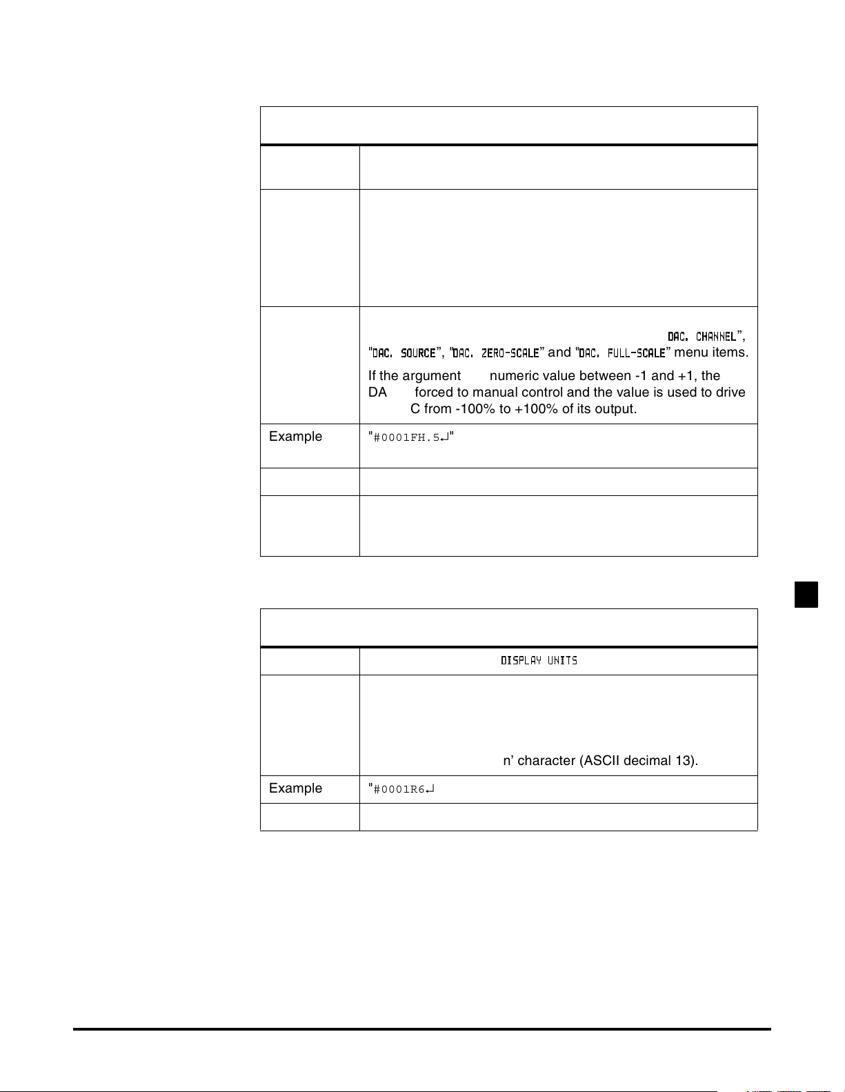
FH Write DAC Control Value
Purpose To control the channel’s Digital-to-Analog Converter (DAC)
manually or automatically.
Usage "
aaccFHn
#
#
is the ‘pound’ or ‘hash’ character (ASCII decimal 35).
aa
is the two-character instrument address.
cc
is the two-character channel number
n
is the argument defined below.
↵"
↵ is the ‘carriage return’ character (ASCII decimal 13).
Argument "
” returns the DAC to its normal automatic operation
AUTO
(power-on default). That is, it is controlled by the "
"
DDDDAAAACCCC. SO
.SOUUUURRRRCCCCEEEE
.SO.SO
”, "
DDDDAAAACCCC. Z
.ZEEEERRRROOOO----SSSSCCCCAAAALLLLEEEE
.Z.Z
” and "
DDDDAAAACCCC. F
.FUUUULLLLLLLL----SSSSCCCCAAAALLLLEEEE
.F.F
DDDDAAAACCCC....CCCCHHHHAAAANNNNNNNNEEEELLLL
”,
” menu items.
If the argument is a numeric value between -1 and +1, the
DAC is forced to manual control and the value is used to drive
the DAC from -100% to +100% of its output.
Example "
#0001FH.5
↵" will force channel 01’s DAC to +50% of full-
scale.
Reply "
OK
” or "
ERROR
”
Remarks You might wish to force a channel’s DAC to a certain output to
help calibrate the attached data acquisition system or other
device.
R6 Read Display Units
Purpose Reads the channel’s "
Usage "
aacc
#
#
is the ‘pound’ or ‘hash’ character (ASCII decimal 35).
aa
is the two-character instrument address.
cc
is the two-character channel number
↵" to read.
R6
DDDDIS
ISPPPPLLLLAAAAYYYY UNIT
ISIS
↵ is the ‘carriage return’ character (ASCII decimal 13).
Example "
#0001R6
↵”
Reply When reading: a four-character string.
” menu item
UNITSSSS
UNITUNIT
RTD INPUT CHANNEL2
Additional Channels for SC Series Instrumentation page 25
Page 26
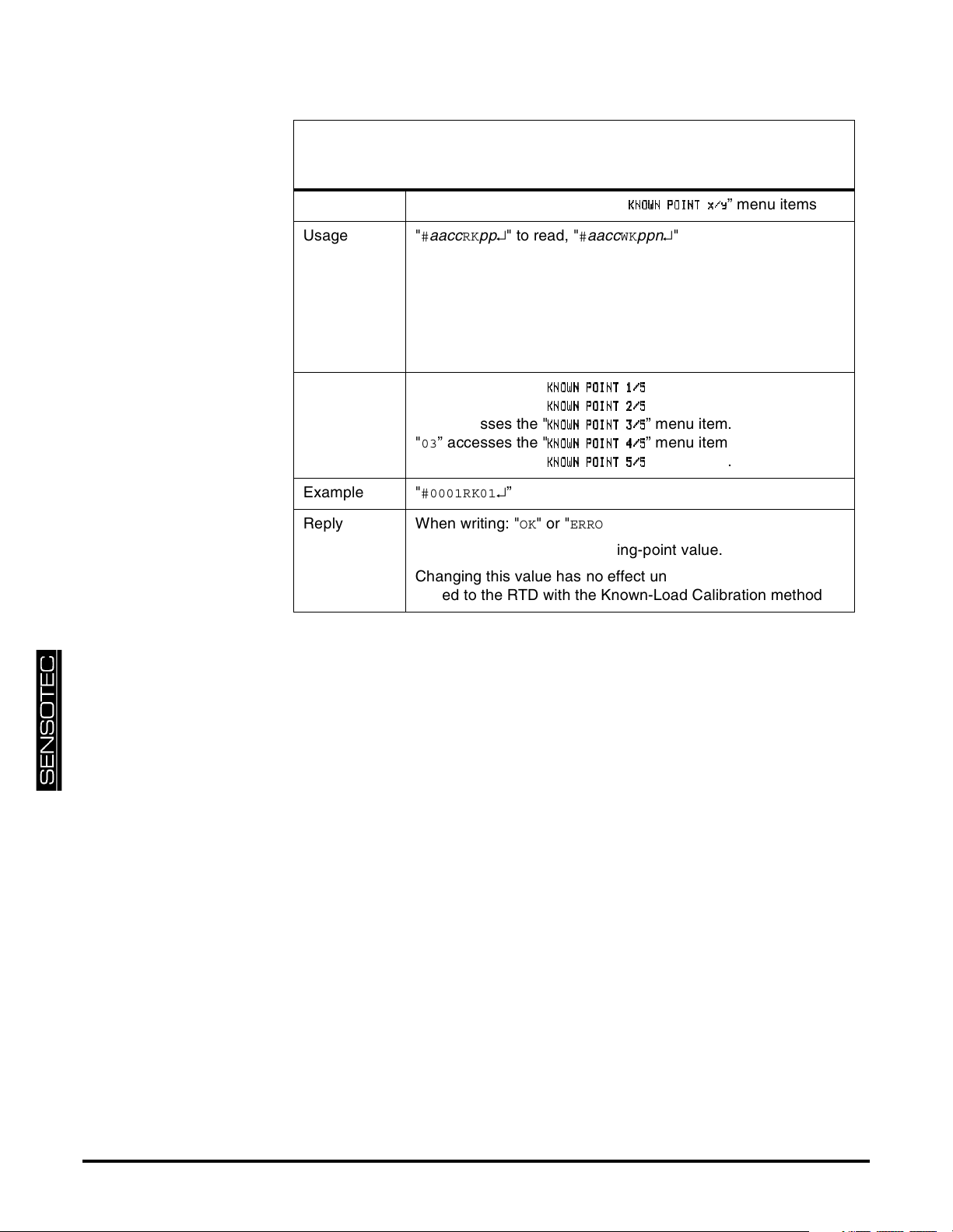
RK/WK Read/Write Known-Load Calibration
Point
Purpose Reads or writes the channel’s "
Usage "
aaccRKpp
#
#
is the ‘pound’ or ‘hash’ character (ASCII decimal 35).
aa
is the two-character instrument address.
cc
is the two-character channel number
pp
is the parameter defined below.
n
is the known-load calibration point in engineering units.
↵" to read, "
aaccWKppn
#
↵ is the ‘carriage return’ character (ASCII decimal 13).
Parameter "
Example "
Reply When writing: "OK
” accesses the "
00
"
” accesses the "
01
"
” accesses the "
02
"
” accesses the "
03
"
” accesses the "
04
#0001RK01
↵”
KKKKNNNNOOOOWWWWNNNN POINT 1
POINT 1////5555
POINT 1POINT 1
KKKKNNNNOOOOWWWWNNNN POINT 2
POINT 2////5555
POINT 2POINT 2
KKKKNNNNOOOOWWWWNNNN POINT 3
POINT 3////5555
POINT 3POINT 3
KKKKNNNNOOOOWWWWNNNN POINT 4
POINT 4////5555
POINT 4POINT 4
KKKKNNNNOOOOWWWWNNNN POINT 5
POINT 5////5555
POINT 5POINT 5
" or "
ERROR
”.
When reading: an ASCII-floating-point value.
Changing this value has no effect until the channel is re-calibrated to the RTD with the Known-Load Calibration method.
KKKKNNNNOOOOWWWWNNNN POINT x
POINT x////yyyy
POINT xPOINT x
↵" to write.
” menu item.
” menu item.
” menu item.
” menu item.
” menu item.
” menu items
page 26 008-0608-01
Page 27
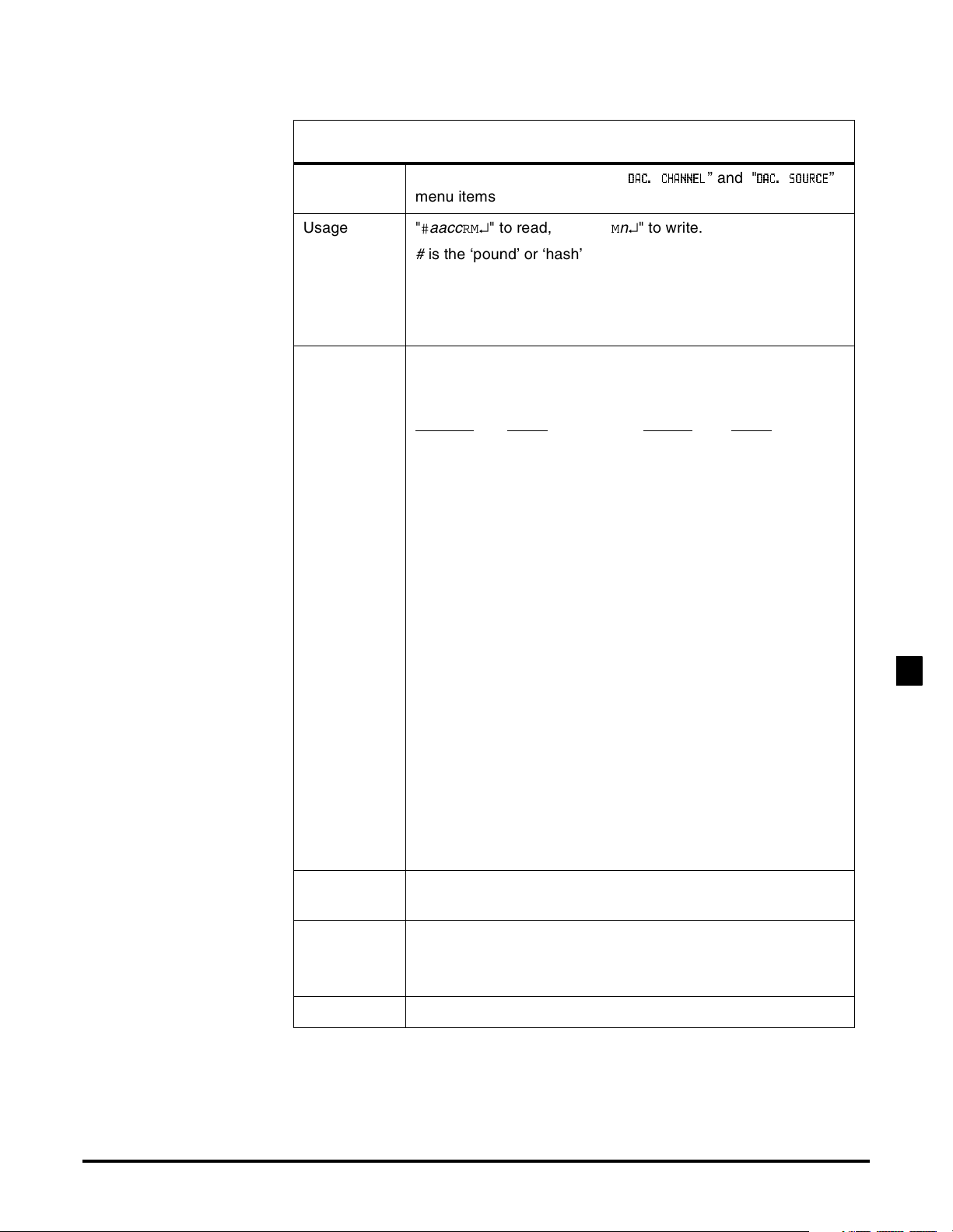
RM/WM Read/Write DAC Channel & Value
Purpose Reads or writes the channel’s "
DDDDAAAACCCC.... CHANNE
CHANNELLLL
CHANNECHANNE
” and "
DDDDAC
AC.... SOURC
SOURCEEEE
ACAC
SOURCSOURC
menu items
Usage "
aacc
#
#
is the ‘pound’ or ‘hash’ character (ASCII decimal 35).
aa
is the two-character instrument address.
cc
is the two-character channel number.
n
is the argument defined below.
↵" to read, "
RM
aaccWMn
#
↵" to write.
↵ is the ‘carriage return’ character (ASCII decimal 13).
Argument A number which selects a channel’s value. This number is
created by adding together the values of the desired options
as shown.
Channel
Value Source Value
01 1. TRACK 0.
02 2. PEAK 16.
03 3. VALLEY 32.
04 4.
05 5.
06 6.
07 7.
08 8.
09 9.
10 10.
11 11.
12 12.
13 13.
14 14.
15 15.
16 64.
17 65.
18 66.
19 67.
20 68.
21 69.
22 70.
23 71.
”
RTD INPUT CHANNEL2
Example "
#0001RM33
↵" will cause the channel 01’s DAC to monitor
channel 01’s valley value.
Reply When writing: "
When reading: a number corresponding to a channel number
and data value as shown above.
Remarks none
Additional Channels for SC Series Instrumentation page 27
OK
", "
ERROR
” or "
N/A
”.
Page 28
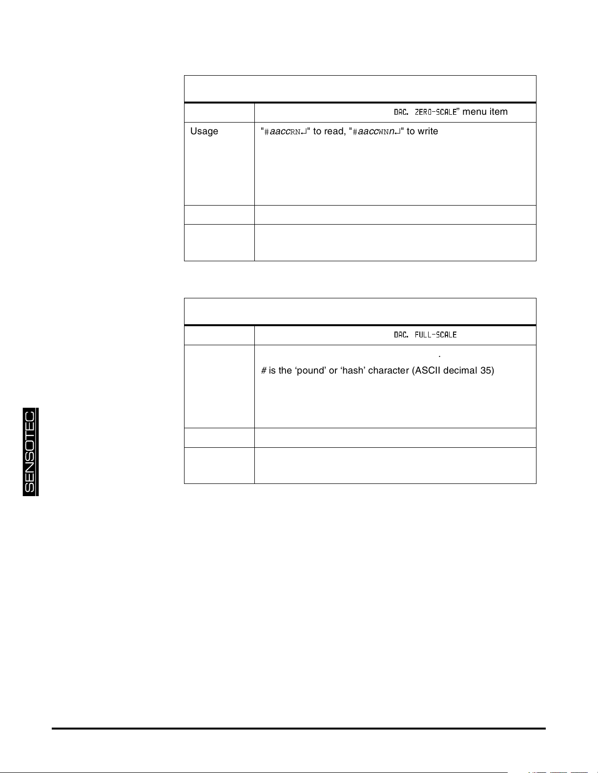
RN/WN Read/Write DAC Zero-Scale Value
Purpose Reads or writes the channel’s "
Usage "
aacc
#
#
is the ‘pound’ or ‘hash’ character (ASCII decimal 35).
aa
is the two-character instrument address.
cc
is the two-character channel number
n
is the zero Analog Output value in engineering units.
↵" to read, "
RN
aaccWNn
#
DDDDAAAACCCC.... ZERO-SCAL
ZERO-SCALEEEE
ZERO-SCALZERO-SCAL
↵" to write.
” menu item
↵ is the ‘carriage return’ character (ASCII decimal 13).
Example "
#0001WN-8000
Reply When writing: "
↵”
OK
" or "
ERROR
”.
When reading: an ASCII-floating-point value.
RO/WO Read/Write DAC Full-Scale Value
Purpose Reads or writes the channel’s "
Usage "
aacc
#
#
is the ‘pound’ or ‘hash’ character (ASCII decimal 35).
aa
is the two-character instrument address.
cc
is the two-character channel number
n
is the full Analog Output value in engineering units.
↵" to read, "
RO
aaccWOn
#
↵ is the ‘carriage return’ character (ASCII decimal 13).
DDDDAAAACCCC.... FULL-SCAL
FULL-SCALEEEE
FULL-SCALFULL-SCAL
↵" to write.
” menu item
Example "
#0001WO8000
Reply When writing: "
When reading: an ASCII-floating-point value.
↵”
OK
" or "
ERROR
”.
page 28 008-0608-01
Page 29
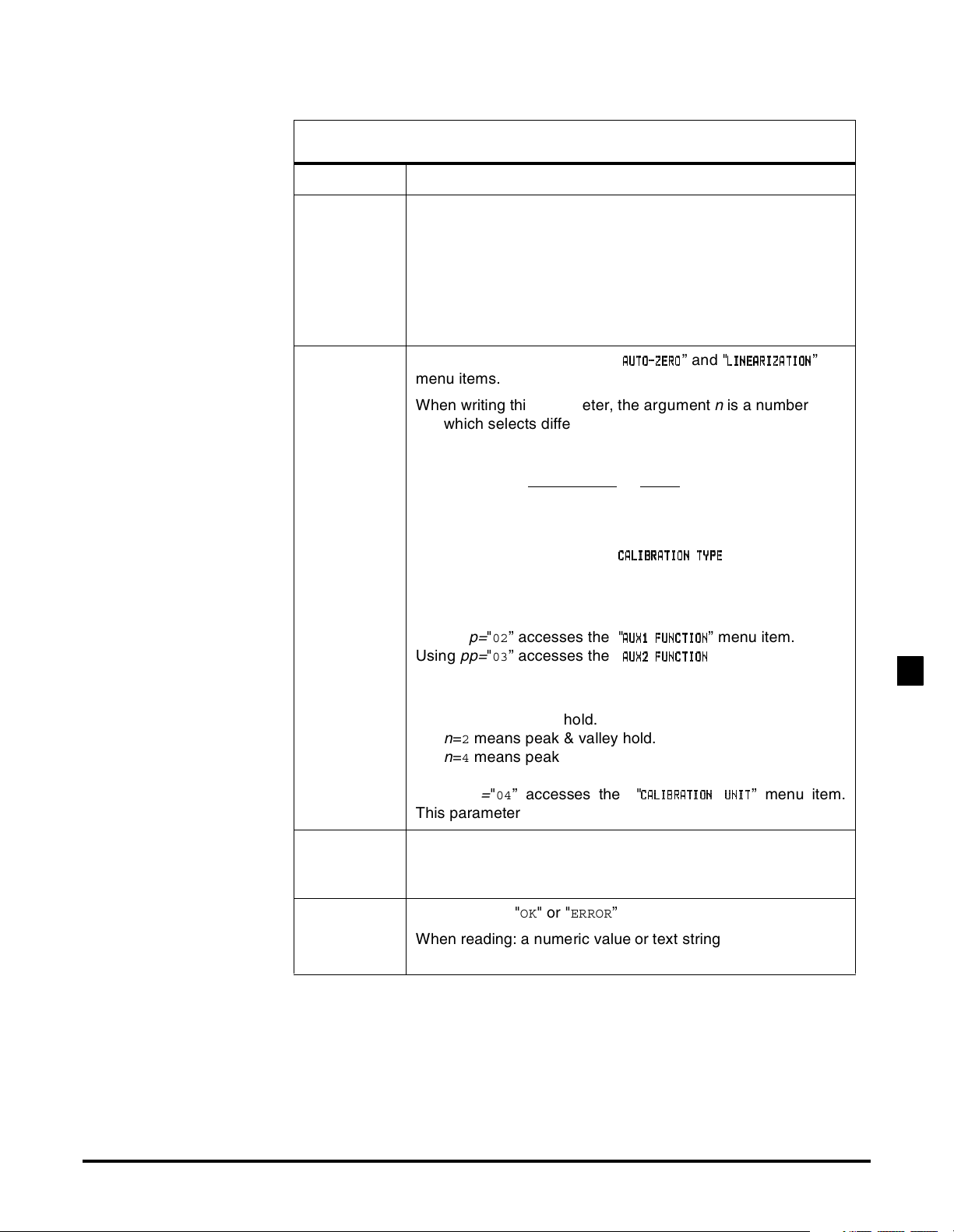
RP/WP Read/Write Operation
Purpose Read or write the operation settings of the channel
Usage "
Parameters
& Arguments
aaccRPpp
#
#
is the ‘pound’ or ‘hash’ character (ASCII decimal 35).
aa
is the two-character instrument address.
cc
is the two-character channel number.
pp
is one of the two-character parameters given below.
n
is the argument.
↵" to read, "
aaccWPppn
#
↵" to write.
↵ is the ‘carriage return’ character (ASCII decimal 13).
pp=
Using
"00” accesses the "
AAAAUUUUTTTTOOOO----ZZZZEEEERRRROOOO
” and "
LLLLIIIINNNNEEEEAAAARRRRIIIIZZZZAAAATTTTIIIIOOOONNNN
menu items.
When writing this parameter, the argument
n
is a number
which selects different operating features. This number is
created by adding together the values of the desired
options as shown.
Linearization
Value
OFF 0.
ON 16.
Using
pp=
"01” accesses the "
CCCCAAAALLLLIIIIBBBBRRRRAAAATTTTIIIIOOOONNNN TYP
” menu item.
TYPEEEE
TYPTYP
When reading this parameter:
n
=5 means 5-Point Known-Load Calibration.
Using
pp=
Using
"02” accesses the "
pp=
"03” accesses the "
AAAAUUUUXXXX1111 FUNCTIO
FUNCTIONNNN
FUNCTIOFUNCTIO
AAAAUUUUXXXX2222 FUNCTIO
FUNCTIONNNN
FUNCTIOFUNCTIO
” menu item.
” menu item.
When writing these parameters:
n
=0 means the Auxiliary Function pin is disabled.
n
=1 means track hold.
n
=2 means peak & valley hold.
n
=4 means peak & valley clear (edge triggered).
”
RTD INPUT CHANNEL2
Using
pp=
"04” accesses the "
This parameter can be read from, not written to.
Example Sending "
#0001WP0216
01’s Auxiliary 1 Function pin to activate the Tare function. The
instrument will reply with "
Reply When writing: "
When reading: a numeric value or text string according to the
information above.
Additional Channels for SC Series Instrumentation page 29
OK
CCCCAAAALLLLIIIIBBBBRRRRAAAATTTTIIIIOOOON U
NUNNNNIIIITTTT
NUNU
↵" will allow the assertion of channel
".
OK
" or "
ERROR
”
” menu item.
Page 30
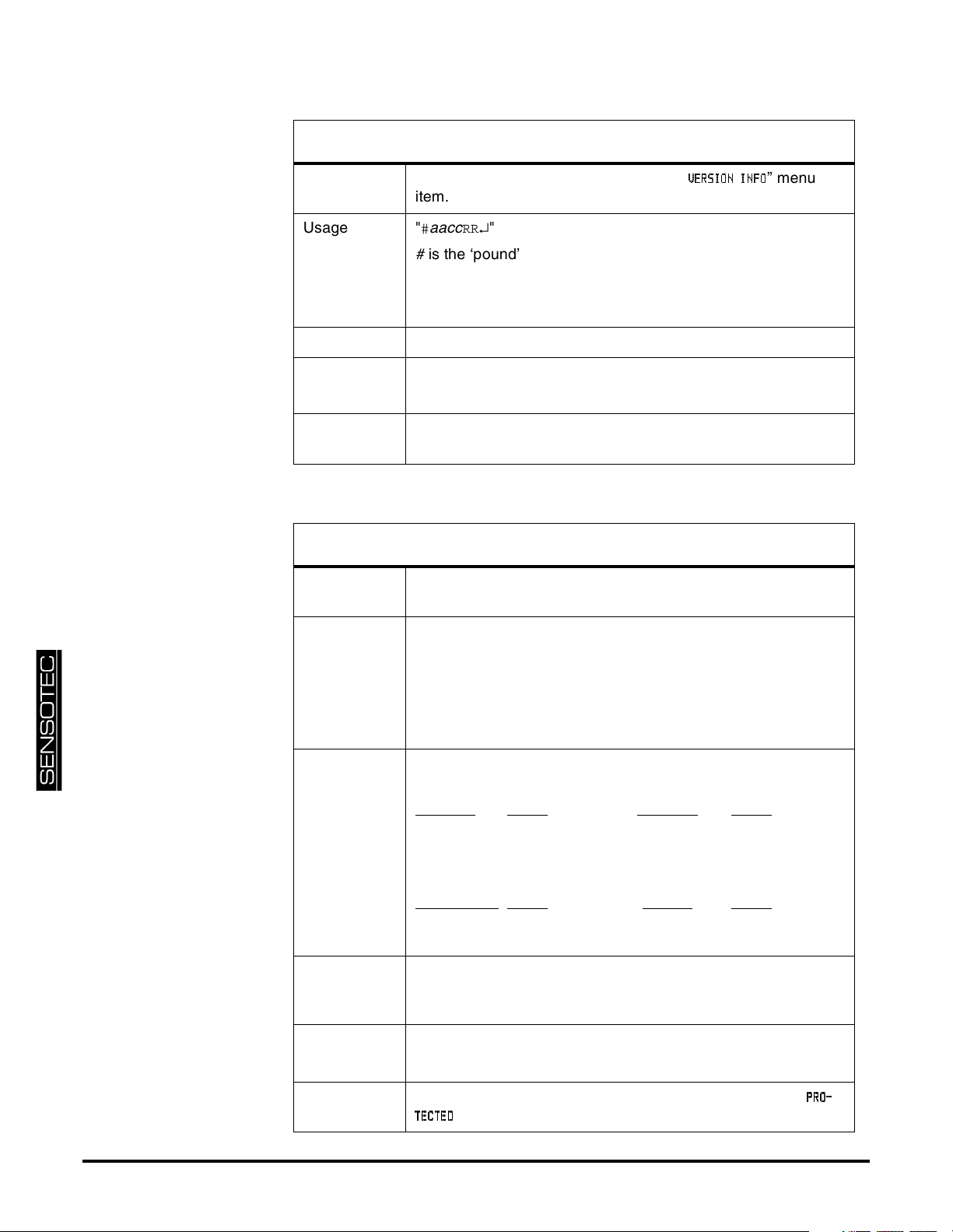
RR Read Version Info
Purpose Read version information found on the "
VVVVEEEERRRRSSSSIIIIOOOONNNN INF
INFOOOO
INFINF
” menu
item.
Usage "
aacc
#
#
is the ‘pound’ or ‘hash’ character (ASCII decimal 35).
aa
is the two-character instrument address.
cc
is the two-character channel number
RR
↵"
↵ is the ‘carriage return’ character (ASCII decimal 13).
Example "
#0001RR
↵"
Reply A text string such as
084-1169-01 04
Remarks This is the part number and version of the firmware used by
the channel’s microprocessor.
RT/WT Read/Write Front Panel Switch Operation
Purpose Reads or writes the operation of the front panel switches when
the Protection jumper is installed.
Usage "
aacc
#
#
is the ‘pound’ or ‘hash’ character (ASCII decimal 35).
aa
is the two-character instrument address.
cc
is the two-character channel number.
n
is the argument defined below.
↵" to read, "
RT
aaccWTn
#
↵" to write.
↵ is the ‘carriage return’ character (ASCII decimal 13).
Argument The argument is created by adding together the values of the
desired options as shown.
[VALUE]
Value [CLEAR] Value
ENABLED 0. ENABLED 0.
DISABLED 8. DISABLED 4.
[CHANNEL]
Value [TARE] Value
ENABLED 0. ENABLED 0.
DISABLED 2. DISABLED 1.
Example It is desired to disable the [TARE] button for channel 02 when
the Protection jumper is installed. Sending "
#0002WT1
↵" will
accomplish this.
Reply When writing: "
OK
" or "
ERROR
”.
When reading: an ASCII-floating-point value described above.
page 30 008-0608-01
Remarks If a disabled front panel button is pressed, the message "
” will appear on the display.
TTTTEEEECCCCTTTTEEEEDDDD
PPPPRRRROOOO----
Page 31

RTD INPUT CHANNEL2
Additional Channels for SC Series Instrumentation page 31
Page 32

page 32 008-0608-01
Page 33

3.1 Features
Chapter 3
Frequency Input Channel
The Frequency Input channel accepts square wave or sine wave input signals
from such transducers as magnetic pickups, devices with TTL outputs, or devices
with PNP or NPN transistor outputs. These signals are AC coupled into a zerocrossing detector, digitized, converted into engineering units, and placed into the
track, peak and valley data values of the channel. A 5V excitation is available in
case it is required by the device.
Setup and calibration of the channel is made at the factory. Re-calibration can be
made manually through the SETUP mode with the known-load calibration method
and a customer-supplied frequency calibrator.
The engineering units used to display the frequency are Hz. A Mathematics Virtual channel can be factory programmed for specific applications that required
conversion into units of RPM or horsepower.
Two rear panel control inputs can be field-configured for such functions as remote
track/hold, disabling peak/valley detection and clearing the peak/valley values. A
voltage or current digital-to-analog output is also provided.
3.2 Getting Started Quickly
As shipped from the factory, the Frequency Input channel is calibrated and ready
for use.
Connect the output of your transdcuer to the Frequency Input channel according
to “Wiring” on pag e34.
FREQUENCY INPUT CHANNEL3
Additional Channels for SC Series Instrumentation page 33
Page 34
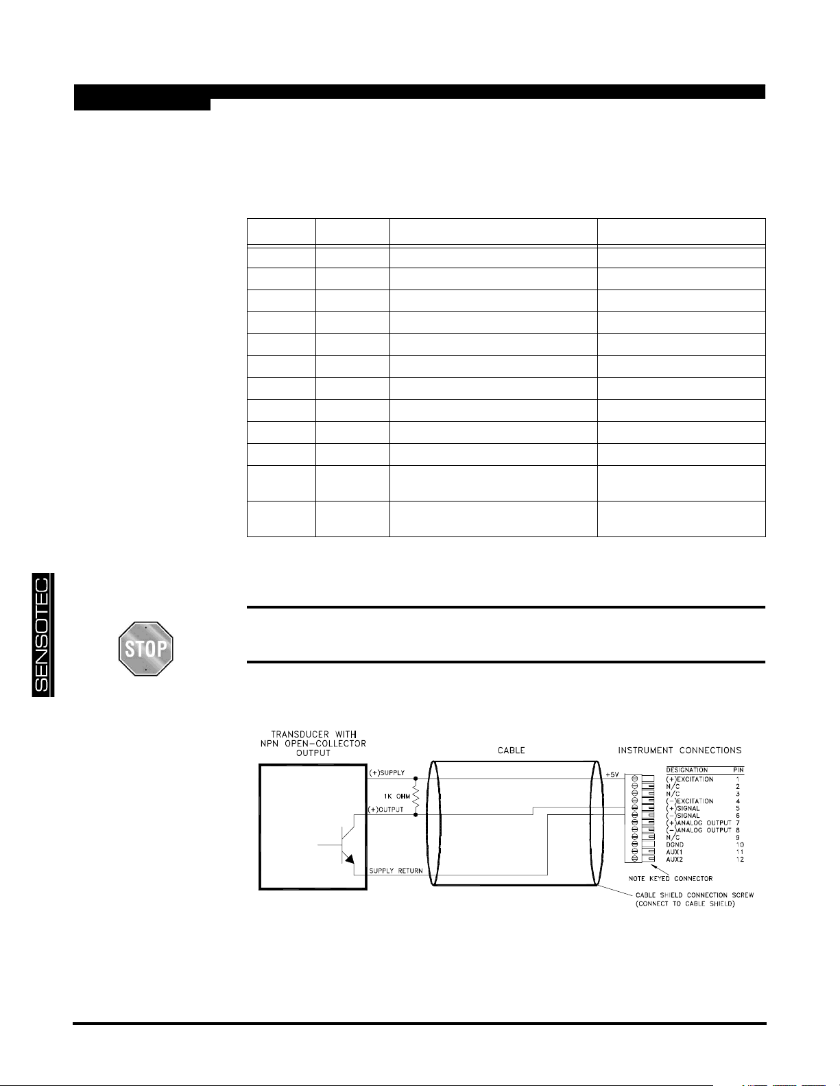
3.3 Wiring
3.3.1 Channel Connector
The pin-out for the channel’s connector is shown in the following table.
Table 3-1: Frequency Input Channel Pin Connections
Pin Label Function NOTES
1 (top) +EXC (+)Excitation referenced to pin 10
2N/C N/C DO NOT CONNECT!
3N/C N/C DO NOT CONNECT!
4 -EXC (-)Excitation referenced to pin 10
5 +SIG (+)Signal referenced to pin 10
6 -SIG (-)Signal referenced to pin 10
7 +OUT Analog Output referenced to pin 8
8 -OUT Analog Return -
9N/C N/C DO NOT CONNECT!
10 DGND Digital Ground -
11 AUX1 Auxiliary Function 1
(connect to pin 10 to activate)
12
(bottom)
The Analog Output and Analog Return pins are electrically isolated from all other pins
on the instrument.
AUX2 Auxiliary Function 2
(connect to pin 10 to activate)
referenced to pin 10
referenced to pin 10
3.3.2 NPN OpenCollector
Connection
Do not connect anything to the pins labeled as “N/C”. Damage to the instru-
ment or loss of accuracy may result.
.
Figure 3-1: NPN Open-Collector Connection to Frequency Input Channel
page 34 008-0608-01
Page 35
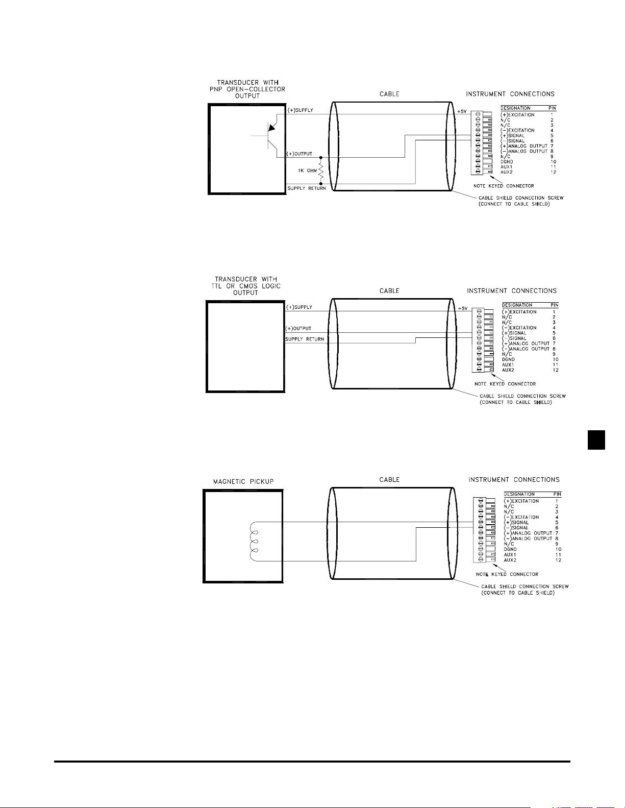
3.3.3 PNP OpenCollector
3.3.4 TTL/CMOS Logic Connection
Figure 3-2: PNP Open-Collector Connection to Frequency Input Channel
3.3.5 Magnetic Pickup Connection
Figure 3-3: TTL or CMOS Logic Connection to Frequency Input Channel
FREQUENCY INPUT CHANNEL3
Figure 3-4: Magnetic Pickup Connection to Frequency Input Channel
Additional Channels for SC Series Instrumentation page 35
Page 36
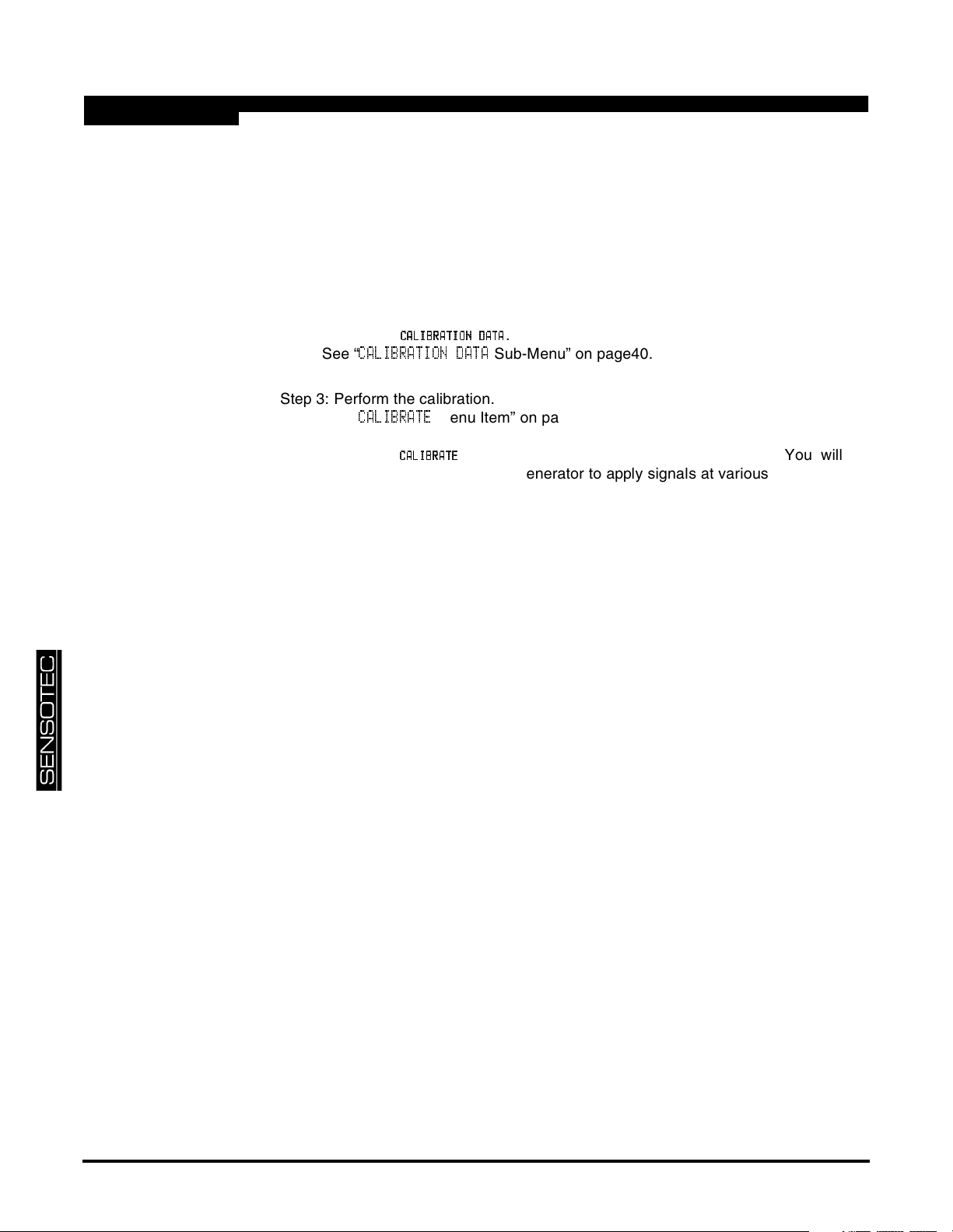
3.4 Calibration
A listing of all menu items for this channel is given in “Setup Menu Reference” on
page 55.
A customer-supplied signal generator is required for re-calibration. It should be set up
to produce a square wave output at 1V peak-to-peak amplitude.
Step 1: Wire the signal generator to the channel’s connector.
See “Wiring” on page 34.
Step 2: Enter the
See “
CALIBRATION DATA
CCCCAAAALLLLIB
IBRRRRAAAATTTTIIIIOOOONNNN DAT
IBIB
.
DATAAAA
DATDAT
Sub-Menu” on page40.
Step 3: Perform the calibration.
See “
CALIBRATE
Using the
Menu Item” on page 40.
CCCCAAAALLLLIIIIBBBBRRRRAAAATTTTEEEE
menu item starts the calibration process. You will be
prompted to use your signal generator to apply signals at various frequencies to
the channel as required.
page 36 008-0608-01
Page 37

3.5 Channel Specifications
FREQUENCY INPUT
Frequency Range 15 Hz to 40kHz (square wave)
200Hz to 40kHz (sine wave)
Threshold Zero Crossing (AC coupled)
Level 0.2Vpp to 30Vpp
Minimum Pulse Width 20us
Non-linearity 0.05% ful-scale
Temperature Effect 150 ppm/ºC
Frequency Response 2 Hz
Step Response 40 ms (typical)
EXCITATION OUTPUT
Output 5V @ 100mA max.
AUXILLIARY INPUTS
Quantity 2
Type momentary contact closure
Response Time < 5ms
Field-Selectable Functions peak/valley clear, peak/valley hold,
ANALOG OUTPUT
Output voltage range 5, ±5, 10 or ±10 VDC (field selectable)
Output current range (optional current
output channels)
Source any channel’s track, peak or valley value
Isolation 500V
Resolution 13 bits
Frequency Response same as input when driven by the same
track hold
FREQUENCY INPUT CHANNEL3
4-20 mA
channel’s tracking data
Additional Channels for SC Series Instrumentation page 37
Page 38
3.6 Channel Menu
The Frequency Input channel is configured and calibrated via its channel menu.
Detailed instructions on operating the instrument in the SETUP Menu mode can be
found in the “SC Series Instruction Manual”, Sensotec p/n 008-0608-00.
3.6.1
Sub-Menu
PPPPOOOOWWWWEEEERRRR----OOOONNNN SOURC
3.6.2
SOURCEEEE
SOURCSOURC
AUXn F
AUXn FUUUUNCTION
AUXn FAUXn F
Menu Items
OP
OPEEEERATION
RATION
OPOP
RATIONRATION
Menu
Item
NCTION
NCTIONNCTION
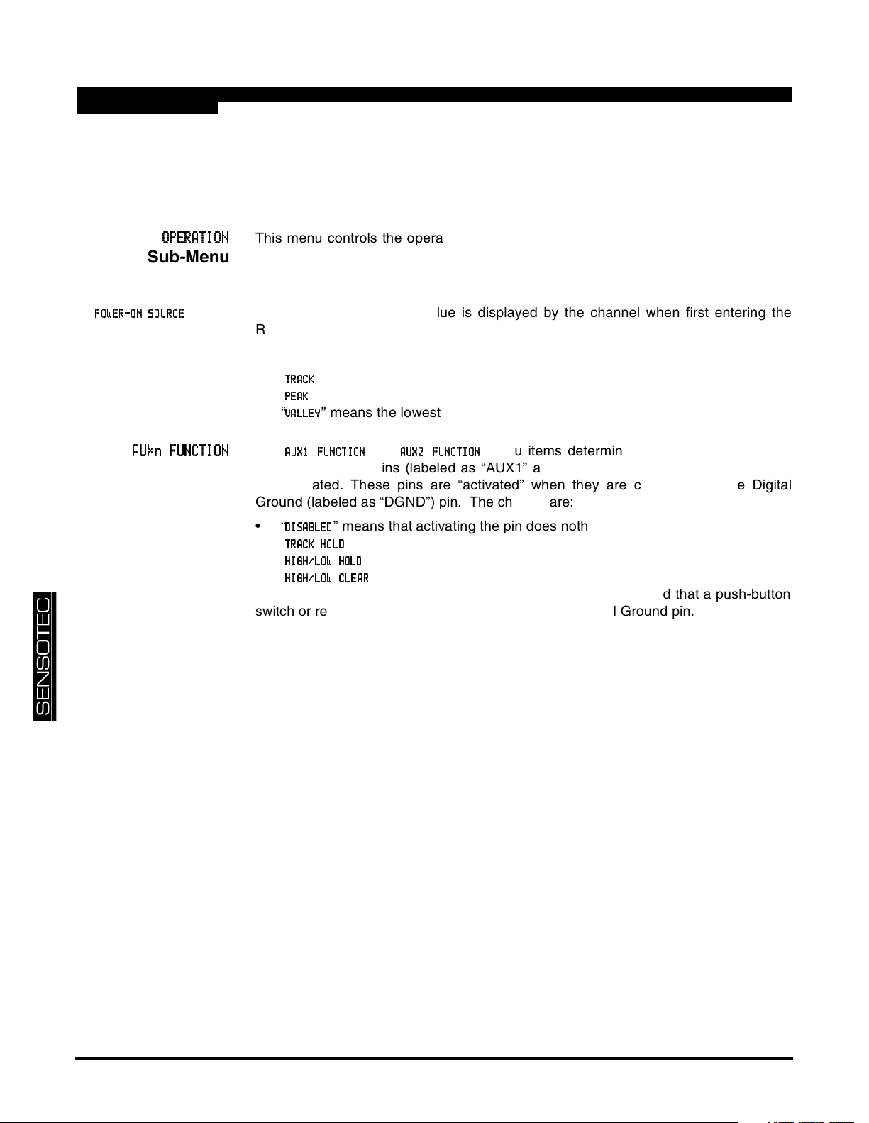
This menu controls the operation of this channel when the instrument is in the RUN
mode.
This menu selects which value is displayed by the channel when first entering the
RUN mode.
The choices are:
•“
•“
•“
The
” means the live tracking value of the channel.
TTTTRRRRAAAACCCCKKKK
” means the highest value of the channel.
PPPPEEEEAAAAKKKK
” means the lowest value of the channel.
VVVVAAAALLLLLLLLEEEEYYYY
AAAAUUUUXXXX1 F
1 FUN
1F1F
UNCCCCTTTTIIIIOOOONNNN
UNUN
and
AAAAUUUUXXXX2 F
2FUUUUNNNNCCCCTTTTIIIIOOOONNNN
2F2F
menu items determine what happens when the
Auxiliary Function pins (labeled as “AUX1” and “AUX2”) on the channel’s connector
are activated. These pins are “activated” when they are connected to the Digital
Ground (labeled as “DGND”) pin. The choices are:
•“
DDDDIIIISSSSAAAABBBBLLLLEEEEDDDD
•“
TTTTRRRRAAAACCCCKKKK HOL
•“
HHHHIIIIGGGGHHHH////LLLLOOOOWWWW HOL
•“
HHHHIIIIGGGGHHHH////LLLLOOOOWWWW CLEA
” means that activating the pin does nothing.
” means that the tracking, peak and valley values will not be updated.
HOLDDDD
HOLHOL
” means that the peak and valley values will not be updated.
HOLDDDD
HOLHOL
” means that the peak and valley values are reset.
CLEARRRR
CLEACLEA
As the Auxiliary Function pins are not isolated, it is recommended that a push-button
switch or relay is used to connect these pins to the Digital Ground pin.
page 38 008-0608-01
Page 39
3.6.3
CCCCALIBRATI
ALIBRATIOOOON TYPE
ALIBRATIALIBRATI
N TYPE
N TYPEN TYPE
Menu Item
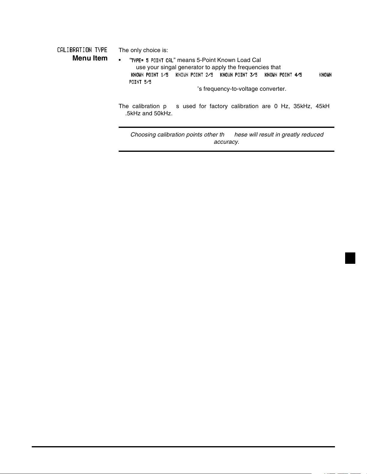
The only choice is:
•“
TTTTYYYYPPPPEEEE= 5
=5PPPPOOOOIIIINNNNT C
=5=5
” means 5-Point Known Load Calibration. You are prompted
TCAAAALLLL
TCTC
to use your singal generator to apply the frequencies that were entered in the
“
KKKKNNNNOOOOWWWWN PO
NPOIIIINNNNTTTT1111////5555
NPONPO
PPPPOOOOIIIINNNNTTTT5/
5/5555
5/5/
”, “
KKKKNNNNOOOOWWWWN P
NPOOOOIIIINNNNTTTT2222////5555
NPNP
”, “
KKKKNNNNOOOOWWWWNNNNPPPPOOOOIIIINNNNT 3/
T3/5555
T3/T3/
”, “
KKKKNNNNOOOOWN
WN PPPPOOOOIIIINNNNT 4/
T4/5555
WNWN
T4/T4/
” and “
KKKKNNNNOOOOWWWWNNNN
” registers. This technique is used to compensate for the non-linear-
ity inherent in the channel’s frequency-to-voltage converter.
The calibration points used for factory calibration are 0 Hz, 35kHz, 45kHz,
47.5kHz and 50kHz.
Choosing calibration points other than these will result in greatly reduced
accuracy.
FREQUENCY INPUT CHANNEL3
Additional Channels for SC Series Instrumentation page 39
Page 40
3.6.4
DA
DATTTTAAAA
DADA
CALI
CALIBBBBRATION
RATION
CALICALI
RATIONRATION
Sub-Menu
KKKKNNNNOOOOWWWWNNNN POINT x/
POINT x/yyyy
POINT x/POINT x/
3.6.5
CA
CALLLLIBRATE
CACA
Menu Item
Menu
Items
IBRATE
IBRATEIBRATE
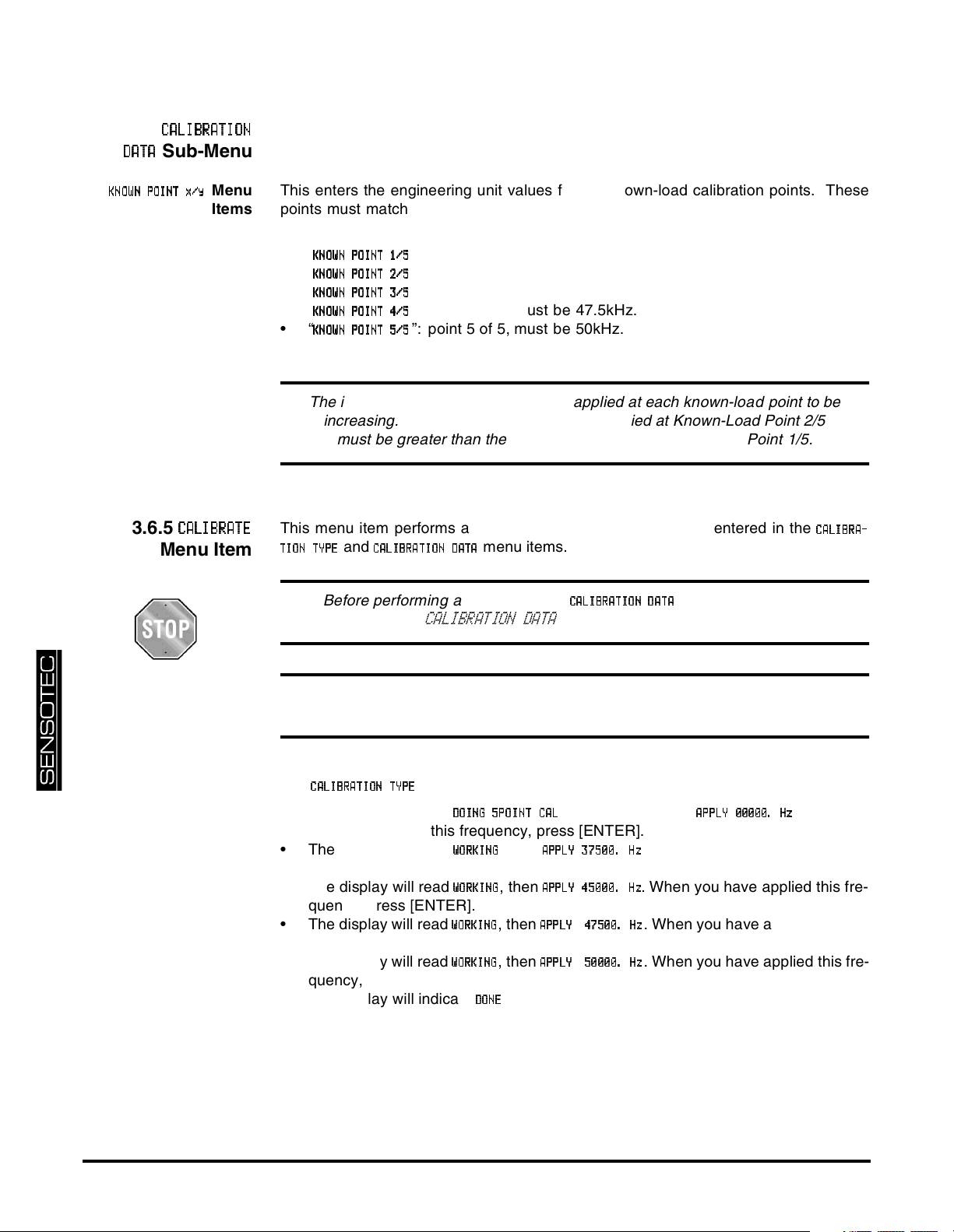
This enters the engineering unit values for the known-load calibration points. These
points must match the actual frequencies that you will apply to the instrument during
calibration. The following menu items are available:
•“
KKKKNNNNOOOOWWWWNNNN POINT 1/
•“
KKKKNNNNOOOOWWWWNNNN POINT 2/
•“
KKKKNNNNOOOOWWWWNNNN POINT 3/
•“
KKKKNNNNOOOOWWWWNNNN POINT 4/
•“
KKKKNNNNOOOOWWWWNNNN POINT 5/
POINT 1/5555
POINT 1/POINT 1/
POINT 2/5555
POINT 2/POINT 2/
POINT 3/5555
POINT 3/POINT 3/
POINT 4/5555
POINT 4/POINT 4/
POINT 5/5555
POINT 5/POINT 5/
”: point 1 of 5, must be 0Hz.
”: point 2 of 5, must be 35kHz.
”: point 3 of 5, must be 45kHz.
”: point 4 of 5, must be 47.5kHz.
”: point 5 of 5, must be 50kHz.
The instrument expects the frequency applied at each known-load point to be
increasing. For example, the frequency applied at Known-Load Point 2/5
must be greater than the frequency applied at Known-Load Point 1/5.
This menu item performs a calibration according to what was entered in the
and
TTTTIIIIOOOONNNN TYP
TYPEEEE
TYPTYP
CCCCAAAALLLLIIIIBBBBRRRRAAAATTTTIIIIOOOONNNN DAT
Before performing a calibration, the
“
CALIBRATION DATA
menu items.
DATAAAA
DATDAT
CCCCAAAALLLLIIIIBBBBRRRRAAAATTTTIIIIOOOONNNN DAT
must be entered (see
DATAAAA
DATDAT
Sub-Menu” on page40).
CCCCAAAALLLLIIIIBBBBRRRRAAAA----
For maximum accuracy, allow at least five minutes of warm-up before calibra-
tion.
The
CCCCAAAALLLLIIIIBBBBRRRRAAAATTTTIIIIOOOONNNN TYP
• The display will read
is 5-Point Known Load Calibration.
TYPEEEE
TYPTYP
DDDDOOOOIIIINNNNGGGG 5POINT C
5POINT CAAAALLLL
5POINT C5POINT C
, and prompt you to
AAAAPPPPPPPPLLLLYYYY 00000. H
00000. Hzzzz
00000. H00000. H
you have applied this frequency, press [ENTER].
• The display will read
WWWWOOOORRRRKKKKIIIINNNNGGGG
, then
AAAAPPPPPPPPLLLLYYYY 37500. H
37500. Hzzzz
37500. H37500. H
. When you have applied this fre-
quency, press [ENTER].
• The display will read
WWWWOOOORRRRKKKKIIIINNNNGGGG
, then
AAAAPPPPPPPPLLLLYYYY 45000. H
45000. Hzzzz
45000. H45000. H
. When you have applied this fre-
quency, press [ENTER].
• The display will read
WWWWOOOORRRRKKKKIIIINNNNGGGG
, then
AAAAPPPPPPPPLLLLYYYY44447777555500000000....HHHHzzzz
. When you have applied this fre-
quency, press [ENTER].
• The display will read
WWWWOOOORRRRKKKKIIIINNNNGGGG
, then
AAAAPPPPPPPPLLLLYYYY55550000000000000000....HHHHzzzz
. When you have applied this fre-
quency, press [ENTER].
• The display will indicate
and the instrument will return to the RUN mode.
DDDDOOOONNNNEEEE
. When
page 40 008-0608-01
Page 41
3.6.6
DDDDAAAACCCC.... CHANNE
CHANNELLLL
CHANNECHANNE
DDDDAAAACCCC.... SOURC
SOURCEEEE
SOURCSOURC
DA
DACCCC SETUP
SETUP
DADA
SETUPSETUP
Sub-Menu
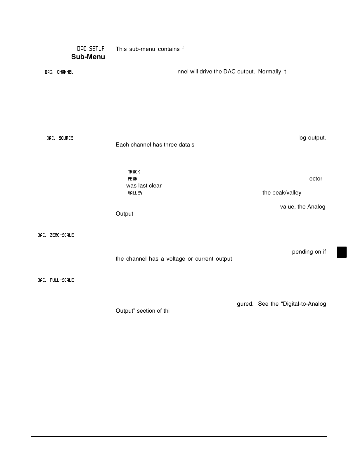
This sub-menu contains four items that control the Digital-to-Analog Converter
(DAC) output of the channel.
Menu Item This chooses which channel will drive the DAC output. Normally, the DAC located
on a particular channel will be driven by that channel, but that need not be the
case. For example, if a Mathematics Virtual channel is installed on the instrument, the output of this Virtual channel could be used to drive this channel’s DAC
output.
If the DAC is set-up to be driven by its own channel’s tracking value, the Analog
Output will have the frequency response specified by “Channel Specifications” on
page 37. Otherwise, the Analog Output will operate more slowly.
Menu Item This designates the data source of the channel monitored by the analog output.
Each channel has three data sources: the live tracking value (TRACK), its highest
value (PEAK), and its lowest value (VALLEY).
The options for this menu item are:
•“
•“
” means the live tracking value of the channel.
TTTTRRRRAAAACCCCKKKK
” means the highest value of the channel since the peak/valley detector
PPPPEEEEAAAAKKKK
was last cleared.
•“
” means the lowest value of the channel since the peak/valley detector
VVVVAAAALLLLLLLLEEEEYYYY
was last cleared.
If the DAC is set-up to be driven by its own channel’s tracking value, the Analog
Output will have the frequency response specified by “Channel Specifications” on
page 37. Otherwise, the Analog Output will operate more slowly.
DA
DACCCC.... ZERO-SCAL
ZERO-SCALEEEE
DADA
ZERO-SCALZERO-SCAL
DA
DACCCC.... FULL-SCAL
FULL-SCALEEEE
DADA
FULL-SCALFULL-SCAL
Menu Item This specifies what value, in engineering units, corresponds to zero output on the
Analog Output.
“Zero output” might be 0 Volts, 2.5 Volts, 5 Volts, 4 mA or 12 mA depending on if
the channel has a voltage or current output and how it is configured. See the
“Digital-to-Analog Output” section of this chapter for details.
Menu Item Specifies what value, in engineering units, corresponds to full output on the Ana-
log Output.
“Full output” might be 5 Volts, 10 Volts or 20 mA depending on if the channel has
a voltage or current output and how it is configured. See the “Digital-to-Analog
Output” section of this chapter for details.
FREQUENCY INPUT CHANNEL3
Additional Channels for SC Series Instrumentation page 41
Page 42
3.6.7
DIAG
DIAGNNNNOSTICS
OSTICS
DIAGDIAG
OSTICSOSTICS
Sub-Menu
DDDDAAAACCCCFFFFUUUULLLLL S
LSCCCCAAAALLLLEEEE
LSLS
DDDDAAAACCCCZZZZEEEERRRRO S
OSCCCCAAAALLLLEEEE
OSOS
VVVVEEEERRRRSSSSIIIIOOOONNNN INF
LLLLIIIINNNNEEEEAAAARRRRIIIIZZZZAAAATTTTIIIION
INFOOOO
INFINF
DDDDIIIISSSSPPPPLLLLAAAAYYYYAD
ADCCCC
ADAD
ON
ONON
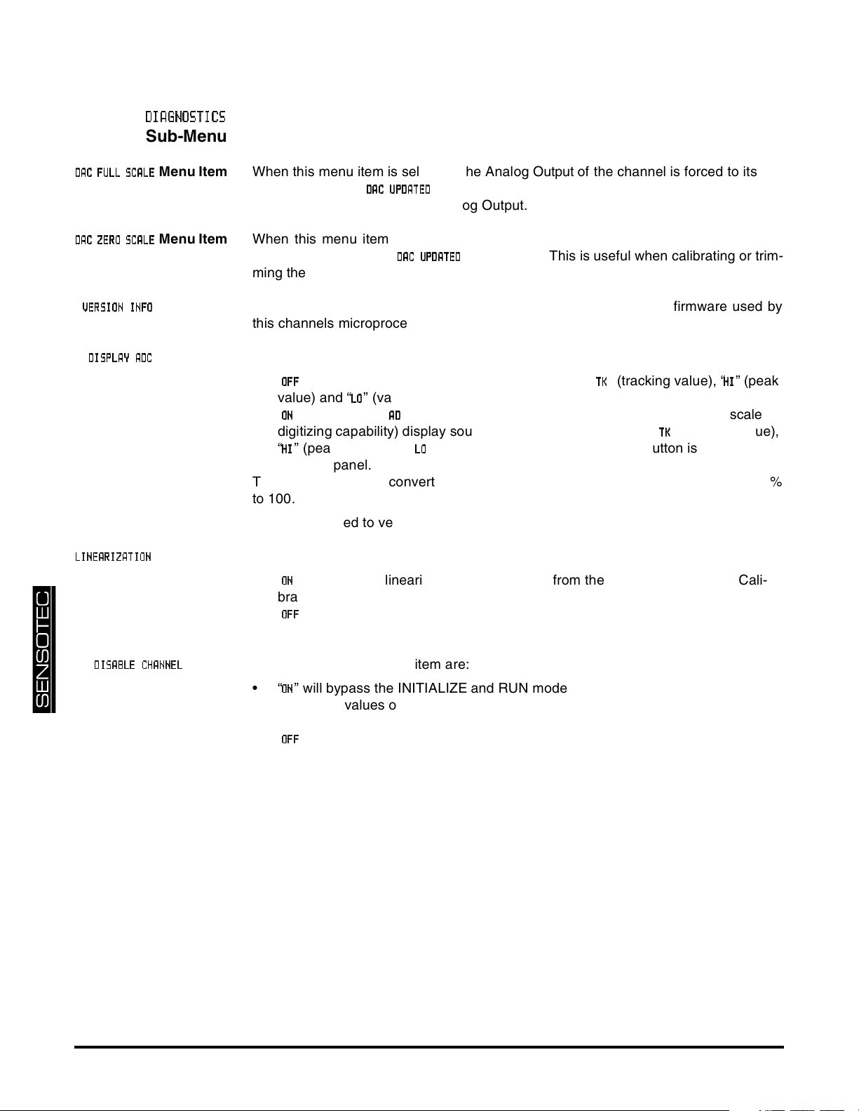
Menu Item When this menu item is selected, the Analog Output of the channel is forced to its full-
scale output, then
DDDDAAAACCCCUUUUPPPPDDDDAAAATTTTEEEEDDDD
is displayed. This is useful when calibrating or trimming
the readout connected to the Analog Output.
Menu Item When this menu item is selected, the Analog Output of the channel is forced to its
zero-scale output, then
DDDDAAAAC UP
CUPDDDDAAAATTTTEEEEDDDD
CUPCUP
is displayed. This is useful when calibrating or trim-
ming the readout connected to the Analog Output.
Menu Item This menu item displays the part number and revision level of the firmware used by
this channels microprocessor.
Menu Item The options for this menu item are:
•“
•“
” will allow the [VALUE] button to cycle through “
OOOOFFFFFFFF
value) and “
” will allow the “
OOOONNNN
” (valley value). This is the recommended option.
LLLLOOOO
” (percentage of the Analog-to-Digital converter’s full-scale
AAAADDDD
” (tracking value), “
TTTTKKKK
digitizing capability) display source to be available along with “
“
” (peak value) and “
HHHHIIII
” (valley value) when the [VALUE] button is pressed on
LLLLOOOO
” (peak
HHHHIIII
” (tracking value),
TTTTKKKK
the front panel.
The Analog-to-Digital converter counts are displayed as a percentage from -100.00%
to 100.00%.
This can be used to verify the correct operation of the input circuitry of the channel.
Menu Item The options for this menu item are:
•“
” will allow the linearization data obtained from the 5-Point Known Load Cali-
OOOONNNN
bration to affect a channel’s scaled values. This is the recommended option.
•“
” will not allow linearization data to effect the channel’s scaled values. This is
OOOOFFFFFFFF
useful when diagnosing problems in a calibration procedure.
DDDDIIIISSSSAAAABBBBLLLLEEEECCCCHHHHAAAANNNNNNNNEEEELLLL
Menu
Item
page 42 008-0608-01
The options for this menu item are:
•“
” will bypass the INITIALIZE and RUN modes of the channel. The track, peak
OOOONNNN
and valley values of the channel are forced to 0. This option is helpful when a
channel is installed but not being used.
•“
” will allow normal operation of the channel.
OOOOFFFFFFFF
Page 43
3.7 Analog Output Configuration
3.7.1 Identifying the Output Type
3.7.2 Channel Menu
Items
3.7.3 Output Selection
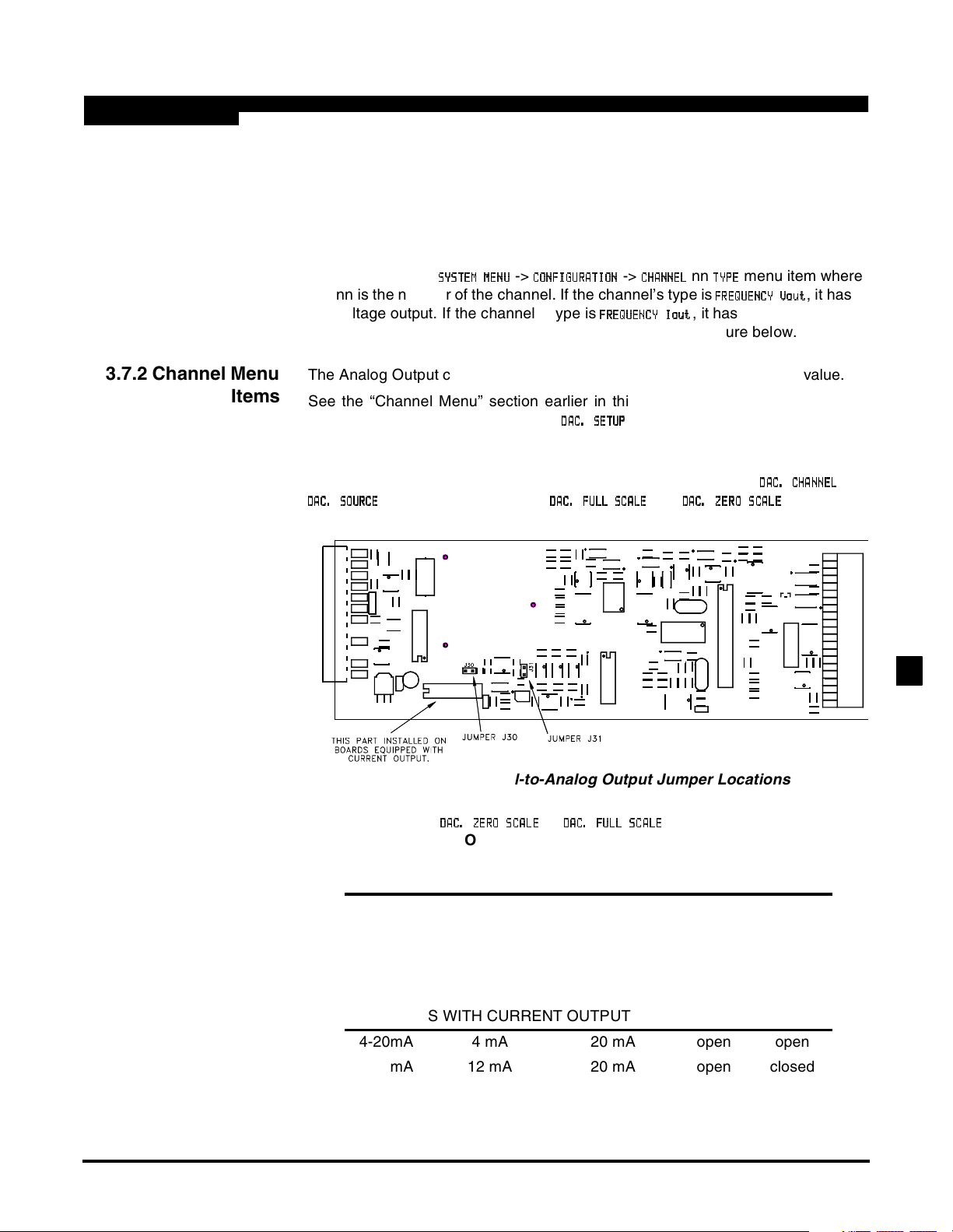
A Frequency Input channel is available with one of two types of digital-to-analog
(DAC) outputs: voltage or current. You can determine which type of output a
channel has by one of three ways:
• Consulting the instrument’s Customer Information Sheet
• Examining the
SSSSYYYYSSSSTTTTEEEEMMMM MEN
nn is the number of the channel. If the channel’s type is
voltage output. If the channel’s type is
MENUUUU
MENMEN
->
CCCCOOOONNNNFFFFIIIIGGGGUUUURRRRAAAATTTTIIIIOOOONNNN
->
CCCCHHHHAAAANNNNNNNNEEEELLLL
FFFFRRRREEEEQQQQUUUUEEEENNNNCCCCYYYY Iou
Ioutttt
IouIou
nn
menu item where
TTTTYYYYPPPPEEEE
FFFFRRRREEEEQQQQUUUUEEEENNNNCCCCY Vo
YVouuuutttt
YVoYVo
, it has a
, it has a current output.
• Examining the channel’s circuit board as shown in the figure below.
The Analog Output can be driven by any channel’s track, peak or valley value.
See the “Channel Menu” section earlier in this chapter for a complete listing of
SETUP menu items available on the
DDDDAAAACCCC.... SETU
sub-menu.
SETUPPPP
SETUSETU
Jumpers located on the channel’s circuit board determine what outputs are generated when the value selected to drive the Analog Output (from the
DDDDAAAACCCC.... SOURC
SOURCEEEE
SOURCSOURC
menu items) equals the
DA
DACCCC.... FULL S
FULL SCCCCAL
DADA
FULL SFULL S
ALEEEE
ALAL
and
DDDDAAAACCCC.... ZERO S
ZERO SCCCCAAAALLLLEEEE
ZERO SZERO S
DDDDAAAACCCC. CH
.CHAAAANNNNNNNNEEEELLLL
.CH.CH
settings.
and
Figure 3-5: Digital-to-Analog Output Jumper Locations
DDDDAAAACCCC....ZZZZEEEERRRROOOO SCAL
Output
SCALEEEE
SCALSCAL
DDDDAAAACCCC....FFFFUUUULLLLLLLL SCAL
SCALEEEE
SCALSCAL
Output
J30
jumper
J31
jumper
CHANNELS WITH VOLTAGE OUPUT
0-5V 2.5 Volts 5 Volts open closed
±5V 0 Volts 5 Volts open open
0-10V 5 Volts 10 Volts closed closed
±10V 0 Volts 10 Volts closed open
CHANNELS WITH CURRENT OUTPUT
4-20mA 4 mA 20 mA open open
4-20mA 12 mA 20 mA open closed
FREQUENCY INPUT CHANNEL3
Additional Channels for SC Series Instrumentation page 43
Page 44
3.8 Troubleshooting
3.8.1 Error Messages
See the “Error Messages” chapter of the “SC Series Instruction Manual”, Sensotec p/
n 008-0608-00, for information relating to error messages.
3.8.2 Common
Problems and
Solutions
Erratic Display Check “Wiring” on page 34 and make certain that nothing is connected to the pins
labeled as “N/C”.
Incorrect display
readings over 50kHz
Analog Output
Incorrect
Auxiliary Function
Pins Not Operating
The Frequency Input channel can only digitize signals with the minimum pulse specified in “Channel Specifications” on pag e37.
Make certain of the type of Analog Output (voltage or current) that the channel is
equipped with; see “Identifying the Output Type” on page43.
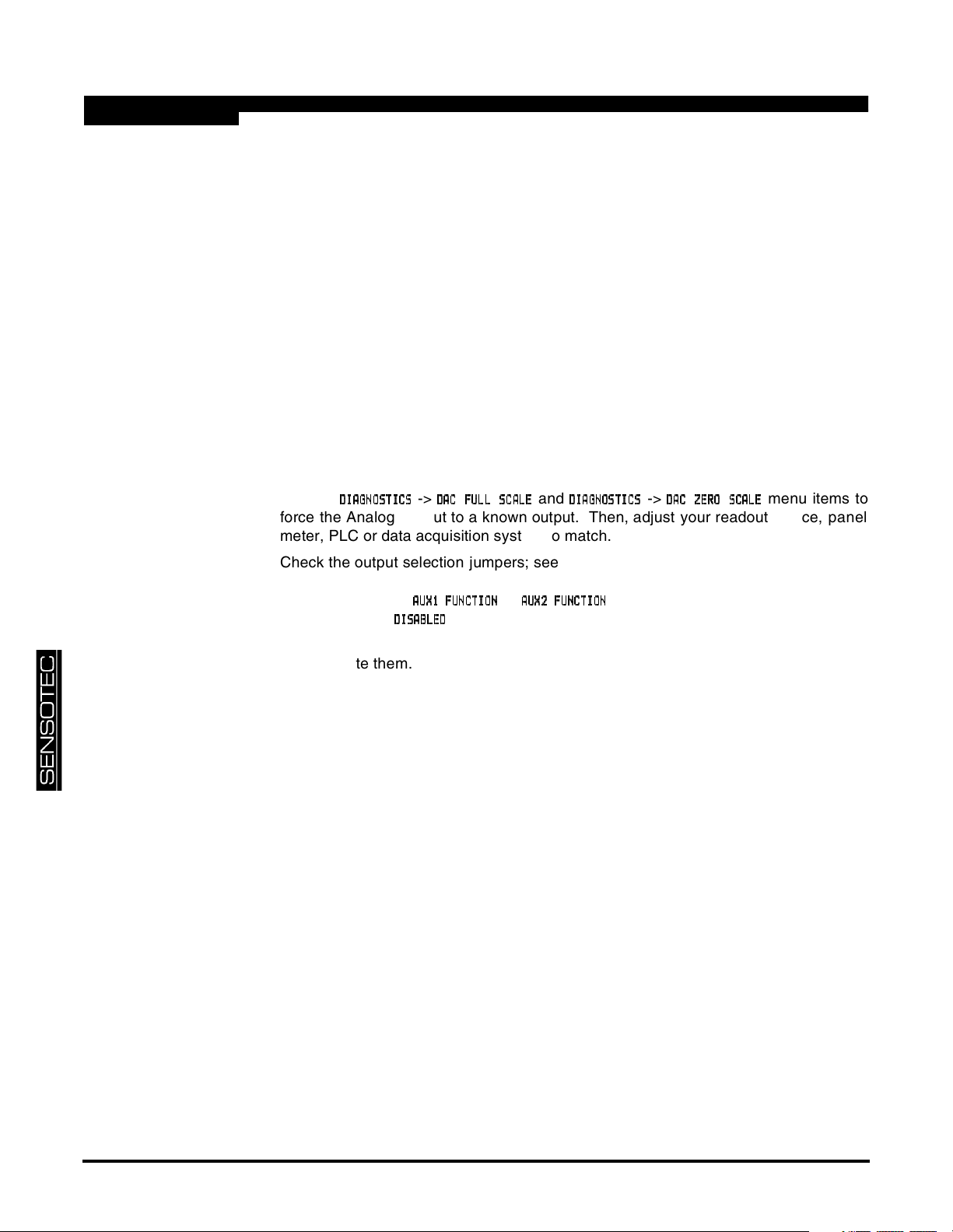
Use the
DDDDIIIIAAAAGGGGNO
NOSSSSTTTTIIIICCCCSSSS
NONO
->
DDDDAC
AC FFFFUL
ACAC
ULLLLLSC
SCAAAALLLLEEEE
ULUL
SCSC
and
DDDDIIIIAAAAGGGGNNNNOOOOSSSSTTTTIIIICCCCSSSS
->
DDDDAAAAC Z
CZEEEERRRRO S
CZCZ
OSCCCCAAAALLLLEEEE
OSOS
menu items to
force the Analog Output to a known output. Then, adjust your readout device, panel
meter, PLC or data acquisition system to match.
Check the output selection jumpers; see “Output Selection” on page 43.
Make sure that the
if they are set to
DDDDIIIISSSSAAAABBBBLLLLEEEEDDDD
AAAAUX
UX1111FFFFUUUUNNNNCCCCTTTTIIIIOOOONNNN
UXUX
then they will not operate.
or
AAAAUUUUXXXX2 F
2FUUUUNNNNCCCCTTTTIIIIOOOONNNN
2F2F
SETUP menu items are set correctly;
The Auxiliary Function (“AUX1” and “AUX2”) pins must be connected to pin 10, not pin
8, to activate them.
page 44 008-0608-01
Page 45
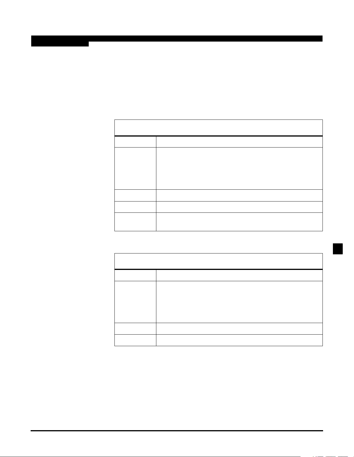
3.9 Communication Commands
3.9.1 Introduction
3.9.2 Descriptions
This section only documents the communication commands that affect the operation of the Frequency Input channel. Refer to document p/n 008-0610-00, “SC
Series Communications Guide” for details regarding serial communications. This
document can be downloaded from Sensotec’s web site, www.sensotec.com.
F0 Transmit Track Data
Purpose To transmit the channel’s tracking data value
Usage "
Example "
Reply "
Remarks The input channel continuously reads the RTD. This function
aacc
#
#
is the ‘pound’ or ‘hash’ character (ASCII decimal 35).
aa
is the two-character instrument address.
cc
is the two-character channel number
↵ is the ‘carriage return’ character (ASCII decimal 13).
#0001F0
0037.5
transmits the most recent reading.
↵"
F0
↵"
” (typical)
F9 Transmit Peak Data
Purpose To transmit the channel’s peak data value
Usage "
Example "
Reply "
aacc
#
#
is the ‘pound’ or ‘hash’ character (ASCII decimal 35).
aa
is the two-character instrument address.
cc
is the two-character channel number
↵ is the ‘carriage return’ character (ASCII decimal 13).
#0001F9
0162.5
↵"
F9
↵"
” (typical) or "
N/A
”
FREQUENCY INPUT CHANNEL3
Additional Channels for SC Series Instrumentation page 45
Page 46
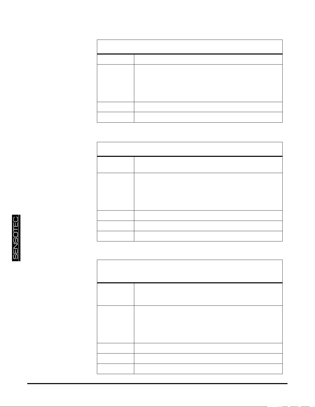
FA Transmit Valley Data
Purpose To transmit the channel’s valley data value
Usage "
Example "
Reply "
aacc
#
#
is the ‘pound’ or ‘hash’ character (ASCII decimal 35).
aa
is the two-character instrument address.
cc
is the two-character channel number
↵ is the ‘carriage return’ character (ASCII decimal 13).
#0001FA
-0012.5
↵"
FA
↵"
” (typical) or "
N/A
”
FB Clear Peak and Valley Data
Purpose To reset the channel’s peak and valley data values to the track
value.
Usage "
Example "
aacc
#
#
is the ‘pound’ or ‘hash’ character (ASCII decimal 35).
aa
is the two-character instrument address.
cc
is the two-character channel number
↵ is the ‘carriage return’ character (ASCII decimal 13).
#0001FB
FB
↵"
↵"
Reply "
Remarks This command is not available on the Model SC1000.
OK
” or "
N/A
”
FF Transmit Analog-to-Digital Converter
Reading
Purpose To transmit the Analog-to-Digital converter reading as a per-
centage from -100% to +100% of the A/D converters’s full
scale.
Usage "
Example "
Reply "
Remarks none
aacc
#
#
is the ‘pound’ or ‘hash’ character (ASCII decimal 35).
aa
is the two-character instrument address.
cc
is the two-character channel number
↵ is the ‘carriage return’ character (ASCII decimal 13).
#0001FF
50.000
↵"
FF
↵"
” (typical)
page 46 008-0608-01
Page 47
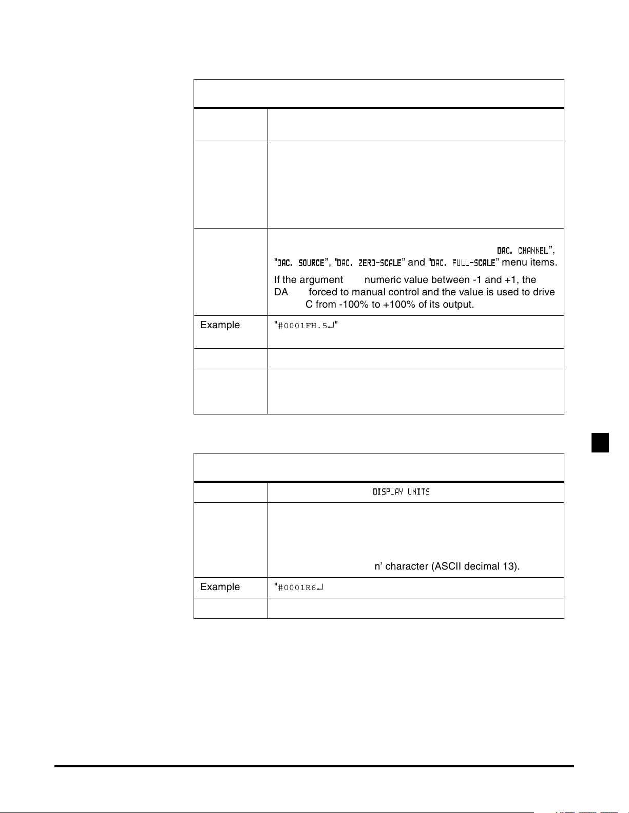
FH Write DAC Control Value
Purpose To control the channel’s Digital-to-Analog Converter (DAC)
manually or automatically.
Usage "
aaccFHn
#
#
is the ‘pound’ or ‘hash’ character (ASCII decimal 35).
aa
is the two-character instrument address.
cc
is the two-character channel number
n
is the argument defined below.
↵"
↵ is the ‘carriage return’ character (ASCII decimal 13).
Argument "
” returns the DAC to its normal automatic operation
AUTO
(power-on default). That is, it is controlled by the "
"
DDDDAAAACCCC. SO
.SOUUUURRRRCCCCEEEE
.SO.SO
”, "
DDDDAAAACCCC. Z
.ZEEEERRRROOOO----SSSSCCCCAAAALLLLEEEE
.Z.Z
” and "
DDDDAAAACCCC. F
.FUUUULLLLLLLL----SSSSCCCCAAAALLLLEEEE
.F.F
DDDDAAAACCCC....CCCCHHHHAAAANNNNNNNNEEEELLLL
”,
” menu items.
If the argument is a numeric value between -1 and +1, the
DAC is forced to manual control and the value is used to drive
the DAC from -100% to +100% of its output.
Example "
#0001FH.5
↵" will force channel 01’s DAC to +50% of full-
scale.
Reply "
OK
” or "
ERROR
”
Remarks You might wish to force a channel’s DAC to a certain output to
help calibrate the attached data acquisition system or other
device.
R6 Read Display Units
Purpose Reads the channel’s "
Usage "
aacc
#
#
is the ‘pound’ or ‘hash’ character (ASCII decimal 35).
aa
is the two-character instrument address.
cc
is the two-character channel number
↵" to read.
R6
DDDDIS
ISPPPPLLLLAAAAYYYY UNIT
ISIS
↵ is the ‘carriage return’ character (ASCII decimal 13).
Example "
#0001R6
↵”
Reply When reading: a four-character string.
” menu item
UNITSSSS
UNITUNIT
FREQUENCY INPUT CHANNEL3
Additional Channels for SC Series Instrumentation page 47
Page 48
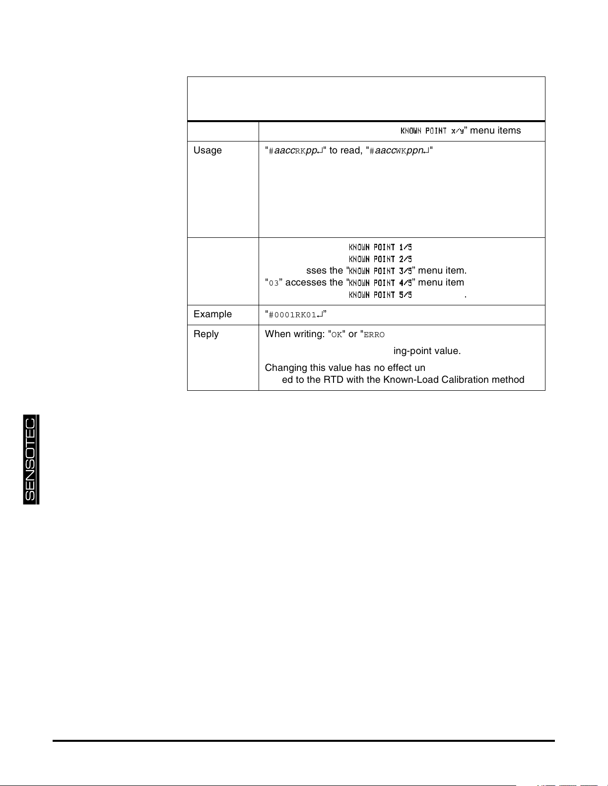
RK/WK Read/Write Known-Load Calibration
Point
Purpose Reads or writes the channel’s "
Usage "
aaccRKpp
#
#
is the ‘pound’ or ‘hash’ character (ASCII decimal 35).
aa
is the two-character instrument address.
cc
is the two-character channel number
pp
is the parameter defined below.
n
is the known-load calibration point in engineering units.
↵" to read, "
aaccWKppn
#
↵ is the ‘carriage return’ character (ASCII decimal 13).
Parameter "
Example "
Reply When writing: "OK
” accesses the "
00
"
” accesses the "
01
"
” accesses the "
02
"
” accesses the "
03
"
” accesses the "
04
#0001RK01
↵”
KKKKNNNNOOOOWWWWNNNN POINT 1
POINT 1////5555
POINT 1POINT 1
KKKKNNNNOOOOWWWWNNNN POINT 2
POINT 2////5555
POINT 2POINT 2
KKKKNNNNOOOOWWWWNNNN POINT 3
POINT 3////5555
POINT 3POINT 3
KKKKNNNNOOOOWWWWNNNN POINT 4
POINT 4////5555
POINT 4POINT 4
KKKKNNNNOOOOWWWWNNNN POINT 5
POINT 5////5555
POINT 5POINT 5
" or "
ERROR
”.
When reading: an ASCII-floating-point value.
Changing this value has no effect until the channel is re-calibrated to the RTD with the Known-Load Calibration method.
KKKKNNNNOOOOWWWWNNNN POINT x
POINT x////yyyy
POINT xPOINT x
↵" to write.
” menu item.
” menu item.
” menu item.
” menu item.
” menu item.
” menu items
page 48 008-0608-01
Page 49
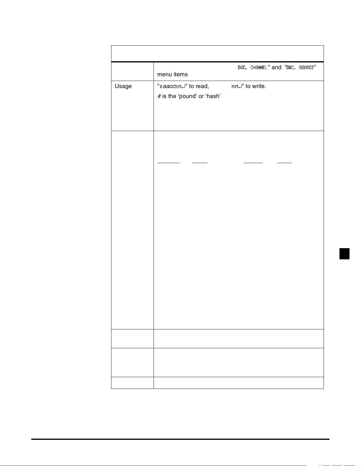
RM/WM Read/Write DAC Channel & Value
Purpose Reads or writes the channel’s "
DDDDAAAACCCC.... CHANNE
CHANNELLLL
CHANNECHANNE
” and "
DDDDAC
AC.... SOURC
SOURCEEEE
ACAC
SOURCSOURC
menu items
Usage "
aacc
#
#
is the ‘pound’ or ‘hash’ character (ASCII decimal 35).
aa
is the two-character instrument address.
cc
is the two-character channel number.
n
is the argument defined below.
↵" to read, "
RM
aaccWMn
#
↵" to write.
↵ is the ‘carriage return’ character (ASCII decimal 13).
Argument A number which selects a channel’s value. This number is
created by adding together the values of the desired options
as shown.
Channel
Value Source Value
01 1. TRACK 0.
02 2. PEAK 16.
03 3. VALLEY 32.
04 4.
05 5.
06 6.
07 7.
08 8.
09 9.
10 10.
11 11.
12 12.
13 13.
14 14.
15 15.
16 64.
17 65.
18 66.
19 67.
20 68.
21 69.
22 70.
23 71.
”
FREQUENCY INPUT CHANNEL3
Example "
#0001RM33
↵" will cause the channel 01’s DAC to monitor
channel 01’s valley value.
Reply When writing: "
When reading: a number corresponding to a channel number
and data value as shown above.
Remarks none
Additional Channels for SC Series Instrumentation page 49
OK
", "
ERROR
” or "
N/A
”.
Page 50
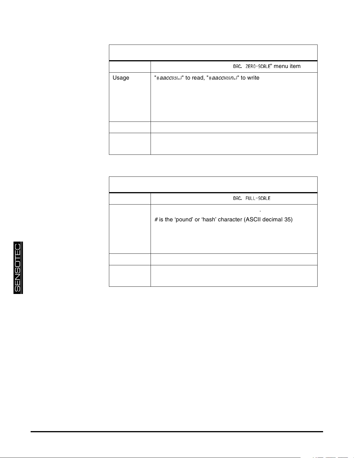
RN/WN Read/Write DAC Zero-Scale Value
Purpose Reads or writes the channel’s "
Usage "
aacc
#
#
is the ‘pound’ or ‘hash’ character (ASCII decimal 35).
aa
is the two-character instrument address.
cc
is the two-character channel number
n
is the zero Analog Output value in engineering units.
↵" to read, "
RN
aaccWNn
#
DDDDAAAACCCC.... ZERO-SCAL
ZERO-SCALEEEE
ZERO-SCALZERO-SCAL
↵" to write.
” menu item
↵ is the ‘carriage return’ character (ASCII decimal 13).
Example "
#0001WN-8000
Reply When writing: "
↵”
OK
" or "
ERROR
”.
When reading: an ASCII-floating-point value.
RO/WO Read/Write DAC Full-Scale Value
Purpose Reads or writes the channel’s "
Usage "
aacc
#
#
is the ‘pound’ or ‘hash’ character (ASCII decimal 35).
aa
is the two-character instrument address.
cc
is the two-character channel number
n
is the full Analog Output value in engineering units.
↵" to read, "
RO
aaccWOn
#
↵ is the ‘carriage return’ character (ASCII decimal 13).
DDDDAAAACCCC.... FULL-SCAL
FULL-SCALEEEE
FULL-SCALFULL-SCAL
↵" to write.
” menu item
Example "
#0001WO8000
Reply When writing: "
When reading: an ASCII-floating-point value.
↵”
OK
" or "
ERROR
”.
page 50 008-0608-01
Page 51
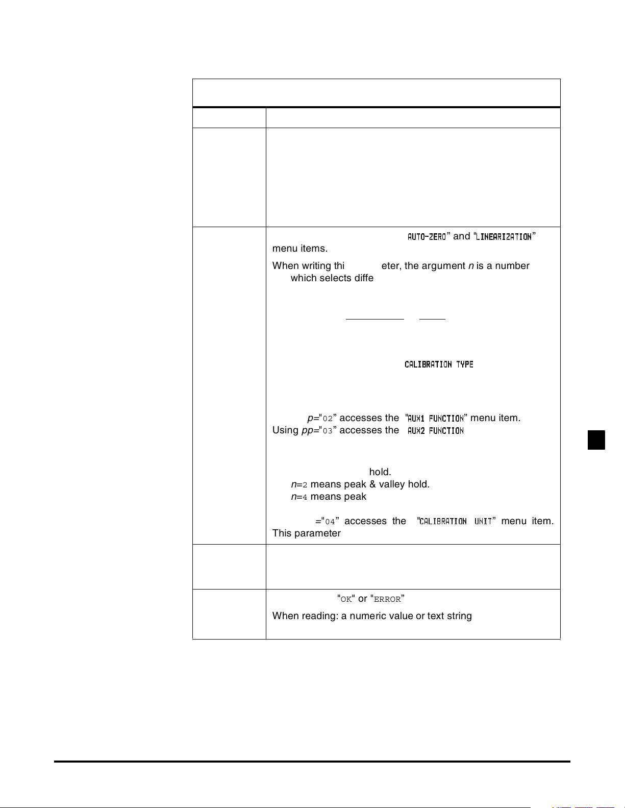
RP/WP Read/Write Operation
Purpose Read or write the operation settings of the channel
Usage "
Parameters
& Arguments
aaccRPpp
#
#
is the ‘pound’ or ‘hash’ character (ASCII decimal 35).
aa
is the two-character instrument address.
cc
is the two-character channel number.
pp
is one of the two-character parameters given below.
n
is the argument.
↵" to read, "
aaccWPppn
#
↵" to write.
↵ is the ‘carriage return’ character (ASCII decimal 13).
pp=
Using
"00” accesses the "
AAAAUUUUTTTTOOOO----ZZZZEEEERRRROOOO
” and "
LLLLIIIINNNNEEEEAAAARRRRIIIIZZZZAAAATTTTIIIIOOOONNNN
menu items.
When writing this parameter, the argument
n
is a number
which selects different operating features. This number is
created by adding together the values of the desired
options as shown.
Linearization
Value
OFF 0.
ON 16.
Using
pp=
"01” accesses the "
CCCCAAAALLLLIIIIBBBBRRRRAAAATTTTIIIIOOOONNNN TYP
” menu item.
TYPEEEE
TYPTYP
When reading this parameter:
n
=5 means 5-Point Known-Load Calibration.
Using
pp=
Using
"02” accesses the "
pp=
"03” accesses the "
AAAAUUUUXXXX1111 FUNCTIO
FUNCTIONNNN
FUNCTIOFUNCTIO
AAAAUUUUXXXX2222 FUNCTIO
FUNCTIONNNN
FUNCTIOFUNCTIO
” menu item.
” menu item.
When writing these parameters:
n
=0 means the Auxiliary Function pin is disabled.
n
=1 means track hold.
n
=2 means peak & valley hold.
n
=4 means peak & valley clear (edge triggered).
”
FREQUENCY INPUT CHANNEL3
Using
pp=
"04” accesses the "
This parameter can be read from, not written to.
Example Sending "
#0001WP0216
01’s Auxiliary 1 Function pin to activate the Tare function. The
instrument will reply with "
Reply When writing: "
When reading: a numeric value or text string according to the
information above.
Additional Channels for SC Series Instrumentation page 51
OK
CCCCAAAALLLLIIIIBBBBRRRRAAAATTTTIIIIOOOON U
NUNNNNIIIITTTT
NUNU
↵" will allow the assertion of channel
".
OK
" or "
ERROR
”
” menu item.
Page 52
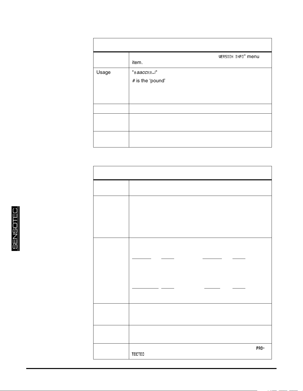
RR Read Version Info
Purpose Read version information found on the "
VVVVEEEERRRRSSSSIIIIOOOONNNN INF
INFOOOO
INFINF
” menu
item.
Usage "
aacc
#
#
is the ‘pound’ or ‘hash’ character (ASCII decimal 35).
aa
is the two-character instrument address.
cc
is the two-character channel number
RR
↵"
↵ is the ‘carriage return’ character (ASCII decimal 13).
Example "
#0001RR
↵"
Reply A text string such as
084-1169-01 04
Remarks This is the part number and version of the firmware used by
the channel’s microprocessor.
RT/WT Read/Write Front Panel Switch Operation
Purpose Reads or writes the operation of the front panel switches when
the Protection jumper is installed.
Usage "
aacc
#
#
is the ‘pound’ or ‘hash’ character (ASCII decimal 35).
aa
is the two-character instrument address.
cc
is the two-character channel number.
n
is the argument defined below.
↵" to read, "
RT
aaccWTn
#
↵" to write.
↵ is the ‘carriage return’ character (ASCII decimal 13).
Argument The argument is created by adding together the values of the
desired options as shown.
[VALUE]
Value [CLEAR] Value
ENABLED 0. ENABLED 0.
DISABLED 8. DISABLED 4.
[CHANNEL]
Value [TARE] Value
ENABLED 0. ENABLED 0.
DISABLED 2. DISABLED 1.
Example It is desired to disable the [TARE] button for channel 02 when
the Protection jumper is installed. Sending "
#0002WT1
↵" will
accomplish this.
Reply When writing: "
OK
" or "
ERROR
”.
When reading: an ASCII-floating-point value described above.
page 52 008-0608-01
Remarks If a disabled front panel button is pressed, the message "
” will appear on the display.
TTTTEEEECCCCTTTTEEEEDDDD
PPPPRRRROOOO----
Page 53

FREQUENCY INPUT CHANNEL3
Additional Channels for SC Series Instrumentation page 53
Page 54

page 54 008-0608-01
Page 55

4.1 Navigation instructions
• Press [UP]+[DOWN] to enter the SETUP menu mode.
• Press [UP] to move up.
• Press [DOWN] to move down.
• Press [ENTER] to select an item.
• Press [EXIT] to re-start the instrument.
Chapter 4
Setup Menu Reference
SETUP MENU REFERENCE4
Additional Channels for SC Series Instrumentation page 55
Page 56
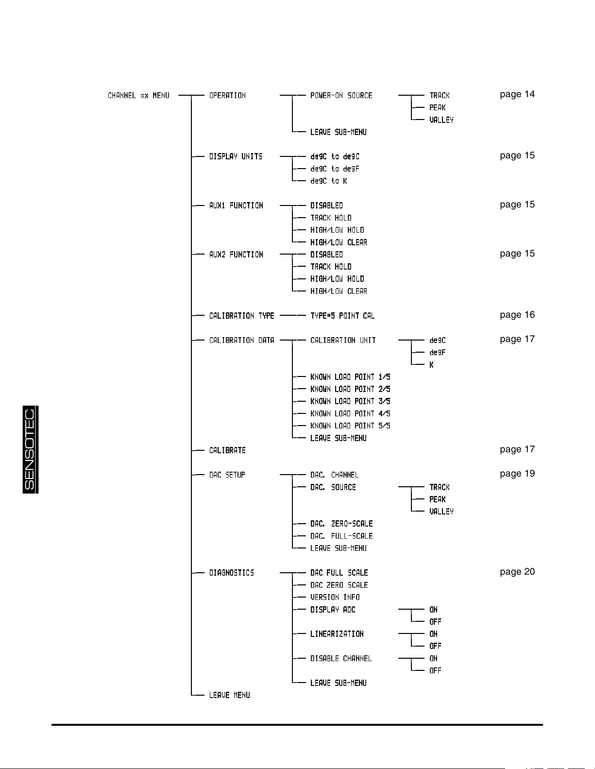
Table 4-1: RTD Input Channel Men u
CCCCHHHHAAAANNNNNNNNEEEELLLLxx ME
xx MENNNNUUUU
xx MExx ME
OOOOPPPPEEEERRRRAAAATTTTIIIIOOOONNNN
PPPPOOOOWWWWEEEERRRR----OOOONNNN SOURC
LLLLEEEEAAAAVVVVEEEE SUB-MEN
SOURCEEEE
SOURCSOURC
SUB-MENUUUU
SUB-MENSUB-MEN
TTTTRRRRAAAACCCCKKKK
PPPPEEEEAAAAKKKK
VVVVAAAALLLLLLLLEEEEYYYY
DDDDIIIISSSSPPPPLLLLAAAAYYYY UNI
UNITS
TS
UNIUNI
TSTS
ddddeeeeggggCCCCtod
to deeeeggggCCCC
to dto d
ddddeeeeggggCCCCtod
to deeeeggggFFFF
to dto d
ddddeeeeggggCCCCtttto K
oK
oKoK
AAAAUUUUXXXX1111 FUNCTI
FUNCTION
ON
FUNCTIFUNCTI
ONON
AAAAUUUUXXXX2222 FUNCTI
FUNCTION
ON
FUNCTIFUNCTI
ONON
DDDDIIIISSSSAAAABBBBLLLLEEEEDDDD
TTTTRRRRAAAACCCCKKKK HOL
HOLDDDD
HOLHOL
HHHHIIIIGGGGHHHH////LLLLOOOOWWWWHO
HHHHIIIIGGGGHHHH////LLLLOOOOWWWW CLEA
DDDDIIIISSSSAAAABBBBLLLLEEEEDDDD
TTTTRRRRAAAACCCCKKKK HOL
HHHHIIIIGGGGHHHH////LLLLOOOOWWWWHO
HHHHIIIIGGGGHHHH////LLLLOOOOWWWW CLEA
HOLDDDD
HOLHOL
HOLD
HOHO
CLEARRRR
CLEACLEA
HOLD
HOHO
CLEARRRR
CLEACLEA
LD
LDLD
LD
LDLD
CCCCAAAALLLLIIIIBBBBRRRRAAAATI
TIOOOONNNN TYP
TITI
TYPEEEE
TYPTYP
TTTTYYYYPPPPEEEE====5555 POINT CA
POINT CALLLL
POINT CAPOINT CA
CCCCAAAALLLLIIIIBBBBRRRRAAAATI
TIOOOONNNN DAT
DATAAAA
TITI
DATDAT
CCCCAAAALLLLIIIIBBBBRRRRAAAATE
TE
TETE
CCCCAAAALLLLIIIIBBBBRRRRAAAATI
TIOOOONNNN UNI
UNITTTT
TITI
UNIUNI
KKKKNNNNOOOOWWWWNNNN LOAD POINT 1/
LOAD POINT 1/5555
LOAD POINT 1/LOAD POINT 1/
KKKKNNNNOOOOWWWWNNNN LOAD POINT 2/
LOAD POINT 2/5555
LOAD POINT 2/LOAD POINT 2/
KKKKNNNNOOOOWWWWNNNN LOAD POINT 3/
LOAD POINT 3/5555
LOAD POINT 3/LOAD POINT 3/
KKKKNNNNOOOOWWWWNNNN LOAD POINT 4/
LOAD POINT 4/5555
LOAD POINT 4/LOAD POINT 4/
KKKKNNNNOOOOWWWWNNNN LOAD POINT 5/
LOAD POINT 5/5555
LOAD POINT 5/LOAD POINT 5/
LLLLEEEEAAAAVVVVEEEE SUB-MEN
SUB-MENUUUU
SUB-MENSUB-MEN
ddddeeeeggggCCCC
ddddeeeeggggFFFF
KKKK
DDDDAAAACCCC SETU
SETUPPPP
SETUSETU
DDDDAAAACCCC.... CHANNE
CHANNELLLL
CHANNECHANNE
DDDDAAAACCCC.... SOUR
SOURCE
CE
SOURSOUR
CECE
DDDDAAAACCCC.... ZERO-SCAL
ZERO-SCALEEEE
ZERO-SCALZERO-SCAL
DDDDAAAACCCC.... FULL-SCAL
FULL-SCALEEEE
FULL-SCALFULL-SCAL
LLLLEEEEAAAAVVVVEEEE SUB-MEN
SUB-MENUUUU
SUB-MENSUB-MEN
TTTTRRRRAAAACCCCKKKK
PPPPEEEEAAAAKKKK
VVVVAAAALLLLLLLLEEEEYYYY
DDDDIIIIAAAAGGGGNNNNOOOOSSSSTTTTIIIICCCCSSSS
LLLLEEEEAAAAVVVVEEEE MEN
MENUUUU
MENMEN
DDDDAAAACCCC FULL SC
FULL SCAL
FULL SCFULL SC
DDDDAAAACCCC ZERO SC
ZERO SCAL
ZERO SCZERO SC
VVVVEEEERRRRSSSSIIIIOOOONNNN INF
DDDDIIIISSSSPPPPLLLLAAAAYYYYAAAADC
LLLLIIIINNNNEEEEAAAARRRRIIIIZZZZAAAATI
DDDDIIIISSSSAAAABBBBLLLLEEEE CHANNE
LLLLEEEEAAAAVVVVEEEE SUB-MEN
ALEEEE
ALAL
ALEEEE
ALAL
INFOOOO
INFINF
DC
DCDC
TIOOOONNNN
TITI
CHANNELLLL
CHANNECHANNE
SUB-MENUUUU
SUB-MENSUB-MEN
OOOONNNN
OOOOFFFFFFFF
OOOONNNN
OOOOFFFFFFFF
OOOONNNN
OOOOFFFFFFFF
page 14
page 15
page 15
page 15
page 16
page 17
page 17
page 19
page 20
page 56 008-0608-01
Page 57
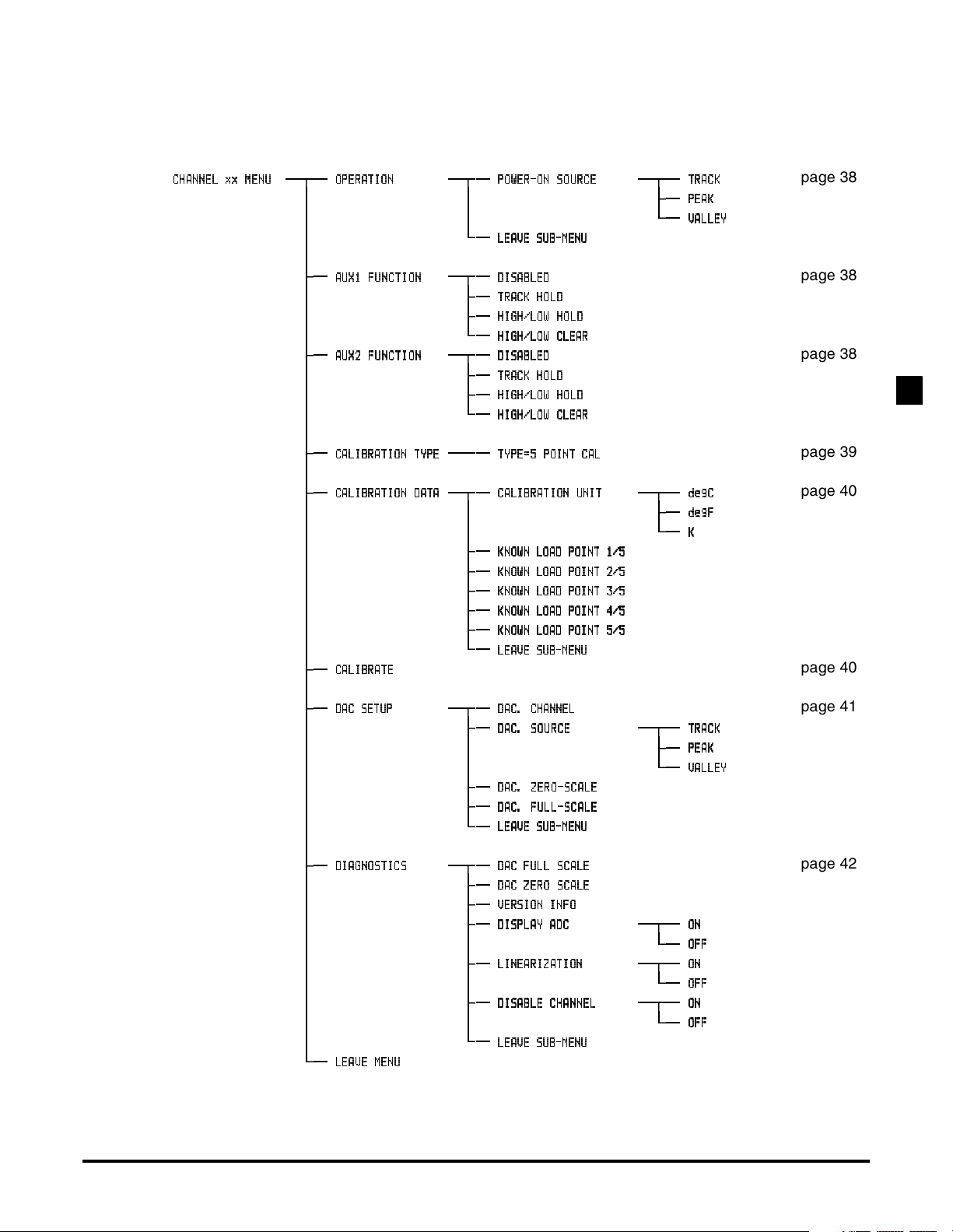
Table 4-2: Frequency Input Channel Menu
CCCCHHHHAAAANNNNNNNNEEEELLLLxx ME
xx MENNNNUUUU
xx MExx ME
OOOOPPPPEEEERRRRAAAATTTTIIIIOOOONNNN
PPPPOOOOWWWWEEEERRRR----OOOONNNN SOURC
LLLLEEEEAAAAVVVVEEEE SUB-MEN
SOURCEEEE
SOURCSOURC
SUB-MENUUUU
SUB-MENSUB-MEN
TTTTRRRRAAAACCCCKKKK
PPPPEEEEAAAAKKKK
VVVVAAAALLLLLLLLEEEEYYYY
AAAAUUUUXXXX1111 FUNCTI
FUNCTION
ON
FUNCTIFUNCTI
ONON
AAAAUUUUXXXX2222 FUNCTI
FUNCTION
ON
FUNCTIFUNCTI
ONON
DDDDIIIISSSSAAAABBBBLLLLEEEEDDDD
TTTTRRRRAAAACCCCKKKK HOL
HOLDDDD
HOLHOL
HHHHIIIIGGGGHHHH////LLLLOOOOWWWWHO
HHHHIIIIGGGGHHHH////LLLLOOOOWWWW CLEA
DDDDIIIISSSSAAAABBBBLLLLEEEEDDDD
TTTTRRRRAAAACCCCKKKK HOL
HHHHIIIIGGGGHHHH////LLLLOOOOWWWWHO
HHHHIIIIGGGGHHHH////LLLLOOOOWWWW CLEA
HOLDDDD
HOLHOL
HOLD
HOHO
CLEARRRR
CLEACLEA
HOLD
HOHO
CLEARRRR
CLEACLEA
LD
LDLD
LD
LDLD
CCCCAAAALLLLIIIIBBBBRRRRAAAATI
TIOOOONNNN TYP
TITI
TYPEEEE
TYPTYP
TTTTYYYYPPPPEEEE====5555 POINT CA
POINT CALLLL
POINT CAPOINT CA
CCCCAAAALLLLIIIIBBBBRRRRAAAATI
TIOOOONNNN DAT
DATAAAA
TITI
DATDAT
CCCCAAAALLLLIIIIBBBBRRRRAAAATE
TE
TETE
CCCCAAAALLLLIIIIBBBBRRRRAAAATI
TIOOOONNNN UNI
UNITTTT
TITI
UNIUNI
KKKKNNNNOOOOWWWWNNNN LOAD POINT 1/
LOAD POINT 1/5555
LOAD POINT 1/LOAD POINT 1/
KKKKNNNNOOOOWWWWNNNN LOAD POINT 2/
LOAD POINT 2/5555
LOAD POINT 2/LOAD POINT 2/
KKKKNNNNOOOOWWWWNNNN LOAD POINT 3/
LOAD POINT 3/5555
LOAD POINT 3/LOAD POINT 3/
KKKKNNNNOOOOWWWWNNNN LOAD POINT 4/
LOAD POINT 4/5555
LOAD POINT 4/LOAD POINT 4/
KKKKNNNNOOOOWWWWNNNN LOAD POINT 5/
LOAD POINT 5/5555
LOAD POINT 5/LOAD POINT 5/
LLLLEEEEAAAAVVVVEEEE SUB-MEN
SUB-MENUUUU
SUB-MENSUB-MEN
ddddeeeeggggCCCC
ddddeeeeggggFFFF
KKKK
DDDDAAAACCCC SETU
SETUPPPP
SETUSETU
DDDDAAAACCCC.... CHANNE
CHANNELLLL
CHANNECHANNE
DDDDAAAACCCC.... SOUR
SOURCE
CE
SOURSOUR
CECE
DDDDAAAACCCC.... ZERO-SCAL
ZERO-SCALEEEE
ZERO-SCALZERO-SCAL
DDDDAAAACCCC.... FULL-SCAL
FULL-SCALEEEE
FULL-SCALFULL-SCAL
LLLLEEEEAAAAVVVVEEEE SUB-MEN
SUB-MENUUUU
SUB-MENSUB-MEN
TTTTRRRRAAAACCCCKKKK
PPPPEEEEAAAAKKKK
VVVVAAAALLLLLLLLEEEEYYYY
DDDDIIIIAAAAGGGGNNNNOOOOSSSSTTTTIIIICCCCSSSS
LLLLEEEEAAAAVVVVEEEE MEN
MENUUUU
MENMEN
DDDDAAAACCCC FULL SC
FULL SCAL
FULL SCFULL SC
DDDDAAAACCCC ZERO SC
ZERO SCAL
ZERO SCZERO SC
VVVVEEEERRRRSSSSIIIIOOOONNNN INF
DDDDIIIISSSSPPPPLLLLAAAAYYYYAAAADC
LLLLIIIINNNNEEEEAAAARRRRIIIIZZZZAAAATI
DDDDIIIISSSSAAAABBBBLLLLEEEE CHANNE
LLLLEEEEAAAAVVVVEEEE SUB-MEN
ALEEEE
ALAL
ALEEEE
ALAL
INFOOOO
INFINF
DC
DCDC
TIOOOONNNN
TITI
CHANNELLLL
CHANNECHANNE
SUB-MENUUUU
SUB-MENSUB-MEN
OOOONNNN
OOOOFFFFFFFF
OOOONNNN
OOOOFFFFFFFF
OOOONNNN
OOOOFFFFFFFF
page 38
page 38
page 38
SETUP MENU REFERENCE4
page 39
page 40
page 40
page 41
page 42
Additional Channels for SC Series Instrumentation page 57
Page 58

page 58 008-0608-01
Page 59

Index
C
Communications Guide 6
Customer Information Sheet 6
F
Frequency Input channel
Analog Output 41–44
Auxilliary Function pins 38, 44
calibration 36
communication commands 45
features 33
frequency response 37
Getting Started Quickly 33
remote control of Track/Hold, Peak/Valley clear,
Peak/Valley hold 38
SETUP menu 38
software revision 42
specifications 37
step response 37
troubleshooting 44
wiring 34
R
RTD Input channel
Analog Output 19, 21–22
Auxilliary Function pins 15, 22
calibration 12
communication commands 23
display
message 22
OVLD
units of measure 15
features 9
frequency response 13
getting started quickly 9
remote control of Track/Hold, Peak/Valley clear,
Peak/Valley hold 15
SETUP Menu 14
software revision 20
specifications 13
step response 13
troubleshooting 22
wiring 10
S
Serial Communications Guide 6
INDEX
Additional Channels for SC Series Instrumentation page 59
Page 60

page 60 008-0608-01
Page 61

Warranty/Repair Policy
Limitation of Remedy and
Disclaimer of Warranty
Obtaining Service Under
Warranty
Any of our products which, under normal operating conditions, proves defective in
material or in workmanship within one year from the date of shipment by Sensotec, Inc., will be repaired or replaced free of charge, provided that the buyer (1)
promptly notifies Sensotec, Inc. of any such defect; (2) provides Sensotec, Inc.
with satisfactory proof of the defect and that the product was properly installed,
maintained, and operated within the limits of rated and normal usage; and (3)
obtains from Sensotec, Inc. authorization to return the product. Any such product
shall be returned with transportation charges prepaid. The replacement product
will be shipped F.O.B. our plant.
The remedy set forth herein does not extend to any product or part thereof which,
under normal usage, has an inherently shorter useful life than one year. The remedy set forth herein does not apply to damage or to defects in any product caused
by the buyer’s misuse or neglect, nor does it apply to any product which has been
repaired or disassembled which, in the sole judgement of Sensotec, Inc. affects
the performance of the product.
The remedy set forth herein is the buyer's exclusive remedy, and will satisfy all
obligations of Sensotec, Inc. whether based on contract, negligence, or otherwise.
Sensotec, Inc. is not responsible for any incidental or consequential loss or damage which might result from a failure of any Sensotec, Inc. product.
THIS EXPRESS WARRANTY IS MADE IN LIEU OF ANY AND ALL OTHER
WARRANTIES, EXPRESSED OR IMPLIED, INCLUDING IMPLIED WARRANTY
OF MERCHANTABILITY OR FITNESS FOR PARTICULAR PURPOSE.
Advanced authorization is required prior to the return to Sensotec, Inc. Before
returning the items, either write to the Repair Department c/o Sensotec, Inc., 2080
Arlingate Lane, Columbus, Ohio 43228, or call (800) 848-6564 with: 1) a part
number; 2) a serial number of the defective product; 3) a technical description* of
the defect; 4) a no-charge purchase order number (so products can be returned to
you correctly); and 5) ship and bill addresses. Shipment to Sensotec, Inc. shall be
at Buyer's expense and repaired or replacement items will be shipped F.O.B. our
plant in Columbus, Ohio. Non-verified problems or defects may be subject to an
evaluation charge. Please return the original calibration data with the unit.
WARRANTY/REPAIR POLICY
Obtaining Non-warranty
Service
Repair Warranty All repairs of Sensotec, Inc. products are warranted for a period of 90 days from
Advance authorization is required prior to the return to Sensotec, Inc. Before
returning the item, either write to the Repair Department c/o Sensotec, Inc., 2080
Arlingate Lane, Columbus, Ohio 43228, or call (800) 848-6564 with: 1) a part
number; 2) a serial number of the defective product; 3) a technical description* of
the malfunction; 4) a purchase order number to cover Sensotec, Inc.'s repair cost;
and 5) ship and bill addresses. After the product is evaluated by Sensotec, Inc.,
we will contact you to provide the estimated repair costs before proceeding. The
minimum evaluation charge is $95. Shipment to Sensotec, Inc. shall be at Buyer's
expense and repaired items will be shipped to you F.O.B., our plant in Columbus,
Ohio. Please return the original calibration data with the unit.
date of shipment. This warranty applies only to those items which were found
defective and repaired. It does not apply to products in which no defect was found
and returned as is or merely re-calibrated. Out of warranty products may not be
capable of being returned to the exact original specifications or dimensions.
*Technical description of the defect: In order to properly repair a product, it is necessary for
Sensotec, Inc. to receive information specifying the reason the product is being returned.
Specific test data, written observations on the failure and specific corrective action you
require is needed.
Additional Channels for SC Series Instrumentation page 61
Page 62

(800)848-6564
2080 Arlingate Lane
Columbus, Ohio 43228
Tel: (614)850-5000
Fax: (614)850-1111
E-mail: [email protected]
http://www.sensotec.com
 Loading...