

Page 1
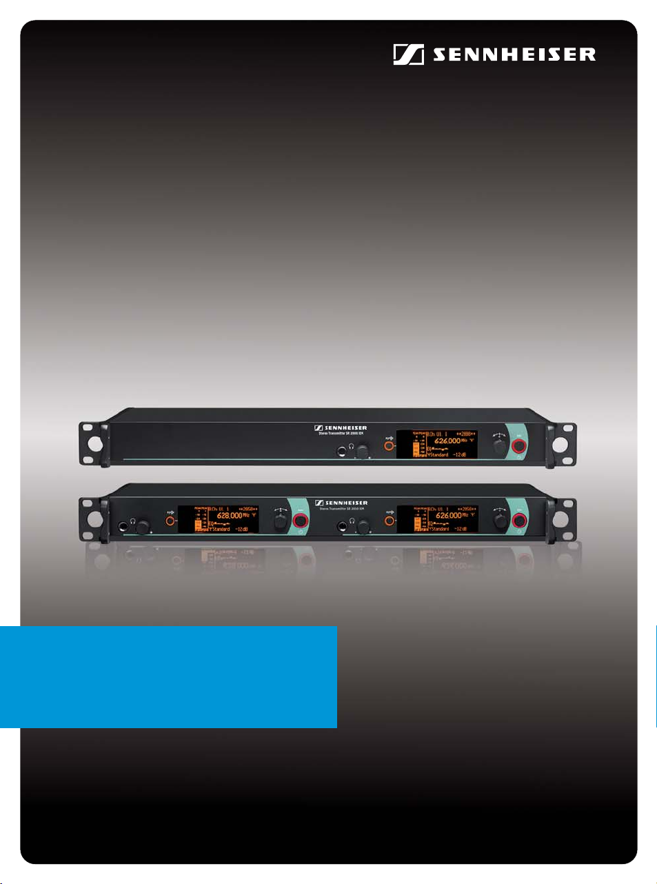
SR
2000 IEM
SR 2050 IEM
Instruction manual
Page 2

Contents
For more detailed information on the individual sections of this instruction manual, visit the corresponding product page on our website at www.sennheiser.com.
Contents
Important safety instructions ............................................................................................................................................................. 2
The SR 2000 IEM and SR 2050 IEM transmitters ............................................................................................................................. 4
The frequency bank system .............................................................................................................................................................. 4
Areas of application ............................................................................................................................................................................ 5
Delivery includes ..................................................................................................................................................................................... 5
Product overview .................................................................................................................................................................................... 6
Overview of the SR 2000 IEM/SR 2050 IEM transmitter ............................................................................................................ 6
Overview of the displays ................................................................................................................................................................... 7
Putting the transmitter into operation ............................................................................................................................................. 8
Setting up the transmitter on a flat surface ................................................................................................................................. 8
Mounting the transmitter into a 19” rack ..................................................................................................................................... 8
Connecting the antennas .................................................................................................................................................................. 8
Connecting an audio source to the input sockets ...................................................................................................................... 11
Daisy chaining audio signals ........................................................................................................................................................... 11
Connecting devices to the output sockets ................................................................................................................................... 12
Connecting transmitters in a network .......................................................................................................................................... 12
Connecting the mains cable ............................................................................................................................................................ 12
Using the transmitter .......................................................................................................................................................................... 13
Switching the transmitter on/off .................................................................................................................................................. 13
Deactivating the lock mode temporarily ...................................................................................................................................... 14
Activating/deactivating the RF signal .......................................................................................................................................... 14
Adjusting the audio channels ......................................................................................................................................................... 14
Monitoring the audio signal via headphones .............................................................................................................................. 15
Synchronizing transmitters and EK 2000 IEM receivers via the infra-red interface ........................................................... 15
Using the operating menu .................................................................................................................................................................. 18
The buttons ........................................................................................................................................................................................ 18
Overview of the operating menu ................................................................................................................................................... 18
Working with the operating menu ................................................................................................................................................ 20
Synchronizing the transmitter with an EK 2000 IEM receiver ................................................................................................... 22
Cleaning the transmitter ..................................................................................................................................................................... 23
Accessories ............................................................................................................................................................................................. 23
If a problem occurs ... ........................................................................................................................................................................... 24
Specifications ......................................................................................................................................................................................... 25
Manufacturer Declarations ................................................................................................................................................................. 26
1
Page 3
Important safety instructions
Important safety instructions
1. Read these instructions.
2. Keep these instructions. Always include these instructions when passing the transmitter
on to third parties.
3. Heed all warnings.
4. Follow all instructions.
5. Do not use this apparatus near water.
6. Clean only with a dry cloth.
7. Do not block any ventilation openings. Install in accordance with the manufacturer’s
instructions.
8. Do not install near any heat sources such as radiators, heat registers, stoves, or other
apparatus (including amplifiers) that produce heat.
9. Do not defeat the safety purpose of the polarized or grounding-type plug. A polarized
plug has two blades with one wider than the other. A grounding type plug has two blades
and a third grounding prong. The wide blade or the third prong are provided for your
safety. If the provided plug does not fit into your outlet, consult an electrician for replacement of the obsolete outlet.
10.Protect the power cord from being walked on or pinched, particularly at plugs, convenience receptacles, and the point where they exit from the apparatus.
11.Only use attachments/accessories specified by the manufacturer.
12.Use only with the cart, stand, tripod, bracket, or table specified by the manufacturer, or
sold with the apparatus. When a cart is used, use caution when moving the cart/apparatus combination to avoid injury from tip-over.
13.Unplug this apparatus during lightning storms or when unused for long periods of time.
14.Refer all servicing to qualified service personnel.
Servicing is required when the apparatus has been damaged in any way, such as power
supply cord or plug is damaged, liquid has been spilled or objects have fallen into the
apparatus, when the apparatus has been exposed to rain or moisture, does not operate
normally, or has been dropped.
15.To completely disconnect this apparatus from the AC mains, disconnect the power supply
cord plug from the AC receptacle.
16.WARNING: To reduce the risk of fire or electric shock, do not expose this apparatus to rain
or moisture.
17.Do not expose this equipment to dripping or splashing and ensure that no objects filled
with liquids, such as vases, are placed on the equipment.
18.The mains plug of the power supply cord shall remain readily operable.
Hazard warnings on the rear of the transmitter
The label shown on the left is attached to the rear of the transmitter. The symbols on this
label have the following meaning:
This symbol is intended to alert the user to the presence of uninsulated dangerous voltage
within the transmitter’s enclosure that may be of sufficient magnitude to constitute risk of
fire or electric shock.
2
Page 4

Important safety instructions
This symbol is intended to alert the user to the risk of electric shock if the transmitter is
opened. There are no user serviceable parts inside. Refer servicing to qualified personnel only.
This symbol is intended to alert the user to the presence of important operating and maintenance instructions in the literature accompanying this transmitter.
Overloading
Do not overload wall outlets and extension cables as this may result in fire and electric shock.
Replacement parts
When replacement parts are required, be sure the service technician uses replacement parts
specified by Sennheiser or those having the same characteristics as the original part.
Unauthorized substitutions may result in fire, electric shock, or other hazards.
Safety check
Upon completion of any service or repairs to this device, ask the service technician to perform
safety checks to determine that the device is in safe operating order.
Danger of hearing damage due to high volumes
This is a professional transmitter. Commercial use is subject to the rules and regulations of
the trade association responsible. Sennheiser, as the manufacturer, is therefore obliged to
expressly point out possible health risks arising from use.
This transmitter is capable of producing sound pressure exceeding 85 dB(A). 85 dB(A) is the
sound pressure corresponding to the maximum permissible volume which is by law (in some
countries) allowed to affect your hearing for the duration of a working day. It is used as a
basis according to the specifications of industrial medicine. Higher volumes or longer durations can damage your hearing. At higher volumes, the duration must be shortened in order
to prevent hearing damage. The following are sure signs that you have been subjected to
excessive noise for too long a time:
• You can hear ringing or whistling sounds in your ears.
• You have the impression (even for a short time only) that you can no longer hear high
notes.
Intended use
Intended use of the SR 2000 IEM and SR 2050 IEM transmitters includes:
• having read these instructions, especially the chapter “Important safety instructions”,
• using the device within the operating conditions and limitations described in this instruction manual.
“Improper use” means using the device other than as described in these instructions, or
under operating conditions which differ from those described herein.
3
Page 5
The SR 2000 IEM and SR 2050 IEM transmitters
The SR 2000 IEM and SR 2050 IEM transmitters
With the SR 2000 IEM and SR 2050 IEM 2-channel/stereo monitoring transmitters, musicians, video and sound amateurs, reporters/broadcasters, etc. can directly monitor the
received sound signals without troublesome cables or monitor speakers being required. In
addition, the transmitters can also be used for any application where talkback signals are to
be transmitted.
Features of the SR 2000 IEM and SR 2050 IEM transmitters:
• Optimized PLL synthesizer and microprocessor technology
•Stereo/mono selection
• HDX noise reduction system
• Switching bandwidth of up to 75 MHz
• Safe configuration of a multi-channel system using the WSM
• Easy setup of a multi-channel system using the Easy Setup Sync function
The frequency bank system
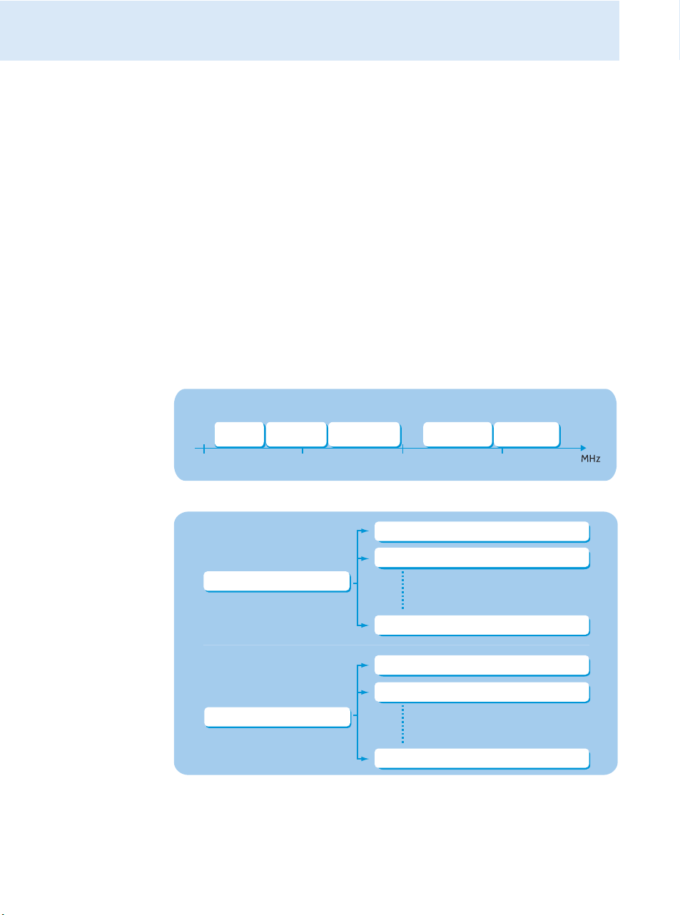
The transmitters are available in 5 UHF frequency ranges with up to 3,000 transmission
frequencies per frequency range:
Aw:
Range
558 – 626
Range
516 – 558
500 600 700 800
Gw:
Range Bw:
626 – 698
Range
718 – 790
Cw:
Range Dw:
790 – 865
Each frequency range (Aw–Dw, Gw) offers 26 frequency banks with up to 32 channels each:
Channel 1 – frequency preset
Channel 2 – frequency preset
Frequency bank 1... 20
Channel 32 – frequency preset
Channel 1 – freely selectable frequency
Channel 2 – freely selectable frequency
Frequency bank U1 ... U6
Channel 32 – freely selectable frequency
4
Page 6

Delivery includes
Each of the channels in the frequency banks “1” to “20” has been factory-preset to a fixed
transmission frequency (frequency preset). The factory-preset frequencies within one
frequency bank are intermodulation-free. These frequencies cannot be changed.
For an overview of the frequency presets, please refer to the supplied frequency information
sheet. Updated versions of the frequency information sheet can be downloaded from the
corresponding product page on our website at www.sennheiser.com.
The frequency banks “U1” to “U6” allow you to freely select and store transmission frequencies. It might be that these transmission frequencies are not intermodulation-free (see
page 22).
Areas of application
The transmitters can be combined with the EK 2000 IEM diversity receiver. For more information, visit our website at www.sennheiser.com.
This receiver is available in the same UHF frequency ranges and is equipped with the same
frequency bank system with factory-preset frequencies. An advantage of the factory-preset
frequencies is that
• a transmission system is ready for immediate use after switch-on,
• several transmission systems can be operated simultaneously on the preset frequencies
without causing intermodulation interference.
Delivery includes
The packaging contains the following items:
1 SR 2000 IEM transmitter or 1 SR 2050 IEM twin transmitter
3 mains cables (with EU, UK and US plug)
1 rod antenna (SR 2000 IEM) or 2 rod antennas (SR 2050 IEM)
1 instruction manual
1 frequency information sheet
1 RF licensing information sheet
4 self-adhesive device feet
5
Page 7
Product overview
50/60Hz 0.2A ETHERNET RJ-45
B
100 - 240V
Stereo Transmitter SR 2000 IEM
L(I)
R(II)
+22dBu
MAX
Loop Out
BAL
PUSH
PUSH
Stereo Transmitter SR 2000 IEM
PEAK
-10
0
-20
-30
-40
PEAK
-10
0
-20
-30
-40
AF I
AF II
Standard -18dB
MHz
L(I)
R(II)
BAL
AF IN
+ 22dBu MAX
RF OUT
ANT
DESIGNED AND MADE IN GERMANY
FREQ RANGE-Dw
790-865 mHz
ART NO 503841
SER NO 2518100095
FMO
IC 2099A-SR20x0
525.300
B.Ch: 5.14
EQ
**2000**
50/60Hz 0.2A ETHERNET RJ-45
B
100 - 240V
RF OUT
Stereo Transmitter SR 2050 IEM
L(I)
R(II)
+22dBu
MAX
Loop Out B
BAL
PUSH
PUSH
L(I)
R(II)
+22dBu
MAX
Loop Out A
BAL
Stereo Transmitter SR 2050 IEM
PEAK
-10
0
-20
-30
-40
PEAK
-10
0
-20
-30
-40
AF I
AF II
525.300
B.Ch: 5.14
Standard -18dB
MHz
PEAK
-10
0
-20
-30
-40
PEAK
-10
0
-20
-30
-40
AF I
AF II
Standard -18dB
MHz
L(I)
R(II)
BAL
AF IN B
+ 22dBu MAX
PUSH
PUSH
L(I)
R(II)
BAL
AF IN A
+ 22dBu MAX
ANT A
ETHERNET RJ-45
B
RF OUT
ANT B
DESIGNED AND MADE IN GERMANY
FREQ RANGE-Dw
790-865 mHz
ART NO 627945
SER NO 251810043
FMO
IC 2099A-SR20x0
EQ
525.300
B.Ch: 5.14
EQ
**2050**
**2050**
A
B
SR 2050 IEM
SR 2000 IEM
A
B
A
B
Product overview
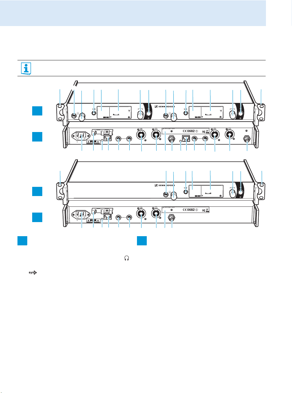
Overview of the SR 2000 IEM/SR 2050 IEM transmitter
The SR 2050 IEM twin transmitter has the same operating elements as the SR 2000 IEM transmitter. All information contained in this instruction manual refers to both transmitters.
Operating elements – front panel Operating elements – rear panel
Rack mount “ear”
Headphone output, ¼” (6.3 mm) jack socket ( )
Headphone volume control
button, backlit
Infra-red interface
Display panel, backlit in orange
Jog dial
STANDBY button with operation indication
(red backlighting), serves as the ESC (cancel)
key in the operating menu
3-pin mains socket
Cable grip for power supply DC cable
LED (yellow) for network activity indication*
LAN socket (ETHERNET RJ-45)*
Audio output left (LOOP OUT BAL L(I)),
¼” (6.3 mm) jack socket*
Audio output right (LOOP OUT BAL R(II)),
¼” (6.3 mm) jack socket*
Audio input left (BAL AF IN L(I)),
¼” (6.3 mm) jack/XLR-3 combo socket*
Audio input right (BAL AF IN R(II)),
During mono operation, the signal from the left audio
input (¼” (6.3 mm) jack/XLR-3 combo socket
transmitted
* These operating elements are available twice on the SR 2050 IEM twin transmitter and are labeled A and B respectively.
A designates the left-hand transmitter, B the right-hand one (seen from the front).
6
.
) is
¼” (6.3 mm) jack/XLR-3 combo socket*
Type plate
Antenna output (RF OUT), BNC socket*
Page 8
Product overview
PEAK
-10
0
-20
-30
-40
PEAK
-10
0
-20
-30
-40
AF I
AF II
552.300
B.Ch: 5.14
Standard -18dB
MHz
**2050**
EQ
햴
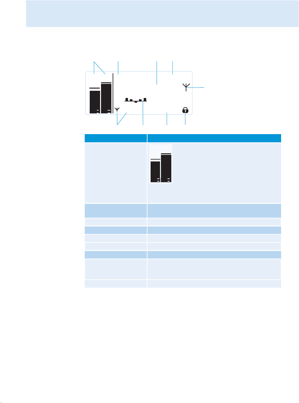
Overview of the displays
After switch-on, the transmitter displays the standard display.
Display Meaning
Audio level
“AF I” and “AF II”
(Audio Frequency)
Frequency bank and
channel
Frequency Current transmission frequency
Name Freely selectable name of the transmitter
Transmission icon RF signal is being transmitted
Transmission power Current transmission power
Equalizer setting Current equalizer setting
Input sensitivity Current input sensitivity for the audio signal available
Lock mode icon Lock mode is activated (see page 14)
PEAK
0
-10
-20
-30
-40
AF I
Current frequency bank and channel number
at the audio input sockets BAL AF IN L (I) and
BAL AF IN R (II)
Modulation of the left (AF I) and right (AF II)
PEAK
0
audio channel with peak hold function
-10
When the level displays for audio level show full
-20
deflection, the audio input level is excessively
-30
high. When the transmitter is overmodulated
-40
frequently or for extended periods of time, the
AF II
“PEAK” display is shown inverted.
During mono operation, only the “AF I” display is
shown.
7
Page 9
Putting the transmitter into operation
PEAK
-10
0
-20
-30
-40
PEA
-10
0
-20
-30
-40
AF I
AF
Putting the transmitter into operation
Setting up the transmitter on a flat surface
왘 Clean the base of the transmitter where you want to fix the device feet.
왘 Fit the device feet to the four corners of the transmitter.
왘 Place the transmitter on a flat, horizontal surface. Please note that the device feet can
leave stains on delicate surfaces.
Mounting the transmitter into a 19” rack
CAUTION! Risks when rack mounting the transmitter!
When installing the device in a closed or multi-rack assembly, please consider that, during
operation, the ambient temperature, the mechanical loading and the electrical potentials will
be different from those of devices which are not mounted into a rack.
왘 Sure that the ambient temperature within the rack does not exceed the permissible
temperature limit specified in the specifications.
왘 If necessary, provide additional ventilation.
왘 Make sure that the mechanical loading of the rack is even.
왘 When connecting to the power supply, observe the information indicated on the type
plate. Avoid circuit overloading. If necessary, provide overcurrent protection.
왘 When rack mounting, please note that intrinsically harmless leakage currents of the indi-
vidual mains units may accumulate, thereby exceeding the allowable limit value. As a
remedy, ground the rack via an additional ground connection.
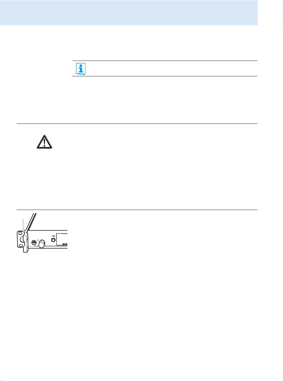
왘 Slide the transmitter into the 19” rack.
왘 Secure the rack mount “ears” to the rack using four screws (not included in the
delivery).
Do not fit the device feet when mounting the transmitter into a 19” rack.
Connecting the antennas
You have the following options:
• For professional use, we recommend connecting a remote antenna and, if necessary, using
Sennheiser antenna accessories (see next section and the chapter “Connecting several
transmitters to a remote antenna” on page 9).
• If the transmitter is to be put into operation without a large amount of installation work,
you can:
– connect the supplied rod antenna to the rear of the transmitter (see page 9) or
– use the optional GA 3030 AM antenna front mount kit (see page 9).
8
Page 10
Putting the transmitter into operation
1
4
Connecting and positioning a remote antenna
Use a remote antenna when the transmitter position is not the best antenna position for
optimum transmission. You can choose between two antennas (see “Accessories” on
page 23):
• A 2003 UHF passive directional broadband antenna
• A 1031 passive omni-directional broadband antenna
왘 Use a low-attenuation 50-Ω cable to connect the antenna to the transmitter.
왘 If possible, use a short antenna cable and as little connections as possible, since long
cables and many connectors lead to an attenuation of the antenna signal.
왘 Position the antenna in the same room in which the transmission takes place.
왘 Observe a minimum distance of 1 m between the antenna and metal objects (including
reinforced concrete walls).
You can connect several transmitters to the same remote antenna (see next section).
Connecting several transmitters to a remote antenna
To make multi-channel systems, you should use the AC 3200 antenna combiner (optional
accessory). The AC 3200 allows you to operate up to eight transmitters with a single antenna
without virtually any intermodulation.
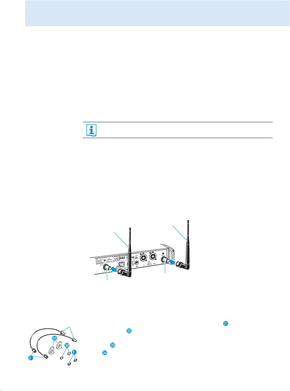
왘 Connect the AC 3200 antenna combiner to the BNC socket .
Connecting the rod antenna to the rear of the transmitter
The supplied rod antenna is suitable for all applications where the transmitter is to be put
into operation without a large amount of installation work.
왘 Connect the rod antenna to the BNC socket .
Mounting the antennas to the front of the rack
To mount the antenna connections to the front of the rack when rack mounting the transmitter, you require the GA 3030 AM antenna front mount kit (optional accessory).
The GA 3030 AM consists of:
• 2 BNC extension cables (screw-in BNC socket to BNC connector ),
• 2 antenna holders ,
•4 screws,
•2 washers ,
•2 nuts .
9
Page 11
Putting the transmitter into operation
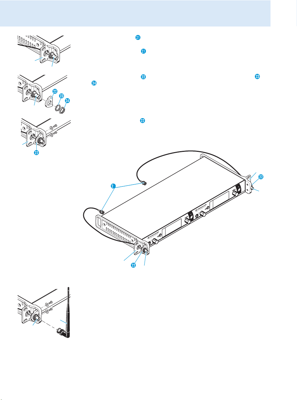
왘 Guide the BNC connector of the BNC extension cable through the hole in the rack mount
“ear” .
왘 Connect the BNC connector to the antenna output .
왘 Screw the antenna holder to the BNC socket using the supplied washer and
nut .
왘 Secure the antenna holder to the rack mount “ear” of the transmitter using two of
the supplied screws.
If you are using the SR 2050 IEM twin transmitter:
왘 Mount the second BNC extension cable in the same way.
1
왘 Slide the transmitter into the 19” rack.
왘 Connect the rod antennas to the two BNC sockets .
10
Page 12
Putting the transmitter into operation
PUSH
PUSH
Stereo Transm
L(I)
R(II)
BAL
AF IN
+ 22dBu MAX
RF OUT
ANT
DESIGNED AND MADE IN GERM
FREQ RANGE-Dw
790-865 mHz
ART NO 503841
SER NO 2518100095
FMO
IC 2099A-SR20x0
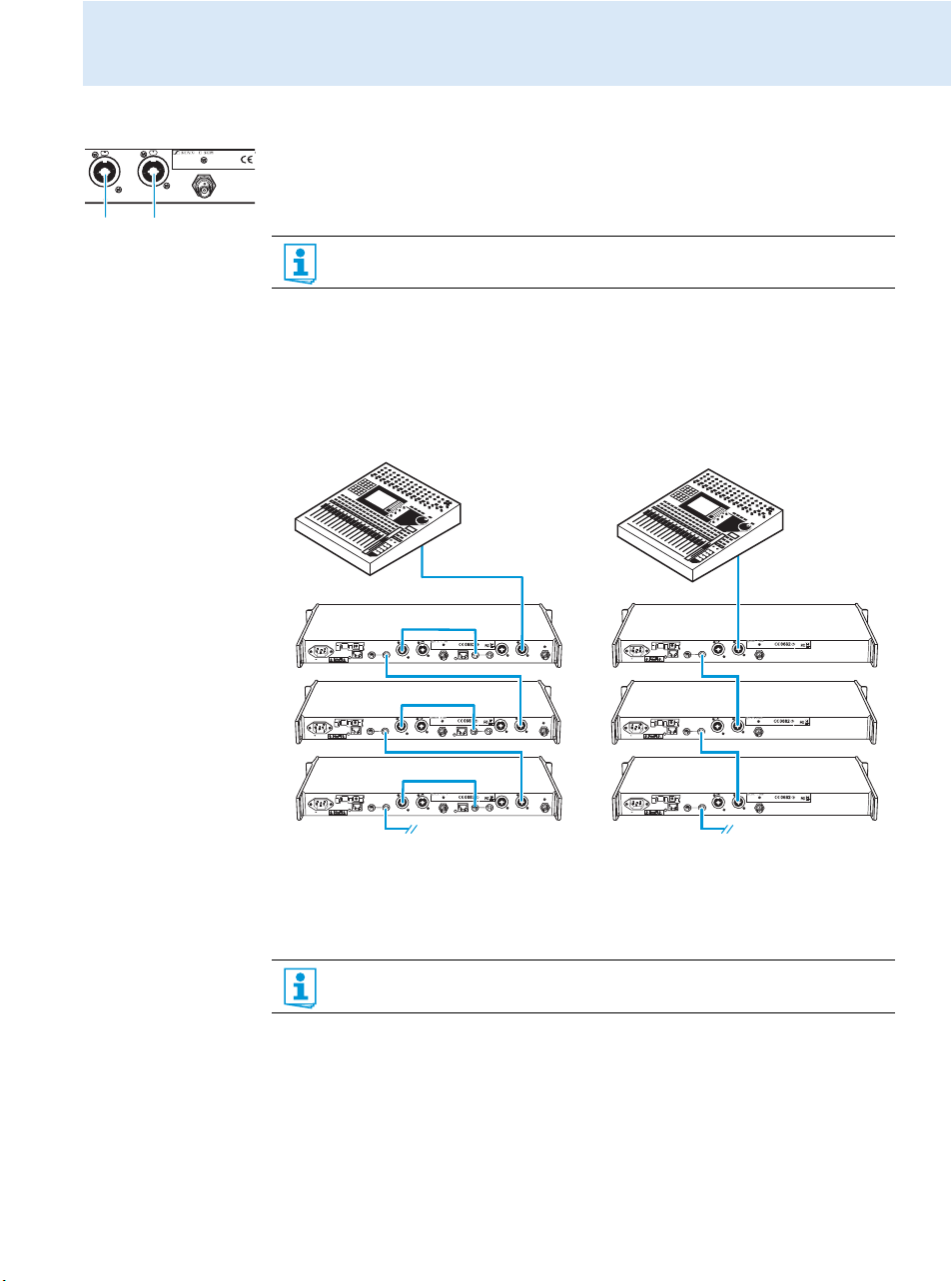
Connecting an audio source to the input sockets
왘 Use a suitable cable to connect the output of the audio source (e.g. mixing console) to the
¼” (6.3 mm) jack/XLR-3 combo socket BAL AF IN L(I) and/or BAL AF IN R(II) .
왘 Via the operating menu, adjust the transmitter’s input sensitivity. The input sensitivity is
adjusted via the “Sensitivity” menu item and is common for both inputs.
You can connect several transmitters to the same audio source (see next chapter).
Daisy chaining audio signals
The output sockets LOOP OUT BAL L and/or LOOP OUT BAL R allow you to daisy chain a
signal that is to be transmitted to all receivers from the mixing console to one transmitter
and then to the other transmitters. To do so, proceed as follows:
왘 Route a signal from the mixing console to the input socket (in this example: BAL AF IN R )
of transmitter A.
Stereo Transmitter SR 2000 IEM
PUSH
100 - 240V
50/60Hz 0.2A ETHERNET RJ-45
B
+22dBu
MAX
L(I)
R(II)
B
BAL
AF IN B
L(I)
L(I)
+ 22dBu MAX
R(II)
ETHERNET RJ-45
RF OUT
Stereo Transmitter SR 2000 IEM
PUSH
PUSH
FMO
FREQ RANGE-Dw
FMO
FREQ RANGE-Dw
IC 2099A-SR20x0
790-865 mHz
IC 2099A-SR20x0
790-865 mHz
ART NO 503841
ART NO 627945
DESIGNED AND MADE IN GERMANY
DESIGNED AND MADE IN GERMANY
SER NO 2518100095
SER NO 251810043
Loop Out B
ANT B
BAL
PUSH
Loop Out A
BAL
+22dBu
MAX
L(I)
ANT A
BAL
AF IN A
R(II)
RF OUT
R(II)
L(I)
+ 22dBu MAX
A
100 - 240V
50/60Hz 0.2A ETHERNET RJ-45
PUSH
FMO
FREQ RANGE-Dw
IC 2099A-SR20x0
790-865 mHz
ART NO 503841
DESIGNED AND MADE IN GERMANY
SER NO 2518100095
Loop Out
ANT
BAL
B
+22dBu
BAL
MAX
AF IN
L(I)
L(I)
+ 22dBu MAX
R(II)
R(II)
RF OUT
A
100 - 240V
50/60Hz 0.2A ETHERNET RJ-45
100 - 240V
50/60Hz 0.2A ETHERNET RJ-45
B
+22dBu
MAX
L(I)
R(II)
Loop Out B
BAL
B
+22dBu
MAX
L(I)
R(II)
B
BAL
AF IN B
L(I)
L(I)
+ 22dBu MAX
R(II)
ETHERNET RJ-45
RF OUT
Stereo Transmitter SR 2000 IEM
PUSH
PUSH
FMO
FREQ RANGE-Dw
FMO
FREQ RANGE-Dw
IC 2099A-SR20x0
790-865 mHz
IC 2099A-SR20x0
790-865 mHz
ART NO 503841
ART NO 627945
DESIGNED AND MADE IN GERMANY
DESIGNED AND MADE IN GERMANY
SER NO 2518100095
SER NO 251810043
ANT B
B
BAL
AF IN B
L(I)
L(I)
+ 22dBu MAX
R(II)
ETHERNET RJ-45
RF OUT
Stereo Transmitter SR 2000 IEM
PUSH
PUSH
FMO
FREQ RANGE-Dw
FMO
FREQ RANGE-Dw
IC 2099A-SR20x0
790-865 mHz
IC 2099A-SR20x0
790-865 mHz
ART NO 503841
ART NO 627945
DESIGNED AND MADE IN GERMANY
DESIGNED AND MADE IN GERMANY
SER NO 2518100095
SER NO 251810043
Loop Out B
ANT B
BAL
PUSH
Loop Out A
BAL
+22dBu
MAX
L(I)
Loop Out A
BAL
+22dBu
MAX
L(I)
ANT A
BAL
AF IN A
R(II)
RF OUT
R(II)
L(I)
+ 22dBu MAX
B
PUSH
ANT A
BAL
AF IN A
R(II)
RF OUT
R(II)
L(I)
+ 22dBu MAX
C
100 - 240V
50/60Hz 0.2A ETHERNET RJ-45
100 - 240V
50/60Hz 0.2A ETHERNET RJ-45
Loop Out
BAL
B
+22dBu
MAX
L(I)
R(II)
Loop Out
BAL
B
+22dBu
MAX
L(I)
R(II)
Stereo Transmitter SR 2000 IEM
PUSH
PUSH
FMO
FREQ RANGE-Dw
IC 2099A-SR20x0
790-865 mHz
ART NO 503841
DESIGNED AND MADE IN GERMANY
SER NO 2518100095
ANT
BAL
AF IN
L(I)
+ 22dBu MAX
R(II)
RF OUT
Stereo Transmitter SR 2000 IEM
PUSH
PUSH
FMO
FREQ RANGE-Dw
IC 2099A-SR20x0
790-865 mHz
ART NO 503841
DESIGNED AND MADE IN GERMANY
SER NO 2518100095
ANT
BAL
AF IN
L(I)
+ 22dBu MAX
R(II)
RF OUT
B
C
왘 Connect the output socket LOOP OUT BAL R of transmitter A to the input socket
BAL AF IN R of transmitter B.
왘 Connect the output socket LOOP OUT BAL R of transmitter B to the input socket
BAL AF IN R of transmitter C.
왘 Repeat for the other transmitters.
The AF output sockets LOOP OUT BAL L and/or LOOP OUT BAL R will work only
when the transmitter is switched on and powered.
11
Page 13
Putting the transmitter into operation
ETHERNET RJ-45
B
RF OUT
ANT B
DESIGNED AND MADE IN GERMANY
FREQ RANGE-Dw
790-865 mHz
ART NO 627945
SER NO 251810043
FMO
IC 2099A-SR20x0
Stereo Transmitter SR 2000 IEM
DESIGNED AND MADE IN GERMANY
FREQ RANGE-Dw
790-865 mHz
ART NO 503841
SER NO 2518100095
FMO
IC 2099A-SR20x0
L(I)
R(II)
+22dBu
MAX
Loop Out A
BAL
ETHERNET RJ-45
RF OUT
ANT B
DESIGNED AND MADE IN GERMANY
FREQ RANGE-Dw
790-865 mHz
ART NO 627945
SER NO 251810043
FMO
IC 2099A-SR20x0
Stereo Transmitter SR 2000 IEM
DESIGNED AND MADE IN GERMANY
FREQ RANGE-Dw
790-865 mHz
ART NO 503841
SER NO 2518100095
FMO
IC 2099A-SR20x0
L(I)
R(II)
+22dBu
MAX
Loop Out A
BAL
50/60Hz 0.2A ETHERNET RJ-45
B
100 - 240V
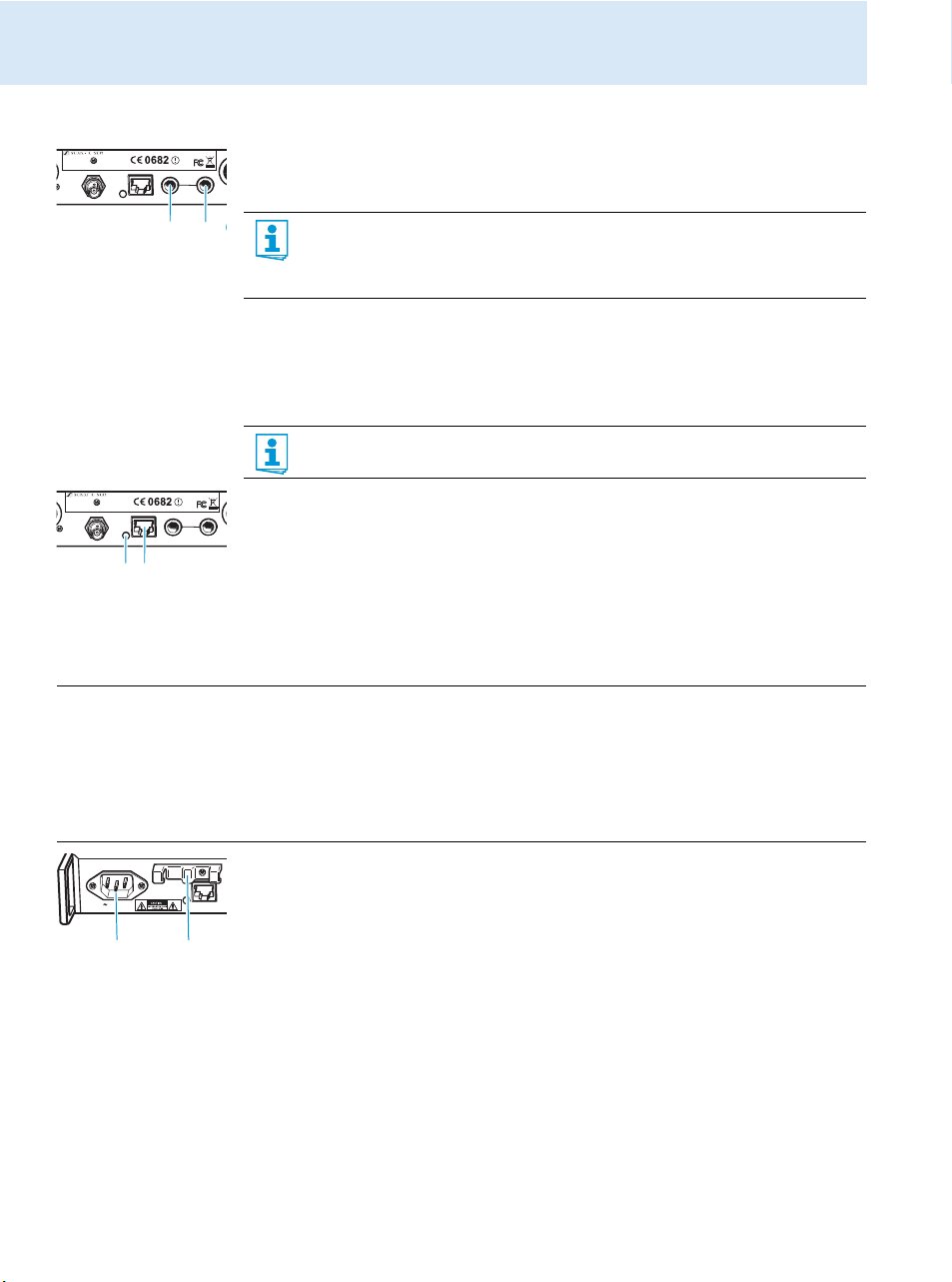
Connecting devices to the output sockets
왘 Use a suitable cable to connect the audio input of a device (e.g. a mixing console or an
additional SR 2000 IEM or SR 2050 IEM) to the output socket LOOP OUT BAL L(I) and/
or LOOP OUT BAL R(II) (see preceding chapter).
Connecting transmitters in a network
You can connect several transmitters in a network. The transmitters are remote controlled via
a PC running the “Wireless Systems Manager” (WSM) software. This software will assist in
the quick and safe configuration of multi-channel systems.
왘 Connect a standard network cable (at least Cat 5) to the LAN socket of the transmitter.
왘 Connect your transmitters to an Ethernet switch.
왘 Connect a PC to the Ethernet switch.
When a transmitter is properly connected to the Ethernet switch or the PC, the yellow
LED at the rear of the transmitter lights up.
For further information on network operation, refer to page 22.
The signal received from the AF input sockets BAL AF IN L(I) and BAL AF IN R(II)
is actively buffered and then routed to the output sockets LOOP OUT BAL L(I) and
LOOP OUT BAL R(II) . The AF output sockets will therefore work only when the trans-
mitter is switched on and powered.
The “Wireless Systems Manager” (WSM) software can be downloaded from the
corresponding product page on our website at www.sennheiser.com.
12
Connecting the mains cable
CAUTION! Damage due to electric current!
If you connect the transmitter to an unsuitable power supply, this can cause damage to the
device.
왘 Use the supplied mains cable to connect the transmitter to the mains (100 to 240 V AC,
50 or 60 Hz).
왘 Ensure a reliable mains ground connection of the transmitter – especially when you are
using multi-outlet power strips or extension cables.
왘 Pass the mains cable through the cable grip .
왘 Connect the mains cable to the mains socket .
왘 Plug the mains plug into the wall socket.
Page 14
Using the transmitter
0**
Using the transmitter
To establish a transmission link, proceed as follows:
1. Switch the transmitter on (see below).
2. Switch the
The transmission link is established.
If you cannot establish a transmission link between transmitter and receiver:
왘 Make sure that transmitter and receiver are set to the same frequency bank and to the
same channel.
왘 If necessary, read the chapter “If a problem occurs ...” on page 24.
Switching the transmitter on/off
To switch the transmitter on (online operation):
To switch the transmitter to standby mode:
왘 If necessary, deactivate the lock mode (see page 14)
EK 2000 IEM
receiver on (see the instruction manual of the receiver).
It is vital to observe the notes on frequency selection on page 22.
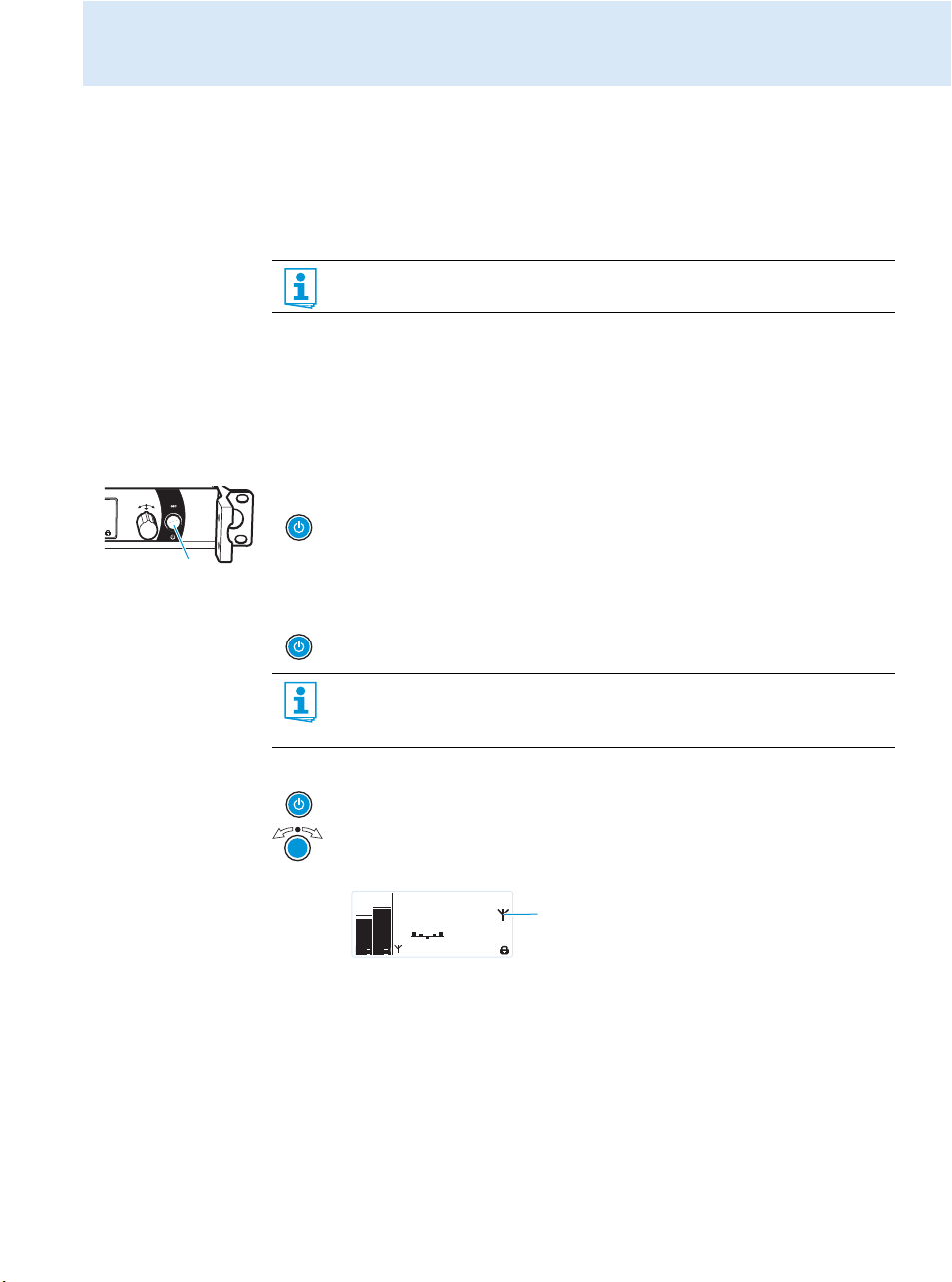
왘 Briefly press the STANDBY button .
The transmitter switches on and the standard display appears.
The transmitter transmits an RF signal and the transmission icon
is displayed.
왘 Keep the STANDBY button pressed until “OFF” appears on the display panel.
The display panel switches off.
When in the operating menu, pressing the STANDBY button will cancel your entry
(ESC function) and return you to the standard display.
The STANDBY button is backlit in red both during operation and in standby mode.
To switch the transmitter on and to deactivate the RF signal on switch-on (offline operation):
왘 Press the STANDBY button until “RF Mute On?” appears on the display panel.
왘 Press the jog dial.
The transmission frequency is displayed but the transmitter does not transmit an
RF signal. The transmission icon
PEAK
PEAK
B.Ch: 5.14
0
0
-10
-10
-20
-20
-30
-30
EQ
-40
-40
Standard -18dB
AF I
AF II
552.300
**2000**
MHz
is not displayed
.
To completely switch the transmitter off:
왘 Disconnect the transmitter from the mains by unplugging the mains plug from the wall
socket.
The backlighting of the STANDBY button goes off.
13
Page 15
Using the transmitter
Deactivating the lock mode temporarily
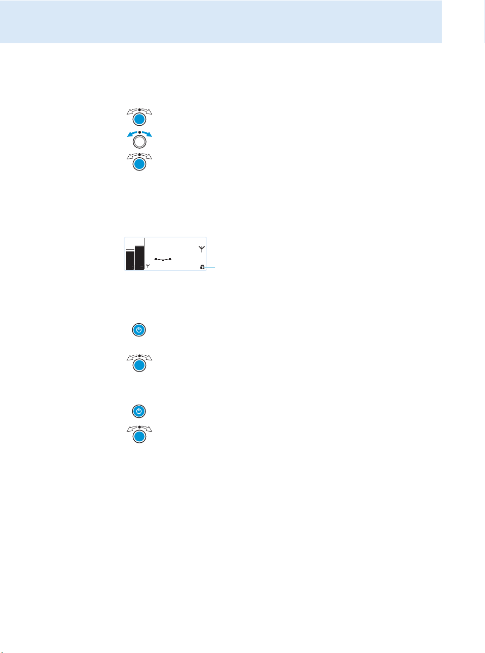
You can activate or deactivate the automatic lock mode via the “Auto Lock” menu item. If the
lock mode is activated, you have to temporarily deactivate it In order to be able to operate
the transmitter:
왘 Press the jog dial.
“Locked” appears on the display panel.
왘 Tur n t he jo g dial.
“Unlock?” appears on the display panel.
왘 Press the jog dial.
The lock mode is temporarily deactivated.
– When you are in the operating menu, the lock mode remains deactivated until
you exit the operating menu.
– When the standard display is shown, the lock mode is automatically activated
after 10 seconds.
The lock mode icon flashes prior to the lock mode being activated again.
PEAK
PEAK
B.Ch: 5.14
0
0
-10
-10
-20
-20
-30
-30
EQ
-40
-40
Standard -18dB
AF I
AF II
552.300
**2000**
MHz
Activating/deactivating the RF signal
To deactivate the RF signal:
왘 When the standard display is shown on the display panel, press the STANDBY
button.
“RF Mute On?” appears on the display panel.
왘 Press the jog dial.
The RF signal is deactivated. “RF Mute” flashes in alternation with the standard
display and the display is backlight in red.
To activate the RF signal:
왘 Press the STANDBY button.
“RF Mute Off?” appears on the display panel.
왘 Press the jog dial.
The RF signal is activated and the display backlighting changes from red to
orange.
To deactivate the RF signal on switch-on:
왘 See “offline operation” on page 13.
14
Adjusting the audio channels
Via the “Mode” menu item, you can adjust the audio channels.
왘 Select “Stereo” if you want to transmit two separate audio signals on channel I and
channel II (e.g. channel I = audio signal of the presenter/musician, channel II = sum of all
audio signals).
This allows the presenter/musician to adjust the balance between the left and right stereo
signal on his receiver.
왘 Select “Mono” if you only want to transmit an audio signal on one channel. In this case,
the signal from the left audio input
BAL AF IN L (I)
is transmitted.
Page 16
During mono operation, you have to deactivate the pilot tone evaluation on the
Stereo Transmitter SR 2000 IEM
PEAK
-10
0
-20
-30
-40
PEAK
-10
0
-20
-30
-40
AF I
AF II
EK 2000 IEM receiver in order to ensure that your receiver outputs the same signal
on channel I and II.
Monitoring the audio signal via headphones
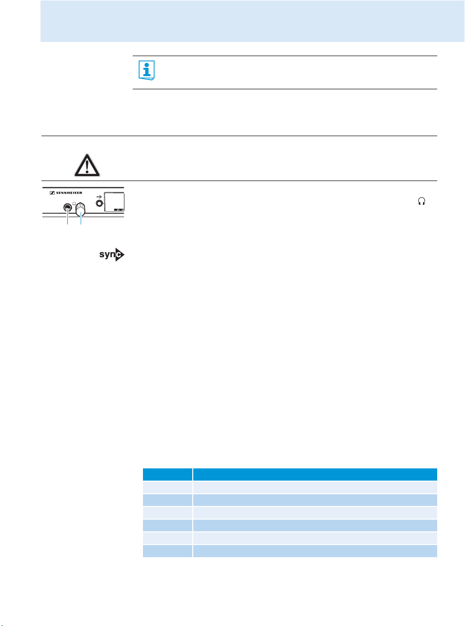
You can monitor the audio signal via the headphone output .
CAUTION! Danger of hearing damage!
Listening at high volume levels for long periods can lead to permanent hearing defects.
왘 Set the headphone volume control to the minimum position before putting the head-
phones on.
왘 Set the headphone volume control to the minimum position.
왘 Connect headphones with a ¼” (6.3 mm) stereo jack plug to the headphone output .
왘 Gradually increase the volume and monitor the audio signal with the lowest possible
volume.
Synchronizing transmitters and EK 2000 IEM receivers via the infra-red interface
Synchronization allows you to quickly and easily transfer transmitter and receiver settings
from one device to the other, especially if you want to configure a multi-channel system.
There are two transfer directions:
1. Easy Setup Sync: Transfer from the receiver to one or several transmitters
Once you have performed a frequency preset scan with your receiver, you can use the
Easy Setup Sync function to transfer unused frequency presets from the receiver to the
transmitters via the infra-red interface. In order to configure a multi-channel system, you
use the diversity receiver to transfer the first unused channel from the selected frequency
bank to the first transmitter and the next unused channel to the second transmitter and
so on, thus ensuring that all transmitters of a multi-channel system operate on suitable
frequencies.
2. Sync: Transfer from a transmitter to a receiver
Once you have selected and set the desired receiver settings on the transmitter (either
manually or using the Easy Setup Sync function), you transfer these settings to a receiver.
This configures the receiver and establishes a transmission link between transmitter and
receiver.
Via the “Sync Settings” submenu, you can adjust the receiver parameters listed below and
activate or deactivate their transfer to an EK 2000 IEM receiver.
Setting Transferred receiver parameter
“Balance” Current balance setting (“−15”/“+15”)
“Squelch” Current squelch setting (“Off”, “5 dB” ... “25 dB”)
“Mode” Current audio mode setting (“Stereo”/“Focus”)
“High Boost” Current treble boost setting (“flat”/“High boost”)
“Auto Lock” Current lock mode setting (“active”/“inactive”)
“Limiter” Current limiter setting (“−18 dB”, “−12 dB”, “−6dB”, “Off”)
Using the transmitter
15
Page 17
Using the transmitter
OFF
2
4
6
PHONES
OFF
2
4
6
PHONES
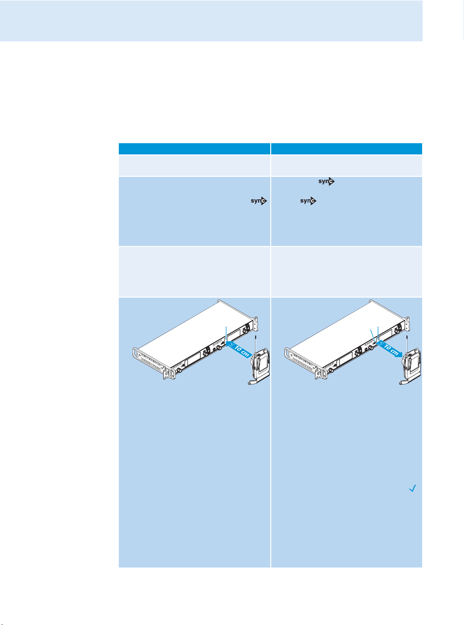
When carrying out the Sync function, the transmitter’s current frequency bank and
channel setting as well as the receiver parameters adjusted via the “Sync Settings”
submenu are transferred to the EK 2000 IEM receiver via the infra-red interface.
Carrying out an Easy Setup Sync or a Sync function
The following assumes that you are using the Easy Setup Sync function for setting up a multichannel system. You can also you the Easy Setup Sync function for establishing a transmis-
sion link between one transmitter and one
EK 2000 IEM
Easy Setup Sync Sync
왘 Switch all transmitters and one diversity
receiver on.
왘 On all transmitters, call up the “Easy
Setup” menu item.
The text “Easy Setup Sync” and the
icon appear on the display panels of the
transmitters.
The RF signal of the transmitters is automatically deactivated.
왘 Use your diversity receiver to perform a
frequency preset scan and select a
channel within a frequency bank with a
sufficient number of unused channels (see
the instruction manual of the receiver).
receiver.
왘 Switch your transmitter and your
diversity receiver on.
왘 Press the button on the trans-
mitter.
The icon appears on the display
panels of the transmitter.
–
16
왘 Place the infra-red interface of the
receiver (see the instruction manual of
the receiver) in front of the infra-red
interface of the first transmitter.
The next unused frequency preset is
transferred from the receiver to the
transmitter.
As soon as the transfer is completed, the
display panel of the transmitter displays
the numbers of the transferred frequency bank and channel.
Please note that the transmitter does not
automatically store the frequency bank
and channel setting.
왘 Place the infra-red interface of the
receiver (see the instruction manual of
the receiver) in front of the infra-red
interface of your transmitter.
The parameters adjusted via the “Sync
Settings” menu item are transferred
from the transmitter to the receiver
In addition, the current frequency bank
and channel setting is transferred.
When the transfer is completed, “ ”
appears on the display panel of the transmitter. The transmitter then switches
back to the standard display.
The transferred parameters are automatically adjusted and stored by the receiver.
The transmission link between transmitter and receiver is now established.
.
Page 18
Easy Setup Sync Sync
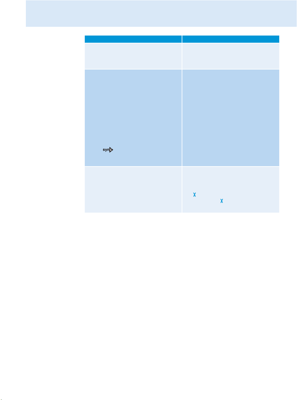
왘 Place the infra-red interface of the diver-
sity receiver in front of the infra-red
interfaces of the remaining transmitters,
one after the other.
왘 Store the frequency bank and channel
setting by pressing the jog dial on your
transmitters. You can carry out the Sync
function (see right-hand column) at a
later time to establish a transmission link
between transmitters and receivers.
OR:
왘 Immediately synchronize your receivers
with your transmitters by carrying out the
Sync function (see right-hand column).
This establishes a transmission link
between transmitters and receivers.
The icon in the left lower corner of
the transmitter display indicates that the
Sync function can be carried out.
–
To cancel the transfer:
왘 Press the STANDBY button on the trans-
Using the transmitter
–
–
mitter.
“ ” appears on the display panel of the
transmitter. “ ” also appears if no suitable receiver was found.
17
Page 19
Using the operating menu
Sensitivity
Easy Setup
Mode
Frequency Preset
Name
Equalizer
AutoLock
Advanced
Exit
Main menu
“Menu”
Tune
Sync Settings
RF Power
Warnings
LCD Contrast
Reset
IP-Address
Software Revision
Exit
Extended menu
“Advanced Menu”
AF Peak
RF Mute
Exit
“Warnings”
Balance
Squelch
Mode
High Boost
Auto Lock
Limiter
Exit
“Sync Settings”
Using the operating menu
The buttons
Button Function of the button
Press the STANDBY
button
Press the jog dial • Changes from the standard display to the operating menu
Turn the jog dial • Changes to the next/previous menu item
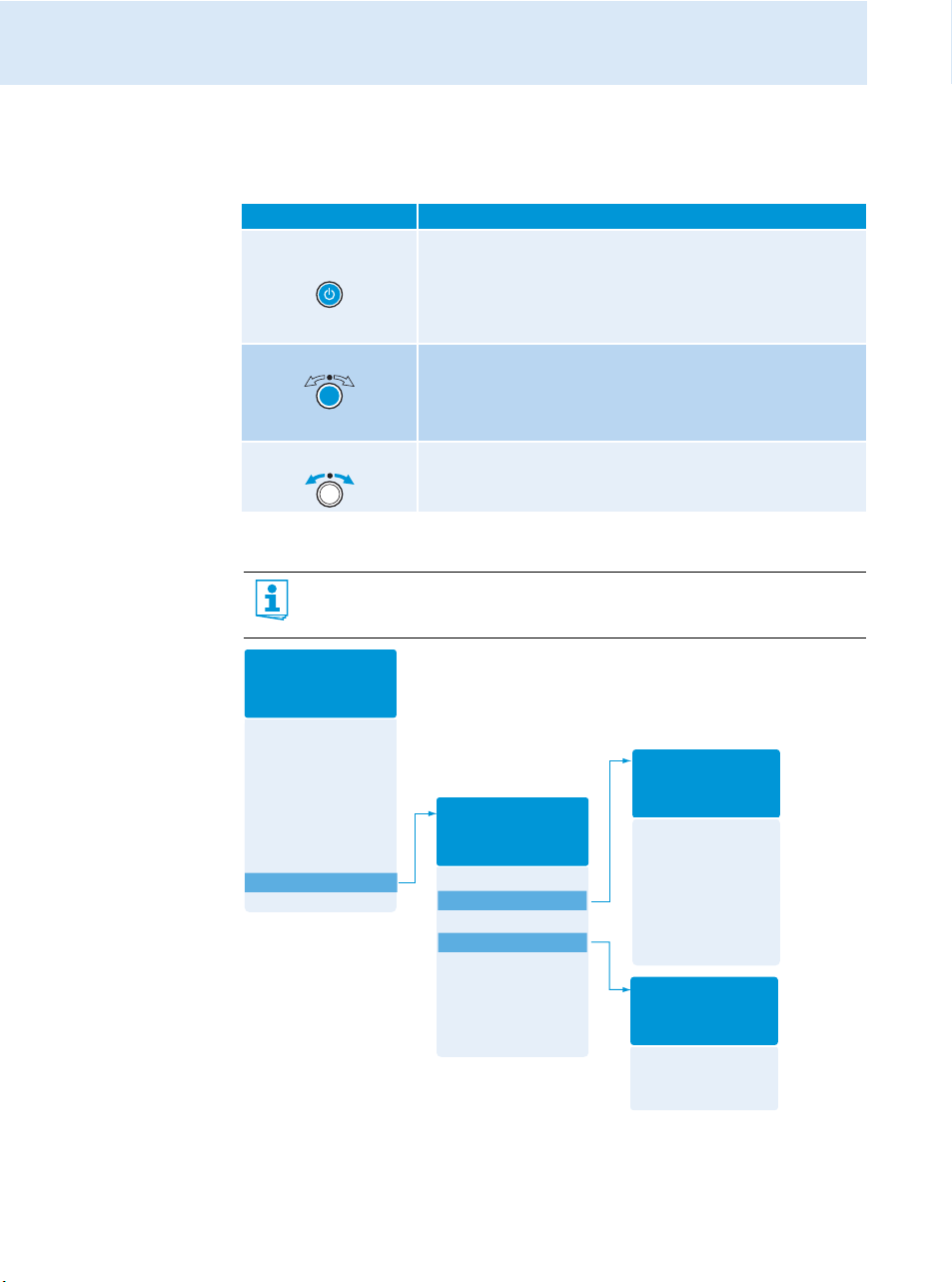
Overview of the operating menu
For more detailed information on the operating menu, refer to the instruction
manual of the SR 2000 IEM/SR 2050 IEM which can be downloaded from the
SR 2000 IEM/SR 2050 IEM product page at www.sennheiser.com.
• Switches the transmitter on and off
• Cancels the entry and returns to the standard display
(ESC function)
• Activates/deactivates the RF signal
(special function, see page 14)
• Calls up a menu item
• Enters a submenu
• Stores the settings and returns to the operating menu
• Changes the setting of a menu item
18
Page 20

Using the operating menu
When the standard display is shown on the display panel, you can get into the main menu by
pressing the jog dial. The extended menu “Advanced Menu” and the other menus can be
accessed via the corresponding menu items.
Display Function of the menu item
Main menu “Menu”
Sensitivity Adjusts the input sensitivity
Easy Setup Deactivates the RF signal and activates Easy Setup Sync (see page 15)
Mode Selects mono or stereo operation
Frequency Preset Changes the frequency bank and the channel
Name Enters the transmitter name
Equalizer Changes the frequency response of the output signal using a graphic
equalizer
AutoLock Activates/deactivates the automatic lock mode
Advanced Calls up the extended menu “Advanced Menu”
Exit Exits the operating menu and returns to the standard display
Extended menu “Advanced Menu”
Tune Sets the transmission frequencies for the frequency banks “U1” to
“U6”
Special function: Sets a channel and a transmission frequency for the
frequency banks “U1” to “U6”:
왘 Select this menu item and call it up by pressing the jog dial until
the channel selection appears.
Sync Settings Adjusts the receiver parameters to be transferred to the receiver and
activates/deactivates the transfer (see table on page 15)
RF Power Adjusts the transmission power
Warnings Calls up the submenu “Warnings”
LCD Contrast Adjusts the contrast of the display panel
Reset Resets the transmitter
IP-Address Adjusts the IP address of the transmitter
Software Revision Displays the current software revision
Exit Exits the extended menu “Advanced Menu” and returns to the main
menu
Submenu “Warnings”
Activates/deactivates warnings (color change and warning messages):
AF Peak Audio overmodulation
RF Mute RF signal is deactivated
Exit Exits the submenu “Warnings” and returns to the extended menu
“Advanced Menu”
19
Page 21
Using the operating menu
Squelch
Easy Setup
Frequency Preset
Name
AF Out
Equalizer
Auto Lock
Advanced
Exit
Menu
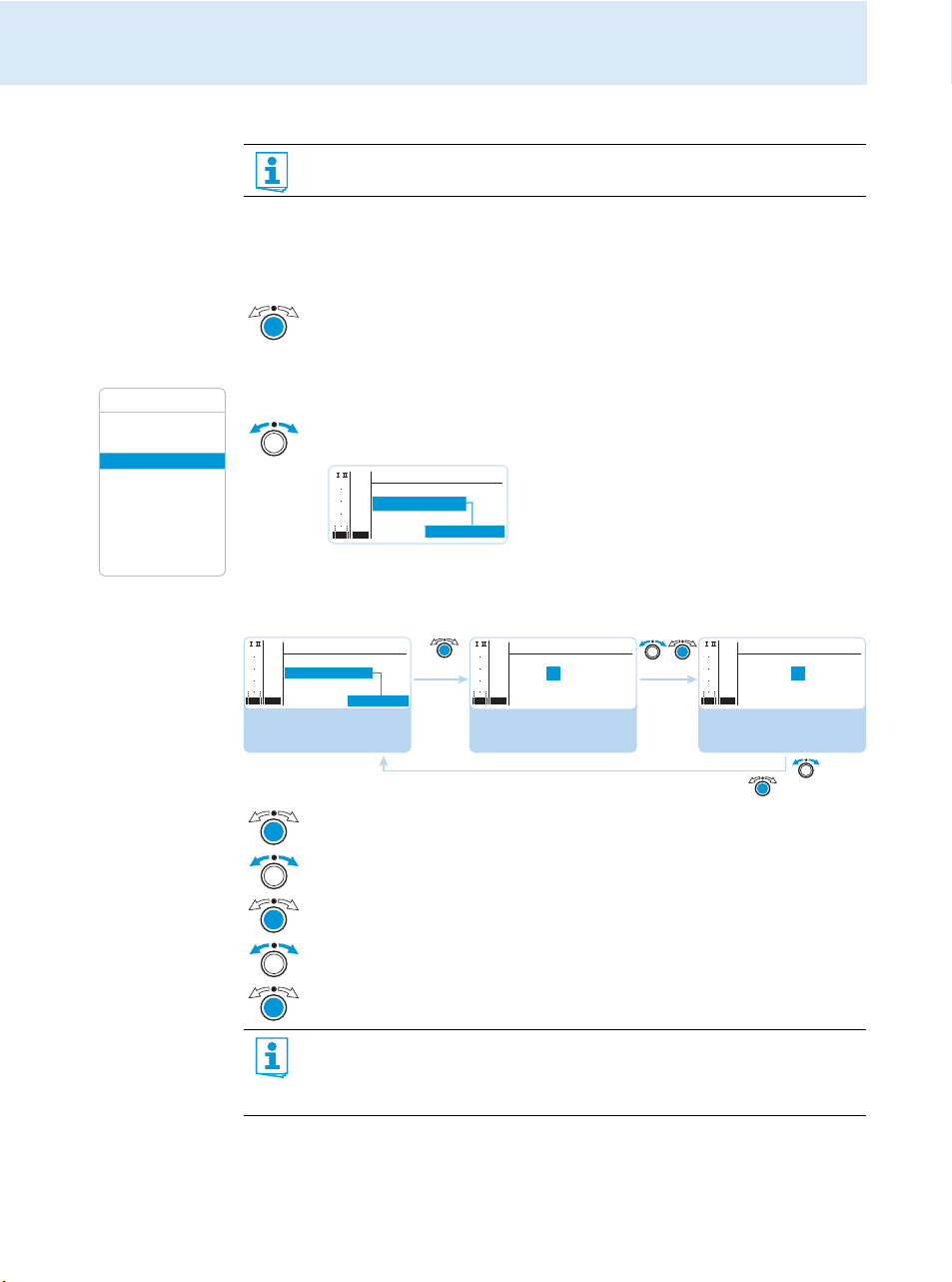
Working with the operating menu
If the lock mode is activated, you have to deactivate it In order to be able to work
with the operating menu (see page 14).
By way of example of the “Frequency Preset” menu, this section describes how to use the
operating menu.
Changing from the standard display to the operating menu
왘 Press the jog dial.
The standard display is replaced by the main menu. The last selected menu item
is displayed.
Selecting a menu item
왘 Turn the jog dial to change to the “Frequency Preset” menu item.
The current setting of the selected menu item is displayed:
PEAK
Menu
040
Easy Setup
-10
30
-20
Frequency Preset
20
-30
Name
10
-40
AF
RF
Changing and storing settings
PEAK
Menu
040
-10
Easy Setup
30
-20
Frequency Preset
20
-30
10
Name
-40
AF
RF
Call up “Frequency
Preset”
B.Ch: 5.14
B. Ch: 1. 1
PEAK
040
-10
30
-20
20
-30
10
-40
AF
RF
Select the frequency
bank and confirm
Frequency Preset
B.Ch: 5.14
543.000 MHz
PEAK
Frequency Preset
040
-10
30
-20
B.Ch: 5.14
20
-30
10
-40
AF
RF
543.000 MHz
Select the channel;
store the setting
20
“Stored”
왘 Press the jog dial to call up the menu item.
왘 Turn the jog dial to set the frequency bank.
왘 Press the jog dial to confirm your selection.
왘 Turn the jog dial to set the channel.
왘 Press the jog dial to store the setting.
By briefly turning the jog dial to the left or right, the display jumps either forwards
or backwards to the next menu item or setting. If you turn the jog dial to the left or
right and hold it in this position, the display cycles continuously (“fast search”
function).
Page 22
Canceling an entry
Squelch
Easy Setup
Frequency Preset
Name
AF Out
Equalizer
Auto Lock
Advanced
Exit
Menu
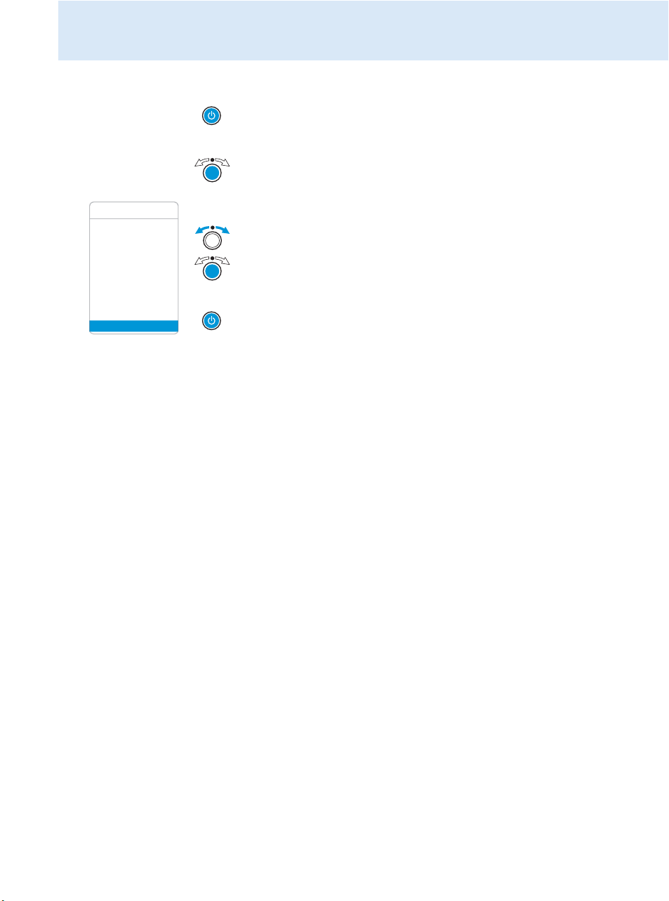
왘 Press the STANDBY button to cancel the entry.
The standard display appears on the display panel.
To return to the last edited menu item:
왘 Press the jog dial repeatedly until the last edited menu item appears.
Exiting a menu item
왘 Change to the “Exit” menu item.
왘 Confirm your selection.
You return to the next higher menu level.
To directly return to the standard display:
왘 Press the STANDBY button.
Using the operating menu
21
Page 23
Synchronizing the transmitter with an EK 2000 IEM receiver
Stereo Transmitter SR 2050 IEM
Stereo Transmitter SR 2050 IEM
Stereo Transmitter SR 2050 IEM
Synchronizing the transmitter with an EK 2000 IEM
receiver
When synchronizing your transmitter with an EK 2000 IEM receiver, please observe the
following:
왘 Only use a transmitter and a receiver from the same frequency range (see the
type plate on the transmitter and the receiver).
왘 Make sure that the desired frequencies are listed in the enclosed frequency infor-
mation sheet.
왘 Make sure that the desired frequencies are approved and legal in your country
and, if necessary, apply for an operating license.
Synchronizing the transmitter with an EK 2000 IEM receiver – individual operation
Upon delivery, transmitter and receiver are synchronized with each other. If, however, you
cannot establish a transmission link between transmitter and receiver, you have to synchronize the channels of the devices:
왘 Carry out the Easy Setup Sync function and then the Sync function (see
Alternatively, you can set the channel on the transmitter manually:
왘 Make sure that you set the transmitter to the same frequency bank and the same channel
as the receiver.
Synchronizing transmitters with EK 2000 IEM receivers – multi-channel operation
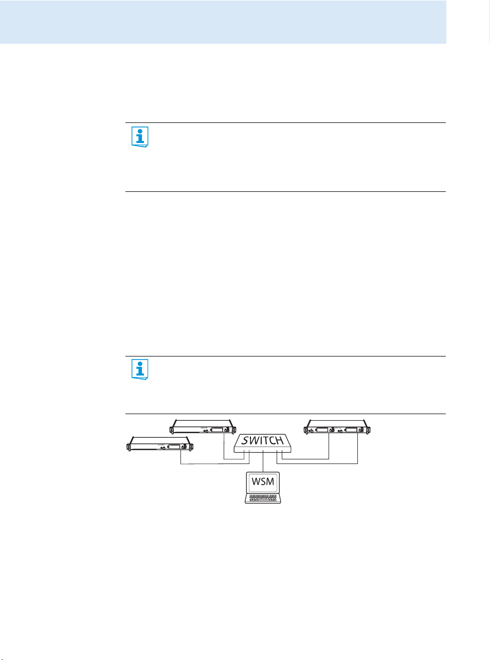
Network operation
using the WSM
In multi-channel operation, the transmitters are remote controlled via a PC running the
“Wireless Systems Manager” (WSM) software.
Advantages of controlling the transmitters via the “Wireless Systems Manager”
(WSM) software:
• Detailed overview of all transmission and receiving channels
• Remote control of all transmitters in the network
• Combination of transmitters of different frequency ranges (see page 4).
page 16)
.
Operation without
22
network
왘 Connect your transmitters and your PC in a network (see page 12).
왘 Switch your transmitters and your PC on.
왘 Launch the “Wireless Systems Manager” (WSM) software.
왘 To set up your multi-channel system, proceed as described in the instruction manual of
the “Wireless Systems Manager” (WSM) software.
왘 Carry out the Easy Setup Sync function and then, for each transmission link, the Sync
function (see
page 16).
Page 24
Using freely selectable transmission frequencies
You can also freely select the frequencies and store these frequencies in the frequency banks
“U1” to “U6”.
If you want to use the frequency banks “U1” to “U6”:
왘 Make sure to use transmitters and receivers from the same frequency range (see page 4
and the type plates of the devices).
To ensure that the desired frequencies are intermodulation-free:
왘 Contact your Sennheiser partner (see www.sennheiser.com).
왘 Set each transmitter to the same frequency bank.
왘 On one of the transmitters, select a channel within this frequency bank (see page 19).
왘 Assign this channel one of the calculated transmission frequencies (see page 19).
왘 Synchronize a receiver with your transmitter ( , see
OR
왘 Manually set the receiver to the same frequency bank, channel and frequency that you set
on the transmitter.
왘 Repeat for the remaining transmitters and receivers as described above.
Cleaning the transmitter
CAUTION! Liquids can damage the electronics of the transmitter!
Liquids entering the housing of the device can cause a short-circuit and damage the
electronics.
왘 Keep all liquids away from the transmitter.
왘 Before cleaning, disconnect the device from the mains.
왘 Use a slightly damp cloth to clean the device from time to time. Do not use any solvents
or cleansing agents.
Cleaning the transmitter
page 16
)
Accessories
Cat. No.
004368 GA 3030 AM antenna front mount kit
502048 AC 3200 antenna combiner
500887 A 5000 CP circularly polarized broadband antenna
003658 A 2003 directional broadband antenna
004645 A 1031 omni-directional broadband antenna
087969 Antenna daisy-chain cable, 50 Ω, BNC, 0.25 m
002324 GZL 1019-A1 coaxial cable, type RG 58, BNC to BNC, 1 m
Accessory
23
Page 25

If a problem occurs ...
24
If a problem occurs ...
Problem Possible cause Possible solution
Transmitter cannot be
operated, “Locked”
appears on the display
panel
No operation indication No mains connection Check the connections of the
No RF signal at the
receiver
Very weak RF signal at
the receiver
RF signal available,
no audio signal at the
receiver
Audio signal has a high
level of background
noise
Audio signal is distorted If “AF PEAK” additionally
If a problem occurs that is not listed in the above table or if the problem cannot be solved with
the proposed solutions, please contact your local Sennheiser partner for assistance.
To find a Sennheiser partner in your country, search at www.sennheiser.com under “Service
& Support”.
Lock mode is activated Deactivate the lock mode
Transmitter and receiver are
not on the same channel
If “RF Mute” additionally
appears on the transmitter
display:
RF signal is deactivated
Transmission range is
exceeded
Receiver’s squelch threshold is
adjusted too high
No input signal at the
transmitter
Very low input signal Check the audio level on the
Transmitter sensitivity is
adjusted too low
appears on the transmitter
display:
transmitter sensitivity is
adjusted too high
Receiver’s audio output level
is adjusted too high
(see page 14 and page 18).
mains cable (see page 12).
Synchronize the transmitter
with the receiver (see
page 15).
Activate the RF signal
(see page 14).
Check the squelch threshold
setting on the receiver.
Reduce the distance between
receiver and transmitter.
Increase the transmission
power (see page 19).
Reduce the squelch threshold
(see the instruction manual of
the receiver).
Reposition the antennas.
Check the audio level on
the transmitter display
(see page 7).
transmitter display (see
page 7), increase the level of
the input signal or adjust the
input sensitivity (see page 19).
Adjust the transmitter sensitivity correctly (see page 19).
Adjust the transmitter
sensitivity correctly.
Reduce the audio output level
(see the instruction manual of
the receiver).
Page 26

Specifications
Specifications
RF characteristics
Frequency ranges 516–558, 558–626, 626–698, 718–790, 790–865 MHz
(Aw to Dw, Gw, see page 4)
Transmission frequencies up to 3,000 frequencies, tuneable in steps of 25 kHz
20 frequency banks, each with up to 32 factory-preset channels
6 frequency banks, each with up to 32 user programmable
channels
Switching bandwidth up to 75 MHz
Frequency stability ±10 ppm (–10°C to +55°C)
Antenna output BNC socket, 50 Ω
RF output power at 50 Ω typ. 10/30/50 mW (Low/Standard/High), switchable
AF characteristics
Modulation wideband FM stereo (MPX pilot tone)
Compander system Sennheiser HDX
Nominal/peak deviation ±24 kHz/±48 kHz
MPX pilot tone (frequency/deviation) 19 kHz/±5 kHz
AF frequency response 25 Hz to 15 kHz
AF input
Max. input level +22 dBu
THD
(at 1 kHz and nominal deviation) < 0.9%
Signal-to-noise ratio at nominal load
and peak deviation > 90 dB
AF output LOOP OUT BAL L (I)/LOOP OUT BAL R (II) ¼’’ (6.3 mm) stereo jack socket, balanced
BAL AF IN L (I)/BAL AF IN R (II)
2 x
XLR-3/
¼’’ (6.3 mm) jack combo socket,
electronically balanced
Overall device
Temperature range –10°C to + 55°C
Power supply 100–240 V~
Current consumption SR 2000: 0.1 A
Dimensions approx. 217 x 483 x 43 mm
Weight
SR 2050: 0.2 A
SR 2000: approx. 2500 g
SR 2050: approx. 2700 g
In compliance with
Europe
EMC EN 301489-1/-9
Radio EN 300422-1/-2, EN 300454-1/-2
Safety EN 60065
25
Page 27
Manufacturer Declarations
Approved by
Canada Industry Canada RSS 123
and 2099A-SR2050
IC: 2099A-SR200
li
mited to 806 MHz
USA FCC-Part 74
li
mited to 698 MHz
0
FCC-ID: DMOSR200
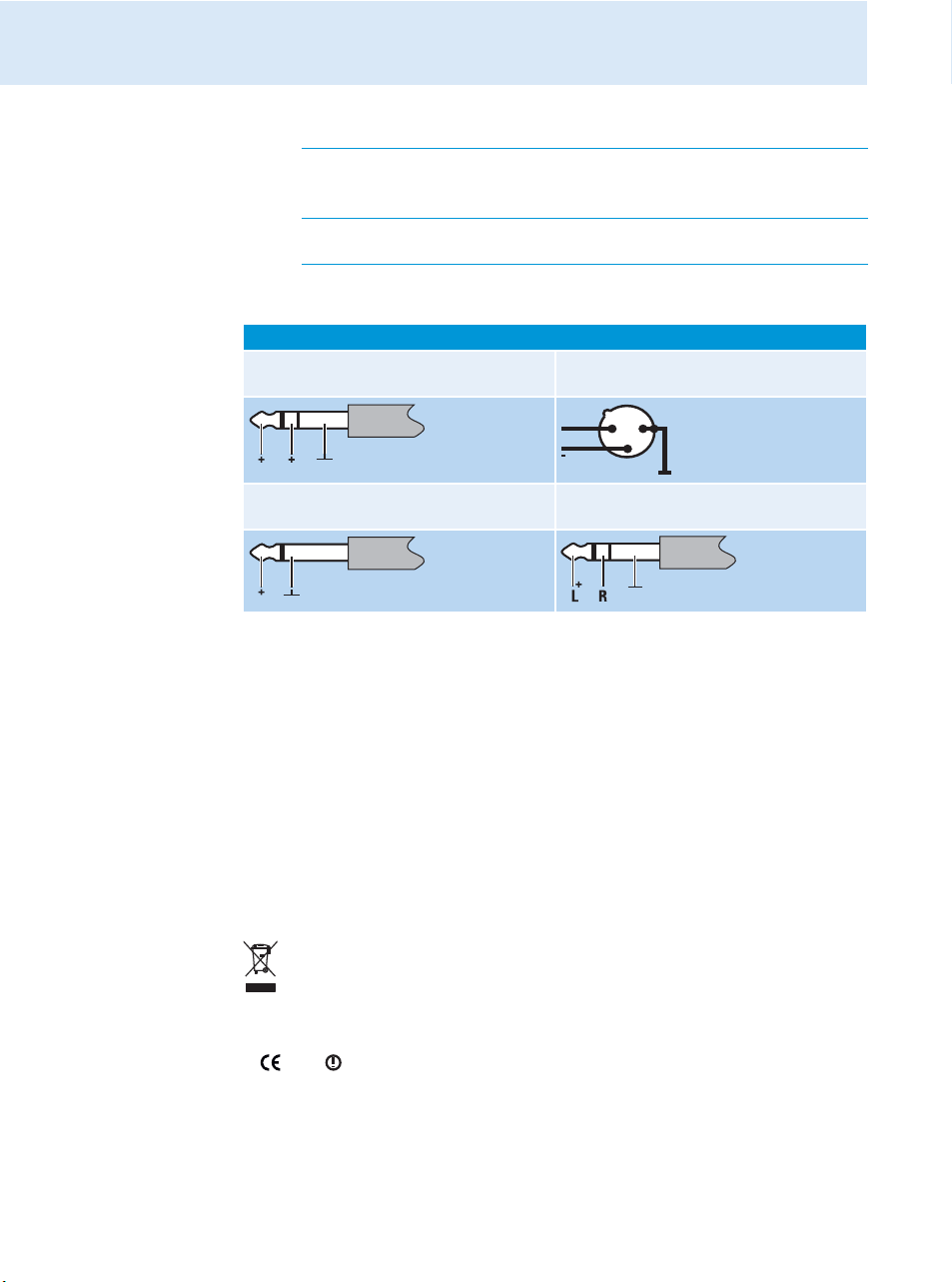
Connector assignment
Audio
¼’’ (6.3 mm) stereo jack plug,
balanced (Audio In/Loop out)
and DMOSR2050
0
XLR-3F connector,
balanced (Audio In)
+
21
3
¼’’ (6.3 mm) mono jack plug,
unbalanced (Audio In/Loop out)
¼’’ (6.3 mm) stereo jack plug
for headphone output
Manufacturer Declarations
Warranty
Sennheiser electronic GmbH & Co. KG gives a warranty of 24 months on this product.
For the current warranty conditions, please visit our web site at www.sennheiser.com or
contact your Sennheiser partner.
In compliance with the following requirements
• RoHS Directive (2002/95/EC)
• WEEE Directive (2002/96/EC)
Please dispose of the transmitter at the end of its operational lifetime by taking it to
your local collection point or recycling center for such equipment.
CE Declaration of Conformity
•
0682
• R&TTE Directive (1999/5/EC), Low Voltage Directive (2006/95/EC)
The declarations are available at www.sennheiser.com.
Before putting the device into operation, please observe the respective country-specific
regulations.
26
Page 28

Manufacturer Declarations
Statements regarding FCC and Industry Canada
This device complies with Part 15 of the FCC Rules and with RSS-210 of Industry Canada.
Operation is subject to the following two conditions: (1) this device may not cause harmful
interference, and (2) this device must accept any interference received, including interference that may cause undesired operation.
This equipment has been tested and found to comply with the limits for a Class B digital
device, pursuant to Part 15 of the FCC Rules. These limits are designed to provide reasonable
protection against harmful interference in a residential installation. This equipment generates, uses and can radiate radio frequency energy and, if not installed and used in accordance
with the instructions, may cause harmful interference to radio communications. However,
there is no guarantee that interference will not occur in a particular installation. If this equipment does cause harmful interference to radio or television reception, which can be determined by turning the equipment off and on, the user is encouraged to try to correct the interference by one or more of the following measures:
• Reorient or relocate the receiving antenna.
• Increase the separation between the equipment and receiver.
• Connect the equipment into an outlet on a circuit different from that to which the receiver
is connected.
• Consult the dealer or an experienced radio/TV technician for help.
This class B digital device complies with the Canadian ICES-003.
Changes or modifications made to this equipment not expressly approved by Sennheiser
electronic Corp. may void the FCC authorization to operate this equipment.
Before putting the device into operation, please observe the respective country-specific
regulations!
27
Page 29

Sennheiser electronic GmbH & Co. KG
Am Labor 1, 30900 Wedemark, Germany
www.sennheiser.com
Printed in Germany
Publ. 01/09
529682/A01
 Loading...