

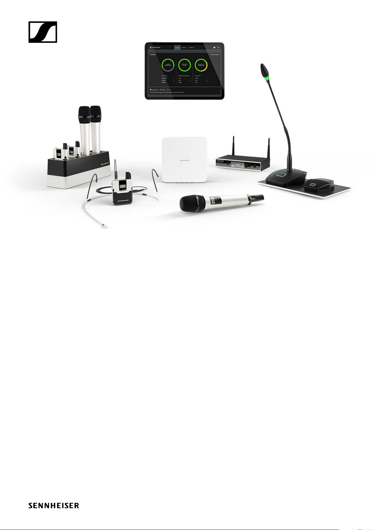
SpeechLine Digital Wireless
Antenna solutions and recommendations
on antenna mounting for the SL Rack Receiver DW
Sennheiser electronic GmbH & Co. KG
Am Labor 1, 30900 Wedemark, Germany, www.sennheiser.com
AN 1106 v2.0

Antenna solutions and recommendations on antenna mounting
SpeechLine Digital Wireless - SL Rack Receiver DW
Contents
Antenna solutions for SpeechLine Digital Wireless.................................3
Antenna setup planning for SpeechLine Digital Wireless......................... 3
Mounting instructions for the AWM 2 and AWM 4 ..............................3
Antenna mounting options ......................................................4
Option 1:
Connecting the AWM 2/AWM 4 directly to the receiver(s)........................4
Option 2:
Combining multiple links to one AWM 2/AWM 4................................ 6
Option 3:
Rack mounting - front.......................................................10
Option 4:
Rack mounting - rear .......................................................10
Further important information on antenna usage .................................11
Reflecting surfaces.........................................................11
Blocking effects from other transmitters ......................................12
AN 1106 v2.0 | 2/12
Antenna solutions and recommendations on antenna mounting
SpeechLine Digital Wireless - SL Rack Receiver DW
Antenna solutions for SpeechLine Digital Wireless
This document gives an overview over several possibilities of mounting and using antennas for a
SpeechLine Digital Wireless system. Furthermore, this document provides recommendations on
several aspects which should be considered for the different antenna solutions.
Antenna setup planning for SpeechLine Digital Wireless
When planning the installation of SpeechLine Digital Wireless rack receivers and antennas for each
room, observe the following guidelines:
f Mount all SpeechLine Digital Wireless receivers of one room together in one rack.
f Make sure to have a direct line of sight between the transmitters and the receiving antennas.
f Depending on the room characteristics there are several options how to install the receiving
antennas. We recommend the following options in this order:
• Option 1: remotely mounted using the AWM 2 for one receiver or AWM 4 for two receivers
• Option 2: remotely mounted using the AWM 2 or AWM 4 with multiple receivers combined
(passive combiner)
• Option 3: mounted in a rack (front)
• Option 4: mounted in a rack (rear)
f When mounting antennas remotely, observe the minimum distance to possibly existing DECT
access points and also take into account the cable lengths.
f Always switch all receivers on and off with a common power supply (e.g. a multi-outlet power
strip with a central on/off switch) in order to achieve the best performance of a system.
For further technical details and recommendations on the four options please refer to the
chapter „Antenna mounting options“ starting on the next page.
Mounting instructions for the AWM 2 and AWM 4
When using the AWM 2 or AWM 4 please observe the respective mounting instructions. You will
find them in the download sections of the respective product pages:
www.sennheiser.com/awm-2
www.sennheiser.com/awm-4
AN 1106 v2.0 | 3/12
Antenna solutions and recommendations on antenna mounting
SpeechLine Digital Wireless - SL Rack Receiver DW
Antenna mounting options
As mentioned above, there are multiple possibilities for remote mounting the anntennas. In the
following, we will explain the most common options with additional recommendations in order of
preference.
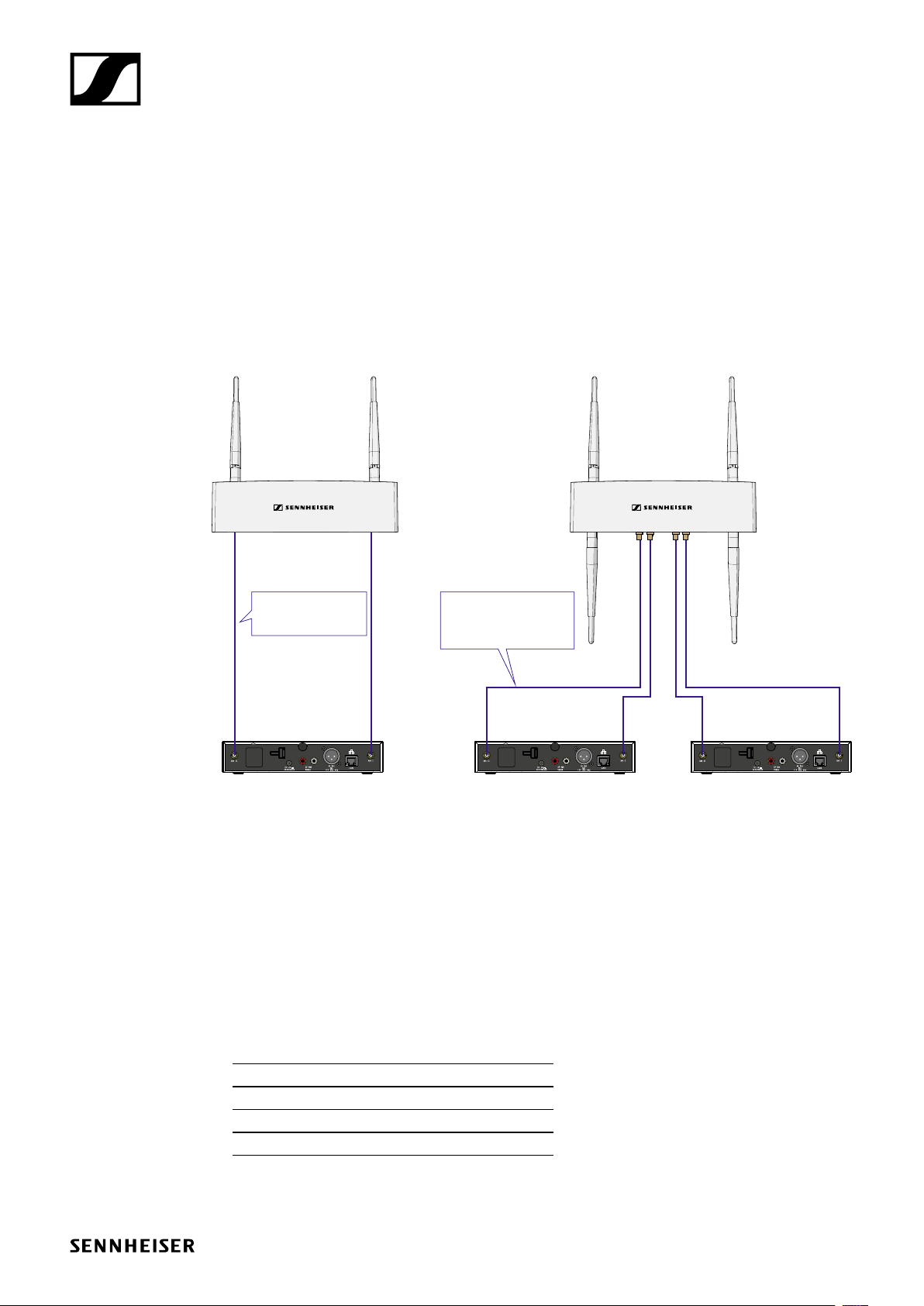
Option 1: Connecting the AWM 2/AWM 4 directly to the receiver(s)
You can connect one receiver directly to one AWM 2 antenna wall mount or you can connect two
receivers directly to one AWM 4 antenna wall mount.
AWM 4AWM 2
CL 5 (5 m / 16.4 ft)
CL 10 (10 m / 32.8 ft)
CL 20 (20 m / 65.6 ft)
CL 1 PP (1 m / 3.3 ft)
CL 5 PP (5 m / 16.4 ft)
CL 10 PP (10 m / 32.8 ft)
CL 20 PP (20 m / 65.6 ft)
Link I - Ant ILink I - Ant II Link II - Ant ILink II - Ant II
SL Rack Receiver DWSL Rack Receiver DW SL Rack Receiver DW
Signal loss due to extension cables
In this scenario, using extension cables for remote antenna mounting results in a loss of transmission power, depending on the cable length. You can compensate this signal loss by configuring the
transmission power of the receiver accordingly.
f Observe the following minimum transmission power settings (SL Rack Receiver DW: System
Settings menu -> RF Power) for the respective cable lengths:
• Cable length of 5 m -> at least level 1
• Cable length of 10 m -> selected level +1, at least level 2
• Cable length of 20 m -> selected level +1, at least level 3
• Cable length of 25 m and longer -> selected level +2, at least level 4
f The Sennheiser CL antenna cables have the following attenuation:
CL 5 2.5 dB CL 1 PP 0.5 dB
CL 10 5 dB CL 5 PP 2.5 dB
CL 20 10 dB CL 10 PP 5 dB
CL 20 PP 10 dB
AN 1106 v2.0 | 4/12

Antenna solutions and recommendations on antenna mounting
SpeechLine Digital Wireless - SL Rack Receiver DW
Remote antenna distances and line of sight
If you are using multiple antenna wall mounts (AWM 2/AWM 4) in one room or if individual installation and mounting of the antennas is desired, please observe the following aspects:
f Position all antennas as close as possible to each other.
f Make sure that the distances between all antennas are all equal and the same as on the back of
the receiver or on the AWM 2 antenna wall mount.
f If possible, group the antennas as follows:
• All A antennas from the receivers’ ANT I sockets in one group according to the aforementioned requirements
• All B antennas from the receivers’ ANT II sockets in one group according to the aforementioned requirements
Ant II Ant I
All antennas B from Ant II sockets
of all SL Rack Receiver DW units
Distance to reflecting surface / obstacle:
min. 7.5 cm (3"), recommended 17 cm (7")
B B B
minimum 7.5 cm (3")
recommended 17 cm (7")
B
B
B
B
A
A
A
A
All antennas A from Ant I sockets
of all SL Rack Receiver DW units
A A A
B B B
≤ 1 m (39")
B
≤ 1 m (39")
B
min. 17 cm (7")
A
A
A A A
f When using multiple AWM 2/AWM 4 antenna wall mounts, make sure that the distances bet-
ween all antennas are equal:
f If possible, position the antennas so that there is a direct line of sight (without obstacles) bet-
ween the transmitters and the antennas.
AN 1106 v2.0 | 5/12

Antenna solutions and recommendations on antenna mounting
SpeechLine Digital Wireless - SL Rack Receiver DW
Option 2: Combining multiple links to one AWM 2/AWM 4
With this variant, you can use passive antenna splitters (SL PASC 2 or SL PASC 4) together with the
AWM 2 or AWM 4 to combine the antenna signals from multiple receivers. This reduces the number
of antenna cables required to a minimum.
Combining up to 2 links using the AWM 2 and SL PASC 2
The following illustration shows an example of how to combine up to 2 links with one AWM 2 antenna wall mount. This reduces the number of antenna cables required from 4 to 2.
Use the following Sennheiser cables
for connecting the AWM 2 to the SL
PASC 2:
CL 5 (5 m / 16.4 ft)
art. no. 505976
CL 10 (10 m / 32.8 ft)
art. no. 506263
SL RACK RECEIVER DW ANTENNA I
1 2
1 2 3 4
ANT I
SL RACK RECEIVER DW ANTENNA II
SL RACK RECEIVER DW ANTENNA II
1
1 2 4
2
ANT II
Cables for connecting the SL PASC 2 to the
SL Rack Receiver DW are supplied with the
SL PASC 2.
f Please observe the information below on the length of the extension cables:
„Signal loss due to extension cables and antenna splitters“
AN 1106 v2.0 | 6/12

Antenna solutions and recommendations on antenna mounting
SpeechLine Digital Wireless - SL Rack Receiver DW
Combining up to 4 links using the AWM 2 and the SL PASC 4
The following illustration shows an example of how to combine up to 4 links with one AWM 2 antenna wall mount. This reduces the number of antenna cables required from 8 to 2.
AWM 2
Use the following Sennheiser cables
for connecting the AWM 2 to the SL
PASC 4:
CL 5 (5 m / 16.4 ft)
art. no. 505976
CL 10 (10 m / 32.8 ft)
art. no. 506263
SL PASC 4
SL RACK RECEIVER DW ANTENNA I
1 2 3 4
ANT I
SL RACK RECEIVER DW ANTENNA II
1 2 3 4
ANT II
Cables for connecting the SL PASC 4 to
the SL Rack Receiver DW are supplied
with the SL PASC 4.
SL Rack Receiver DW
f Please observe the information below on the length of the extension cables:
„Signal loss due to extension cables and antenna splitters“
Always combine all antenna sockets ANT I of all receivers and all antenna sockets ANT II
of all receivers respectively to one of the two antennas of the AWM 2. If you are using only
3 of the 4 connections on the antenna splitter, you should close the unused connection
with a terminating resistor (50 Ω) to minimize interfering signals and maximize transmission power.
AN 1106 v2.0 | 7/12

Antenna solutions and recommendations on antenna mounting
SpeechLine Digital Wireless - SL Rack Receiver DW
Combining up to 8 links using the AWM 4 and the SL PASC 4
The following illustration shows an example of how to combine up to 8 links with one AWM 4 antenna wall mount. This reduces the number of antenna cables required from 16 to 4.
Use the following Sennheiser cables for
connecting the AWM 4 to the SL PASC 4:
SL RACK RECEIVER DW ANTENNA I
1 2 3 4
ANT I
SL PASC 4
SL RACK RECEIVER DW ANTENNA II
1 2 3 4
AWM 4
CL 1 PP (1 m / 3.3 ft)
art. no. 507425
CL 5 PP (5 m / 16.4 ft)
art. no. 507426
CL 10 PP (10 m / 32.8 ft)
art. no. 507427
Link IILink I
SL PASC 4
SL RACK RECEIVER DW ANTENNA I
1 2 3 4
ANT II
ANT I
SL RACK RECEIVER DW ANTENNA II
1 2 3 4
ANT II
SL Rack Receiver DW
SL Rack Receiver DW
Cables for connecting the SL PASC 4 to the SL Rack Receiver DW are supplied with the SL PASC 4.
f Please observe the information below on the length of the extension cables:
„Signal loss due to extension cables and antenna splitters“
Always combine all antenna sockets ANT I of up to four receivers and all antenna sockets
ANT II of up to four receivers respectively to the two sockets of one link of the AWM 4.
If you are not using all connections on the antenna splitter, you should close the unused
connections with a terminating resistor (50 Ω) to minimize interfering signals and maximize transmission power.
AN 1106 v2.0 | 8/12

Antenna solutions and recommendations on antenna mounting
SpeechLine Digital Wireless - SL Rack Receiver DW
Signal loss due to extension cables and antenna splitters
In this scenario, the use of extension cables and antenna splitters with a remotely mounted antenna
may result in loss of transmission power, depending on the cable length.
You can compensate this signal loss by configuring the transmission power of the receiver accordingly. Observe the following minimum transmission power settings (SL Rack Receiver DW: System
Settings menu -> RF Power) for the respective cable lengths. The antenna splitter causes about as
much signal loss as a cable length of 15 m. These losses must be included in the calculation of the
transmission power level.
We recommend the following cable lengths in combination with the antenna splitter:
• Receiver to splitter: 1 m -> splitter to AWM 2/4: 1 m
• Receiver to splitter: 1 m -> splitter to AWM 2/4: 5 m
• Receiver to splitter: 1 m -> splitter to AWM 2/4: 10 m
• Receiver to splitter: 5 m -> splitter to AWM 2/4: 1 m
• Receiver to splitter: 5 m -> splitter to AWM 2/4: 5 m
• Receiver to splitter: 10 m -> splitter to AWM 2/4: 1 m
Cables longer than 10 m are not recommended for this variant.
This results in the following transmission power levels to be set in the menu of the receiver or
simultaneously for all receivers in the Sennheiser Control Cockpit software:
• 5 m cable length plus splitter -> at least level 2
• 10 m cable length plus splitter -> at least level 3
The Sennheiser CL antenna cables have the following attenuation:
CL 5 2.5 dB CL 1 PP 0.5 dB
CL 10 5 dB CL 5 PP 2.5 dB
CL 20 10 dB CL 10 PP 5 dB
CL 20 PP 10 dB
Direct line of sight
f If possible, position the antennas so that there is a direct line of sight (without obstacles) bet-
ween the transmitters and the antennas.
AN 1106 v2.0 | 9/12

Antenna solutions and recommendations on antenna mounting
SpeechLine Digital Wireless - SL Rack Receiver DW
Option 3: Rack mounting - front
If you wish to install the antennas together with the receivers in a rack, we recommend mounting
the antennas on the front side of the rack using the GA 4 mounting kit.
f Always leave 1 U of space between receivers
and antennas.
f Position the antennas at an angle of about
45°.
Option 4: Rack mounting - rear
If you cannot mount the antennas at the front of the rack (option 3), you can also mount them at the
rear of the receiver in the rack. When mounting, observe the following information.
f Position the antennas so that they point at a
180-degree angle away from the receiver.
f Run all cables close to the receivers to
prevent the cables from interfering with the
antenna reception. Use the cable grip.
f For best system performance, make sure
that the antennas are not covered or shielded by blocking obstacles such as cables,
metal plates, or cases.
f In this case, and if possible, make sure that
there is a direct line of sight between the
transmitters and the receivers for best possible RF performance.
AN 1106 v2.0 | 10/12

Antenna solutions and recommendations on antenna mounting
SpeechLine Digital Wireless - SL Rack Receiver DW
Further important information on antenna usage
Reflecting surfaces
Electrically conducting surfaces (e.g. ceilings with metal constructions) can reflect the RF signal.
The signal is reflected by the electrically conducting surface. At worst, the blue signal and the red
reflected signal are out of phase when they reach the receiver so that the two signals cancel each
other out.
f If you have electrically conducting surfaces in a room, make sure to position the receiver or the
antenna wall mounts so that such reflection effects are avoided.
f If you have a reflecting ceiling, this can be achieved by positioning the antennas closer to the
ceiling.
AN 1106 v2.0 | 11/12

Antenna solutions and recommendations on antenna mounting
SpeechLine Digital Wireless - SL Rack Receiver DW
Blocking effects from other transmitters
As with all wireless microphone systems, suboptimal positioning of transmitters can lead to blocking effects. To avoid this, please follow these recommendations:
f Position DECT telephone or DECT access points at least 7 m from the antennae.
f Position other wireless devices such as mobile phones at least 1 to 2 m from the antennae.
f When transmitters are currently in use, you must not position any other transmitters in the
blocking area. If you must position them there, switch them off.
Rule of thumb for distance from the blocking area:
Blocking range Free range
ratio 1:1
Example:
AN 1106 v2.0 | 12/12
 Loading...