

Page 1
Page 2

Contents
1. Description ......................
1.1 Model SK 1008 Mikroport
Transmitter. . . . . . . . . . . .. . . . ..
1.2 Microphones ,...
1.3 Model EM 1008 Mikroport
Receiver. . . . .. . . . . . . . . . . . .. . . .
1.4 Antennae . . . . . . ..
2. Preparing equipment for operation. .
2.1 Transmitter..................
2.2 Microphones ,...
2.3 Receiver....................
2.4 Antennae ,.
3. Operation........................
3.1 Transmitter..................
3.2 Microphones ,,""""""""
3.3 Receiver......................
4. Special situations................
4.1 Diversity reception ............
4.2 License ,...........
4.3 Special frequencies .. . . . ... . .
4.4 Tape recording .. . . . . . . . .. . . .
4.5 Powering external units
4.6 2-mV output..................
4.7 Hum prevention ,...
,
Page
1
1
2
3
4
5
5
5
6
6
6
6
7
7
7
7
7
7
J
:)
Page 3
0
a
1. Description
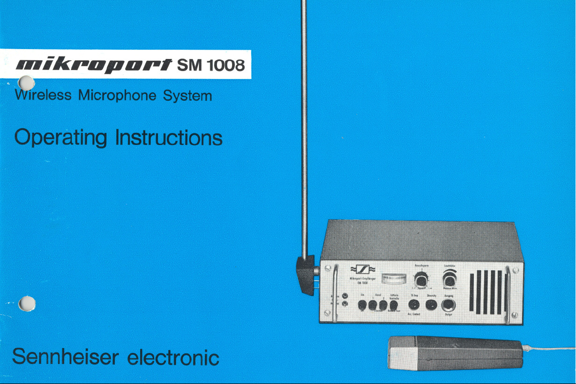
The SM 1008 wireless microphone
system consists of a battery-operated
miniature transmitter, Model SK 1008,
which can be equipped with several
different special microphones, and the
battery/AC operated receiver, Model
EM 1008, which can be operated with
a variety of special antennae.
1.1 Model SK 1008 Mikroport
transmitter
The Mikroport transmitter is operated
trom an ordinary 9 V battery, Standard
units are designed for two trequencies:
36.7 and 37.1 MHz. Two plug-in micro-
phones and seven special microphones,
which can be connected via short leads,
permit adaptation to even unusual appli-
cations. A plug-in antenna is supplied
with the transmitter.
1.2 Microphones
Two different plug-in microphones may
be combined with the Mikroport trans-
mitter into a single unit. The combi-
nation, which is no larger than a con-
ventional microphone, may be either
held in the hand or used as a lavalier
microphone via its built-in cord.
Model MD 1008 plug-in microphone,
which has spherical characteristics, is
preferable whenever it is essential to
obtain minimum sensitivity to vibration,
and where (especially during interviews)
several persons speak into the micro-
phone trom different directions. However,
where there is a high ambient noise
level, reverberation, or the possibility of
acoustic feedback, it is recommended
that the Model MD 4008 plug-in micro-
phone, which has super-cardioid di-
rectional characteristics be employed.
Where concealment of the transmitter
is desired, special microphones may
still be used, connected to the micro-
phone socket of the SK 1008 transmitter
via a short cable. The most frequently
used unit, for this application, is the
Model MD 214/1 Lavalier suspension
microphone. Besides double internal
suspension, which renders this micro-
phone strongly resistant to noises pro-
duced by friction, the Model MD 214/1
dynamic lavalier microphone has a
shaped frequency response that com-
pensates for attenuation of high fre-
quencies caused by the chin of the
speaker. The Model 405-T directional
hand-held microphone can be used in
a similar fashion, worn in an outside
pocket, permitting the transmitter to be
switched on and off by means of the
switch on the microphone. The Model
MM 61-2 fountain pen microphone and
Model MM 24-2 lapel microphone are
even more inconspicuous, although
their transmission quality is not as
good as that of the previously-mentioned
microphones. Where stringent quality
requirements exist, the Mikroport trans-
mitter mayaiso be connected to one
of our transistorized capacitor micro-
phones via a special cable, Model
KAM-1. Either the Model MKH 104 with
spherical characteristics, the Model
MKH 404 with cardioid characteristics,
or the Model MKH 804 with ultra-direc-
tional characteristics, may be employed.
Power for these microphones is obtained
from the Mikroport transmitter battery.
1.3 Model EM 1008 Mikroport
receiver
This newly-developed receiver may be
operated from the AC line or from a
standard 9 V battery. The two antenna
inputs (60-ohm and 240-ohm impedance)
permit the use of different antennae.
Transmitter field strength can be con-
tinuously monitored with its built-in
meter. A balanced, ungrounded 1.55 V
audio output provides a signal at less
than 2 % distortion. The signal may
also be monitored simultaneously at
variable volume via a built-in loud-
speaker.
1.4 Antennae
The wire antenna supplied with the
Mikroport receiver does not have the
same reception performance as the
Model TA 203 telescopic accessory
antenna. If a Ionger antenna cable is
required, e. g., for diversity reception,
(See Section 4.1), it is recommended
that a tuned 240-ohm dipole be prepa-
red with a cable of suitable length.
2. Preparing the equipment for
operation
Reliable operation of the entire system
can only be guaranteed by the manu-
facturer if all parts used are original
Sennheiser products and no unautho-
rized alterations have been made by a
third party.
Page 4
If the micraphone spacing is increased,
(or if loudness is reduced), It will be
necessary to advance the control ac-
cordingly, while loud speech or a
reduction in micraphone distance re-
quires a lower setting. To facilitate
precise matching of the system in studio
operation, it should be mentioned that
correct adjustment of the sensitivity
control is obtained when the audio
output of the receiver supplies + 6 db
(1.55 volts) at modulation peaks.
3.2 Microphones
In operating the micraphones it is
merely necessary to note that directional
types (MD 4008, MD 405-T, MKH 404
and MKH 804) should be pointed
directly at the sound source wherever
possible, since they are naturally less
sensitive to sounds coming from the
sides and rear.
3.3 Receiver Model EM 1008
The receiver is switched on by depress-
ing the "ON" push button. In battery
operation it is also advisable to depress
the "battery test" push button to deter-
mine whether the pointer deflects weil
into the red range of the indicating
instrument, indicating an adequate re-
serve. The same channel selected on
the transmitter must be selected by
depressing the appropriate button on
the receiver. As soon as the transmitter
is switched on, the instrument will show
the fjeld strength. The pointer must
come to rest in the green section,
indicating an adequate signal is present.
Advancing the volume control enables
the transmitted signal to be monitored
by means of the built-in loudspeaker.
This output signal is available for
feeding amplifier or tape recorder sys-
tems having a standard studio input
level of 1.5 V (+ 6 db). To prevent
noise being transmitted to the amplifiers
or tape recorder systems when the
transmitter is off, the 'squelch' control
should be adjusted by turning it slowly
clockwise, starting fram position 1, until
the meter needle jumps into the blue
field. When the transmitter is switched
on, the squelch relay will be activated
and the meter will show fjeld strength.
When the automatic squelch feature is
not required, the squelch contra I can
be lett at position 1. In order to reliably
check operation it is advisable to switch
on the transmitter and walk over the
entire transmission area while a second
person observes the field strength indi-
cation. Excessively low antenna voltage,
indicated by a pointer on the lett-hand
side of the scale may be impraved by
reorienting the antenna.
4. Special situations
4.1 Diversity reception
For particularly important applications,
where not even the slightest temporary
reduction of transmission quality can
be tolerated, it is possible for two or
i
E
C'-
M
,...
I
~
~~
'-'
'-
Dipole antenna
construction
beliebig
as desired
Fig. 11
j
J)
6
Page 5

()
0
7
more receivers to be operated in the
diversity mode.
Since it is highly unlikely that field
strength minima will occur simultane-
ously at two different antenna sites,
the antennae of the two receivers
should be located at a distance of
several yards from each other. The two
receivers must be connected to each
other, the cables provided for diversity
operation being inserted into the 'diver-
sity' sockets. The equipment connected
to the 'output' socket of only one recei-
ver will then automatically be fed by
this receiver, or by both receivers in
common, when both receive a suffi-
ciently high antenna voltage.
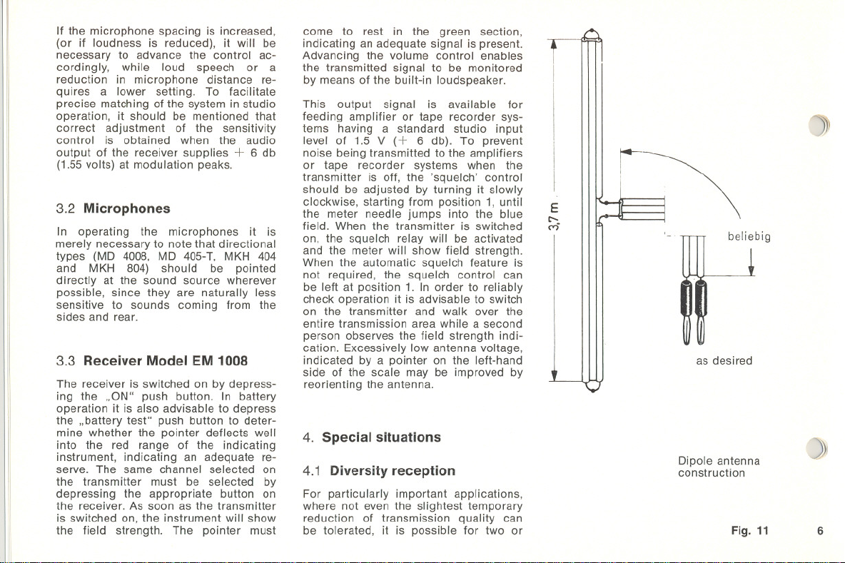
For this application, it is recommended
that a folded dipole be prepared from
240-ohm TV antenna cable. This is done
as indicated in Fig. 11. A 12 foot long
antenna cable is shorted at both ends.
Then, one of the two conductors is cut
in the center and connected with the
conductors of a lead-in cable of any
desired length. The folded dipole thus
obtained must be connected to the
antenna socket on the front of the
receiver marked '240 ohm'. The actual
dipole section (12 feet long) should
then be vertically oriented.
4.2 License
The purchaser of this equipment is
responsible for obtaining the license to
operate it from the appropriate autho-
rities.
4.3 Special frequencies
While the standard carrier frequencies
are set to 36.7 and 37.1 MHz, the
system can also be supplied with any
two frequencies between 25 and 45 MHz,
(with a frequency spacing of 0.3 to
0.5 MHz), as an optional extra.
4.4 Tape recording
A changeover contact operated by the
squelchcircuit of the receiver is acces-
sible at the 'auxiliary contact' socket.
This changeover contact enables the
transports of tape recorders to be
operated by electrical remote control
- both by means of the NC and NO
contacts - so that they start when the
transmitter is switched on and stop
with it is switched off. The circuitry of
this contact arrangement can be seen
from the diagram located on the rear
panel of the receiver.
4.5 Powering external units
A OC voltage of 4 V, at a maximum
current of 30 mA, is available at con-
tact 4 of the terminal mentioned in
Section 4.4, for powering external units.
4.6 2 mV output
If the amplifier or tape recorder used
with the receiver does not have a 1.55 V
input, an additional balanced, ungroun-
ded output voltage of 2 mV, with a
source impedance of 10 ohm, is avai-
lable at the contacts 2 and 4 of the
'output' socket. This output can be
connected to the low impedance, baian-
ced microphone input of an amplifier.
4.7 Hum
Since the receiver is already connected
to ground via the ground contact of
the AC power plug, it is essential to
prevent ground loops when subsequent
amplifiers or tape recorders are con-
nected. Regardless of whether the
subsequent amplifier has a balanced
or an unbalanced input, the shielding
of the amplifier cable must be conti-
nued to the contact on the amplifier
housing. On the receiver side, the
screening shielding should remain un-
connected and must, therefore, be kept
from touching contact 2 of the standard
plug.
If, on the other hand, the grounded
plug is replaced by a standard plug
which does not automatically ground
the equipment, it will be necessary for
the receiver housing to be directly
grounded via aseparate line, or con-
nected via the cable shielding, to the
amplifier ground connection. In this
case, the shielding of the cable must
be connected to contact 2 of the stan-
dard plug on the receiver side.
Page 6

Technical
Carrierfrequencies,switchable. . .
36.7 and 37.1 MHz
Data
SK 1008
Frequency drift at temperatures
between + 68° F (+ 20° C) and
+ 113° F (+ 45° C) and an ope-
rating voltage deviation of 200/0
Radiated output. . . . . . . . .
Type of modulation. . . .
Noiseswing. . . . . . . . . . .
AF input sensitivity(variable) . . .
Transmissionrange:!: 3 db . . . .
Pre-emphasis. . . . . . .
Distortion factor at 40 kHz swing. .
Current consumption . . . . . . .
Battery
. . . . . . . . . . . . .
Batterylife. . . . . . . .
< 15kHz
~)
approximately 1 mW
FM
~ 100cis
1 mV/40 kHz swing
35 Hz - 20 kHz
50 ,usec
~20f0
10 mA
optional: 1 dry battery Eveready No. 216, Dai-
mon No. 333, Pertrix No. 438 or rechargeable
nickel-cadmium battery Deac Tr 7/8 or equi-
valent
()~))
7 hours
Dimensions
Weight. . .
. . . . . . .
. . . . . . .
5.9" x 1.7"x 1.3" (without microphone)
0.89 Ib. (with battery; without microphone)
8
Page 7

Technical
Data
MD
1008
Response.. . . . . . . . . . .
Maximum deviation from specified
frequency response (for lavalier
microphone) .........
Field no-load transmission factor at
1000Hz. . . . . . . . . . . .
Electricalimpedance. . . . . . .
(I
Directional characteristic . . . . .
Dimensions . . . . . . . . . . .
Weight.. . . . . . . . . . . . .
60 Hz - 14 kHz
:!: 3 dB
0.2 mV/l-tbar
400 ohms
spherical
1.6" x 1.7" x 1.3"
0.24Ib.
~
9
Technical
Data
EM 1008
InputI. . . . . .
Input 11
. . . . . . . . . . . . .
Output. . . . . . . . . . . . . .
Output voltage with 40 kHz swing
and more than 5 flV antenna
voltage. . . . . . . . . . . .
Audiofrequencyrange. . . . . .
Deviation from specified frequency
response (De-emphasis 50 flsec)
Non-linear distortions at 40 kHz
swing and 200 I-tVantenna voltage
Spurious voltage ratio at 40 kHz
swing and 2.5 I-tVantenna voltage
Spurious voltage ratio at 40 kHz
swing and more than 20 I-tV
antennavoltage. . . .
unbalanced, for 60-ohm source impedance,
13 mm RF jack complying with DIN 47 283
balanced, for 240-ohm sourees: plug diameter
4 mm; plug spacing 12 mm.
ungrounded; internal resistance 30 ohm; no-
minal loading 300 ohm; 5-pole standard jack
complying with DIN 41 524
1.55V:!:2dB
50 Hz - 15 kHz
:!: 2 dB max.
< 2 %
> 26 dB
> 50 dB
Page 8

EM 1008
I
I
Signal-to-noise ratio at 40 kHz swing
and more than 50 pV antenna
voltage. . . . . . . . . . .
Reception frequencies
Pull-in range of automatie tuning
Adjacent channel rejection with
0.4 MHz channel spacing
Electronic squelch circuit; Adjus-
table cut-off antenna voltage. .
Diversityoperation. . . . . . . .
Tape recorder remote control . . .
Power supply
Power consumption with AC line
. . . . . . . . . .
operation. . . . . . . . . .
Une fuse . . . . . . . . . . . .
Transistor complement . . . . . .
Diodes
Dimensions
Weight
. . . . . . . . . . . . .
. . . . . . . . . . .
. . . . . .
. . . . .
> 65 db
36.7 and 37.1 MHz in accordance with the
transmitter
:t 100 kHz
> 60 db
2 p,V - 1 mV (Indication by field strenght
meter)
2 or more receivers can be connected to each
other at the ,diversity' jacks via a 5-pole jack
complying with DIN41 524
Auxiliary contact jack to be connected with
remote control terminal of the tape recorder;
5-pole standard jack complying with DIN41 524
Optionally from the built-in AC power pack
110/220 V, 50-60 Hz or from 9 V battery, for
example: Eveready No. 276, Daimon No. 339,
Pertrix No. 439, Sonnenschein Dryfit accumu-
lator 4 L x 2, 8 V
approximately 2 W
0.035 A
1 x AF 102, 6 x AF 124,
6xAC161,
1 x matched pair AC 117,
AC 175,
1 x AC 153, 2 x AC 127
1 x OA126/6,1 x BA111
2 x OA91, 2 x AA119,
1 x BA100, 1 x ZF 9.1
11.7x 6.6 x 3.7"
approximately 8.1 Ib.
~)
»»)
10
Page 9

(Oi
Technical
Data
T203
Input (unbalanced) . . . . . . . .
Output (unbalanced)
Output voltage with 40 kHz swing
and more than 5 f-lVantenna vol-
tage. . . . . . . . . . . . .
Audio-trequency range. . . . . .
. . . . . . .
tor 50-ohm sources
internal resistance 1 K;
nominal loading 2 K
1 V, variable
100 - 15000 Hz
cl
11
Deviation trom specitied trequency
response (De-emphasis 50 usec)
Non-linear distortion at 40 kHzswing
and 200 f-lVantenna voltage tor
1 V output voltage. . . . . .
Signal-to-noise ratio at 40 kHz swing
and more than 20 f-lVantenna
voltage. . . . . . . .
Reception trequencies
26 db signal-to-noise ratio with swing
ot 25 kHz ..,.......
Adjacent channel rejection (400 kHz
spacing) . . . . . . . . . . .
Power supply
Operating period
Dimensions
Weight (with battery) . . . . . . .
. . . .. ...
. . . . . . .
. . . . . .
. . . . . .
;;;; :!: 2 dB
;;;;3%
> 50dB
36.7 MHz and 37.1 MHz
tram 2 flV
approximately 50 db
9 V battery, tor example Eveready No. 226,
Pertrix No. 29 or 7.5 V DEAC accumulator,
capacity 150 mAh
Battery, approximately 20 hours;
accumulator approximately 10 hours
1.3" x 3.4" x 4.7"
approximately 0.6 Ib.
Page 10

Technical
Data
Frequency response. . . . . . .
Maximum deviation from nominal
curve ,.
80 to 12,000 Hz
:t 3 db
11
111
11
1
111
1
11111
:
1
11I1
I
I
111:1
111111
iIIill
11111I
11111.1
111\i\
11I111
III!I:
MD 4008
1I
11
11
11:
111
Field no-load transmission factor at
1000 Hz ,.....
Electrical impedance . . . . . . .
Directionalcharacteristic . . . . .
Dimensions
Weight
. . . . . . . . . . . . .
. . . . . . .
.2 mV/,ubar
700 ohms
super cardioid
1.6" x 1.7" x 1.3"
.24Ibs.
0)
.»)
12
Page 11

 Loading...