

Sennheiser SKP 500 User Manual

SKP 500
EK 500
Instructions for use
/

Thank you for choosing Sennheiser!
We have designed this product to give you reliable
operation over many years. Over half a century of
accumulated expertise in the design and manufacture of
high-quality electro-acoustic equipment have made
Sennheiser a world-leading company in this field.
Please take a few moments to read these instructions
carefully, as we want you to enjoy your new Sennheiser
product quickly and to the fullest.
2

Contents
The SKP 500 G2 plug-on transmitter .................................... 4
The channel bank system .................................................. 4
Safety instructions .................................................................... 5
Delivery includes ....................................................................... 5
Areas of application .................................................................. 6
The operating controls ............................................................. 7
Indications and displays .......................................................... 8
Preparing the plug-on transmitter for use ....................... 10
Inserting and replacing the batteries .......................... 10
Plugging the plug-on transmitter onto a
microphone ........................................................................ 11
Using the plug-on transmitter ............................................. 12
Switching the plug-on transmitter on/off .................. 12
Muting the plug-on transmitter ................................... 12
Activating/deactivating the lock mode ....................... 13
The operating menu .............................................................. 14
The buttons ....................................................................... 14
Overview of menus .......................................................... 14
Working with the operating menu ............................... 15
Operating menu of the plug-on transmitter .............. 17
Adjustment tips for the operating menu .......................... 19
Switching between channel banks ............................... 19
Switching between the channels in a channel bank . 19
Selecting the frequencies to be stored
in the channel bank “U” .................................................. 19
Adjusting the sensitivity ................................................ 20
Switching the phantom powering on/off ................... 21
Selecting the standard display ...................................... 21
Entering a name ............................................................... 21
Loading the factory-preset default settings .............. 22
Activating/deactivating the pilot tone transmission 22
Activating/deactivating the lock mode ....................... 23
Exiting the operating menu ........................................... 23
Troubleshooting ..................................................................... 24
Error checklist ......................................................... 24
Recommendations and tips ........................................... 25
Care and maintenance ........................................................... 25
Specifications .......................................................................... 26
Accessories .............................................................................. 27
Manufacturer declarations ................................................... 28
Warranty regulations ...................................................... 28
CE Declaration of Conformity ......................................... 28
Batteries or rechargeable batteries .............................. 28
WEEE Declaration ............................................................. 28
3

The SKP 500 G2 plug-on transmitter
The SKP 500 G2 plug-on transmitter is part of the evolution
wireless series ew 500 G2. With this series, Sennheiser
offers high-quality state-of-the-art RF transmission systems
with a high level of operational reliability and ease of use.
Transmitters and receivers permit wireless transmission with
studio-quality sound. The excellent transmission reliability
of the ew 500 G2 series is based on the use of
y further optimized PLL synthesizer and microprocessor
technology,
y the HDX noise reduction system,
y and the pilot tone squelch control.
The channel bank system
The plug-on transmitter is available in five UHF frequency
ranges with 1440 transmission frequencies per frequency
range. Please note: Frequency usage is different for each
country. Your Sennheiser agent will have all the necessary
details on the available legal frequencies for your area.
Range A: 518 to 554 MHz
Range B: 626 to 662 MHz
Range C: 740 to 776 MHz
Range D: 786 to 822 MHz
Range E: 830 to 866 MHz
The plug-on transmitter has nine channel banks with up to
20 switchable channels each.
channel bank 1...8
channel bank U
channel 1
channel 2
channel 20
channel 1
channel 2
channel 20
preset frequency
preset frequency
preset frequency
freely selectable frequency
freely selectable frequency
freely selectable frequency
Each of the channels in the channel banks “1” to “8” has
been factory-preset to a transmission frequency (see
enclosed frequency table). These transmission frequencies
cannot be changed but have been preset so that e.g.
country-specific regulations on frequency usage are taken
into account.
The channel bank “U” (user bank) allows you to store your
selection out of 1440 transmission frequencies that are
freely selectable within the preset frequency range.
4

Safety instructions
Never open an electronic unit! If units are opened by
customers in breach of this instruction, the warranty
becomes null and void.
Use the unit in dry rooms only.
Use a damp cloth for cleaning the unit. Do not use any
cleansing agents or solvents.
Delivery includes
The packaging contains the following items:
y 1 SKP 500 G2 plug-on transmitter
y 2 batteries
y Instructions for use
y 1 POP 1 Plug-on pouch
Suitable microphones (to be ordered separately) for the
plug-on transmitter:
y Dynamic microphones
y Condenser microphones with internal power supply
y Condenser microphones with 48 V phantom powering
5

Areas of application
The plug-on transmitter can be combined with receivers of
the ew 500 G2 series (EM 500 G2 rack-mount receiver or
EK 500 G2 bodypack receiver). The receivers are available in
the same five UHF frequency ranges and are equipped with
the same channel bank system with factory-preset
frequencies. An advantage of the factory-preset
frequencies is that
y a transmission system is ready for immediate use after
switch-on,
y several transmission systems can be operated
simultaneously on the preset frequencies without
causing intermodulation interference.
Together with a matching receiver and a microphone, the
plug-on transmitter is suitable for the following areas of
application:
Transmitter Receiver (to be
ordered separately)
EM 500 G2 y Presentation
SKP 500 G2
EK 500 G2 y Presentation
Area of
application
y Speech
y Vocals
y Speech
y Vocals
y Camera-
mounted
applications
6

The operating controls
Microphone input, XLR-3F socket
(unbalanced)
Mechanical locking ring of XLR-3 socket
LC display
SET button
button (DOWN)
button (UP)
Red LED for operation and
battery status indication (ON/LOW BAT)
ON/OFF button
(serves as the ESC (cancel) key in the
operating menu)
Battery compartment cover
MUTE switch
7
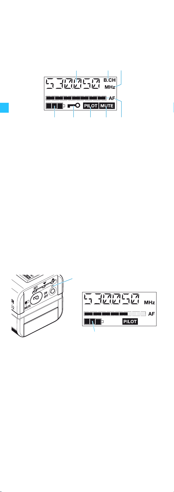
Indications and displays
LC display panel
Alphanumeric display
“B.CH“ – appears when the channel bank and
the channel number are displayed
“MHz“ – appears when the frequency is displayed
4-step battery status display
Lock mode icon
(lock mode is activated)
“PILOT” display
(pilot tone transmission is activated)
“MUTE” display
(audio input is muted)
7-step level display for audio signal “AF”
Operation and battery status indication
The red LED (LOW BAT/ON) provides information on the
current operating state of the plug-on transmitter:
Red LED lit up: The plug-on transmitter is switched
on and the capacity of the batteries/
BA 2015 accupack is sufficient.
Red LED flashing: The batteries are/the BA 2015
accupack is going flat (LOW BAT)!
In addition, the 4-step battery status display on the
display panel provides information on the remaining
battery/BA 2015 accupack capacity:
3 segments: capacity approx. 100 %
2 segments: capacity approx. 70 %
1 segment: capacity approx. 30 %
Battery icon flashing: LOW BAT
8

“MUTE” display
The “MUTE” display appears on the display panel when
the plug-on transmitter is muted (see “Muting the plug-on
transmitter” on page 12).
Modulation display
The level display for audio signal “AF” shows the
modulation of the plug-on transmitter.
When the audio input level is excessively high, the level
display for audio signal “AF” shows full deflection for the
duration of the overmodulation.
“PILOT” display
The “PILOT” display appears on the display panel when
the pilot tone transmission is activated (see “Activating/
deactivating the pilot tone transmission” on page 22).
Display backlighting
After pressing a button, the display remains backlit for
approx. 15 seconds.
9
 Loading...