

Sennheiser SI 1015,SI 1015 Product Sheet
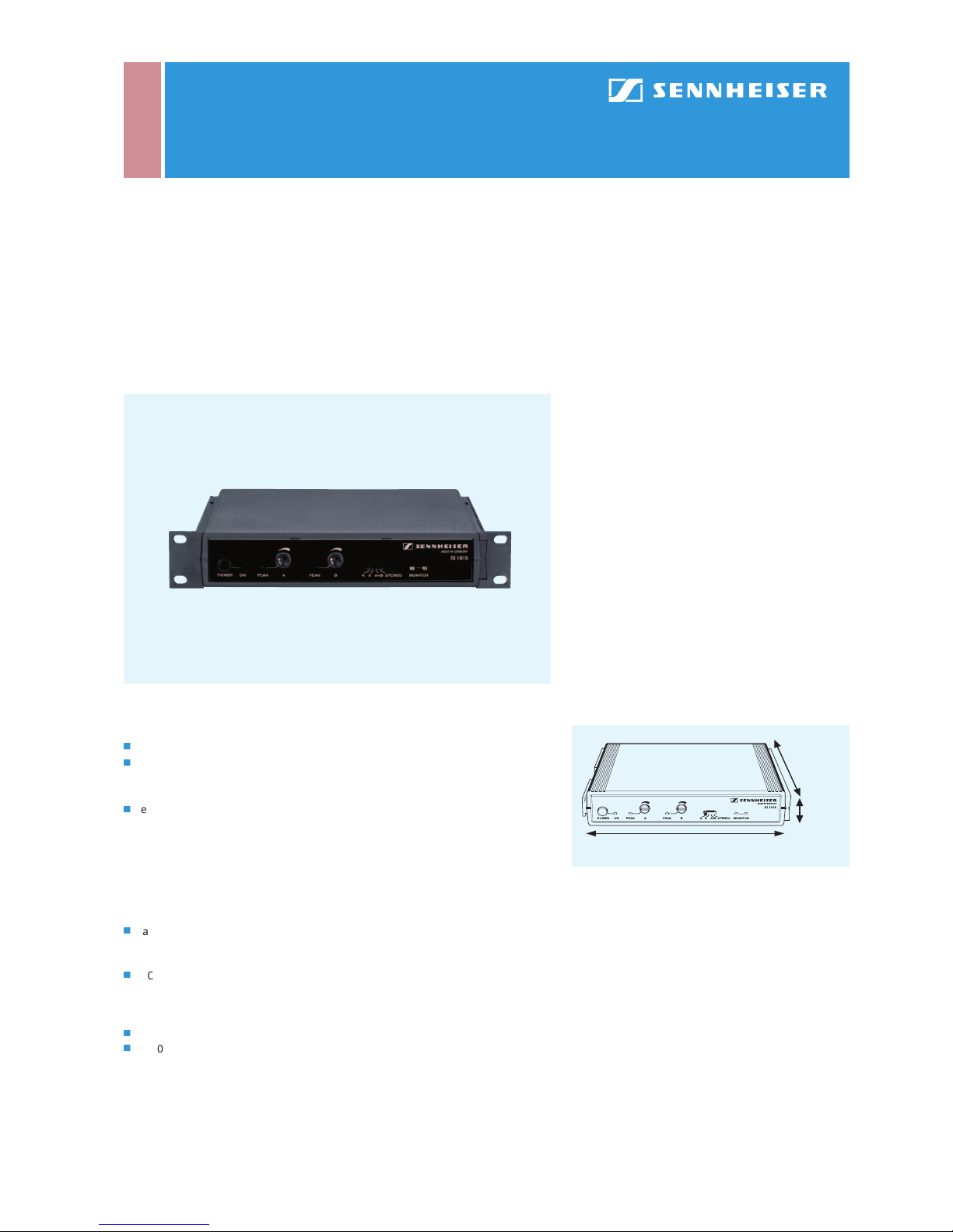
SI 1015
Features
j
Modulator for the carrier frequencies 2.3 and 2.8 MHz
j
Single-channel, two- channel or stereo operation, features
monitoring diodes and a separate barrier strip with RF and DC outputs for
connecting radiators
j
Delivery includes: SI 1015 modulator, two rack-mount ears
General Description
The SI 1015 wideband modulator uses the extremely reliable carrier frequencies 2.3
and 2.8 MHz and can be operated in single- channel, two -channel and stereo modes.
The modulator is fitted with two balanced XLR-3 audio inputs and IR monitoring
diodes. It can be used with SZI 1015 and SZI 1029 radiators, the signals for the
ra diators are available at two RF sockets, or, alternatively, at a barrier strip. (N.B.:
The barrier strip – which also powers the connected radiators – can only be used
with SZI 1015 and SZI 1029-24 radiators.)
Tec hni cal Dat a
Modulation .......................................................wideband FM
Nominal/peak deviation........................±40 kHz/±56 kHz
Carrier frequencies ....................................2.3 and 2.8 MHz
AF frequency response ............................... 50 – 15,000 Hz
Audio inputs......................................... 2 x XLR-3, balanced
Input impedance ..........................................................600 Ω
Input sensitivity .....................................50 mV – 5 V (line),
optional: 1 mV – 100 mV (condenser
microphone, 12 V phantom powering)
0.4 mV – 40 mV (dynamic microphone)
RF outputs.............2 x BNC socket, in parallel with barrier
strip, terminating impedance 50 Ω
Operating voltage............................................. 24 – 30 V DC
Current consumption ............................................ < 140 mA
Dimensions ..................1/2 19“, 1 U (224 x 44 x 173 mm,
without rack-mount ears)
Weight .............................................................. approx. 800 g
Cat. No. 004252
Recommended Accessories
j
Mains unit
NT 1015-EU European version Cat. No. 004560
NT 1015-120 USA version Cat. No. 004561
j
BNC-BNC co-axial cable
GZA 1019 A 1 (1 m) Cat. No. 002324
GZA 1019 A 5 (5 m) Cat. No. 002325
GZA 1019 A 10 (10 m) Cat. No. 002326
j
GZV 1019 A BNC coupler Cat. No. 002368
j
GA 1031 CC Blank module Cat. No. 004253
Dimensions of the SI 1015
173 m m
44 mm
224 mm
IR Audio Transmission Technology | Modulators/Radiators
SI 1015
The SI 1015 wideband modulator can be switched between operation on one channel, operation on two channels and stereo operation. It uses the carrier frequencies
2.3 and 2.8 MHz which ensure excellent transmission reliability. Together with a
GA 1031 CC blank module, the compact SI 1015 can easily be mounted into a 19“ rack.
The modulator’s controls are shown in the drawing on the left: On the ver y lef t
of the front panel is the on/off switch, and the LED next to it shows whether a DC
voltage is present.
The AF levels of channels A and B can be adjusted with controls 4 and 6. The AF
level should be adjusted in such a way that the peak LEDs occasionally light up at
peak volumes. With the channel selector switch (7), the modulator can be switched
between mono operation on channels A or B, two-channel dual mono (A/B) and stere o
operation. In stereo operation the control amplifiers of the channels are coupled.
The transmitted IR signal can be checked on the modulator, as the SI 1015 features
two monitoring diodes (8). Please remember to use a receiver which operates on the
carrier frequencies 2.3 and 2.8 MHz.
The back panel of the modulator features the DC input socket (see diagram on the
left) where the modulator is connected to the mains via the NT 1015 mains unit.
There is a cable grip for the power cable which should be used when rack-mounting
the modulator as it prevents the connector from falling of f or being pushed out
of the socket. The audio signals are fed to the modulator via two electronically
balanced XLR-3 input sockets (15 and 17, for channel B and A). The input sockets
have line sensitivity but can optionally be fitted with microphone sensitivity
for dynamic and condenser microphones (12 V phantom powering possible). The
RF signal is available at two BNC sockets (9 and 14) to which you can connect
SZI 1015, SZI 1029, SZI 1029-10 or SZI 1029-24 radiators.
Alternatively, the RF signal is available at the barrier strip: terminals 10 and 13 are
in parallel with the two BNC sockets. For connection, part of the sheath of a co-axial
cable must be removed, then about 1 cm of the neutral conductor must be stripped.
The copper braiding is then twisted and inserted into the frame earth terminal and
the neutral conductor into the terminal next to it (see drawing). When connecting
the last radiator of your RF chain, do not forget to use a 50 Ω terminating imped-
ance.
The modulator’s DC supply voltage is also present at terminals 11 and 12. The SI 1015
can thus power up to two SZI 1015 radiators or a single SZI 1029-24 radiator via
a two-core cable. You can also use co-axial cables with additional conductors for
direct current, e.g. a CVS 50-275 cable from Cordial. Your local Sennheiser dealer will
be delighted to supply you with more information on this easy installation method.
In general, the SI 1015 modulator can be used with the SZI 1015 radiator, all SZI 1029
variants, and the SZI 30 radiator. The earlier SZI 20 radiator cannot be used, as it
cannot work with the frequencies 2.3 and 2.8 MHz. Other older radiator models such
as the SZI 1219 A and SZI 1019 A series models are also not suitable.
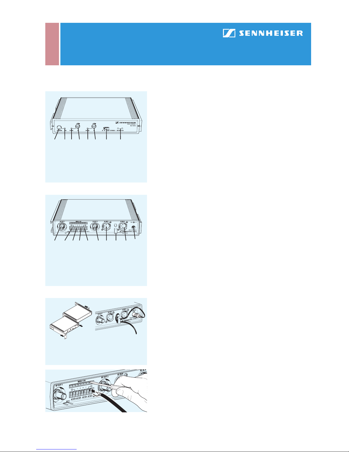
Front panel of the SI 1015
1 On/off switch
2 Mains indicator
3 Peak LED for channel A
4 Level control for
channel A
5 Peak LED for channel B
6 Level control for
channel B
7 Channel selector
switch
8 IR monitoring diodes
1 23 4 5 6 7 8
Back panel of the SI 1015
9 RF output 1 (BNC)
10 RF terminal 1
11 DC output terminal 1
12 DC output terminal 2
13 RF terminal 2
14 RF out put 2 (BNC)
15 Audio input B (XLR-3)
15 Cable grip
17 Au dio inp ut A (XLR-3)
18 DC input socket
(for NT 1015)
9 10 11 12 13 14 15 16 17
18
Mounting the SI 1015 into a rack: the modulator is
combined with a GA 1031 CC blank module to form
a 19“ unit (left), the cable grip prevents the power
cable from being pulled off (right).
Connecting a radiator to the barrier strip of the
SI 1015: Press down a lug with a screwdriver to
open the corresponding terminal
IR Audio Transmission Technology | Modulators/Radiators
 Loading...