

SEI\II\IHEISER
~.FF=
Infrarot-Mono.Leistungssender
Infrared-Mono-Transmitter
Emetteur a,lnfra rouge-Mono
511010
Bedienungsanleitung
OperatingInstructions
Moded'EO1Ploi
Allgemeines
Der Infrarot-Sender SI 1010 dient zur drahtlosen
Ubertragung von Signalen im Tonfrequenzbereich
mittels eines lichtmodulierenden Trägersvon 95 kHz.
Zum Lieferumfang gehören vier Infrarotstrahler Typ
SZI1O10 sowie ein Netzkabel Typ VZN 1010.
Aufstellung
Sender Q) an einem geeigneten Ort (Regieraum,
Beschallungszentrale) aufstellen.
Die vier Strahler@Imittels des an der Unterseite be-
findlichen %"-Gewindes @ auf geeignete .Stative.
oder Halterungen aufschrauben. '.
Strahler so ausrichten, daß das Infrarotlicht gleich-
mäßig den Ubertragungsraum' ausleuchtet. Ab-
schattungen durch Gegenstände und Personen
vermelden I
Verbinden Sie die Strahler paarweise mit den
Leuchtdioden-Ausgängen @ des Senders. Die. Ver-
bindungskabel @ vom Typ GZL 1010 sind von Senn-
heiser electronic als Zubehör getrennt lieferbar.
Werden in bestimmten Fällen nur zwei Strahler
benötigt, so ist jeweils ein Strahler mit,einem Aus-
gang zu verbinden. . .
Inbetriebnahme
Netzstecker @ in 220-V-Netz einstecken.
Gerät durch Eindrücken des Schalters@einschalten.
Die gelbe Leuchtdiode @) zeigt nun die Betriebs-
bereitschaft an.
Kontrollieren, ob in jedem angeschlossenen Strahler
die Funktions-Kontrolldiode@ leuchtet.
Ein e Signalquelle anschließen.
Hochpegelige Signqle (~ischpult, VorversJärker,
Tonbandgeräte) an den Line-Eingang @I,Mikrofone
an den Mic-Eingang @.Für den Betrieb dynamischer
Mikrofone den Schalter @ in Stellung "Dyn.", für
R:ondensator-Mikrofone mit 12-V-Tonaderspeisung
den Schalter in Stellung "Cond." bringen. Bei' ange-
schlossenem Kondensator-Mikrofon leuchtet die
Anzeigendiode ('j) .
Gleichzeitiger Betrieb beider Eingänge ist nicht zu-
lässig, da die Mikrofonbuchseim vorrangbetrieb
arbeitet. Wird ein Stecker in die Buchse @eingeführt,
so wird ein Signal an der Buchse @Ium ca. 40 dB
gedämpft.
Aussteuerung
Mit dem Hubregler @ Wird die t\:10dulationdes Sen-
ders optimal eingestellt. Dies ist erreicht, wenn bei
den lautesten Schallereignissen all e grünen An-
zeigedioden @ aufleuchten und somit der Nennhub
von i: 40 kHz eingestellt ist. Bei weiterer Erhöhung
des E.ingangssignales zeigt die erste rote Diode @
das Uberschreiten des Nennhubes an. Beim Er-
reichen des Spitzenhubes von i: 50 kHz leuchten
beide roten Dioden @.Gleichzeitig begrenzt nun ein
Regelverstärker denSpitzenhub. Obwohl dieser Regel-
verstärker ca. 40 dB Ubersteuerung ohne nennens-
werte Erhöhung des Klirrfaktors ausregelt, wird nicht
empfohlen, den Sender in diesem Bereich zu be-
treiben, daa hierdurch die Dynamik eingeengt wird.
Besondere Betriebsbed!ngungen
Die einwandfreie Infrarot-Ubertragung ist vom Stör-
lichtanteil im Raum und von dessen Größeabhängig.
Bei größeren Räumen (etwa über 200 m2) und zur
Verbesserung des Verhältnisses von Nutzsignal zum
Störlichtanteil kann es notwendig werden. mehrere
Sender parallel zu betreiben. Damit wird dann auch
die Zahl der Strahlereinheiten vervielfacht. Zum
Parallelbetrieb wird mittels eines Synchronkabels
eine Verbindung vom Synchron-A us gang @ des
Muttersenders zum Synchron-Ein g an g @ des
Tochtersenders hergestellt. Insgesamt können auf
diese Weise bis zu drei SendEnzusammengeschaltet
werden. Somit stehen dann im Wiedergaberaum bis
zu 12 Strahler zur Verfügung.
Kabellängen
Die vier zum Lieferumfang gehörenden Strahler SZI
1010 können zur Funk1ionskontrolle direkt 0hne
Verbindungskabel an den Sender angeschlossen
werden. Als Sonderzubehör sind von Sennheiser
electronic die Anschlußkabel GZL 1010@Jmit einer
Länge von 10 m lieferbar. Verbindungskabel können
nach der angegebenen Beschaltung jedoch auch
selbst in den für den Betriebsfall erforderlichen
Längen angefertigt werden. Es ist für die Funktion
des Systems von Bedeutung, daß nur Kabel des
Typs LiYCY
material kann von Sennheiser electronic unter der
. Bezeichnung LV 12-1022 bezogen werden.
Wichtig: Die selbst angefertigten Kabel dürfen die
angegebenen Maximallängen nicht überschreiten.
Störungsfreier Betrieb Ist nur zu erwarten, wenn die
Tabellenwerte eingehalten werden.
Hinweise zum Betrieb mit Mikrofonen
Wir empfehlen, dynamische Mikrofone einzusetzen,
wenn das Mikrofon d ich t besprochen wird (z. B.
Rednerpult etc.). Dazu den Schalter@ für die Speise-
spannung in Stellung "Dyn." bringen! Die Anzeige-
diode für die 12-V-Tonaderspeisung "T 12" leuchtet
dann ni c h t. Der Einsatz von Kondensator-Mikro-
fonen für 12-V-Tonaderspeisung, z. B. MKH 415 T,
wird empfohlen. wenn entferntere Schallereignisse
übertragen werden sollten (z. B. BÜhnenereignisse).
Hierzu den Schalter für die Speisung des Mikrofons
in Stellung "Cond." bringen. Die Anzeigediode T 12 <V
muß bei an g es chi 0 s sen e m Kondensatormikro-
fon leuchten. Durch die richtige Mikrofonwahl werden
Aussteuerprobleme des Senders wirksam vermieden.
4 x 0,25/25 verwendet werden. Kabel-
15
17
.I~
Keme weiteren
Strahler anschließen!
Da not COI1f1ect
further radiators!
Pr- de ne pas
raccorder
de radiateurs
suppeementailOS!
General
The Infrared transmitter SI 1010 serves for wlreless
transmission of audlo signals by means of a light
modulating carrier of 95 kHz The unit is dellvered
with four radiators, type SZI101O and a mains cable,
type VZN 1010.
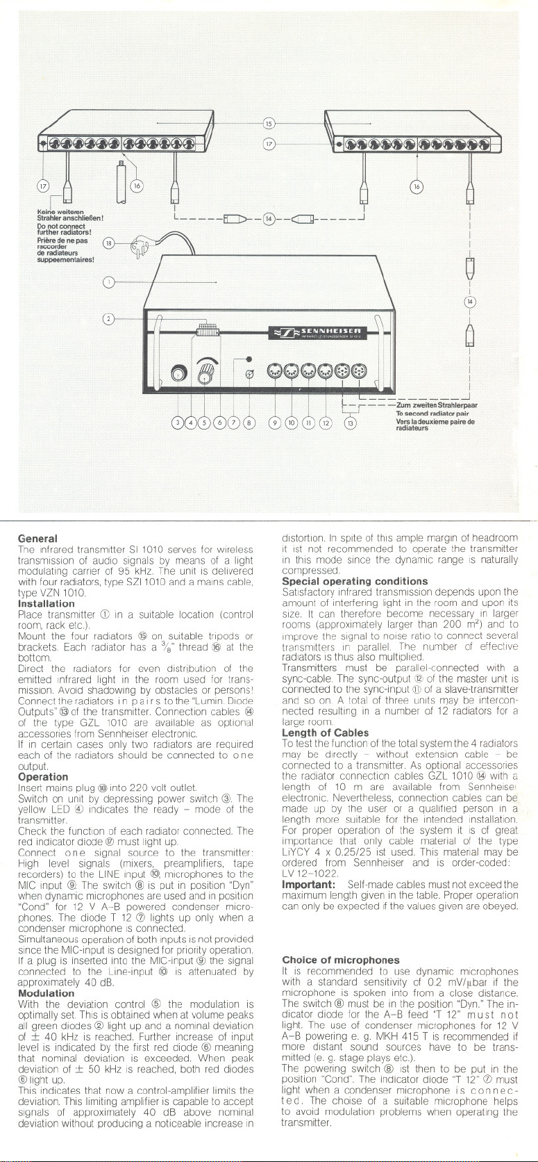
Installation
Place transmitter CDIn a suitable location (control
room, rack etc)
Mount the four radiators @ on suitable tripods or
brackets. Each radiator has a %" thread @ at the
bottom.
Dlrect the radiators for even distribution of the
emitted Infrared light in the room used for trans-
mission. Avoid shadowing by obstacles or persons I
Connect the radiators in pa Ir s to the "Lumin. Diode
Outputs" @of the transmitter. Connection cables @
of the type GZL 1010 are available as optional
accessones from Sennheiser electronic.
If In certain cases only two radiators are required
each of the radiators should be connected to 0n e
output.
Operation
Insert malns plug @ into 220 volt outlet.
Switch on unit by depressing power switch @. The
yellow LED @ indicates the ready - mode of the
transmitter.
Check the functlon of each radiator connected. The
red indicator diode @ must light up.
Connect 0n e signal source to the transmitter
High level signals (mixers, preamplifiers, tape
recorders) to the UNE input @, microphones to the
MIC input @. The sWltch @ is put in position "Dyn"
when dynamic mlCiophones are used and in position
"Cond" for 12 V A~B powered condenser micro-
phones. The diode T 12 Cf) lights up only when a
condenser microphone ISconnected.
Simultaneous operation of both inputs is not provlded
since the MlC-input is designed for prionty operation.
If a plug is inserted into the MIC-input @ the signal
connected to the Line-input @ is attenuated by
approxlmately 40 dB.
Modulation
With the deviation control @ the modulation is
optimally set. This is obtained when at volume peaks
all green diodes @ light up and a nominal deviation
of :f:: 40 kHz is reached. Further increase of input
level is indicated by the first red diode @ meaning
that nominal deviation is exceeded. When peak
deviation of :t 50 kHz is reached, both red dlodes
@ light up
This indicates that now a control-amplifier limits the
deviation. This limiting amplifier is capable to accept
signals of approximately 40 dB above nominal
deviation without producing a noticeable increase in
r 1
L_- ~--~-@--<r:::::]-- - ~_..J
I
f
I
I
I
Q
I
I
@
I
I
e
f
I
I
I
. L J
l
- - - - -Zum zweitenStrahlerpaar
13 Ve'!'ladeuxiemepai.. de
@
distortion In splte of thls ample margln of headroom
It ISt not recommended to operate the transmitter
In thls mode slnce the dynamlc range is naturally
compressed.
Special operating conditions
Satisfactory infrared transmission depends upon the
amount of interferlng light In the room and upon its
size. It can therefore become necessary in larger
rooms (approximately larger than 200 m2) and to
Improve the signal to nOlse ratio to connect several
transmitters In parallel. The number of effectlve
radiators ISthus also multiplied.
Transmitters must be parallel-connected with a
sync-cable. The sync-output @ of the master unit IS
connected to the sync-input @ of a slave-transmitter
and so on. A total of three unlts rTJaybe intercon-
nected resulting in a number of 12 radiators for a
large room.
Length of Cables
T0test the function of the total system the 4 radiators
may be dlrectly - without extension cable - be
connected to a transmitter As optional accessones
the radiator connection cables GZL 1010 @ with a
length of 10 mare available from Sennheise:
electronic Nevertheless, connectlon cables can be
made up by the user or a qualified person in a
length more suitable for the intended installation.
For proper operation of the system it is of great
importance that only cable material of the type
4 x 0.25/25 ist used. This matenal may be
LiYCY
ordered from Sennheiser and IS order-coded:
LV 12-1022.
Important: Self-made cables must not exceed the
maximum length given in the table. Proper operation
can only be expected if the values given are obeyed.
Choice of microphones
It IS recommended to use dynamic microphones
with a standard sensitivity of 0.2 mV/flbar if the
mlcrophone is spoken into from a close distance.
The switch @ must be in the position "Dyn." The in-
dicator diode for the A-B feed "T 12" must not
light. The use of condenser microphones for 12 V
A-B powering e. g. MKH 415 T is recommended if
more distant sound sources have to be trans-
mitted (e. g. stage plays etc.).
The powering switch @ ISt then to be put in the
position "Cond". The indicator diode "T 12" Cf)must
light when a condenser microphone i s co n nec-
ted The choise of a suitable mlcrophone helps
to avoid modulation problems when operating the
transmitter.
Tosecond radiatorpair
rad,ateurs
I

CD Sender
@ Aussteuerdioden grün, für
normalen Betriebsbereich
@ Netzschalter
@) Diode gelb, Betriebsbereitschaft
@) Hubelnsteller
@ Dioden rot, Begrenzereinsatz
(j) Diode rot, Kondensatormikrofon-
Speisung
@ Speise schalter für Kondensator-
mikrofone
@ Mikrofoneingang
@) Leitungseingang
(j]) Synchroneingang
@ Synchronausgang
@ Strahlerausgangsbuchsen
@ Strahleranschlußkabel
@ Infrarotstrahler
@) Gewinde zur Strahlermontage
Diode rot, Funktionskontrolle
@ Netzstecker
Transmitter
LED-chain green, indicators for
normal modulation
Power switch
LED yellow, power indicator
Deviation control
LED's red, start of limiting
LED red, condenser microphone
supply
Switch for condenser mlc. power
Microphone input
Line Input
Sync input
Sync outpvt
Radiator output sockets
Radiator connectlon cable
Infrared radiator
Mountlng thread
LED red, function indicator
Mains plug
Emetteur
Diodes LED vertes indicateurs de
modulation normale de I'emetteur
Interrupteur d'alimentation
Diode LED jaune, Indicateur de
mise en marche
Reglage d'excursion
Diodes LED rouges, seuil de
limitation
Diode LED rouge, alimentation
pour microphones electrostatiques
Commutateur d'allmentation pour
mcros electrostatlques
Entree micro
Entree Iigne
Entree de synchronisation
Sortie de synchronisation
Prise radiateurs
Cables de liaison pour radiateurs
Radiateurs Infrarouges
Filetage pour le montage
des radiateurs
Diode LED rouge, contröle de
fonctionnement
Fiche d'alimentation
Giimeralites
L'emetteur infrarouge SI 1010 permet la transmission
sans filde la basse frequence a I'aide d'une frequence
sous-porteuse de 95 kHz modulant la lumiere infra-
rouge. L'emetteur est livre avec quatre radiateurs
a Infrarouge type SZllOlO et un cable d'alimentation
type VZN 1010.
Installation
Mettre I'emetteur CDa un endrolt convenant (salle de
regie, p. ex.).
Visser les quatre radiateurs @ ades pieds ou
suspensions appropries. Le filetage %" du radiateur
se trouve en face inferieure @ ,
AJuster les radiateurs de manlere a obtenlr un eclai-
rage infrarouge uniforme de la salle prevue pour la
transmission. Eviter la formation d'ombres, causees
per des obJets ou des personnes I
Reller les radiateurs deux a deux aux sorties
« Lumln.
DI(,de Output" @ de !'emetteur. Les cables de
rac:cord@ du type GZL1010 peuvent etre comman-
des separement comme accessoires chez Senn-
heiser electronic
SIdans certains cas on n'utillse que deux radiateurs,
chaque radlateur est a reliera une sortie.
Miseen service
Briincher la fiche d'alimentation @ au reseau 220 V.
Mettre en circuit I'emetteur en enclenchant la
touche GJ.La diode LEDJaune @)s'allume et indique
I'etat de service de I'emetteur.
Controler,SIdans chaque radlateur reliea I'emetteur,
la diode LED rouge @ de controle est allumee.
Brancher une source BF: Les signaux a niveau
fort (pupitre de melange, preamplificateur, magneto-
phones) a I'entree «UNE" @, les mlcrophones a
I'entree «MIC." @ L'utilisatlon de mlcros dyna-
miques necesslte la mise en position «Dyn." du
commutateur@ celle de micros electrostatiques avec
alimentation 12 V a travers les conducteurs de
modulation, la mise en position «Cond.". La diode
LED rouge T 12 Cf!s'allume, si un micro electrostati-
que est branche.
L'utilisation simultanee des entrees «Mic." et« Line"
est prohibee. Le Jack «Mic." travaille en priorite.
Une fiche au Jack «Mic."@ entralne un affaiblrsse-
ment de 40 dB d'un signal a I'entree @
Modulation
L'ajustage
est fait a I'aide du bouton @ Tourner le bouton de
fa<;:on a ce qu'un signal acoustique correspondant
a I'amplitude la plus forte pouvant se produire lors
de la transmission fasse que toutes les diodes
vertes @ s'allument; ce qui correspond a une
excursion nominale de :t 40 kHz. Une augmentation
ulterieure du niveau acoustique est signalee par
I'allumage de la premiere diode LED rouge @
de I'excursion nominale de frequence
L'excurslon de pointe de :t 50 kHz est atteinte, si
les deux dlodes rouges @ so nt allumees.
En meme temps, un amplificateur de reglage limite
I'excursion de frequence a sa valeur de pointe.
L'ampliflcateur est en mesure de regler dessignaux
ayant un niveau de 40 dB au-dessus du niveau nomi-
nal sans pour autant entrainer une augmentation
notable du taux de distorsion. Une operation de
I'emetteur dans cette zone est
compression de dynamique qui s'ensuit.
Conditions speciales d'operation
Le fonctionnement
par rayons infrarouges depend de la lumiere per-
turbatrrce dans la salle choise pour la transmission
et des dimensions de la salle. Dans des salles ayant
une surface superieure a envrron 200 m2 et pour
obtenrr un meilleur rapport signal/bruit il est parfois
necessaire d'avoir en service simultane plusieurs
emetteurs Ceci entralne la multiplicatlon du nombre
de radiateurs. A I'aide d'un cable de synchronisation
on relie la sortle «synchro" @ de I'emetteur pilote a
I'entree «synchro" @ de I'emetteur
Ainsi II est posslble d'avoir en service simultane
jusqu'a trois emetteurs, c. a d. on a a disposition
jusqu'a 12 radiateurs
Longueurs des cäbles
Pour des raisons de controle les quatre radlateurs
1010 livres avec I'emetteur, peuvent etre
SZI
raccordes drrectement a I'emetteur, sans I'inter-
mediaire de cables. Les cables de raccord GZL
1010 @ d'une longueur de 10 m sont livres par
Sennheiser electronlc comme accessoires. liest
posslble de
sans defaut de la transmission
faire les cables soi-meme d'apres le
a deconseiller vu la
secondaire.
schema indique plus bas avec une longueur con-
venant au mode d'operation. Pour le bon fonctionne-
ment de I'ensemble il est important de n'employer
que des cables du type LiYCY 4 x 0,25/25. Ces
cables peuvent etre commandes chez Sennheiser
electronic
Important: Priere de ne pas depasser les longueurs
maximales indiquees. Un fonctionnement correct
n'est possible qu'en respect des valeurs du tableau.
Choix des microphones
Nous conseilIons I'emploi de micros dynamiques
si les mcros se trouvent a proximitede la source
sonore (p. ex. conferencier). Mettre le commuta-
teur @ en position «Dyn.'" La diode T 12 7 reste
eteinte.
alimentation 12 V a travers les conducteurs de
sous la designation LV12-1022.
L'usage de micros electrostatiques a
modulation, p. ex. MKH415 Test recommande, si
la source sonore est eloignee (p. ex. theatre). Le
commutateur @ est
diode T 12 Cf! s'allume des que le micro est
branche. Le choix correct des micros evite les
problemes de modulation de I'emetteur.
amettreen position « Cond. " La

Betrieb am 110-V-Netz
Der SI 1010 wird ab Werk für den Betrieb am 220-V
Wechselstromnetz geliefert. Soll das Gerät am
110-V-Netz betrieben werden, so ist es auf folgende
Welse umzustellen:
1. Die zwei Schrauben der Rückwand lösen und
Chassis nach vorne aus dern Gehäuse heraus-
ziehen.
2. Plastik-Abdeckkappe auf der Platine in der Nähe
des Netzschalters entfernen.
3. Lötbrücken-Anschluß von ,,220 V" entfernen und
auf ,,11O-V"-Punkt löten.
4. Gerät in umgekehrter Reihenfolge wieder mon-
tieren.
Voltage conversion for 110 V-lines
The unit is delivered ready for use on 220 V power
lines. It may be easily converted to operate on 110V
lines:
1. Loosen the two screws on the rear and pull 0
the chassis towards thr front.
2. Remove plastic cover on circuit board near tt
power switch.
3. Remove solder bridge from "220 V" point al
solder to "110V" point.
4. Mount unit in reverse order.
Alimentation 110 V
Le SI 1010 est normalement livre pour une alimenta
tion de 220 V. Le changement Eifaire pour um
alimentation 110V se fait comme suit:
1. Desserrer le panneau arriere Ei I'aide des 2 vis
Retirer le chassis du boltier vers I'avant.
2. Enlever les couvertures en matiere plastique dl
commutateur d'alimentation.
3. Enlever laconnexion de soudure du point« 220 V,
et la souder au point «110 V".
4. Faire le montage en sens inverse.
SEI\II\IHEISER
~.FI==
Sennheiserelectronic. 3002 Wedemark2
Drahtwort: Sennheiser Bissendorfhann.
'&"MeIlendorf (05130) 8011
Sendefrequenz.
I Modulation. .. .. ..
~ Pegelhub,externeinstellbar
Spitzenhub. .
Hubanzeige. .. . .. . . .. . .. . . .
Störhub Mikrofoneingang
Leitungseingang ..
Eingänge
1. Mikrofoneingang ... ... ... ... ....
Empfindlichkeitfür40 kHzHub .. .
abschaltbareSpeisespannungfürKondensatormikrofone
Impedanz
Ubersteuerbarkeit
; 2. Leitungseingang.
Kontaktbelegung
Empfindlichkeit.
l.mpedanz .. ... .. ...
Ubersteuerbarkeit
3. Synchroneingang.
Kontaktbelegung
Empfindlichkeit.. ....
Eingangswiderstand
Ausgänge
1 Synchronausgang.
Kontaktbelegung
Nennpegel. . .....
Innenwiderstand
2. Strahlerausgänge
Nennstrom (Gleichstrommittelwert)
Leerlaufspannung.
Stromform
Begrenzerverstärker .......
Einsatz (intern eingestellt) .
Dyn.<'lmikbereich ....................
NF-Ubertragungsbereich (:t 3 dB) ......
Klirrfaktor bei 1000 Hz und 40 kHz Hub
Spannungsversorgung
Leistungsaufnahme. ..
Abmessungen in mm
Gewicht.. . .. .. ..........
.........
95 kHz
FM,Preemphasis50 ~s
:t 40 kHz
:t 50 kHz
Leuchtdiodenzeile
< 125 Hz
< 70 Hz
N-Beschaltung DIN 45594
0.5 mV
12 V nach DIN 45595
N: > 500 Q (50 Hz . . . 15 kHz)
> 1000 Q (100 Hz. . . 10 kHz)
T 12: 360 Q nach DIN 45595
ca. 35 dB
5pol. Stereo-Normbuchse
3 ~ NF, 2 ~ Masse
+ 6 dBm (1,55 V)
ca 70 kQ
ca. 40 dB
5pol. Stereo-Normbuchse
1~ HF, 4. 2, 5 ~ Masse
2 Vss
> 2 kQ
5pol. Stereo-Normbuchse
1~ HF, 2, 4. 5 ~ Masse
2 Vss
6,8 kQ
2 Stück, 6pol. Buchse nach DIN 45322,
Endstufenstromrichtung 1 -2, 5 -4,
3 ~ Masse,Schirm
ca. 130 mA
ca. 30 Vso
sinusförmig
Zwei-Zeitkonstanten-Schallung mit FET
:t 50 kHz Hub
ca. 40 dB werden auf 1 dB begrenzt
20 Hz. . 20 kHz
<1%
220 V, 50-60 Hz (110V umlötbar)
ca. 35 W
ca. 295 x 173 x 97
ca. 5 kg
Printed in W.-Germany Pub!. 9/76

Kabeltyp Verbindung Max. Länge
Cable type
Type de cäble
Connection
Raccordement
in Metern
Max. length
in meter
Longueur max. Designation
en metres
Kabelmaterial
Cable material
Strahleranschlußkabel Sender -+ Strahler
Radiator connection cable Transmitter -+ Radiator
Cäble de raccordement pour radiateurs
Verbindungskabel
Emetteur -+ Radiateur 15
Strahler -+ Strahler
Radiator connection cable Radiator -+ Radiator
Cäble de raccordement pour radiateurs
Synchronkabel
Sync-cable
Cäble de synchronisation
Radiateur -+ Radiateur
Sender -+ Sender 100
Transmitter-+ Transmitter 100 LiYCY 4 x 0.25/25
Emetteur -+ Emetteur
100
Mikrofonkabel Mikrofon -+ Sender 100
Microphone-cable Microphone -+ Trans-
Cäble de micro
Line-Eingang
Line-input High level
Entree ligne
mitter screened cable
Micro -+ Emetteur
Hochpegelige
Quelle -+ Sender
source -+ Transmitter
Source a niveau 100
fort -+ Emetteur
100
100
100
100
15
LiYCY 4 x 0,25/25
15 LiYCY 4 x 0.25/25
LiYCY 4 x 0,25/25
15
LiYCY 4 x 0,25/25
15 LiYCY 4 x 0.25/25
15
LiYCY 4 x 0,25/25
LiYCY 4 x 0,25/25
LiYCY 4 x 0,25/25
Beliebig, hochwertige
2adrig abgeschirmte
Leitung
Any high quality 2-lead
Au choix, cäble blinde
a 2 conducteurs,
de haute qualite
Beliebig, hochwertige
1adrig abgeschirmte
Leitung
Any high quality 1-lead
screened cable
Au choix, cäble blinde
a 1 conducteur,
de haute qualite
Transmission frequency
Modulation .. ... ... ... ... ... ... ... ...
Nominal deviation, extemal controllable
Peak deviation. .... .. . .. .. ..
Modulation control . .. .. ..
Noise deviation Microphone input.
Une-input
Inputs
1. Microphone input. ...... . .. .....
Sensitlvlty lor 40 kHz deviation. . ... ...........
Power lor condenser microphones switchable .
Impedance ...
Overload range.
2. Line Input.......
Pin connections........
Sensitlvity ..
Impedance ......
Overload range.
3. Sync-input......
P,n connections
Sensitlvlty ... .
Inpul impedance
Outputs
1. Sync-output. ..
Pin connections. ....
Nominal level.. ..
Source impedance
2. Radiator outpuls.
Nominalcurrent(averageDCcurren!).
Voltagewithoutload. .. ....
Wavelorm01current. .. .. ..
Limitingamplilier .......................
Start01limiting(intemallyset) .......
Dynamic range. . . . . . . . . . . . .. . . . . . . . . . . .
Audio frequency response (:t 3 dB) ...
THD at 1000 Hz and 40 kHz deviation.
Line voltage.. .. ... ...
Current consumption
Dimensions in mm..........
Weight.
.. . .........
......
95 kHz
FM.preemphasis50 I's
:t 40 kHz
:t 50 kHz
LED-chainindlcator
< 125Hz
< 70 Hz
N-wlring DIN 45594
0.5 mV
12 V to DIN 45595
N: > 500 Q (50 Hz. . . 15 kHz)
> 1000 Q (100 Hz. . . 10 kHz)
T 12: 360 Q to DIN 45595
appx. 35 dB
5-pin stereo-DIN plug
3~ audio, 3 ~ ground
+ 6 dBm (1.55 V)
appx. 70 kQ
appx. 40 dB
5-pin stereo-DIN plug
1~ RF,4, 2,5 ~ ground
2 Vpp
> 2 kQ
5-pin Stereo-DIN plug
1~ RF,2,4, 5 ~ ground
2 Vpp
6.8Q
Two, 6-pin connector to DIN 45322. current
flow of power stage from pin 1 -2,
5-4, 3 ~ ground, screen
appx. 130 mA
appx. 30 Vp
sinusoidal
Two-timeconstant-circuit with FET
:t 50 kHz deviation
approx. 40 dB are limited to 1 dB
20 Hz. . 20 kHz
<1%
220 V,50-60 Hz (110 V convertable)
appx. 35 W
appx. 295 x 173 x 97
appx. 5 kg

Beschaltung der Anschlußkabel und Eingangsbuchsen:
Wiring of connection cables and input sockets:
Schema de branchement des cables de raccordement et des
prises d'entree:
I ~I
i~ A1i
IV
L ~
Mak50 Mas50
Strahleranschlußkabel
Radiator connection cable
Cäble de raccordement pour
radiateurs
1 1
ilh Ai
i'fV "fli
L J
Mas 50 S Mas 50 S
Synchronkabel
Sync-cable
Cäble de synchronisation
'ffi
NF, Speisung (B
Audio, Cond. power (B
BF, Alimentation (B
symmetrisch
baianced
symetrique
NF, Speisung e
Audlo, Cond. power e
BF, Alimentation e
Beschaltung des Mikrofon-Eingangs
Wiring of microphone input
Schema de branchement de
I'entree-micro
unsymmetrisch
unbalanced
Ecran,
Masse
Beschaltung des Une-Eingangs
Wiring of Une-input
Schema de branchement de
I'entree ligne
NF,+ 6 dB
Audlo,+ 6 dB
BF,+ 6 dB
asymetrique
Frequence porteuse .
Modulation .. .. .
Excurslon normale, reglable exterleurement
Excursion maximale de crete
Controle de modulation - . .. . ..
Excurslon paraslte Entree mlcro
Entrees
1 ~~~m=. .. ................
Sensibllite pour une excurSlon de :t 40 kHz . ........
Alimentation pour micros electrostatlques, deconnectable
Impedance .
Plage du surmodulatlon
2. Entree Iigne .
Branchement
SenslbHlte ..
Impedance ........
Plage de surmodulation
3. Entree synchronisation
Branchement
Senslbllite ............
Impedance d'entree
Sorties
1 Sortle synchronisation
Branchement ..
Niveau nominal.
Impedance de sortle
2. Sortles radlateurs
Courant nominal (valeur moyenne du courant continu)
Tension avide . .
Configuration du courant
Amplificateur limteur .
SeuHde.limltation (ajuste Interieurement)
Plage du limiteur. ....
Reponse SF (:t 3 dB) . .. ... . . .... ...... . ...
Distorslonharmonique pour 1 kHz et 40 kHz d'excurslon
Alimentation ..
Consommation sur secteur
Dimensions en mm
POlds.
Entree ligne
95 kHz
FM, preaccentuatlon 50~s
:t 40 kHz
:t 50 kHz
Indlcateur LED
< 125 Hz
< 70 Hz
Branchement N, DIN 45594
0,5 mV
12 V selon DIN 45595
N > 500 Q (50 Hz . . . 15 kHz)
> 1000 Q (100 Hz. . . 10 kHz)
T 12: 360 Q seion DIN 45595
appx. 35 dB
Prise 5 broches normalisee stereo
3 ~ BF, 2 ~ masse
+ 6 dBm (1,55 V)
appx. 70 kQ
appx. 40 dB
Prise 5 broches normallsee stereo
1 ~ HF, 4, 2, 5 ~ masse
2 Vpp
> 2 kQ
Prise 5 blOches normalisee stereo
1~ HF, 2, 4, 5 ~ masse
2 Vpp
6,8 Q
deux, prise 6 broches selon DIN 45322,
sens du courant de I'etage de sortie,
1 ~ 2, 5 ~ 4, 3 ~ masse, ecran
appx. 130 mA
appx. 30 Vpo
sinusoldale
Clrcuit a 2 constantes de temps avec
etage FET
:t 50 kHz d'excursion
appx. 40 dB sont ramenes a 1 dB
20 Hz. . 20 kHz
<1%
220 V, 50-60 Hz (Inversion a 110 V)
appx. 35 W
appx. 295 x 173 x 97
appx. 5 kg
 Loading...