

Page 1

Bedienungsanleitung
Instructions for use
Notice d‘emploi
Istruzioni per l‘uso
Instrucciones de uso
Gebruiksaanwijzing
L 151-10
Page 2

2
Page 3

L 151-10
Ladeleiste zum Laden von maximal 10 Kinnbügel-Empfängern. Folgende Empfänger
(mit eingelegtem Akku BA 151) können in dieser Ladeleiste geladen werden:
• RI 150 • RI 300
• RI 250 • RI 500
• HDI 302
Es besteht auch jeweils die Möglichkeit, an Stelle eines Höres einen einzelnen Akku
BA 151 im Fach zu laden.
Anschluß
Die Ladeleiste L 151-10 ist an der Frontseite mit einer Buchse zum Anschluss der
Netz-teile NT 92 oder NT 2013 ausgerüstet. Für einzelne Ladeleisten ist das NT 92
vorgesehen, für 2-5 kaskadierte Leisten das größere Netzteil NT 2013. Bitte keine
einzelnen Ladeleisten am NT 2013 betreiben.
Inbetriebnahme
Steckernetzteil in die Steckdose stecken. Anschluss zur Ladeleiste herstellen. Nach
ca. zwei Sekunden leuchtet die rote LED "CHARGE ", das Gerät ist betriebsbereit.
Beim Einstecken der Stromversorgung wird automatisch auf Ladung (8 h) geschaltet.
Die Kontroll-LED‘s an den belegten Ladefächern zeigen die Ladung zusätzlich an.
Nach Beendigung des Ladevorganges schaltet die Ladeleiste automatisch auf Erhaltungsladung um. Dabei leuchtet die grüne LED „TRICKLE CHARGE“, die roten LEDs
an den belegten Ladefächern leuchten nur noch schwach.
3
Page 4

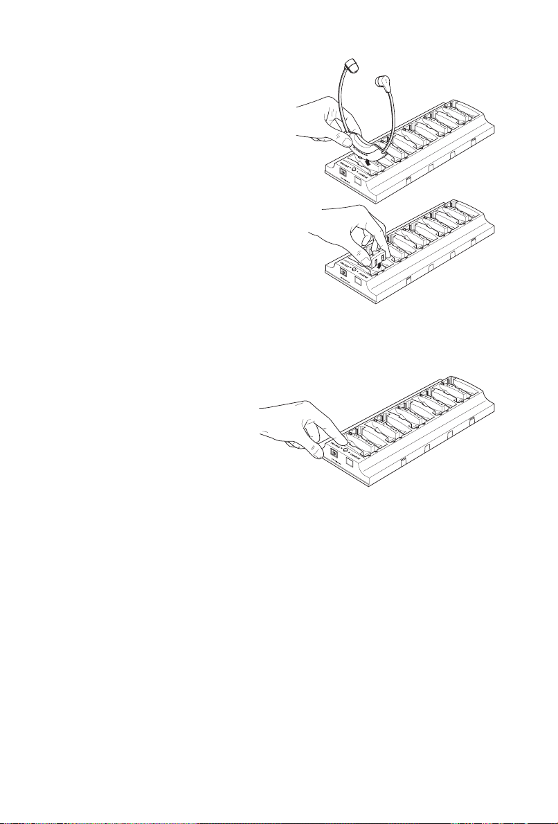
Laden
• Zum Laden die Empfänger in die
Ladeschächte einstecken.
• Einzelne Wechselakkus BA 151 werden
alternativ in den zusätzlichen seitlichen
Ladeschächten geladen. Es kann aber nur
entweder ein Akku oder ein Hörer mit
eingelegtem Akku geladen werden.
Ladung starten
Der Normal-Ladevorgang wird durch
die Taste gestartet. Dabei verlischt
kurz die rote LED, der Ladevorgang
wird durch rotes Licht der KontrollLED‘s an den belegten Ladefächern
angezeigt. Die Ladung erfolgt
automatisch (zeitgesteuert) und ist
nach 8 Stunden beendet. Danach
schaltet das Gerät auf Erhaltungsladung um.
Wichtige Hinweise
• Der Ladevorgang (“CHARGE“) kann nicht unterbrochen werden. Weitere Betätigung
der Taste setzt die Zeitschaltung zurück, der Ladevorgang startet von neuem.
• Auch ein Netzausfall setzt die Zeitschaltung zurück. Der Ladevorgang startet auch
hier von neuem.
• Die Empfänger müssen vor der Ladung ausgeschaltet werden! Weitere
Bedienungshinweise zu den Empfängern entnehmen Sie bitte den entsprechenden Gebrauchsanleitungen.
• Ladeleiste L 151-10 bitte auf einer waagerechten Fläche aufstellen, damit die Kontakte in den Hörern sicher in der Ladeleiste aufliegen!
4
Page 5
Mehrere Ladeleisten zusammenschalten
Mit den Metallschienen im Sockel können mehrere Ladeleisten zusammengeschaltet
werden. Die Stromversorgung erfolgt dann durch ein gemeinsames Steckernetzteil:
• bei einer Ladeleiste ist ein Steckernetzteil NT 92 ausreichend
• maximal fünf Ladeleisten werden von einem Steckernetzteil NT 2013 versorgt.
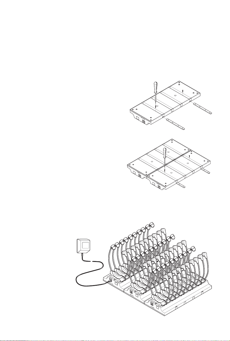
Zusammenbau
Lösen Sie zunächst die Schrauben
und entfernen Sie bitte die
Kaskadierschienen.
Kaskadieren
Zwei oder mehrere Ladeleisten
werden nun durch die Schienen
miteinander verbunden.
Schrauben wieder einsetzen und
festziehen.
In dieser Beispielabbildung sind drei
Ladeleisten miteinander verbunden.
30 Hörer oder entsprechend viele
Akkus können dort geladen und
aufbewahrt werden.
NT 2013
3 x L 151-10
5
Page 6

Technische Daten
Anzahl der Ladefächer 10
Ladestrom bei Normalladung ca. 10 mA
Ladestrom bei Erhaltungsladung ca. 2 mA
Ladezeit der Empfänger (Normalladung) ca. 8 Stunden
Stromversorgung 12 Volt DC aus NT 92 / NT2013
Gewicht ohne Empfänger und Netzteil ca. 400 g
Abmessungen in mm 325 x 98 x 42
Lieferumfang
• 1 Ladeleiste L 151-10
• 2 Kaskadierschienen mit Schrauben (an der Unterseite montiert)
abgebildete Kinnbügel-Empfänger und Netzteile sind nicht im
Lieferumfang enthalten.
Lieferbare Netzteile:
für die Versorgung von einer Ladeleiste L 151-10
• NT 92 230 V, 50-60 Hz Art. Nr. 003357
• NT 92-120 120 V, 50-60 Hz Art. Nr. 003358
• NT 92 UK 240 V, 50-60 Hz Art. Nr. 003359
für die Versorgung von zwei bis fünf Ladeleisten L 151-10
• NT 2013 230 V, 50-60 Hz Art. Nr. 003433
• NT 2013-120 120 V, 50-60 Hz Art. Nr. 003434
• NG 2013 UK 240 V, 50-60 Hz Art. Nr. 054332
Ersatzakku für Kinnbügel- /Kopfhörerempfänger
• BA 151 Art. Nr. 04146
6
Page 7

L 151-10
Charging unit for recharging up to 10 stethoset receivers. The L 151-10 is suitable for
the following stethoset receivers (containing a BA 151 accupack):
• RI 150 • RI 250
• RI 300 • RI 500
• HDI 302
Instead of charging a receiver, it is also possible to charge an individual BA 151
accupack in a charging compartment (e.g. HDI 380).
Power supply
The front of the L 151-10 charging unit features a socket for connection of the NT 92
or NT 2013 mains unit. Use the NT 92 mains unit for powering a single charging unit
or the NT 2013 mains unit for powering two to five cascaded charging units. Do
use the NT 2013 for powering a single charging unit!
not
Putting the charging unit into operation
Connect the mains unit to the socket on the charging unit, then plug the mains
connector into the mains. After approx. two seconds, the red LED („CHARGE“) lights
up and the charging unit is ready for operation.
As soon as the charging unit is connected to the mains, the device automatically
switches to normal charging (8 hours). The charging process is indicated by the control
LEDs at the occupied charging compartments. After a charging time of 10 hours, the
charging unit automatically switches to trickle charging. The green LED („TRICKLE CHARGE“) lights up and the red control LEDs at the charging compartments dim (bright = normal charge, dim = trickle charge).
7
Page 8
Charging a stethoset receiver/ spare accupack
• Insert the receivers into the
charging compartments of the
L 151-10, the accupacks remain in
the receivers.
• Alternatively, individual
BA 151 spare accupacks can be
charged in small charging
compartments integrated into the
side of the main charging
compartments for the receivers.
However, it is only possible to
insert either an individual
accupack or a receiver containing
an accupack into the charging
compartment (not both
together).
Starting the charging process
By pressing the button, the „normal“
charging process begins. The red LED
goes off briefly and the charging
process is indicated by the red control
LEDs at the occupied charging compartments. The automatic charging
process (timer-controlled) will be
completed after 8 hours. The device
then switches to trickle charging.
Essential notes
• The charging process („CHARGE“) cannot be interrupted. By pressing the button again,
the charging timer is reset and the charging process starts over again.
• A power failure also resets the charging timer and the charging process starts
over again.
• Switch off the receivers before starting the charging process! For additional
information on the use of the receivers, please refer to the corresponding operating
instructions.
• Place the charging unit on a flat surface in order that the contacts of the receivers
are securely connected to the charging unit.
8
Page 9

Cascading several charging units
Several charging units can be cascaded together with the metal rails mounted at the
bottom of each charging unit. The charging units are then powered by a common mains
unit:
• A single charging unit can be powered by the NT 92 mains unit
• Up to five charging units can be powered by the NT 2013 mains unit
(N.B.:Do not use the NT 2013 for a single charging unit!)
Unscrew the screws and slide out
the rails. With the rails half out,
reinsert two screws and screw them
tight. Slide on the second unit (with
rails removed), reinsert the other
two screws and tighten them.
Repeat for further units (see
diagram).
The illustration on the right shows
three cascaded charging units. 30
stethoset receivers or the
corresponding number of accupacks
can be recharged and stored.
NT 2013
3 x L 151-10
9
Page 10

Technical data
Charging compartments 10
Charging current at „normal“ charge approx. 10 mA
Charging current at trickle charge approx. 2 mA
Charging time („normal“ charge) approx. 8 h
Power supply 12 V DC via NT 92 / NT 2013
Weight(w/o receivers and plug-in mains units) approx. 400 g
Dimensions in mm 325 x 98 x 42
Supply schedule
• 1 L 151-10 charging unit
• 2 rails with screws (mounted at the bottom of the charging unit)
for cascading several L 151-10
The stethoset receivers and mains units
are not included in the supply schedule!
Available mains units
For powering one L 151-10 charging unit:
• NT 92 230 V, 50–60 Hz Cat. no. 003357
• NT 92-120 120 V, 50–60 Hz Cat. no. 003358
• NT 92-UK 240 V, 50–60 Hz Cat. no. 003359
For powering two to five L 151-10 charging units:
• NT 2013 230 V, 50–60 Hz Cat. no. 003433
• NT 2013-120 120 V, 50–60 Hz Cat. no. 003434
• NG 2013-UK 240 V, 50–60 Hz Cat. no. 054332
Spare accupack for stethoset receivers
• BA 151 Cat. no. 04146
10
Page 11

L 151-10
Réglette de recharge pour recharger jusqu’à 10 récepteurs stéthoscopiques. La réglette
de recharge L 151-10 permet la recharge des récepteurs stéthoscopiques suivants
(avec accu BA 151 inséré):
• RI 150 • RI 250
• RI 300 • RI 500
• HDI 302
Il est également possible de recharger un accu BA 151 séparé dans un compartiment
de recharge. Dans ce cas, il n’est pas possible de recharger un récepteur en mème
temps.
Alimentation
La partie frontale de la réglette de recharge L 151-10 est pourvue d’une prise pour le
branchement d’un bloc-secteur NT 92 ou NT 2013. Pour alimenter une seule réglette
de recharge, utiliser le bloc-secteur NT 92, pour alimenter deux à cinq réglettes de
recharge branchées en chaîne, utiliser le bloc-secteur plus puissant NT 2013. Ne jamais
alimenter une seule réglette de recharge par le NT 2013 !
Mise en service
Brancher le bloc-secteur dans la prise secteur et établir la liaison avec la réglette de
recharge. Après environ deux secondes, la LED rouge „CHARGE“ s’allume et l’appareil
est prêt à fonctionner.
En branchant le bloc-secteur, l’appareil démarre automatiquement en charge
(8 heures). Le processus de recharge est signalé par l’allumage des LEDs de contrôle
au niveau des compartiments de recharge occupés. Apr s la recharge, l’appareil
retourne automatiquement en charge d’entretien. La LED verte „TRICKLE CHARGE“
s’allume et l’allumage des LEDs rouges au niveau des compartiments de recharge
s’affaiblit.
è
11
Page 12

Charge des récepteurs stéthoscopiques/des accus
• Pour la recharge, enficher les
récepteurs dans les
compartiments de recharge.
• Des accus BA 151 séparés
peuvent être rechargés dans les
compartiments de recharge
supplémentaires intégrés à côté
des compartiments de recharge
pour récepteurs. Dans ce cas, il
n’est pas possible de recharger un
récepteur en même temps.
Un compartiment de recharge
permet de recharger soit un accu
séparé, soit un récepteur
stéthoscopique avec accu inséré.
Démarrer la charge
Appuyer la touche pour démarrer la
charge en mode „normal“. La LED
rouge s’éteint brièvement et le
processus de recharge est signalé par
l’allumage des LEDs rouges de contrôle
au niveau des compartiments de
recharge occupés. La recharge s’effectue
automatiquement (de manière
temporisée) et s’ach ve au bout de
8 heures. L’appareil retourne ensuite en
charge d’entretien.
è
Remarques importantes
• Le processus de recharge („CHARGE“) ne peut pas être interrompu. Si vous appuyez
de nouveau la touche, le fonctionnement du temporisateur est annulé et le
processus de recharge recommence à zéro.
• Une panne de secteur annule également le fonctionnement du temporisateur. Le
processus de recharge recommence à zéro.
• Eteindre les récepteurs lors de la recharge ! Pour de plus amples informations sur
les récepteurs, veuillez consulter les notices d’emploi respectives.
• Placer la réglette de recharge sur une surface horizontale afin que les contacts
des récepteurs soient bien reliés à la réglette de recharge.
12
Page 13

Relier plusieurs réglettes de recharge
Les rails de fixation dans la base de la réglette de recharge permettent de relier
plusieurs réglettes de recharge. L’alimentation s’effectue par un bloc-secteur commun:
• Une réglette de recharge peut être alimentée par un bloc-secteur NT 92
• Jusqu’à cinq réglettes de recharge peuvent être alimentées par un bloc-secteur NT
2013. Ne jamais alimenter une seule réglette de recharge par le NT 2013 !
Assemblage
Dévisser les vis et retirer les rails.
Montage en chaîne
Relier deux ou plusieurs réglettes de
recharge à l’aide des rails.
Réinsérer les vis et les revisser à
fond.
L’illustration ci-contre montre trois
réglettes de recharge reliées.
30 récepteurs stéthoscopiques ou le
nombre correspondant d’accus
peuvent y être rechargés et logés.
NT 2013
3 x L 151-10
13
Page 14

Caractéristiques techniques
Compartiments de recharge 10
Courant de charge, charge en mode „normal“ approx. 10 mA
Courant de charge, charge d’entretien approx. 2 mA
Temps de recharge (charge en mode „normal“) approx. 8 heures
Alimentation 12 V DC par NT 92 / NT 2013
Poids (sans bloc-secteur et récepteurs) approx. 400 g
Dimensions en mm 325 x 98 x 42
Contenu
• 1 réglette de recharge L 151-10
•
2 rails de fixation avec vis (montés la partie inférieure)
pour relier plusieurs L 151-10
Les récepteurs stéthoscopiques et
blocs-secteur illustrés ne sont pas inclus !
à
Blocs-secteur disponibles
Pour l’alimentation d’une seule réglette de recharge L 151-10
• NT 92 230 V, 50–60 Hz N° Réf. 003357
• NT 92-120 120 V, 50–60 Hz N° Réf. 003358
• NT 92-UK 240 V, 50–60 Hz N° Réf. 003359
Pour l’alimentation de deux à cinq réglettes de recharge L 151-10
• NT 2013 230 V, 50–60 Hz N° Réf. 003433
• NT 2013-120 120 V, 50–60 Hz N° Réf. 003434
• NG 2013-UK 240 V, 50–60 Hz N° Réf. 054332
Accu supplémentaire pour récepteur stéthoscopique
• BA 151 N° Réf. 04146
14
Page 15

L151-10
Base di ricarica per 10 ricevitori sottomento. Possono essere ricaricati i seguenti
ricevitori (con l‘accumulatore BA 151 inserito):
• RI 150 • RI 300
• RI 250 • RI 500
• HDI 302
E‘ anche possibile ricaricare il solo accumulatore BA 151.
Collegamento
La base di ricarica L151-10 presenta sul lato frontale una presa per il collegamento
con gli alimentatori NT 92 o NT 2013. Per le basi di ricarica singole è previsto il NT 92;
per l‘alimentazione da 2 a 5 basi di ricarica collegate in cascata, è necessario utilizzare
l‘alimentatore NT2031.
Messa in funzione
Collegate l‘alimentatore alla presa di corrente. Effettuate il collegamento alla base di
ricarica. Dopo circa due secondi si accenderà il LED rosso.
Con l‘alimentazione viene automaticamente attivata la fase di ricarica (8 ore). Anche
i LED di controllo dei vani di ricarica occupati visualizzano che è in corso la ricarica.
Quando la procedura di ricarica è terminata, viene automaticamente attivata la
funzione di mantenimento della carica. In questo caso si illumina il LED verde „Trickle
Charge“, e il colore dei LED rossi dei vani di ricarica sarà più debole.
15
Page 16

Ricarica
• Inserire i ricevitori nei vani di
ricarica della base.
• I singoli accumulatori BA 151
possono essere caricati in
alternativa inserendoli nei vani
di ricarica laterali. Potete perė
solo caricare un accumulatore o
un ricevitore con il proprio
accumulatore inserito.
Avvio della ricarica
La procedura normale di ricarica
viene attivata attraverso il tasto. Il
LED rosso si spegne brevemente, la
procedura di ricarica viene indicata
attraverso i LED rossi dei vani di
ricarica occupati. La ricarica avviene
automaticamente (regolato a
tempo) termina dopo 8 ore.
Successivamente, la base di ricarica
attiva la funzione di mantenimento
della carica.
è
Note importanti:
• La procedura di ricarica („CHARGE“) non puė essere interrotta. Se viene
nuovamente premuto il tasto, il tempo viene azzerato e la procedura di ricarica
ricomincia.
• Anche la mancanza di corrente azzera il tempo. La procedura di caricamento inizia
nuovamente.
• I ricevitori devono essere spenti prima di ricaricarli! Per ulteriori istruzioni per l‘uso
dei ricevitori, Vi preghiamo di consultare il relativo manuale delle istruzioni.
• La base di ricarica deve essere posta su una superficie orizzontale per assicurare
che i contatti dei ricevitori siano inseriti in modo sicuro nella base di ricarica.
16
Page 17

Collegamento di più basi di ricarica
Attraverso gli opportuni contatti metallici si possono collegare tra di loro più basi.
L‘alimentazione avviene attraverso una presa comune.
• in caso di una base di ricarica è sufficiente l‘alimentatore NT 92
• con un alimentatore NT 2013 possono essere alimentate fino a cinque basi
Assemblaggio
Svitate le viti e togliete le guide.
Montaggio a cascata
Due o più basi di ricarica possono
essere collegate tra loro attraverso
le guide.
Inserite nuovamente le viti e
accertatevi del corretto
avvitamento.
In questo disegno sono per esempio
collegati tra di loro tre basi di
ricarica. Qui possono essere caricati
e custoditi 30 ricevitori o lo stesso
numero di accumulatori.
NT 2013
3 x L 151-10
17
Page 18

Dati tecnici
Numero dei vani di ricarica 10
Consumo in caso di ricarica normale ca. 10 mA
Consumo in caso di mantenimento della carica ca. 2 mA
Tempo di ricarica dei ricevitori (normale)
Alimentazione 12 Volt DG dal NT 92 / NT 2013
Peso senza ricevitori e alimentatore ca. 400g
Dimensioni in mm 325 x 98 x 42
ca. 8 ore
Dotazione
• 1 base di ricarica L151-10
• 2 guide per il collegamento a cascata con le viti
(montate nella parte inferiore)
I ricevitori sottomento e alimentatori
indicati nei disegni sono accessori.
Alimentatori disponibili
per l‘alimentazione di una base di ricarica L 151-10
• NT 92 230 V, 50-60 Hz Art.003357
• NT 92 120 120 V, 50-60 Hz Art.003358
• NT 92 UK 240 V, 50-60 Hz Art.003359
per l‘alimentazione di due fino a cinque basi di ricarica L 151-10
• NT 2013 230 V, 50-60 Hz Art.003433
• NT 2013-120 120 V, 50-60 Hz Art.003343
• NG 2013 UK 240 V, 50-60 Hz Art.054332
Accumulatori di ricambio per ricevitori sottomento/ cuffie
• BA 151 Art. 04146
18
Page 19

L151-10
Regleta de carga para cargar hasta un máximo de 10 receptores de barbilla. En esta
regleta de carga pueden cargarse los receptores siguientes (con pila BA 15 incluida):
• RI 150 • RI 300
• RI 250 • RI 500
• HDI 302
También se tiene la posibilidad de cargar una sóla pila BA 151 en lugar de un auricular.
Conexión
La regleta de carga L 151-10 lleva un jack en la parte frontal para la conexión de los
transmisores de mando NT 92 ó NT 2013. El NT 92 está concebido para regletas de
carga individuales y el transmisor de mando mayor NT 2013 para 2-5 regletas
dispuestas en cascada. No usar las regletas de carga individuales para el NT 2013.
Puesta en servicio
Insertar el enchufe macho en la caja de pared. Establecer la conexión a la regleta de
carga. Después de unos dos segundos se ilumina el diodo LED „CHARGE„ y el aparato
está listo para el servicio.
Al insertar el abastecimiento de corriente, conmuta automáticamente a carga (8 h).
Los diodos de control LED situados en los compartimientos de carga ocupados, indican
adicionalmente el estado de carga.
Una vez finalizdo el proceso de carga, la regleta conmuta automáticamente a carga
de sostén. Entonces luce el diodo verde LED „TRICKLE CHARGE“ y los diodos rojos LED
situados en los compartimientos de carga ocupados lucen todavía amortiguados.
19
Page 20

Cargar
• Insertar los receptores en los
compartimientos de carga para
cargarlos.
• Las pilas intercambiables BA
151 individuales se cargan
alternativamente en los
compartimientos de carga
laterales adicionales. Sólo se
puede cargar una pila o un
auricular con pila integrada.
Iniciar la carga
El proceso normal de carga se
arranca con la tecla. Entonces se
apaga por un momento el diodo rojo
LED y el proceso de carga se indica
con la luz roja de los diodos de
control LED situados en los
compartimientos de carga
ocupados. La carga se realiza
automáticamente (temporal) y
finaliza después de 8 horas.
Después, el aparato conmuta a
carga de sostén.
Avisos importantes
• El proceso de carga („CHARGE“) no puede interrumpirse. La pulsación posterior
de la tecla hace retroceder la conmutación temporal y el proceso de carga vuelve a
comenzar de nuevo.
• También se retrocede la conmutación temporal ante un fallo de corriente volviendo
a comenzar de nuevo el proceso de carga.
• ¡Los receptores deben desconectarse antes de la carga! Léanse los avisos de uso
en las correspondientes instrucciones de los receptores.
• ¡Colocar la regleta de carga L 151-10 sobre una superficie horizontal, para que los
contactos de los auriculares asienten bien seguros en la regleta de carga!
20
Page 21

Acoplamiento de varias regletas de carga
Con los raíles metálicos ubicados en el zócalo se pueden acoplar varias regletas de
carga. El abastecimiento de corriente entra entonces a través de un enchufe macho
común.
• para una regleta de carga es suficiente un enchufe NT 92
• cinco regletas de carga como máximo son abastecidas por un enchufe NT 2013
Acoplamiento
Soltar primero los tornillos y sacar
las regletas.
Conexión en cascada
Ahora se unen dos o más regletas
de carga con los raíles.
Poner de nuevo los tornillos y
apretar firmemente.
En esta figura ejemplo se han unido
tres regletas de carga. Ahora
pueden cargarse o guardarse 30
auriculares o las pilas
correspondientes.
NT 2013
3 x L 151-10
21
Page 22

Datos técnicos
Número de compartimientos de carga 10
Corriente de carga en carga normal aprox. 10 mA
Corriente de carga en carga de sostén aprox. 2 mA
Tiempo de carga de los receptores (carga normal) aprox. 8 horas
Abastecimiento de corriente 12 voltios, corriente continua
del NT 92/NT2013
Peso sin receptores ni transmisor de mando aprox. 400 g.
Medidas en mm. 325 x 98 x 42
Volumen de suministro
• 1 regleta de carga L 151-10
• 2 raíles en cascada con tornillos (montados en la parte inferior)
El suministro no incluye los receptores de barbilla ni los
transmisores de mando representados.
Transmisores de mando suminsitrables
para el abastecimiento de una regleta de carga L 151-10
• NT 92 230 V, 50-60 Hz N° Art. 003357
• NT 92-120 120 V, 50-60 Hz N° Art. 003358
• NT 92 UK 240 V, 50-60 Hz N° Art. 003359
para el abastecimiento de dos hasta cinco regletas de carga L 151-10
• NT 2013 230 V, 50-60 Hz N° Art. 003433
• NT 213-120 120 V, 50-60 Hz N° Art. 003434
• NG 2013 UK 240 V, 50-60 Hz N° Art. 054332
Pila de reserva para auriculares / receptores de barbilla
• BA 151 N° Art. 04146
22
Page 23

L 151-10
Laadstrip voor het opladen van maximaal 10 kinbeugelontvangers. De volgende
ontvangers (met geplaatste accu BA 151) kunnen worden opgeladen in deze laadstrip:
• RI 150 • RI 250
• RI 300 • RI 500
• HDI 302
In plaats van een hoofdtelefoon kan er ook steeds één afzonderlijke accu BA 151 in
het vak worden opgeladen.
Aansluiting
De laadstrip L 151-10 is aan de voorzijde voorzien van een bus voor de aansluiting
van de netvoeding NT 92 of NT 2013. De NT 92 is bestemd voor afzonderlijke
laadstrippen, de grotere netvoeding NT 2013 voor 2 - 5 in cascade geschakelde strippen. De NT 2013 a.u.b. niet gebruiken voor afzonderlijke laadstrippen.
Inbedrijfstelling
De netadapter in het stopcontact steken. De aansluiting op de laadstrip tot stand
brengen. Na ca. twee seconden brandt de rode LED „CHARGE“; het apparaat is nu
bedrijfsklaar.
Bij het aansluiten van de voedingsspanning schakelt het apparaat automatisch op
„opladen“ (8 h). De controle-LED’s op de bezette laadvakken geven aan dat er opgeladen
wordt.
Na het opladen schakelt de laadstrip automatisch over op druppellading. De groene
LED „TRICKLE CHARGE“ brandt dan; de rode LED’s op de bezette laadvakken branden
slechts nog zwak.
23
Page 24

Opladen
• De ontvangers in de
laadopeningen steken om deze
op te laden.
• Afzonderlijke reserve-accu’s BA
151 kunnen tevens in de extra
laadopening aan de zijkant
worden opgeladen. Er kan
echter alleen ofwel één accu
ofwel één hoofdtelefoon met
geplaatste accu worden
opgeladen.
Opladen starten
De normale oplaadprocedure wordt
gestart met de betreffende knop.
De rode LED gaat dan kort uit en op
de bezette laadvakken wordt het
opladen weergegeven d.m.v. rode
controle-LED’s. Het opladen gebeurt
automatisch (tijdgestuurd) en
e
wordt na 8 uur be
schakelt het apparaat over op
druppellading.
indigd. Daarna
Belangrijke instructies
• Het opladen („CHARGE“) kan niet worden onderbroken. Door nogmaals op de
knop te drukken wordt de tijdschakelaar gereset; de oplaadprocedure begint
opnieuw.
• De tijdschakelaar wordt ook gereset door stroomuitval. Het opladen begint ook
dan opnieuw.
• De ontvangers moeten voor het opladen worden uitgeschakeld! Meer
bedieningsinstructies voor de ontvangers vindt u in de bijbehorende
gebruiksaanwijzingen.
• Laadstrip L 151-10 op een vlakke ondergrond plaatsen, zodat de contacten in de
hoofdtelefoons goed in de laadstrip liggen!
24
Page 25

Meerdere laadstrippen aan elkaar koppelen
Door middel van de metalen rails in het onderste gedeelte kunnen meerdere
laadstrippen aan elkaar worden gekoppeld. De voedingsspanning wordt dan verzorgd
door een gemeenschappelijke netadapter.
• netadapter NT 92 is voldoende voor één laadstrip.
• netadapter NT 2013 kan worden gebruikt voor maximaal vijf laadstrippen
Montage
Draai de schroeven los en verwijder
de rails.
In cascade schakelen
Er worden nu twee of meer
laadstrippen met rails aan elkaar
verbonden.
Plaats de schroeven en draai
deze vast.
In dit voorbeeld zijn drie
laadstrippen met elkaar verbonden;
hiermee kunnen 30 hoofdtelefoons
of accu’s worden opgeladen en
bewaard.
NT 2013
3 x L 151-10
25
Page 26

Technische gegevens
Aantal laadvakken 10
Laadstroom bij normale lading ca. 10 mA
Laadstroom bij druppellading ca. 2 mA
Laadtijd van de ontvangers ca. 8 uur (normale lading)
Voedingsspanning 12 volt DC (NT 92/NT 2013)
Gewicht zonder ontvanger en netvoeding ca. 400 g
Afmetingen (mm) 325 x 98 x 42
Leveringsomvang
• 1 laadstrip L 151-10
• 2 cascaderails met schroeven (aan de onderzijde gemonteerd)
De afgebeelde kinbeugelontvangers en
netvoedingen worden niet bijgeleverd.
Leverbare netvoedingen:
voor de voeding van één laadstrip L 151-10
• NT 92 230 V, 50 - 60 Hz Artnr. 003357
• NT 92-120 120 V, 50 - 60 Hz Artnr. 003358
• NT 92 UK 240 V, 50 - 60 Hz Artnr. 003359
voor de voeding van 2 tot 5 laadstrippen L 151-10
• NT 2013 230 V, 50 - 60 Hz Artnr. 003433
• NT 2013-120 120 V, 50 - 60 Hz Artnr. 003434
• NG 2013 UK 240 V, 50 - 60 Hz Artnr. 054332
Reserve-accu voor kinbeugel-/hoofdtelefoonontvanger
• BA 151 Artnr. 04146
26
Page 27

Konformitätserklärung
Sennheiser electronic GmbH & Co. KG erklären, daß dieses Gerät die an-wendbaren CENormen und Vorschriften erfüllt.
Approval
Sennheiser electronic GmbH & Co. KG declare that this device is in com-pliance with
the applicable CE standards and regulations.
Certification
Sennheiser electronic GmbH & Co. déclarons que cet appareil est en con-formité avec
les normes CE.
Certificazione
Sennheiser electronic GmbH & Co. KG dichiara che questo apparecchio risponde alle
normative e alle prescrizioni CE applicabili.
Autorizacion
Sennheiser electronic GmbH & Co. KG declara que este aparato cumple las normas y
directrices de la CE aplicables.
Vergunning
Sennheiser electronic GmbH & Co. KG verklaren, dat dit toestel voldoet aan de
toepasselijke CE-normen en voorschriften.
Aktuelle Informationen zu Sennheiser-Produkten erhalten Sie auch im Internet unter
„http://www.sennheiser.com“.
Up to date information on Sennheiser products can also be found on the Internet at
“http://www.sennheiser.com”.
Vous trouverez également toutes les informations actuelles relatives aux produits
Sennheiser sur Internet, sous “http://www.sennheiser.com“.
Informazioni attuali sulla gamma di prodotti Sennheiser sono disponibili anche in
Internet al sito „http://www.sennheiser.com“.
También en Internet, bajo „http://www.sennheiser.com“ obtendrá Vd. informaciones
actuales sobre los productos Sennheiser.
Actuele informatie met betrekking tot Sennheiser producten vindt u ook op Internet
onder “http://www.sennheiser.com“.
27
Page 28

Sennheiser electronic GmbH & Co. KG
30900 Wedemark, Germany
Phone +49 (5130) 600 0
Fax +49 (5130) 600 300
www.sennheiser.de
Printed in Germany Publ. 01/07 75700 / A 01
 Loading...