

Page 1
BEDIENUNGSANLEITUNG
INSTRUCTION MANUAL
NOTICE D‘EMPLOI
ISTRUZIONI PER L‘USO
INSTRUCCIONES PARA EL USO
GEBRUIKSAANWIJZING
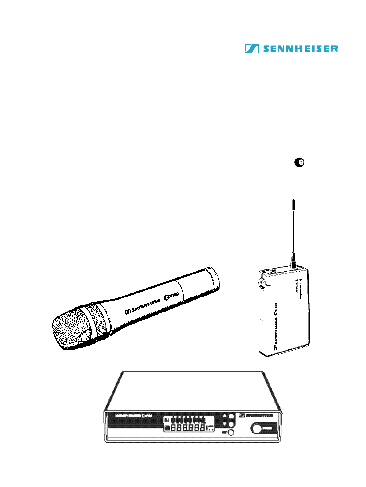
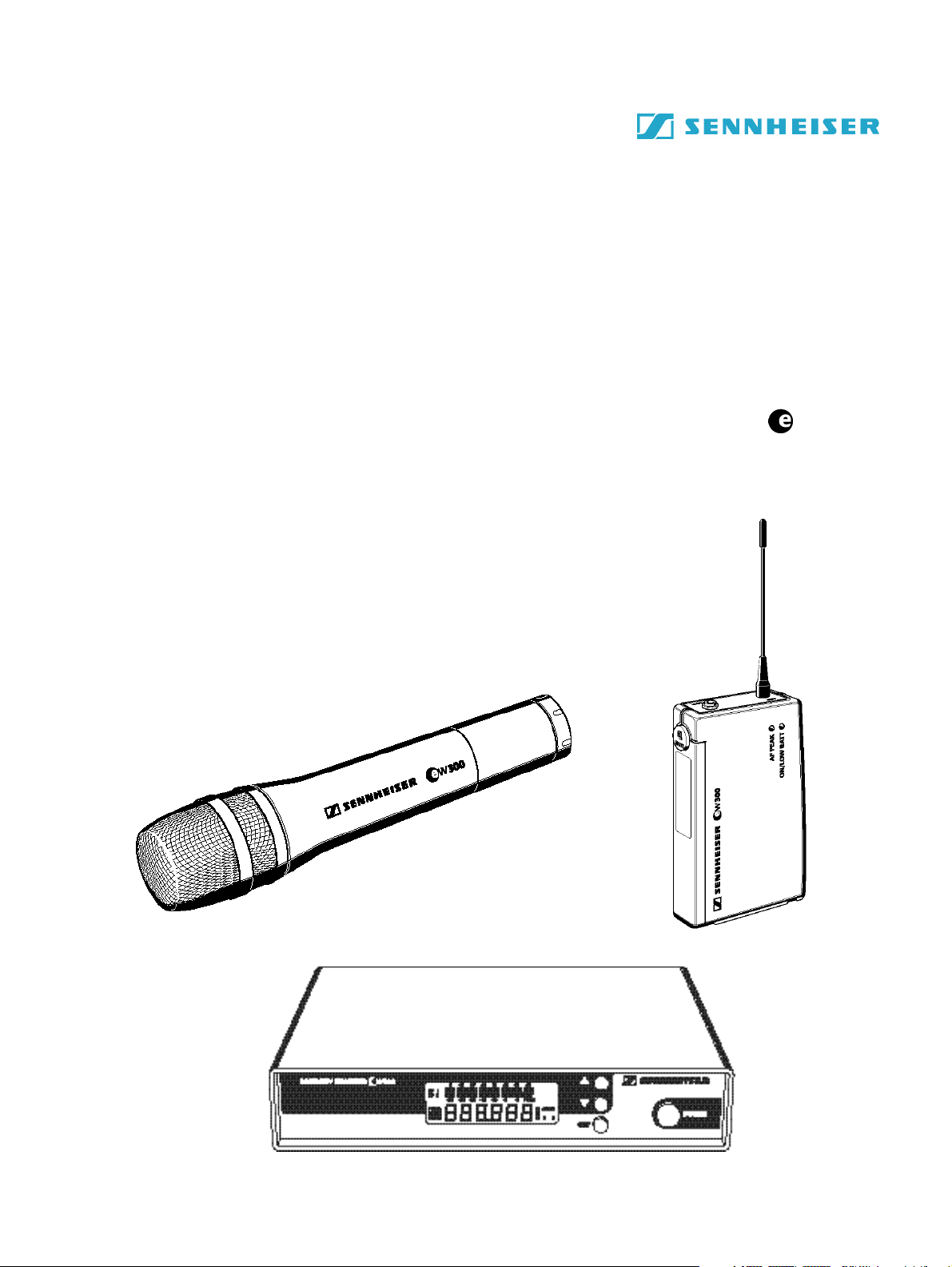
evolution wireless Serie
w 300
1
Page 2

BEDIENUNGSANLEITUNG ........................................................................................ 3
INSTRUCTION MANUAL.......................................................................................... 39
NOTICE D‘EMPLOI .................................................................................................... 75
ISTRUZIONI PER L‘USO.......................................................................................... 111
INSTRUCCIONES PARA EL USO ........................................................................... 147
GEBRUIKSAANWIJZING ....................................................................................... 183
2
Page 3
BEDIENUNGSANLEITUNG
evolution wireless Serie
w 300
3
Page 4

1 Inhalt
Kap. Inhalt Seite
1 Inhalt ................................................................................................... 4
2 Verwendungszweck ............................................................................ 5
3 Sicherheitshinweise............................................................................. 5
4 Einsatzbereiche und Inhalt der Sets .................................................. 6
5 Inbetriebnahme .................................................................................. 8
Empfänger EM 300 ...................................................................... 8
Taschensender SK 300 ............................................................... 11
Funkmikrofon SKM 300 ............................................................ 14
6 Bedienung der Sender und Empfänger ........................................... 17
7 Störungssuche ................................................................................... 27
8 Pflege und Wartung ......................................................................... 29
9 Übersicht .......................................................................................... 30
Wireless – drahtlose Übertragungsanlagen .............................. 30
Rauschunterdrückung durch HDX ............................................. 31
Steckerbelegung .......................................................................... 31
Diversity-Empfang ...................................................................... 32
Technische Daten........................................................................ 33
Zubehör ....................................................................................... 36
Sie haben die richtige Wahl getroffen!
Diese Sennheiser-Produkte werden Sie lange Jahre durch Zuverlässigkeit,
Wirtschaftlichkeit und einfache Bedienung überzeugen. Dafür garantiert
Sennheiser mit seinem guten Namen und seiner in mehr als 50 Jahren erworbenen Kompetenz als Hersteller hochwertiger elektroakustischer Produkte.
Nehmen Sie sich nun ein paar Minuten Zeit, um diese Anleitung zu lesen.
Wir möchten, daß Sie einfach und schnell in den Genuß dieser Technik
kommen.
4
Page 5

2 Verwendungszweck
Mit der evolution wireless Serie ew 300 bietet Sennheiser Musikern, VideoAmateuren, Ton-Amateuren, Reportern und lokalen Rundfunksendern moderne und technisch ausgereifte Hochfrequenz-Übertragungsanlagen mit
hoher Betriebssicherheit, einfacher und komfortabler Bedienung. Die jeweiligen Sender und Empfänger bieten drahtlose Übertragung in Studioqualität.
Der Einsatz optimierter PLL- und Mikroprozessortechnik, das Rauschunterdrückungsverfahren HDX und die True-Diversity-Technik garantieren
eine störungsfreie Übertragung.
Für die Übertragung stehen im UHF-Band fünf Frequenzbereiche mit je
1280 Sende-/Empfangsfrequenzen zur Verfügung. (Anzahl der Frequenzbereiche kann länderspezifisch eingeschränkt sein.)
Bereich A: 518 bis 550 MHz,
Bereich B: 630 bis 662 MHz,
Bereich C: 740 bis 772 MHz,
Bereich D: 790 bis 822 MHz,
Bereich E: 838 bis 870 MHz.
Auf jedem der 8 Kanäle der Sender und Empfänger können Sie eine Sendebzw. Empfangsfrequenz, die Sie aus dem voreingestellten Frequenzbereich
auswählen können, abspeichern.
In jedem Set sind die 8 Kanäle voreingestellt.
Dadurch wird
– zum einen die Anlage schnell und einfach in Betrieb genommen,
– zum anderen stören sich mehrere Anlagen nicht gegenseitig („interferenz-
frei“), wenn sie auf den vorgeschlagenen Sende-/Empfangsfrequenzen arbeiten. Alle Frequenzeinstellungen können Sie individuell ändern.
Jedes Set besteht aus:
– einem stationären Empfänger,
– einem Funkmikrofon oder Taschensender,
– passendem Zubehör.
3 Sicherheitshinweise
Öffnen Sie nicht eigenmächtig ein Gerät. Arbeiten an stromführenden Teilen
müssen immer vom Fachmann ausgeführt werden. Für Geräte, die eigenmächtig vom Kunden geöffnet wurden, erlischt die Gewährleistung.
Trennen Sie immer die Verbindung zum Stromnetz, wenn Sie Leitungen
umstecken oder das Gerät an einen anderen Platz stellen wollen.
Halten Sie Abstand zu Heizungen und Heizstrahlern, stellen Sie das Gerät
nie direkt in die Sonne.
Benutzen Sie diese Anlage nur in trockenen Räumen.
Zur Reinigung genügt es völlig, hin und wieder das Gerät mit einem leicht
feuchten Tuch abzuwischen. Verwenden Sie bitte auf keinen Fall Löse- oder
Reinigungsmittel.
5
Page 6
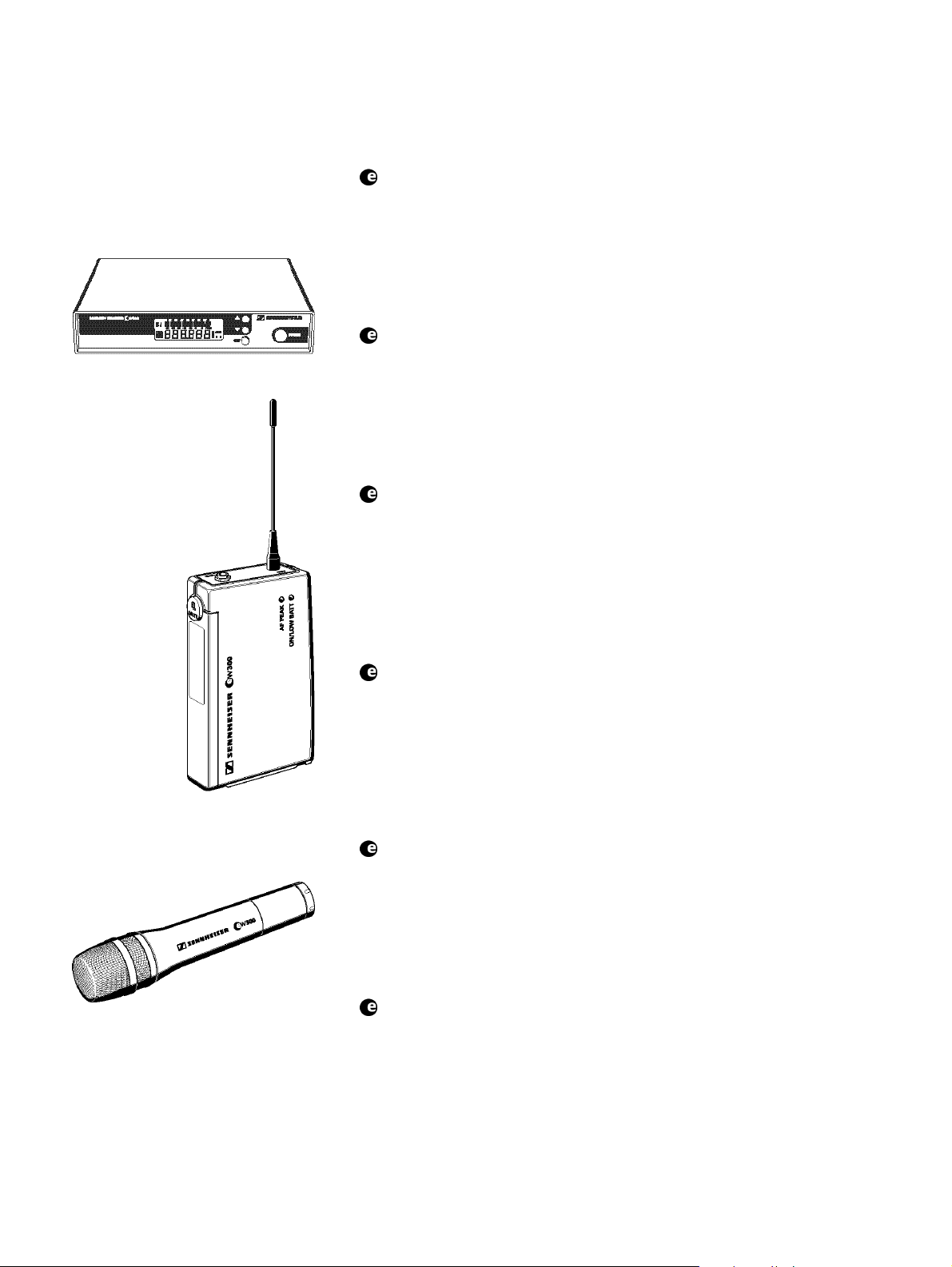
4 Einsatzbereiche und Inhalt der Sets
Set w 312
Dieses Set setzen Sie im Theater und zur Moderation ein. Das Mikrofon
kann nahezu unsichtbar getragen werden. Der Empfänger arbeitet stationär.
Das Set besteht aus dem stationären Empfänger EM 300 und dem Taschensender SK 300 mit Ansteckmikrofon ME 2 (Charakteristik: Kugel; Kondensator) sowie Netzteil, Batterie, Antennen und Bedienungsanleitung.
Set w 322
EM 300
SK 300
Dieses Set setzen Sie im Theater und zur Beschallung ein. Das Mikrofon
kann nahezu unsichtbar getragen werden. Der Empfänger arbeitet stationär.
Das Set besteht aus dem stationären Empfänger EM 300 und dem Taschensender SK 300 mit Ansteckmikrofon ME 4 (Charakteristik: Niere; Kondensator) sowie Netzteil, Batterie, Antennen und Bedienungsanleitung.
Set w 335
Dieses Set können sie unkompliziert zur Übertragung von Gesang einsetzen. Der Empfänger arbeitet stationär.
Das Set besteht aus dem stationären Empfänger EM 300 und dem Funkmikrofon SKM 300 mit Mikrofonmodul MD 835 (Charakteristik: Niere;
dynamisch) sowie Netzteil, Batterie, Antennen, Mikrofonklammer und Bedienungsanleitung.
Set w 345
Mit diesem Set können Sie Gesang rückkopplungsarm und durchsetzungsstark übertragen. Der Empfänger arbeitet stationär.
Das Set besteht aus dem stationären Empfänger EM 300 und dem Funkmikrofon SKM 300 mit Mikrofonmodul MD 845 (Charakteristik: Superniere; dynamisch) sowie Netzteil, Batterie, Antennen, Mikrofonklammer und
Bedienungsanleitung.
SKM 300
6
Set w 352
Mit diesem feedbacksicheren Headset bekommen Sie große Bewegungsfreiheit bei Gesang und Sport (z.B Aerobic). Der Empfänger arbeitet stationär.
Das Set besteht aus dem stationären Empfänger EM 300 und dem Taschensender SK 300 mit Headset (Mikrofon ME 3, Charakteristik: Superniere;
Kondensator) sowie Netzteil, Batterie, Antennen und Bedienungsanleitung.
Set w 365
Dieses rückkopplungsarme Funkmikrofon mit brillantem Sound können Sie
für Gesang und Moderation einsetzen. Der Empfänger arbeitet stationär.
Das Set besteht aus dem stationären Empfänger EM 300 und dem Funkmikrofon SKM 300 mit Mikrofonmodul ME 865 (Charakteristik: Superniere; Kondensator) sowie Netzteil, Batterie, Antennen, Mikrofonklammer
und Bedienungsanleitung.
Page 7
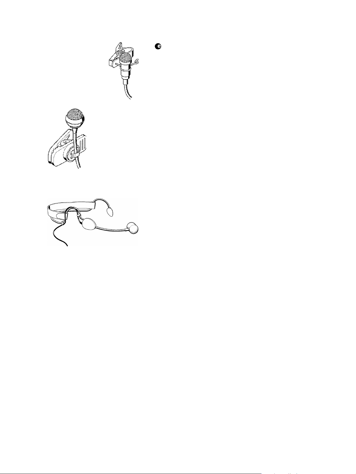
Ansteckmikrofon ME 2
mit Ansteckklammer
Ansteckmikrofon ME 4
mit Ansteckklammer
Set w 372
Musikinstrumente mit 6,3-mm-Klinkenbuchse (z.B. Gitarre) können Sie mit
diesem Set drahtlos betreiben. Der Empfänger arbeitet stationär.
Das Set besteht aus dem stationären Empfänger EM 300 und dem Taschensender SK 300 mit Instrumentenkabel sowie Netzteil, Batterie, Antennen
und Bedienungsanleitung.
Headset ME 3
7
Page 8
5 Inbetriebnahme
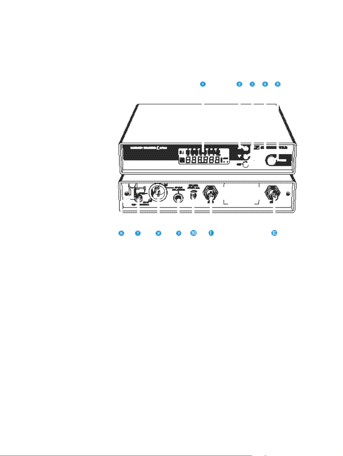
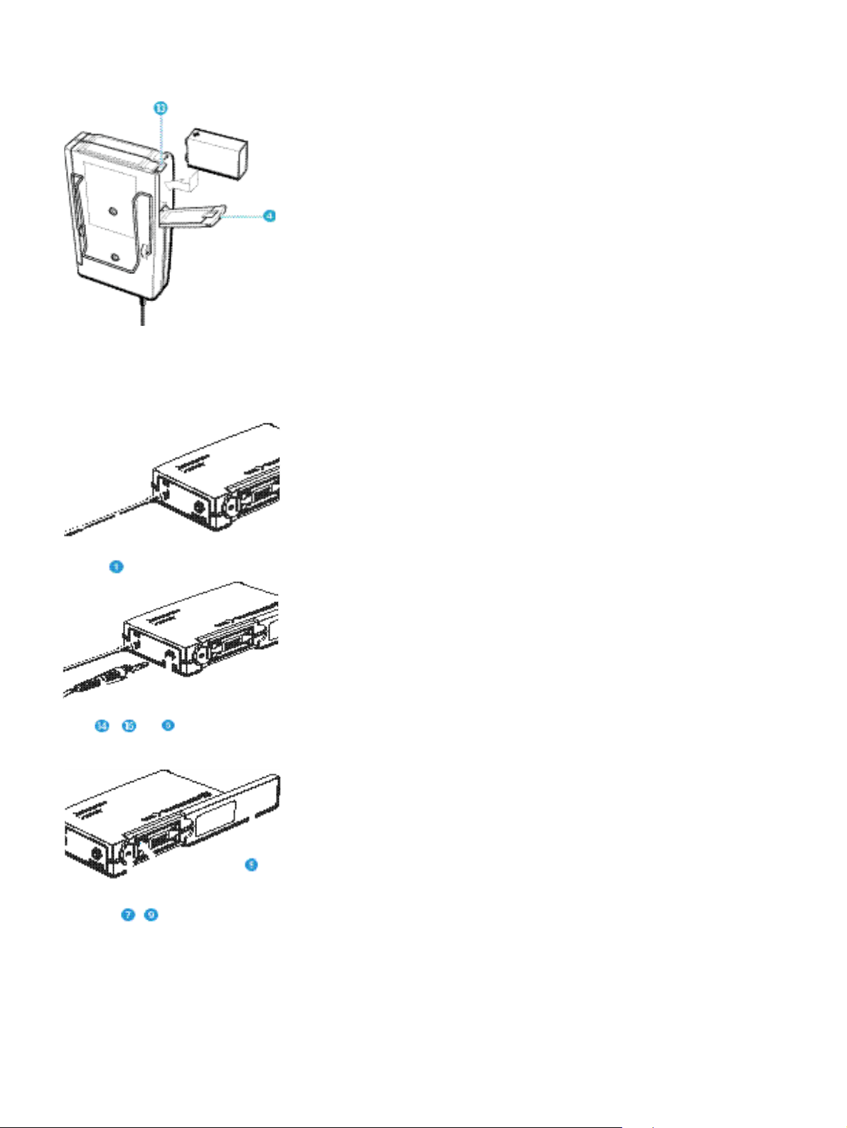
Empfänger EM 300 in Betrieb nehmen
! LC-Display
" Taste ! (UP)
# Taste " (DOWN)
$ Taste SET
% Taste POWER
& Zugentlastung für Anschlußkabel des Netzteils
' Hohl-Klinkenbuchse für Anschluß des Netzteils (DC-IN)
( XLR-3-Einbaustecker für NF-Ausgang (AF OUT BAL/UNBAL)
) 6,3-mm-Klinkenbuchse für NF-Ausgang
(AF OUT BAL/UNBAL)
* Steller für Ausgangspegel (AF LEVEL)
+ BNC-Buchse, Antenneneingang II (ANT II)
, BNC-Buchse, Antenneneingang I (ANT I)
8
Page 9
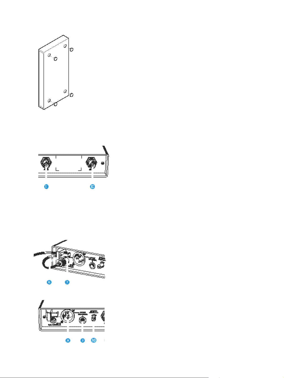
Gummifüße montieren
Damit das Gerät rutschfest auf einer Unterlage steht, liegen vier selbstklebende Gerätefüße aus Weichgummi bei.
! Säubern Sie vor der Montage der Gerätefüße die Mulden an der
Geräteunterseite, sie müssen fettfrei sein.
! Kleben Sie die Gerätefüße in die Mulden ein.
Vorsicht!
Möbeloberflächen sind mit Lacken, Polituren oder Kunststoffen behandelt, die bei Kontakt mit anderen Kunststoffen Flecken hervorrufen können. Wir können Ihnen daher trotz sorgfältiger Prüfung der
von uns eingesetzten Kunststoffe nicht garantieren, daß Verfärbungen auszuschließen sind.
Antennen anschließen
Der Empfänger EM 300 kann sowohl mit den mitgelieferten Teleskopantennen als auch mit abgesetzten Antennen (nicht im Set enthalten) verwendet werden.
Die mitgelieferten Teleskopantennen sind schnell und einfach montiert und
eignen sich für alle Anwendungen, bei denen unter guten Empfangsbedingungen eine drahtlose Übertragungsanlage ohne großen Installationsaufwand in Betrieb genommen werden soll.
! Teleskopantennen an den BNC-Buchsen + und , an der Geräte-
rückseite einstecken, ausziehen und V-förmig nach oben ausrichten.
Für den Fall, daß der Empfängerstandort nicht mit dem für einen optimalen
Empfang günstigen Antennenstandort übereinstimmt, können Sie abgesetzte
Antennen verwenden. Diese werden als Zubehör angeboten.
Netzteil anschließen
! Zur Spannungsversorgung stecken Sie den Hohlklinkenstecker vom
Netzteil in die Buchse - an der Geräterückseite des Empfängers.
! Führen Sie das Kabel durch die Zugentlastung ..
Verstärker/Mischpult anschließen
! Schließen Sie den Verstärker/das Mischpult
– am XLR-3-Ausgang / oder
– an der 6,3-mm-Klinkenbuchse 0 an.
Symmetrische und unsymmetrische Steckerbelegung siehe Kapitel
„9 Übersicht“.
9
Page 10
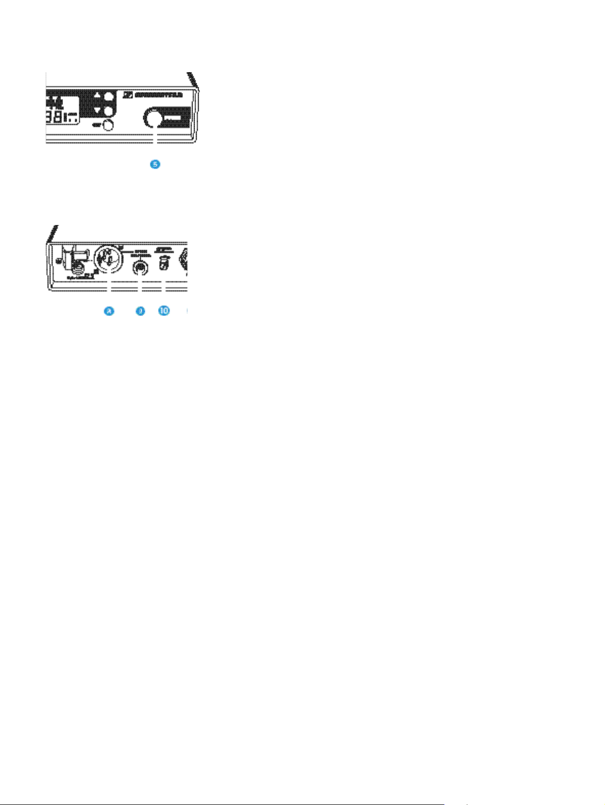
Empfänger ein/-ausschalten
! Drücken Sie die Taste POWER 1, um den Empfänger einzuschalten.
! Um den Empfänger auszuschalten, müssen Sie die Taste POWER er-
neut drücken bis der Schriftzug „OFF“ erscheint. Sie können dann die
Taste loslassen.
Nach einer Stromunterbrechung nimmt das Gerät den zuletzt gewählten
Zustand (ON/OFF) wieder an.
Ausgangspegel einstellen
! Drehen Sie den Steller für den Ausgangspegel * zur optimalen An-
passung an den Verstärker/Mischpulteingang.
10
Page 11
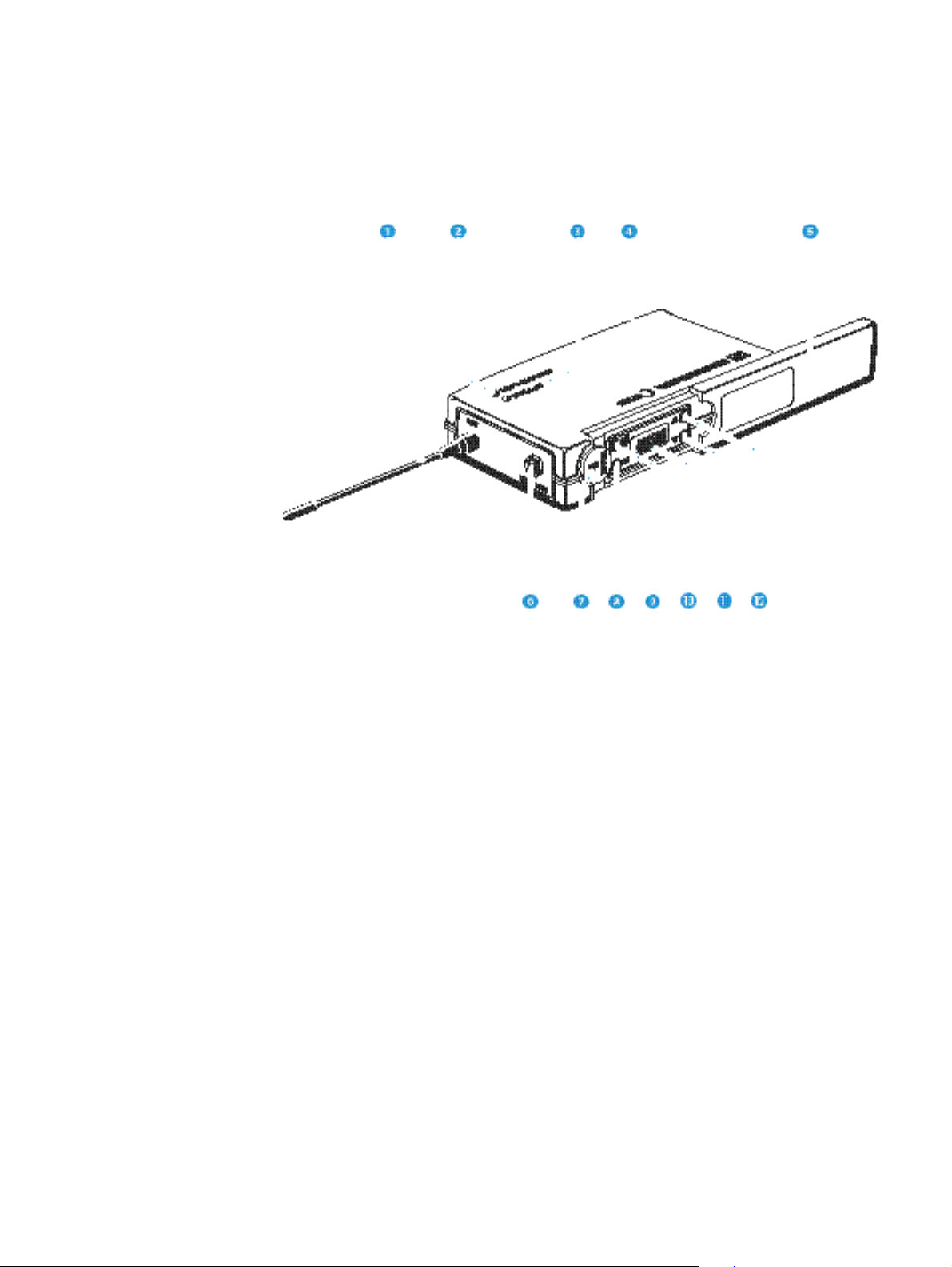
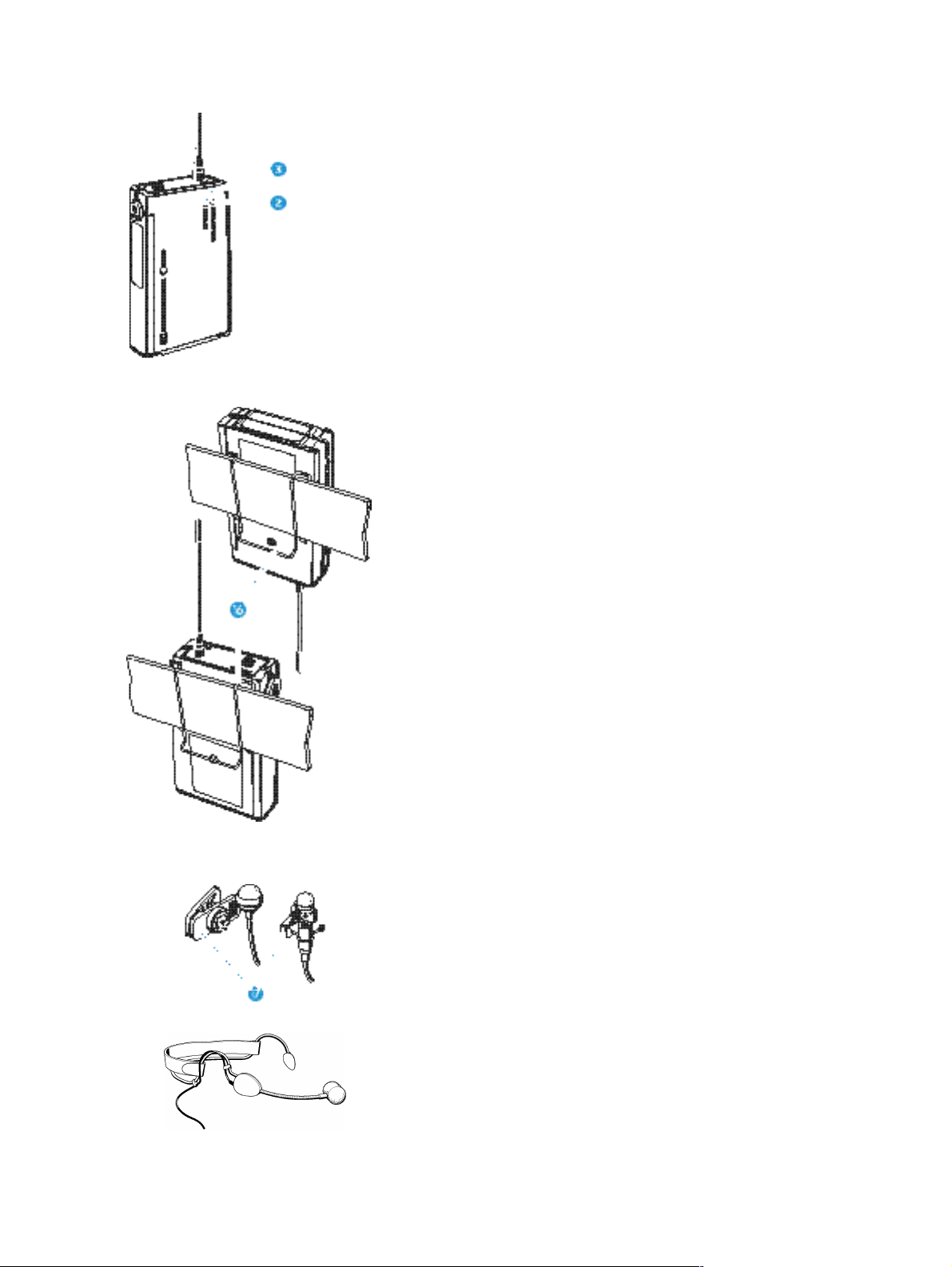
Taschensender SK 300 in Betrieb nehmen
2 Antenne
3 Betriebs- und Batteriezustandsanzeige, rote LED (ON/LOW BAT)
4 Audio-Peak-Anzeige, gelbe LED (AF-PEAK)
5 Abdeckung des Batteriefaches
1 Abdeckung für Display und Bedienelemente
. Mikrofon- und Instrumenteneingang (MIC/LINE),
3,5-mm-Klinkenbuchse
- Schalter MUTE
/ Taste SET
0 Taste ON/OFF
* Display
+ Taste " (DOWN)
, Taste ! (UP)
11
Page 12
Batterie einsetzen und wechseln
! Schieben Sie die Abdeckung des Batteriefaches 5 in Richtung des
aufgeprägten Pfeiles bis es hörbar rastet.
! Klappen Sie die Abdeckung auf.
! Schieben Sie die Blockbatterie (Typ 6 LR 61, 9 Volt) ein. Achten Sie
auf die Polarität.
! Schließen Sie das Batteriefach.
! Um die Batterie zu entnehmen, müssen Sie den roten Hebel 6 in
Richtung Geräteunterseite drücken.
Hinweis:
Der Betrieb mit Akkus ist nur eingeschränkt möglich, da mit den
geringeren Kapazitäten von Akkus nur kurze Betriebszeiten erreicht
werden können.
Antenne einschrauben
! Schrauben Sie die Antenne 2 in die Antennenbuchse (M3-Anschluß).
Mikrofonkabel/Line-Kabel einstecken
Der Mikrofoneingang stellt die Elektretspeisung zur Verfügung.
! Stecken Sie den 3,5-mm-Klinkenstecker 7 des Mikrofon- oder Line-
Kabels in die Klinkenbuchse (MIC/LINE) ..
! Verriegeln Sie den Klinkenstecker durch Einschrauben des Gewinde-
rings 8.
Sender ein-/ausschalten
! Schieben Sie die Abdeckung 1 zurück.
! Drücken Sie die Taste ON/OFF 0, um den Sender einzuschalten. Die
rote LED leuchtet dann.
! Um den Sender auszuschalten, müssen Sie die Taste ON/OFF erneut
drücken, bis im Display der Schriftzug „OFF“ erscheint. Sie können
dann die Taste loslassen. Die rote LED erlischt.
Sender stummschalten
Mit dem Schiebeschalter MUTE - können Sie den Sender stummschalten.
Der Sender bleibt in Betrieb, lediglich das Tonsignal wird abgeschaltet.
12
Page 13
Signal- und Batterieanzeige
Die gelbe Leuchtanzeige (LED) 4 an der Oberseite des Senders SK 300
zeigt Ihnen an, wenn das Tonsignal am Eingang zu hoch ist (AF-Peak).
Die rote Leuchtanzeige (LED) 3 und der Bargraph im Display informieren
Sie über den aktuellen Betriebszustand des Senders.
Bargraph:
Der Bargraph zeigt die Batterieleistung in drei Stufen an:
8 Segmente: die Batterie ist voll,
4 Segmente: die Batterieleistung ist ausreichend,
1 Segment: die Batterieleistung ist erschöpft,
sie reicht nur noch für kurze Zeit.
Hinweis:
Auch bei einer bereits benutzten Batterie können für kurze Zeit alle
8 Segmente angezeigt werden.
LED leuchtet:
Der Sender ist eingeschaltet, die Batterieleistung ist ausreichend.
LED beginnt zu blinken:
Die Leistung reicht nur noch für kurze Zeit! Die Batterie muß in
Kürze ausgewechselt werden, sie hat jetzt noch für wenige Minuten
Leistungsreserve!
Befestigung an der Kleidung
Mit dem Ansteckclip 9 läßt sich der Sender SK 300 z.B. am Gürtel einhängen.
Sie können den Sender auch so an der Kleidung befestigen, daß die Antenne
nach unten zeigt. Dazu nehmen Sie den Ansteckclip heraus und setzen ihn
um 180° gedreht wieder ein.
Befestigung der Mikrofone
Mit den Ansteckklammern : lassen sich die Ansteckmikrofone ME 2 oder
ME 4 an der Kleidung, z.B. am Jackenrevers befestigen.
Das Headset ME 3 wird so am Kopf angelegt, daß es bequem und sicher
sitzt.
Ausrichtung der Mikrofone
Die Mikrofone ME 3 und ME 4 sind Richtmikrofone und müssen so ausgerichtet werden, daß die Einsprache in Richtung der Tonquelle (z.B. Mund)
zeigt. Das ME 2 dagegen hat eine kugelförmige Charakteristik und braucht
nicht genau ausgerichtet zu werden.
13
Page 14
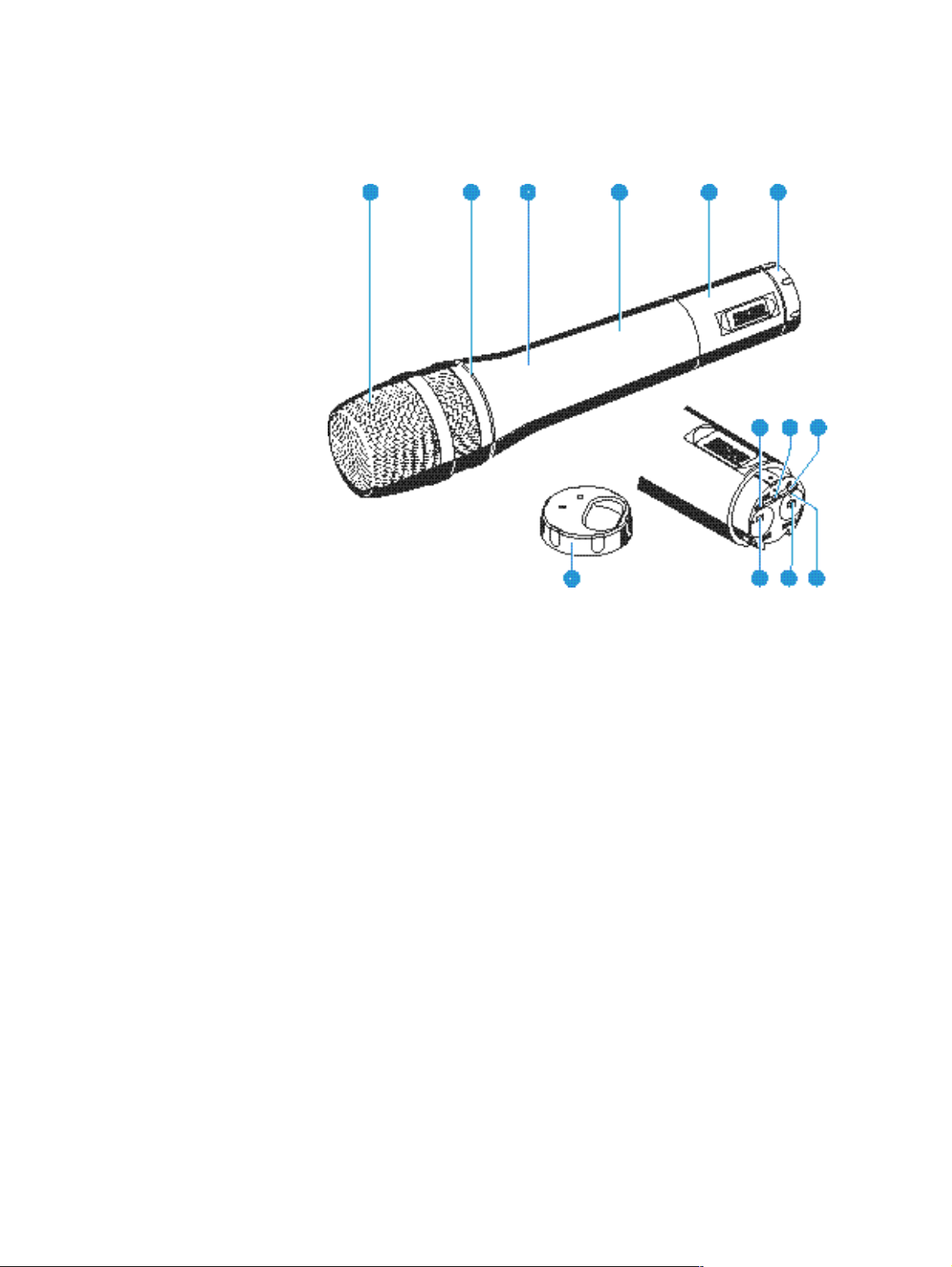
Funkmikrofon SKM 300 in Betrieb nehmen
2 Einsprachekorb
3 Farbiger Ring zur Kennzeichnung des eingebauten Mikrofonmoduls
grün: Mikrofonmodul MD 835
(Charakteristik: Niere; dynamisch)
blau: Mikrofonmodul MD 845
(Charakteristik: Superniere; dynamisch)
rot: Mikrofonmodul ME 865
(Charakteristik: Superniere; Kondensator)
4 Griff des Funkmikrofons
5 Batteriefach (von außen nicht sichtbar)
1 Displayeinheit
. Drehbare Kappe zum Schutz der Bedienelemente;
durch Drehen der Kappe . erreichbare Tasten und Anzeigen:
- Taste SET
/ Taste " (DOWN)
0 Taste ! (UP)
* Schalter MUTE
+ Taste ON/OFF
, Betriebs- und Batteriezustandsanzeige, rote LED
14
Page 15
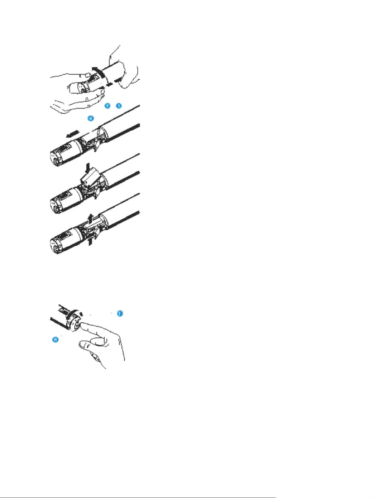
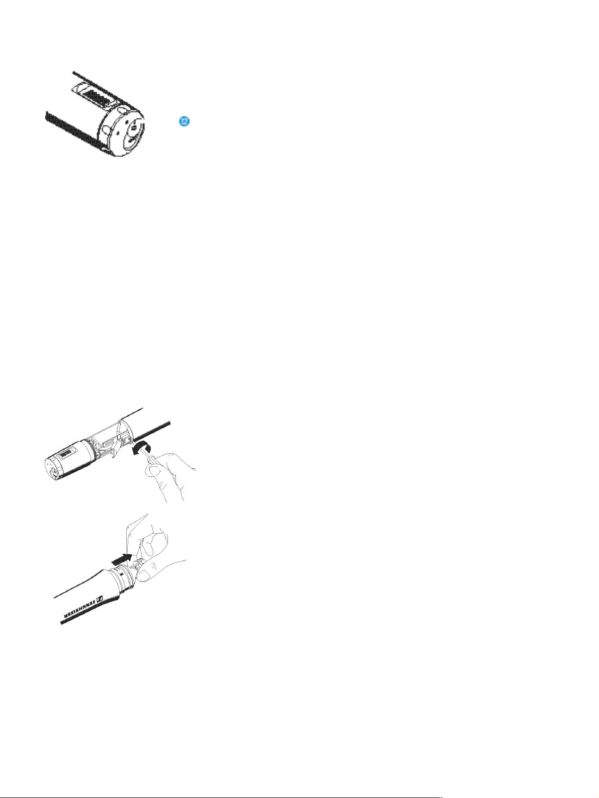
Batterie einsetzen/wechseln
! Schrauben Sie die Displayeinheit 1 vom Griff des Funkmikrofons 4
auf (gegen den Uhrzeigersinn drehen).
! Ziehen Sie die Displayeinheit 1 soweit heraus, bis das Batteriefach 5
vollständig offen ist.
! Legen Sie die Blockbatterie (Typ 6 LR 61, 9 Volt) ein. Achten Sie auf die
Polarität.
! Schieben Sie das Batteriefach in den Griff des Funkmikrofons ein.
! Schrauben Sie die Displayeinheit wieder zu.
! Um die Batterie zu wechseln, müssen Sie die Batterie nach oben (Pfeil-
richtung) herausdrücken.
Funkmikrofon ein-/ausschalten
! Drehen Sie die Kappe . am Boden des Funkmikrofons in die Stel-
lung, in der die Taste ON/OFF zu sehen ist.
! Drücken Sie die Taste ON/OFF +, um das Funkmikrofon einzuschal-
ten. Die rote LED leuchtet.
! Um das Funkmikrofon auszuschalten, müssen Sie die Taste ON/OFF
erneut drücken. bis im Display der Schriftzug „OFF“ erscheint. Sie
können dann die Taste loslassen. Die rote LED erlischt.
Sender stummschalten
Mit dem Schiebeschalter MUTE können Sie den Sender stummschalten. Der
Sender bleibt in Betrieb, lediglich das Tonsignal wird abgeschaltet.
15
Page 16
Batterieanzeige
Die rote Leuchtanzeige (LED) , und der Bargraph im Display informieren
Sie über den aktuellen Betriebszustand des Senders.
Bargraph:
Der Bargraph zeigt die Batterieleistung in drei Stufen an:
8 Segmente: die Batterie ist voll,
4 Segmente: die Batterieleistung ist ausreichend,
1 Segment: die Batterieleistung ist erschöpft,
sie reicht nur noch für kurze Zeit.
Hinweis:
Auch bei einer bereits benutzten Batterie können für kurze Zeit alle
8 Segmente angezeigt werden.
LED leuchtet:
Der Sender ist eingeschaltet, die Batterieleistung ist ausreichend.
LED blinkt:
Die Leistung reicht nur noch für kurze Zeit! Die Batterie muß in
Kürze ausgewechselt werden, sie hat jetzt noch für wenige Minuten
Leistungsreserve!
Wechsel des Mikrofonmodules
! Entnehmen Sie zunächst die Batterie, lassen Sie bitte das Funkmikrofon
gleich geöffnet.
! Schrauben Sie den Einsprachekorb ab.
! Lösen Sie die Befestigungsschraube und legen Sie sie beiseite.
! Ziehen Sie die Kapsel - wie abgebildet - heraus. Bitte berühren Sie
dabei möglichst nicht die Kontakte!
! Stecken Sie die andere Kapsel ein, sichern Sie diese wieder durch die
Befestigungsschraube und schrauben Sie den passenden Einsprachekorb auf.
! Setzen Sie die Batterie wieder ein, schließen Sie das Gehäuse und
nehmen Sie das Mikrofon wieder in Betrieb.
Hinweis:
Kapsel und Einsprachekorb mit Schaumeinsatz bilden eine akustische Einheit und müssen stets gemeinsam gewechselt werden. Zur
einfacheren Unterscheidung sind die Mikrofonmodule farbig gekennzeichnet (grün: MD 835. blau: MD 845, rot: ME 865).
16
Page 17

ON/OFF
POWER
6 Bedienung der Sender und Empfänger
Der schnelle Einstieg
Die Sender und Empfänger der Sennheiser evolution wireless Serie ew 300
sind werkseitig so voreingestellt, daß Sie nach der Inbetriebnahme der Geräte
(# „5 Inbetriebnahme“) sofort arbeiten können. Beachten Sie jedoch, daß
die Aussteuerung des Senders vom Einsatzzweck abhängig ist. Um Übersteuerungen und damit Verzerrungen zu vermeiden, sollten Sie in jedem Fall
überprüfen, ob die voreingestellte Aussteuerung für Ihren Einsatzzweck richtig
ist (# „Aussteuerung einstellen“).
Tasten
Mit der Taste ON/OFF bzw. beim Empfänger EM 300 mit der Taste POWER
schalten Sie den Sender bzw. Empfänger ein oder aus.
MUTE
SET
Mit dem Schalter MUTE (nur Sender) unterbrechen Sie das Audio-Signal
geräuschfrei.
Mit der Taste SET
– rufen Sie das Menü zur Eingabe der Werte auf,
– schalten Sie von einem Menüpunkt zum nächsten weiter,
– schalten Sie bei Eingabe eines Namens zum nächsten Segment weiter,
– kehren Sie an den Menüanfang zurück.
!
Mit der Taste UP
– ändern Sie den Wert eines Menüpunktes,
– ändern Sie bei der Eingabe eines Namens ein einzelnes Zeichen.
"
Mit der Taste DOWN
– ändern Sie den Wert eines Menüpunktes,
– ändern Sie bei der Eingabe eines Namens ein einzelnes Zeichen.
17
Page 18
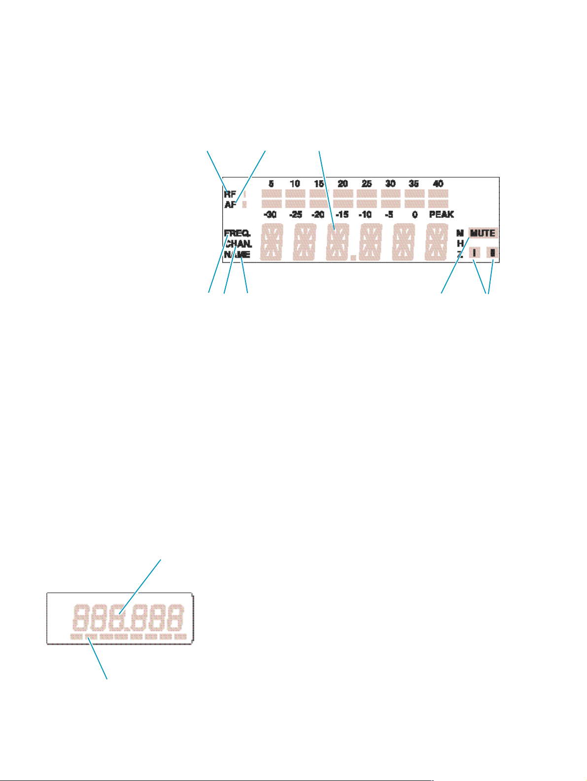
Anzeigen im LC-Display
Empfänger EM 300
2 3 4
5 1 . - /
2 Achtstufige Anzeige des ankommenden HF-Signals
3 Achtstufige Anzeige des ankommenden NF-Signals mit Über-
steuerungsanzeige „PEAK“
4 Alphanumerische Hauptanzeige
$ Anzeige des Menüpunkts „Frequency“. (Sie kann Standardanzeige des
Empfängers am Menüanfang sein und erscheint nach dem Einschalten.)
% Anzeige der Kanalnummer „Channel“. (Sie kann Standardanzeige des
Empfängers am Menüanfang sein und erscheint nach dem Einschalten.)
& Anzeige des Menüpunkts „Name“. (Sie kann Standardanzeige des Em-
pfängers am Menüanfang sein und erscheint nach dem Einschalten.)
' Squelchanzeige „MUTE“ (Rauschsperren aktiv)
( Diversity-Anzeige (Antenne I oder Antenne II aktiv)
(# „11 Diversity-Empfang“)
2
3
18
Sender SK 300 und SKM 300
2 Alphanumerische Hauptanzeige
" Dreistufige Batterieanzeige
Hinweis:
Werden Einstellungen im Bedienmenü beschrieben, die für alle Geräte gleich
sind, wird nur die Hauptanzeige des EM 300 abgebildet.
Page 19

Grundfunktionen des Sennheiser-Bedienmenüs
Ein besonderes Merkmal der Sennheiser evolution wireless Serie ew 300 ist
die gleichartige Bedienung von Sendern und Empfängern. Unter Streß, wie
auf der Bühne und in laufenden Sendungen, kommt es darauf an, schnell
und präzise in den Betrieb eingreifen zu können. Die Bedienung muß „blind“
und an jedem Gerät mit gleichen Bedienfolgen geschehen können. Dies ist
mit den gleichen Tasten (SET,
als auch am Empfänger möglich.
Wichtig:
Durch Betätigung der Tasten !/" können Sie unmittelbar zwischen den voreingestellten Kanälen (Presets) umschalten. Die Anzeige blinkt. Die Änderung wird sofort wirksam.
2 Mit der Taste SET gelangen Sie in das Bedienmenü:
Mit einem kurzen Druck wählen Sie den nächsten Menüpunkt an.
Im Display wird der angewählte Menüpunkt und anschließend der
aktuelle Wert des Menüpunktes angezeigt.
3 Mit den Tasten " und ! werden die Einstellungen im jeweiligen
Menüpunkt vorgenommen:
Die geänderte Einstellung blinkt im Display. Wenn Sie den ursprünglichen Wert wieder einstellen, hört das Blinken auf.
", !) und je einem Display sowohl am Sender
Wichtig:
Ihre Eingaben werden ohne weitere Bestätigung wirksam und
sind sofort gespeichert!
In den Menüpunkten „TUNE“ und „NAME“ sind die Tasten ! und "
mit einem Schnell-Lauf („Repetieren“) ausgestattet. Drücken Sie die
Taste kurz, wechselt die Anzeige zum nächsten bzw. vorherigen Wert.
Wenn Sie die Taste drücken und gedrückt halten, beschleunigt sich
die Anzeige. Lassen Sie die Taste wieder los und starten neu, beginnt
der Durchlauf der Anzeige wiederum langsam. Sie gelangen so in
beiden Anzeigerichtungen schnell und komfortabel zum gewünschten Einstellwert.
4 Mit der Taste SET gelangen Sie zum Menüanfang zurück:
Drücken Sie die Taste SET, um nach Abschluß der Eingabe zum Menüanfang zurückzukehren. Im Display erscheint wieder die Standardanzeige.
19
Page 20

Übersicht über die Menüpunkte
Die Bedienung von Sendern und Empfängern der Sennheiser evolution
wireless Serie ew 300 wird durch die weitestgehende Vereinheitlichung des
Bedienmenüs von Sendern und Empfängern vereinfacht:
Anzeige im Display Sender Empfänger
SEnSit Einstellen und Ändern der –
Aussteuerung (# Seite 21)
SQELCH – Einstellen und Ändern der RauschSqELCH sperrenschwelle (# Seite 22)
DISPL Auswahl der Standardanzeige Auswahl der Standardanzeige
DiSPL (# Seite 23) (# Seite 23)
TUNE Eingeben und Ändern der Eingeben und Ändern der
tune Sendefrequenz (# Seite 24) Empfangsfrequenz (# Seite 24)
NAME – Eingeben und Ändern eines Na-
mens beim Empfänger EM 300
(# Seite 25)
LOCK Sperren der Bedienelemente gegen Sperren der Bedienelemente gegen
Loc unbeabsichtigtes Verstellen unbeabsichtigtes Verstellen
(# Seite 26) (# Seite 26)
20
Page 21
Frequenz, Kanäle auswählen
! Durch Betätigung der Tasten !/" können Sie unmittelbar zwischen
den voreingestellten Kanälen (Presets) umschalten. Die Anzeige blinkt.
Die Änderung wird sofort wirksam.
! Durch Drücken der Taste SET bestätigen Sie die Eingabe. Die Anzei-
ge blinkt nicht mehr.
Hinweis:
Sie können auswählen, welche Standardanzeige (Frequenz, Kanalnummer oder beim Empfänger EM 300 auch der Name) am Menüanfang angezeigt werden soll (# „Standardanzeige umschalten“).
Werkseitig ist die Frequenzanzeige voreingestellt.
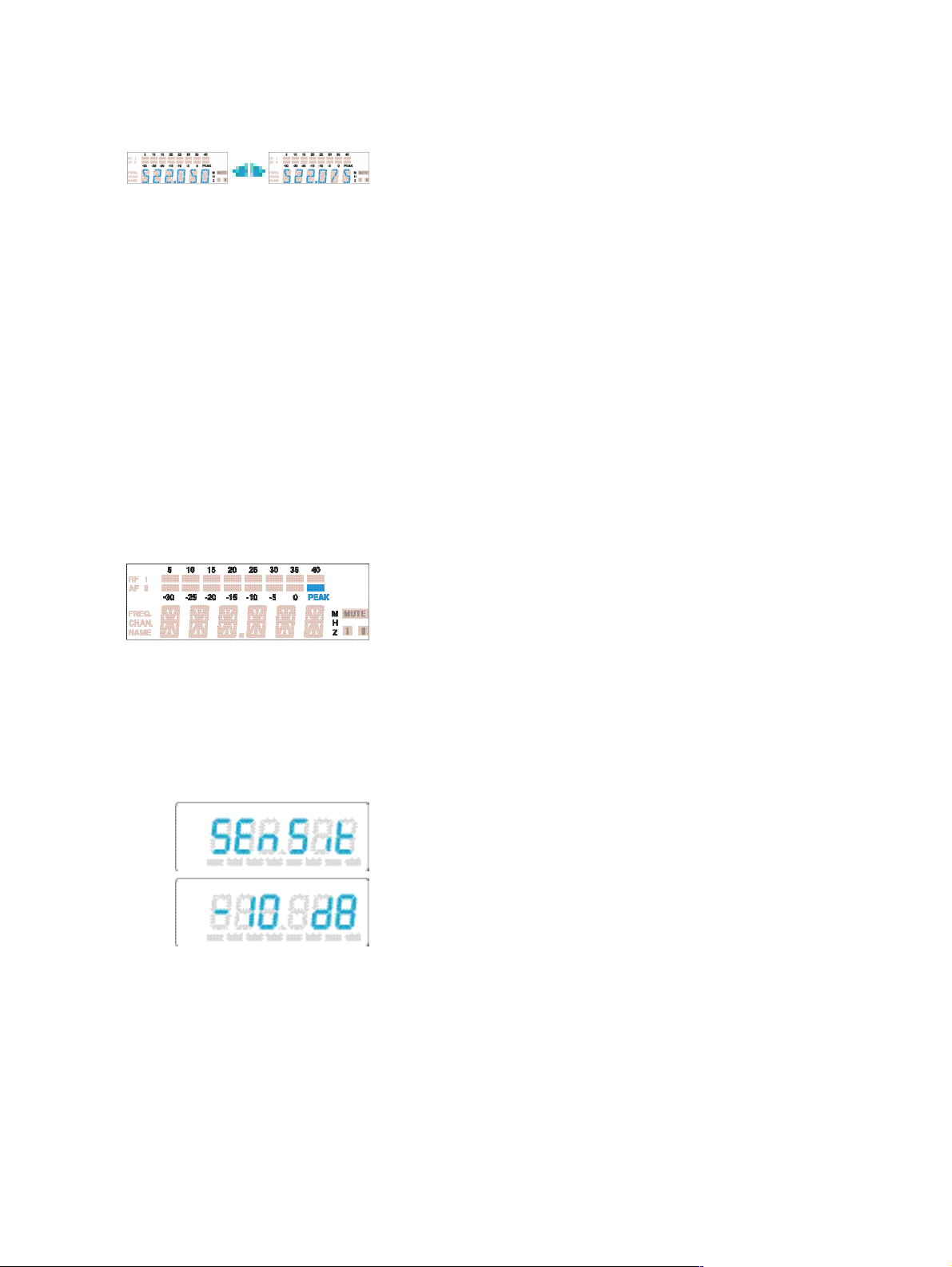
SenSit
Aussteuerung einstellen (nur Sender)
Bei Nahbesprechung, bei lauter Stimme des Sprechers oder bei lauten Musikpassagen kann es zu Übersteuerungen der Sendestrecke kommen, die sich
als Verzerrungen bemerkbar machen. Beim Empfänger EM 300 wird die
Übersteuerung durch das Aufleuchten des Segments „PEAK“ im NF-Pegel
angezeigt. Beim Sender SK 300 leuchtet die gelbe Audio-Peak-LED. Ist andererseits die Empfindlichkeit zu niedrig eingestellt, wird die Sendestrecke
zu schwach ausgesteuert. Dieses führt zu einem verrauschten Signal.
Sie müssen daher die Empfindlichkeit so einstellen, daß nur bei den lautesten
Passagen das Segment „PEAK“ im NF-Pegel des Empfängers aufleuchtet.
Für die grobe Voreinstellung können Sie von folgenden Richtwerten ausgehen:
laute Musik/Gesang: -30 / -20 dB
Moderation: -20 / -10 dB
Interview: -10 / 0 dB
! Wählen Sie mit der Taste SET den Menüpunkt „SEnSit“ an. Im Dis-
play wird der Schriftzug „SEnSit“ und anschließend der aktuelle Wert
der Eingangsempfindlichkeit angezeigt.
! Mit den Tasten !/" können Sie nun die Eingangsempfindlichkeit ver-
ändern. Sie können sie in 10-dB-Schritten zwischen 0 und -30 dB verändern. Der eingestellte Wert blinkt im Display und wird sofort übernommen.
! Drücken Sie die Taste SET, um an den Menüanfang zurückzukehren.
Im Display erscheint wieder die Standardanzeige.
21
Page 22

SQELCH
SqELCH
Rauschsperrenschwelle einstellen (nur Empfänger)
Der Empfänger der Sennheiser evolution wireless Serie ew 300 ist mit einer
einstellbaren Rauschsperrenschwelle ausgestattet, die lästiges Rauschen bei
ausgeschaltetem Sender unterbindet. Darüber hinaus verhindert sie das Aufrauschen, wenn der Sender den Empfangsbereich verläßt und daher am
Empfänger keine ausreichende Sendeleistung mehr zur Verfügung steht.
! Um die Rauschsperrenschwelle einzustellen, müssen Sie mit der Ta-
ste SET den Menüpunkt „SQELCH“ anwählen. Im Display wird der
Schriftzug „SQELCH“ und anschließend die aktuelle Einstellung der
Rauschsperrenschwelle angezeigt.
! Mit den Tasten !/" können Sie nun die Rauschsperrenschwelle ein-
stellen. Sie können die Rauschsperrenschwelle ausschalten (0 dB) oder
in 5-dB-Schritten einen Wert zwischen 5 dB und 40 dB einstellen. Ein
kleinerer Wert senkt die Rauschsperrenschwelle, ein größerer erhöht
sie. Im Display blinkt der eingestellte Wert. Setzen Sie die Rauschsperrenschwelle bei ausgeschaltetem Sender auf den niedrigsten Wert,
ohne daß der Empfänger aufrauscht. Ein zu hoher Wert vermindert
die Reichweite der Sendestrecke.
Hinweis:
Ist die Rauschsperrenschwelle ausgeschaltet (0 dB), und kein passender Sender in Betrieb, tritt dauerhaft lautes Rauschen auf. Dies wird
beim Empfänger EM 300 durch Aufleuchten der Peak-Anzeige des
AF-Bargraphen angezeigt.
! Drücken Sie die Taste SET, um an den Menüanfang zurückzukehren.
Im Display erscheint wieder die Standardanzeige.
22
Page 23
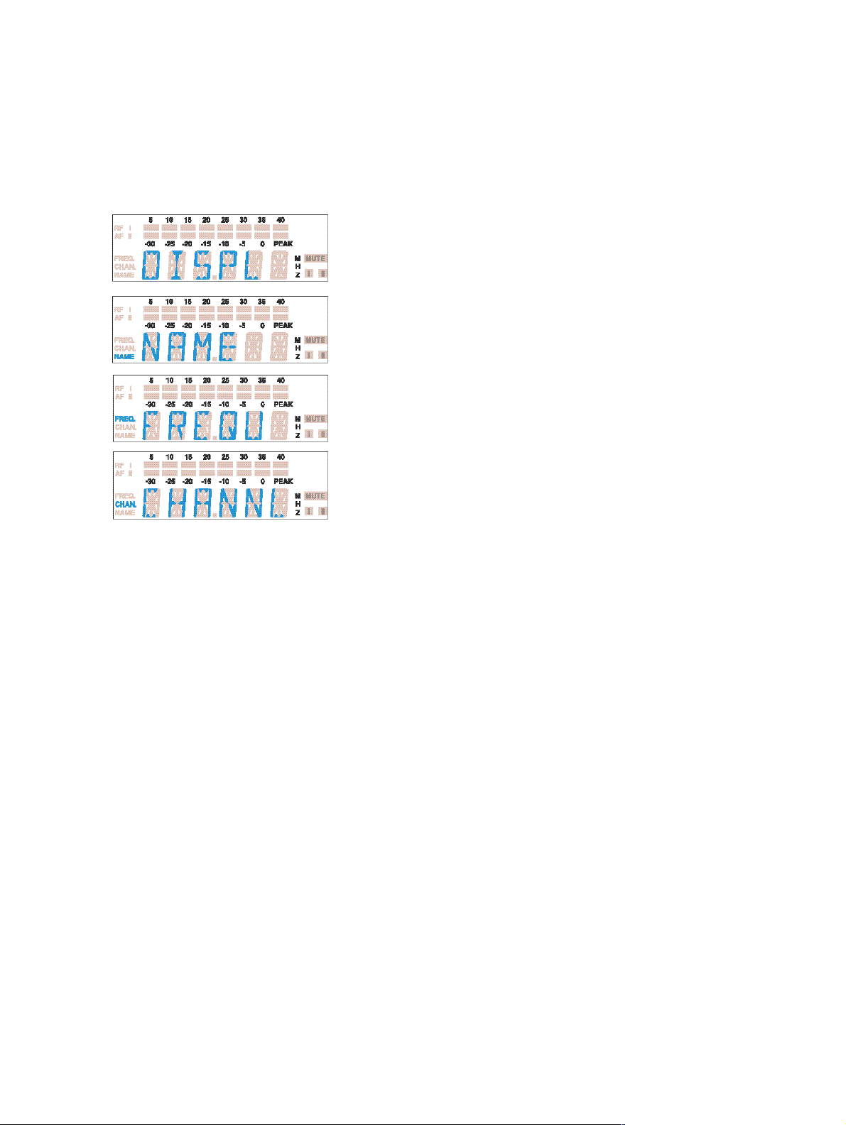
DISPL
DiSPL
Standardanzeige umschalten
Bei allen Sendern und Empfängern können Sie die Standardanzeige zwischen Frequenz und Kanalnummer umschalten. Bei dem Empfänger EM 300
können Sie die Standardanzeige zwischen Frequenz, Kanalnummer und
Namen umschalten.
! Wählen Sie mit der Taste SET den Menüpunkt „DISPL“ an. Im Dis-
play erscheint der Schriftzug „DISPL“ und anschließend die aktuelle
Einstellung.
! Mit den Tasten !/" können Sie wechseln zwischen
Name (nur EM 300): „NAME“
Frequenz: „FREQU“
Kanalnummer: „CHANNL“
Im Display blinkt die aktuelle Einstellung der Standardanzeige.
! Drücken Sie die Taste SET, um an den Menüanfang zurückzukehren.
Im Display erscheint die neue Standardanzeige.
23
Page 24

Kanäle (Presets) konfigurieren
Die Sender- und Empfänger der Sennheiser evolution wireless Serie ew 300
haben je 8 umschaltbare Kanäle (Presets). Auf jedem Kanal können Sie eine
Sende- bzw. Empfangsfrequenz abspeichern. Bei dem Empfänger EM 300
können Sie zusätzlich einen Namen vergeben.
Zwischen den Kanälen (Presets) können Sie umschalten (# „Frequenz, Kanäle auswählen“).
TUNE
tune
Frequenzen einstellen
Sie können die Sende- und Empfangsfrequenz in 25-kHz-Schritten über eine
Bandbreite von maximal 32 MHz verändern.
Hinweise speziell zum Multikanalbetrieb:
Sie können mehrere Geräte der Sennheiser evolution wireless Serie ew 300 auf
unterschiedlichen Frequenzen gleichzeitig benutzen. Die werkseitig voreingestellten Frequenzen sind so ausgewählt, daß sich die Funkstrecken nicht gegenseitig
stören. Bevor Sie neue Frequenzkombinationen eingeben, sollten Sie sich über
Randbedingungen in der Broschüre „Sennheiser Revue, Teil 3: HochfrequenzTonübertragungs-Technik mit Planungsteil HF-Technik für die Praxis“, die
Sie bei Ihrem Sennheiser-Vertriebspartner bestellen können, informieren.
! Wählen Sie den Kanal aus, für den Sie die Frequenz einstellen wollen.
! Wählen Sie mit der Taste SET den Menüpunkt „TUNE“ an. Im Dis-
play wird zunächst der Schriftzug „TUNE“ und anschließend die Frequenzeinstellung des ausgewählten Kanals angezeigt.
! Mit den Tasten !/" können Sie die Frequenz in 25-kHz-Schritten ver-
ändern. Die neue Frequenz wird im Display blinkend angezeigt und
sofort übernommen.
! Drücken Sie die Taste SET, um zum Menüanfang zurückzukehren.
Im Display erscheint wieder die Standardanzeige.
24
Page 25
NAME
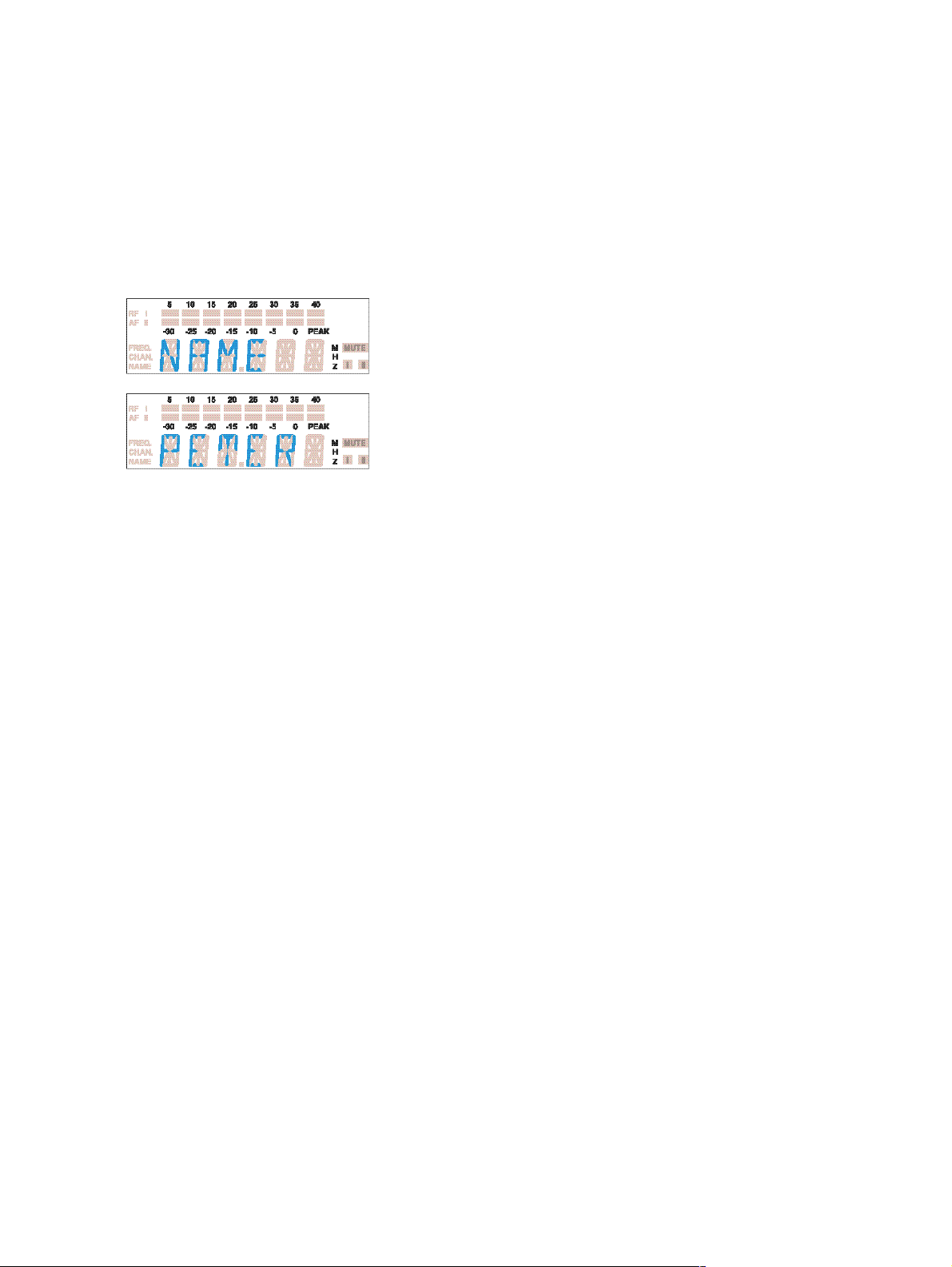
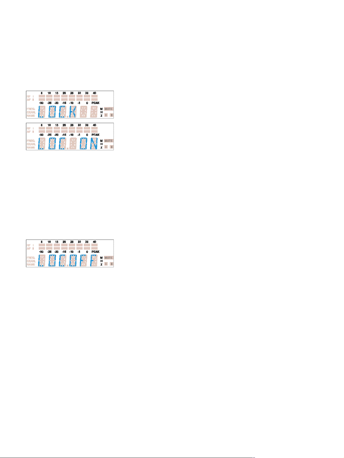
Name vergeben (nur EM 300)
Dem stationären Empfänger EM 300 können Sie einen Namen zuordnen.
Der Name kann sich aus bis zu sechs Zeichen zusammensetzen wie z.B.:
− Buchstaben mit der Ausnahme von Umlauten,
− Zahlen von 1 bis 0,
− den Sonderzeichen: () - _ und Leerzeichen.
Häufig wird der Name des Musikers verwendet.
! Wählen Sie mit der Taste SET den Menüpunkt „NAME“ an. Im Dis-
play wird der Schriftzug „NAME“ und anschließend wird der eingestellte Name angezeigt.
! Drücken Sie die Tasten !/", um die Eingabe zu aktivieren. Im Dis-
play blinkt das erste Segment.
! Mit den Tasten !/" können sie nun ein Zeichen auswählen.
! Drücken Sie Taste SET, um zum nächsten Segment zu wechseln und
wählen Sie das nächste Zeichen aus.
! Haben Sie den Namen vollständig eingegeben, müssen Sie die Taste
SET drücken, um an den Menüanfang zurückzukehren. Im Display
erscheint wieder die Standardanzeige.
25
Page 26
LOCK
Loc
Bedienung sperren
Um zu verhindern, daß während des Betriebs unbeabsichtigt Veränderungen vorgenommen werden, empfehlen wir Ihnen mit der Lock-Funktion die
Tasten zu sperren.
Sperre einschalten
! Nachdem Sie alle Eingaben beendet haben, müssen Sie mit der Taste
SET den Menüpunkt „LOCK“ anwählen. Die aktuelle Einstellung wird
angezeigt.
! Drücken Sie die Taste !, um die Eingabe zu sperren. Im Display
blinkt die Anzeige „LOC ON“.
! Drücken Sie die Taste SET, um an den Menüanfang zurückzukehren.
Hinweis:
Wenn Sie nun die Tasten !/" oder ON/OFF drücken, erscheint im
Display der Schriftzug „LOCK“ und Sie können keine Veränderungen
vornehmen.
Sperre aufheben
! Wählen Sie mit der Taste SET den Menüpunkt „LOCK“ an. Im Dis-
play erscheint die Anzeige „LOC ON“.
! Drücken Sie die Taste ", um die Lock-Funktion aufzuheben. Im Dis-
play blinkt die Anzeige „LOC OFF“.
! Drücken Sie die Taste SET, um an den Menüanfang zurückzukehren.
Im Display erscheint die Standardanzeige und die Bedienung ist nun
wieder möglich.
26
Page 27

7 Störungssuche
Fehlercheckliste
Fehler Mögliche Ursache
Keine Betriebsanzeige $ Verbrauchte Batterien
$ Kein Netzanschluß
Kein HF-Signal $ Sender und Empfänger nicht auf der
exakt gleichen Frequenz
$ Reichweite der Sendestrecke ist über-
schritten
HF-Signal vorhanden, kein $ Sender ist stummgeschaltet
Tonsignal („MUTE“)
$ Rauschsperrenschwelle am
Empfänger ist zu hoch eingestellt
Tonsignal ist verrauscht $ Aussteuerung des Senders ist zu
niedrig
$ Ausgangspegel des Empfängers ist zu
niedrig
Tonsignal ist verzerrt $ Aussteuerung des Senders ist zu
hoch
$ Ausgangspegel des Empfängers ist zu
hoch
! Rufen Sie bei Ihrem Sennheiser-Partner an, wenn Sie dennoch Probleme
beim Betrieb Ihrer Sendeanlage haben. Er hat eine Lösung für Sie parat.
27
Page 28

Empfehlungen und Tips
... für die Ansteckmikrofone ME 2 und ME 4
$ Plazieren Sie das Mikrofon mittig, um Pegelschwankungen bei einer Kopf-
drehung im Rahmen zu halten.
$ Vermeiden Sie Einwirkung von Schweiß durch direkten Hautkontakt.
$ Montieren Sie das Mikrofon sorgfältig und verlegen Sie die Leitung so,
daß keine Geräusche durch Reibung an der Kleidung entstehen.
$ Setzen Sie das Richtmikrofon ME 4 immer mit Windschutz ein und rich-
ten Sie es auf die Tonquelle (z.B. Mund) aus.
... für das Headsetmikrofon ME 3
$ Setzen Sie das Mikrofon immer mit Poppschutz ein und plazieren Sie es
am Mundwinkel.
$ Durch den Abstand zum Mund können Sie die Tiefenwiedergabe variieren.
$ Achten Sie darauf, daß die Einsprache zum Mund hin ausgerichtet ist.
Die Einsprache ist durch einen kleinen Punkt gekennzeichnet.
... für den Taschensender SK 300
$ Kreuzen Sie nicht die Antenne und die Mikrofonleitung.
$ Die Antenne sollte nicht direkt am Körper anliegen. Betreiben Sie den
Sender möglichst mit frei hängender Antenne.
$ Den optimalen Sound erreichen Sie durch richtige Aussteuerung des Sen-
ders.
... für das Funkmikrofon SKM 300
$ Halten Sie das Funkmikrofon in der Mitte des Griffes. Oben am Korb
gehalten beeinflussen Sie die Richtcharakteristik des Mikrofons, zu weit
unten am Griff vermindern Sie die abgestrahlte Sendeleistung und damit
die Reichweite des Senders.
$ Durch den Abstand zum Mund können Sie die Tiefenwiedergabe variieren.
$ Den optimalen Sound erreichen Sie durch die richtige Aussteuerung des
Senders.
28
Page 29

... für den optimalen Empfang
$ Die Reichweite des Senders ist sehr abhängig von den örtlichen Bedin-
gungen. Sie kann zwischen 10 m und 150 m betragen. Nach Möglichkeit
sollten Sie für freie Sicht zwischen Sende- und Empfangsantenne sorgen.
$ Bei ungünstigen Empfangsbedingungen sollten Sie beim EM 300 zwei
abgesetzte Antennen über Antennenkabel einsetzen (siehe SennheiserZubehörprogramm).
$ Halten Sie den empfohlenen Mindestabstand zwischen Sende- und Emp-
fangsantenne ein: 5 m. Damit vermeiden Sie eine HF-Übersteuerung des
Empfängers.
$ Halten Sie den empfohlenen Mindestabstand der Empfangsantennen zu
Stahl und Beton ein: 50 cm.
... für den Betrieb einer Multikanal-Anlage
$ Sie können nicht alle einstellbaren Frequenzkombinationen parallel ein-
setzen. Die werkseitig voreingestellten Frequenzen (Presets) sind jedoch für
Multikanalanwendung nutzbar. Zu alternativen Frequenzkombinationen
berät Sie Ihr Sennheiser-Partner.
$ Vermeiden Sie beim Einsatz mehrerer Sender Störungen in den Sende-
strecken durch ausreichenden Abstand der Sender zueinander. Die Sender sollten mindestens 20 cm Abstand voneinander haben.
$ Nutzen Sie spezielles Zubehör für Multikanal-Anwendungen (siehe
Sennheiser-Zubehörprogramm).
8 Pflege und Wartung
Funkmikrofon SKM 300
Sie sollten hin und wieder den Einsprachekorb des Funkmikrofons SKM 300
reinigen.
! Schrauben Sie den Einsprachekorb vom Funkmikrofon ab (gegen den
Uhrzeigersinn drehen).
! Reinigen Sie den Einsprachekorb mit einem leicht feuchten Tuch von
innen und von außen.
Hinweis:
Verwenden Sie auf keinen Fall Löse- oder Reinigungsmittel. Berühren Sie möglichst nicht die elektrischen Kontakte.
! Schrauben Sie den Einsprachekorb wieder auf das Funkmikrofon auf.
29
Page 30

9 Übersicht
Wireless – drahtlose Übertragungsanlagen
Freiheit auf der Bühne, kein Kabelgewirr, kein Stolpern über störende Kabel, all das wird möglich mit drahtlosen (wireless) Übertragungsanlagen.
Gefunkt wird im UHF-Bereich. Und das aus guten Gründen: Dort stören
keine Oberwellen von Netzteilen, Leuchtstofflampen oder Kühlgeräten usw.
Die Funkwellen breiten sich besser aus als im UKW oder VHF-Bereich, die
Sendeleistung kann sehr gering gehalten werden und nicht zuletzt sind einige UHF-Bereiche von der zuständigen Zulassungsbehörde weltweit für
Wireless-Anwendungen freigegeben.
Bei den Sendern gibt es zwei Typen. Es gibt Mikrofone, die direkt mit dem
Sender verbunden sind (Funkmikrofone) und es gibt Taschensender, an denen
das Mikrofon oder das Musikinstrument (z.B. Gitarre) mit einem Kabel angeschlossen werden.
Frische Batterien sorgen bei Sendern stets für gute Sendeleistung über eine
lange Betriebsdauer. Es sollten stets Alkali-Mangan-Batterien verwendet werden. Auch gilt es zu bedenken, daß Batterien eine längere Betriebsdauer
haben als Akkus.
Eine gute Einstellung des Empfindlichkeitsreglers am Sender verhindert einerseits eine Übermodulation mit starken Verzerrungen, andererseits eine
Untermodulation mit zu geringem Signal/Rauschabstand. Die Einstellung
sollte vor jedem Auftritt geprüft werden.
Die richtige Position von Ansteckmikrofonen muß ausprobiert werden. Im
Haaransatz, fest im Kostüm eingenäht oder einfach am Jackenrevers, es gibt
viele Orte dafür. Schweiß und Schminke sind die größten Feinde für die
kleinen Ansteckmikrofone.
Fehler wie z.B. Verzerrungen, Pfeifen oder starkes Rauschen können auftreten, wenn mehrere Sender auf der Bühne benutzt werden. Dann sind die
Sendefrequenzen nicht aufeinander abgestimmt und es kommt zu Interferenzen und Intermodulationen. Ihr Sennheiser-Vertriebspartner nennt Ihnen
gerne optimal aufeinander abgestimmte Sendefrequenzen, die diese Fehler
verhindern.
30
Page 31

Rauschunterdrückung durch HDX
Funkstrecke
Störsignale
Sender
Fortschritt, den Sie hören können:
Diese Gerätefamilie ist mit dem neuen Sennheiser-Rauschunterdrückungs-
system HDX ausgerüstet. HDX reduziert Störungen aus dem Funkfeld. Es erhöht den Rauschspannungsabstand bei der drahtlosen Tonübertragung auf
bis zu 110 dB.
HDX ist ein Breitband-Kompanderverfahren, das die NF-Pegel auf der Sender-
seite im Verhältnis 2:1 (auf dB bezogen) komprimiert und auf der Empfängerseite exakt spiegelbildlich wieder expandiert.
HDX wurde für den Einsatz in der hochwertigen drahtlosen Bühnen- und
Studiotechnik entwickelt und für Sennheiser patentiert.
Hinweis:
Nur Sender und Empfänger, die beide mit HDX ausgestattet sind, arbeiten
einwandfrei zusammen. Ist das nicht der Fall, ist die Dynamik drastisch verringert, die Übertragung klingt dumpf und flach. HDX ist an den Geräten
nicht abschaltbar.
Empfänger
Steckerbelegungen
XLR-3-Stecker am EM 300 6,3-mm-Klinke am EM 300
symmetrisch unsymmetrisch symmetrisch unsymmetrisch
3,5-mm-Klinke am SK 300
Hohlklinke/Stromversorgung
31
Page 32

Diversity-Empfang
Der Empfänger EM 300 arbeitet nach dem „True-Diversity-Verfahren“:
Eine Empfangsantenne nimmt nicht nur die auf dem direkten Weg ankom-
menden elektromagnetischen Wellen auf, sondern auch deren Reflexionen,
die im Raum durch Wände, Fenster, Decken und Einbauten erzeugt werden.
Bei Überlagerung dieser Wellen treten Auslöschungen auf, die man auch als
„Feldstärkelöcher“ bezeichnet. Eine andere Position für die Empfangsantenne kann bei derselben Senderposition Abhilfe schaffen. Bei beweglichen Sendern (üblich) tritt dann jedoch das Feldstärkeloch bei einer anderen Senderposition auf. Nahezu völlig vermeiden lassen sich Feldstärkelöcher jedoch
nur durch das True-Diversity-Verfahren.
Beim True-Diversity-Verfahren gibt es statt einer Antenne und einem Empfänger nun zwei Antennen und zwei Empfängerzweige. Die Antennen stehen räumlich getrennt. Durch eine Vergleichsschaltung wird stets der
Empfängerzweig mit dem stärkeren HF-Signal auf den gemeinsamen NFAusgang geschaltet. Das Risiko, „Feldstärkelöcher“ an beiden Antennen zeitgleich zu erhalten, wird sehr gering.
Die Anzeige des jeweils durchgeschalteten Diversity-Zweiges I oder II erfolgt im Display des Empfängers.
32
Steuersignal Steuersignal
Empfängerzweig I Empfängerzweig II
Elektronische
Umschaltung des
NF-Signals
Page 33

Technische Daten
System
Hochfrequenzeigenschaften
Modulationsart Breitband-FM
Frequenzbereiche 518 – 550, 630 – 662, 740 – 772, 790 – 822, 838 – 870 MHz
Sende-/Empfangsfrequenzen 1280, abstimmbar in 25-kHz-Schritten,
speicherbar auf 8 Kanälen
Schaltbandbreite 32 MHz
Nennhub / Spitzenhub ± 24 kHz / ± 48 kHz
Frequenzstabilität ≤ ± 15 ppm
Niederfrequenzeigenschaften
Kompandersystem Sennheiser HDX
NF-Übertragungsbereich 60 – 18.000 Hz
Signal-Rauschabstand bei 1 mV
und Spitzenhub, HDX ≥ 110 dB(A)
Klirrfaktor (bei Nennhub und 1 kHz) ≤ 0,9 %
Gesamtsystem, allgemein
Temperaturbereich -10°C bis +55°C
Abmessungen Setkoffer [mm] 380 x 370 x 70
Gewicht Setkoffer ca. 3100 g
In Übereinstimmung mit den Normen ETS 300 422, ETS 300 445 (CE), FCC
HF
Empfänger
Hochfrequenzeigenschaften EM 300
Empfängerprinzip True-Diversity
Empfindlichkeit (mit HDX, Spitzenhub) < 2,5 µV für 52 dB
Aeff S/N
Schaltschwelle der Rauschsperre 0 bis 100 µV einstellbar
Antenneneingänge 2 BNC-Buchsen
Antenneneingangsimpedanz 50 Ω
Niederfrequenzeigenschaften
NF-Ausgangsspannung
bei Spitzenhub 1 kHz
NF
AF OUT XLR-3-Buchse: !6,3-mm-Klinkenbuchse:
sym.: +10 dB
unsym.: +4 dB
! sym.: +10 dB
u
! unsym.: +4 dB
u
Pegelabschwächung 0 bis 40 dB
u
u
33
Page 34

Gesamtgerät EM 300
Spannungsversorgung 10,5 – 16 V DC, Nennspannung 12 V DC
Stromaufnahme ca. 200 mA
Abmessungen [mm] 212 x 145 x 38
Gewicht ca. 1100 g
Sender
Hochfrequenzeigenschaften SK 300 !SKM 300
HF-Ausgangsleistung an 50 Ω typ. 30 mW
Antennenlänge [mm] 518 – 550 MHz: 130
!
630 – 662 MHz: 110 !
740 – 772 MHz: 90 !
790 – 822 MHz: 90 !
838 – 870 MHz: 80 !
Niederfrequenzeigenschaften
Max. Eingangsspannung MICRO: 1,8 V
(bei Spitzenhub, 1 kHzNF) LINE: 2,4 V
eff
eff
!–
Gesamtgerät
Spannungsversorgung 9-V-Block, Alkali-Mangan, 6 LR 61
Max. Stromaufnahme bei Nennspannung ≤ 60 mA
Betriebszeit > 8 h !> 8 h
Abmessungen [mm] 110 x 65 x 22 !Ø 50 x 225
Gewicht ca. 255 g !ca. 450 g
Mikrofone
ME 2 !ME 3 !ME 4
Schallwandler elektret !elektret !elektret
Empfindlichkeit 20 mV/Pa !1,6 mV/Pa !40 mV/Pa
Schalldruck 130 dB SPL !150 dB SPL !120 dB SPL
Richtwirkung Kugel !Superniere !Niere
MD 835 !MD 845 !ME 865
Schallwandler dynamisch !dynamisch !elektret
Empfindlichkeit 1,5 mV/Pa !1 mV/Pa !3 mV/Pa
Schalldruck 150 dB SPL !154 dB SPL !144 dB SPL
Richtwirkung Niere !Superniere !Superniere
34
Page 35

Polardiagramme der Mikrofone / Mikrofonmodule
MD 835 ME 865 ME 3
MD 845 ME 4
Frequenzgänge der Mikrofone / Mikrofonmodule
MD 835 ME 2
MD 845 ME 3
ME 865 ME 4
35
Page 36

Zubehör
MD 835
MD 845
ME 865
MZW 1
MZQ 1
ME 2
ME 4
ME 3
CI 1
Mikrofonmodul für SKM 300,
dynamisch, Nierencharakteristik
Mikrofonmodul für SKM 300,
dynamisch, Supernierencharakteristik
Mikrofonmodul für SKM 300,
Kondensator, Supernierencharakteristik
Wind- und Poppschutz für SKM 300
Mikrofonklemme für SKM 300
Ansteckmikrofon für SK 300,
Kondensator, omnidirektional
Ansteckmikrofon für SK 300,
Kondensator, Nierencharakteristik
Headsetmikrofon für SK 300,
Kondensator, Supernierencharakteristik
Instrumentenkabel für SK 300,
mit 6,3-mm-Klinkenstecker
CL 2
GA 1
AM 1
A 1031-U
AB 1-A
AB 1-B
AB 1-C
AB 1-D
AB 1-E
GZL 1019-A1 / 5 / 10
ASP 1
NT 1
Line-Kabel für SK 300,
mit 3poligem XLR-Stecker, female
Rackadapter für EM 300,
zur 19”-Rackmontage von zwei EM 300/ASP 1
oder ein EM 300/ASP 1 mit AM 1
Rackadapter für Antennenfrontmontage
UHF-Antenne,
passiv, omnidirektional, für Stativmontage
UHF-Antennenbooster 518 – 550 MHz
10 dB Verstärkung 630 – 662 MHz
bei Einsatz von ASP 1 740 – 772 MHz
790 – 822 MHz
838 – 870 MHz
Antennenkabel, BNC-Anschluß 1 m / 5 m / 10 m
Antennensplitter,
2 x 1:4, passiv, zum Anschluß von vier EM 300
an zwei A 1031-U/AB 1
Steckernetzteil für ASP 1
36
Page 37

DC-Speiseadapter,
DC 1
zur externen 12-V-DC-Speisung von SK 300 anstatt 9-V-Batterie
Tragekoffer für SET ew 300
CC 1
37
Page 38

38
Page 39

INSTRUCTION MANUAL
evolution wireless Series
w 300
39
Page 40

1 Contents
Chap. Contents Page
1 Contents............................................................................................ 40
2 Short description .............................................................................. 41
3 Important notes ................................................................................ 41
4 System variants................................................................................. 42
5 Preparing the devices for use ........................................................... 44
EM 300 receiver ......................................................................... 44
SK 300 pocket transmitter ......................................................... 47
SKM 300 hand-held transmitter ................................................ 50
6 Operation .......................................................................................... 53
7 Troubleshooting ............................................................................... 63
8 Care and maintenance ..................................................................... 65
9 Overview .......................................................................................... 66
Wireless transmission systems ................................................... 66
HDX noise reduction.................................................................... 67
Connector assignment ................................................................ 67
Diversity reception ..................................................................... 68
Technical data ............................................................................. 69
Accessories .................................................................................. 72
40
Thank you for choosing Sennheiser!
We have designed these products to give you reliable operation over many
years.
Please take a few moments to read these instructions carefully, as we want
you to enjoy your new Sennheiser products quickly and to the full.
Page 41

2 Short description
With the evolution wireless Series ew 300, Sennheiser offers musicians, video
and sound amateurs, reporters and local broadcasters high-quality state-ofthe-art RF transmission systems with a high level of operational reliability
and ease of use. Transmitters and receivers permit wireless transmission with
studio-quality sound. Due to further optimised PLL and microprocessor
technology, the HDX noise reduction system and true diversity technology,
these transmission systems ensure interference-free transmission and minimise
dropouts in the RF link.
The systems can be supplied in five frequency ranges within the UHF band.
Please note: Frequency usage is different for each country. Your Sennheiser
agent will have all the necessary details on the available legal frequencies for
your area.
Range A: 518 – 550 MHz,
Range B: 630 – 662 MHz,
Range C: 740 – 772 MHz,
Range D: 790 – 822 MHz,
Range E: 838 – 870 MHz.
ew 300 transmitters and receivers are 8-channel switchable. Each transmitter
and receiver has 8 frequency memories to store your selection out of 8 transmission/receiving frequencies. The frequencies are selectable in 25-kHz steps,
giving a selection of 1280 frequencies within the preset 32 MHz frequency range.
Each system has 8 factory-preprogrammed frequencies, so that
– the systems are ready for immediate use after switch-on,
– several systems can be operated simultaneously on the factory-preset
transmission and receiving frequencies without causing intermodulation
interference. However, all frequency settings can be changed to your
individual needs, if required.
Each system consists of
– a mains receiver,
– a hand-held or a pocket transmitter and
– comes complete with all necessary accessories.
3 Important notes
Never open electronic devices! This must only be done by authorised
personnel and is all the more important for units connected to AC outlets. If
devices are opened by customers in breach of this instruction, the warranty
is voided.
Always disconnect the devices from the mains by removing the plug when
you wish to change connections or move the devices to a different place.
Keep the devices away from central heating radiators and electric heaters.
Never expose them to direct sunlight.
Use the devices in dry rooms only.
Use a damp cloth for cleaning the devices. Do not use any cleansing agents
or solvents.
41
Page 42

EM 300
4 System variants
Set w 312
This system is ideal for theatre and presentation use. The unobtrusive clipon microphone is virtually invisible, and its omni-directional pattern minimises
drop-outs caused by the speaker turning his/her head.
Set ew 312 consists of: EM 300 receiver, SK 300 pocket transmitter, ME 2
miniature clip-on omni-directional condenser microphone, plug-in mains unit,
battery, antennas and operating manual.
Set w 322
This system is ideal for presentation and PA applications in acoustically
difficult rooms. The unobtrusive cardioid clip-on microphone can be directed
towards the speakers mouth.
Set ew 322 consists of: EM 300 receiver, SK 300 pocket transmitter, ME 4
miniature clip-on cardioid condenser microphone, plug-in mains unit, battery,
antennas and operating manual.
Set w 335
This system is ideal for vocal applications.
Set ew 535 consists of: EM 300 receiver, SKM 300 hand-held transmitter
with MD 835 cardioid dynamic microphone module, plug-in mains unit,
battery, antennas, microphone clamp and operating manual.
SKM 300
Set w 345
This system is ideal for vocal applications in venues with high ambient noise
levels. The super-cardioid dynamic microphone head has excellent feedback
rejection.
Set ew 345 consists of: EM 300 receiver, SKM 300 hand-held transmitter
with MD 845 super-cardioid dynamic microphone module, plug-in mains
unit, battery, antennas, microphone clamp and operating manual.
SK 300
Set w 352
This system is ideal for hands-free vocal applications. Supplied complete
with the ME 3 headmic (which has superb feedback rejection), this system
gives complete freedom of expression to stage vocalists as well as proving a
boon to sports commentators/referees and aerobic instructors.
Set ew 352 consists of: EM 300 receiver, SK 300 pocket transmitter, ME 3
condenser super-cardioid headmic, plug-in mains unit, battery, antennas and
operating manual.
Set w 365
This system, due to its excellent feedback rejection and wide dynamic range,
is the ideal choice for vocals and presentations.
Set ew 365 consists of: EM 300 receiver, SKM 300 hand-held transmitter
with ME 865 super-cardioid condenser microphone module, plug-in mains
unit, battery, antennas, microphone clamp and operating manual.
42
Page 43

ME 2 omni-directional
clip-on microphone
with microphone clip
ME 4 cardioid clip-on
microphone with
microphone clip
Set w 372
This system is for connecting musical instruments (e.g. guitar) which have a
1
/4” (6.3 mm) jack socket directly to the pocket transmitter.
Set ew 372 consists of: EM 300 receiver, SK 300 pocket transmitter, CI 1
instrument (guitar) cable, plug-in mains unit, battery, antennas and operating
manual.
ME 3 headmic
43
Page 44

5 Preparing the devices for use
EM 300 receiver
! LC display
" ! button (UP)
# " button (DOWN)
$ SET button
% POWER (ON/OFF) button
& Cable grip for power supply DC cable
' DC socket for connection of mains unit (DC-IN)
( AF output, XLR-3M socket (AF OUT BAL/UNBAL)
) AF output, 1/4” (6.3 mm) jack socket (AF OUT BAL/UNBAL)
* AF output level control (AF LEVEL)
+ Antenna input II (ANT II), BNC socket
, Antenna input I (ANT I), BNC socket
44
Page 45

Mounting the rubber feet
To ensure that the receiver cannot slip on the surface on which it is placed,
four self-adhesive soft rubber feet are supplied. These feet are stuck into the
recesses on the bottom side of the receiver. (N.B.: Do
not use these feet if
rackmounting the receiver).
! Ensure that the recesses are clean and free from grease before fixing
the feet.
Attention!
Some furniture surfaces have been treated with varnish, polish or
synthetics which might cause stains when they come into contact with
other synthetics. Despite a thorough testing of the synthetics used by
us, we cannot rule out the possibility of discolouration, since we don’t
know your furniture.
Connecting the antennas
The EM 300 receiver can be used with either telescopic antennas (supplied)
or remote antennas (available as accessories).
The supplied telescopic antennas can be mounted quickly and easily to the
rear of the receiver and are suitable for all applications where – good reception
conditions provided – a wireless transmission system is to be used without a
large amount of installation work.
! Connect the telescopic antennas to BNC sockets + and , at the
rear of the receiver. Pull the antennas out and align them upwards in
a V-shape.
If the receiver position is not the best antenna position for optimum reception,
you can use remote antennas. These are available as accessories.
Connecting the mains unit
! Insert the DC connector on the power supply output cable into socket
- at the rear of the receiver.
! Pass the cable through the cable grip ..
Connecting the amplifier/mixing console
! Connect the amplifier/mixing console either
– to the XLR-3M socket / or
– to the 1/4” (6.3 mm) jack socket 0.
For information on balanced and unbalanced connection, please refer
to the chapter “9 Overview”.
45
Page 46

Switching the receiver on/off
! Press the POWER button 1 to switch the receiver on.
! To switch the receiver off, press the POWER button until “OFF” appears
on the display. You can then release the button.
After a power failure, the device returns to the previous setting (ON/OFF).
Adjusting the AF output level
! Use the AF output level control * to adjust the AF signal level that
appears at outputs / and 0.
46
Page 47

SK 300 pocket transmitter
2 Antenna
3 Red LED for operation and battery status indication (ON/LOW BAT)
4 Yellow LED for AF peak (AF PEAK)
5 Cover plate for battery compartment
1 Cover plate for display and operating controls
. AF input (MIC/LINE), 3.5 mm jack socket
- MUTE switch
/ SET button
0 ON/OFF button
* Display
+ " button (DOWN)
, ! button (UP)
47
Page 48

Inserting and changing the battery
! Slide the cover of the battery compartment $ in the direction of the
embossed arrow until it clicks audibly.
! Open the cover.
! Insert the 9 V PP3 battery (IEC 6 LR 61). Please observe correct polarity
when inserting the battery.
! Close the battery compartment.
! To remove the battery, push the small red lever 6 in the battery
compartment towards the bottom side of the transmitter.
Note:
We recommend powering the transmitter by a standard PP3 alkaline
battery. If powered by a rechargeable 9 V battery, the operating time
will be drastically reduced.
Connecting the antenna
! Screw the antenna ! onto the antenna socket (M3 connection).
Connecting the microphone/line cable
Electret powering (“plug-in” power) is available at the AF input for powering
the microphone.
! Connect the 3.5 mm jack plug 7 from the microphone/line cable to
the AF input (MIC/LINE) ..
! Lock the jack plug by screwing down the locking ring 8.
Switching the transmitter on/off
! Slide back the cover plate %.
! Press the ON/OFF button ) to switch the transmitter on. The red
LED lights up.
! To switch the transmitter off, press the ON/OFF button until “OFF”
appears on the display. You can then release the button. The red LED
goes off.
Muting the transmitter
Use the MUTE switch - to noiselessly mute the transmitter’s audio signal
(this switch does not switch off the transmitter).
48
Page 49

Signal and battery status indication
The yellow LED # at the top of the SK 300 transmitter lights up if the
audio signal at the AF input is excessively high (AF peak).
The red LED " and the bargraph on the display provide information on
the battery status.
Bargraph:
The bargraph indicates the (remaining) battery capacity in 3 steps:
8 segments: the full battery capacity is available,
4 segments: the battery capacity is sufficient,
1 segment: the battery is going flat,
immediately replace the battery.
Note:
When switching on the transmitter with a partially used battery, it is
possible that all eight segments may show for a short period of time –
if this happens, re-check battery status after a few moments.
LED lit up:
The transmitter is switched on and the battery capacity is sufficient.
LED flashing:
The battery is going flat! You should immediately replace the battery.
Attachment of the transmitter to clothing
The SK 300 transmitter is best attached to e.g. the belt with clip 9.
The clip is detachable so that you can also attach the transmitter with the
antenna pointing downwards. To do so, withdraw the clip from its fixing
points and attach it the other way round.
Attachment of the microphones
The microphone clips : enable the attachment of the ME 2 and ME 4 clipon microphones to clothing (e.g. tie, lapel).
The ME 3 headmic is adjustable to comfortably and securely fit your head.
Positioning the microphones
The ME 3 and ME 4 microphones are directional microphones, i.e. their
sound inlet should always be directed towards the sound source (e.g. mouth).
The ME 2 with omni-directional pick-up pattern picks up sound equally
from all directions. It is the best choice if movements of the speaker’s head
have to be compensated for.
49
Page 50

SKM 300 hand-held transmitter
2 Sound inlet basket
3 Colour-coded identification ring for microphone modules
green: MD 835 microphone module
(cardioid dynamic microphone)
blue: MD 845 microphone module
(super-cardioid dynamic microphone)
red: ME 865 microphone module
(super-cardioid condenser microphone)
4 Body of hand-held transmitter
5 Battery compartment
1 Display section
. Turnable protective cap for operating controls (shown removed)
The following operating controls become accessible in turn by turning
the protective cap .:
- SET button
/ " button (DOWN)
0 ! button (UP)
* MUTE switch
+ ON/OFF button
, Red LED for operation and battery status indication
50
Page 51

Inserting and changing the battery
! Unscrew the display section % by turning it counter-clockwise.
! Slide back the display section % until the battery compartment $
becomes fully accessible.
! Insert the 9 V PP3 battery (IEC 6 LR 61). Please observe correct polarity
when inserting the battery.
! Push the the battery compartment into the radiomicrophone’s body.
! Screw the display section tight.
! To change the battery, press out the battery from below (press in the
direction of the arrow).
Switching the transmitter on/off
! Turn the protective cap & at the bottom of the radiomicrophone so
that the ON/OFF button becomes accessible.
! Press the ON/OFF button + to switch the transmitter on. The red
LED lights up.
! To switch the transmitter off, press the ON/OFF button until “OFF”
appears on the display. You can then release the button. The red LED
goes off.
Muting the transmitter
Use the MUTE switch to noiselessly mute the transmitter’s audio signal (this
switch does not switch off the transmitter).
51
Page 52

Battery status indication
The red LED , and the bargraph on the display provide information on
the (remaining) battery capacity.
Bargraph:
The bargraph indicates the (remaining) battery capacity in 3 steps:
8 segments: the full battery capacity is available,
4 segments: the battery capacity is sufficient,
1 segment: the battery is going flat,
immediately replace the battery.
Note:
When switching on the transmitter with a partially used battery, it is
possible that all eight segments may show for a short period of time –
if this happens, re-check battery status after a few moments.
LED lit up:
The transmitter is switched on and the battery capacity is sufficient.
LED flashing:
The battery is going flat! You should immediately replace the battery!
Changing the microphone module
! First remove the battery and leave the radiomicrophone open.
! Unscrew the sound inlet basket.
! Loosen the screw and put it aside.
! Remove the microphone module, as shown. Do not touch the contacts!
! Insert the new module, secure the capsule by tightening the screw,
put on the suitable sound inlet basket and coloured identification ring
and screw it tight.
! Insert the battery, close the radiomicrophone and put it into operation.
Note:
Microphone module, sound inlet basket and foam insert form an
acoustic unit and must therefore always be exchanged all together.
Each microphone module comes with a colour-coded identification
ring to distinguish different microphone modules from each other
(green = MD 835, blue = MD 845, red = ME 865).
52
Page 53

6 Operation
Transmitters and receivers of the Sennheiser evolution wireless Series ew 300
have been factory-preset to allow immediate use after switch-on (# “5 Prepa-
ring the devices for use”). Please note, however, that the transmitter sensitivity
is dependent on the application. To avoid overmodulation and distortion,
please first check whether the preset sensitivity is suitable for your particular
application (# “Adjusting the sensitivity”).
Operating controls
ON/OFF
POWER
MUTE
SET
Press the ON/OFF button or the POWER button (EM 300 receiver only) to
switch the transmitters and receivers on or off.
Use the MUTE switch (transmitters only) to noiselessly mute the audio signal
without switching off the transmitter.
Press the SET button
– to select a menu,
– to change to the next menu,
– to change to the next segment when entering a name,
– to return to the top menu level.
Press the UP button
!
– to adjust the setting of a menu,
– to change a single character when entering a name.
Press the DOWN button
"
– to adjust the setting of a menu,
– to change a single character when entering a name.
53
Page 54

LC display panel
EM 300 receiver
2 3 4
5 1 . - /
2 8-step level display for incoming RF signal
3 8-step level display for incoming AF signal, with “PEAK” warning
4 6-segment alphanumeric main display
$ Display for the “Frequency” menu. (This display can be the
receiver’s standard display which always appears after switch-on).
% Display for the channel number “Channel”. (This display can be the
receiver’s standard display which always appears after switch-on).
& Display for the “Name” menu. (This display can be the receiver’s
standard display which always appears after switch-on).
' Squelch active (“MUTE”)
( Diversity display (antenna I or antenna II active)
(# “11 Diversity reception”)
2
3
54
SK 300 and SKM 300 transmitters
2 Alphanumeric main display
3 3-step display for battery status
Note:
If the operating steps for adjusting the settings via the menu are similar for
all devices, only the main display of the EM 300 receiver is depicted.
Page 55

Basic functions of the Sennheiser operating menu
A special feature of the Sennheiser evolution wireless Series ew 300 is the
similar operation of transmitters and receivers. In stressfull situations, for
example on stage or during a live show or presentation, it is important that
the devices are easy to operate and that adjustments to the settings can be
made quickly and “without looking”. Therefore, the necessary operating
steps for each device are similar.
Important:
With the
preset frequencies (channel presets). The display starts flashing. Your
selection becomes effective immediately.
2 Press the SET button to enter the top menu level:
By briefly pressing SET again, you can change to the next menu.
After approx. one second, the selected menu appears on the display
and then the current setting of the menu is indicated.
3 Press the "/! buttons to adjust the settings of the selected menu:
The new setting starts flashing on the display. If you return to the
previous setting, the flashing stops.
Important:
New settings become effective immediately and will be
retained in memory on switch-off!
N.B.: When changing transmitter frequencies, care should be
taken to avoid causing interference to other channels/users.
!/" buttons you can directly switch between the factory-
In the “TUNE” and “NAME” menu, the "/! buttons feature a “fast
search” function. By briefly pressing the " /! buttons, the display
jumps either forwards or backwards to the next setting. If you hold
down a button, the cycling of the display is continously accelerted. If
you release the button and start over again, the cycling of the display
restarts at normal speed. The “fast search” function allows you to get
fast and easily to your desired setting.
4 Press the SET button to return to the top menu level:
Have you finished your entries? Press the SET button to return to the
top menu level. The display then switches back to the standard setting.
55
Page 56

Overview of menus
To ensure that transmitters and receivers of the Sennheiser evolution wireless
Series ew 300 are easy to operate, the operating menus have been largely
standardised:
Display Transmitters Receivers
SEnSit Adjusting the sensitivity –
(# page 57)
SQELCH – Adjusting the squelch threshold
(# page 58)
DISPL Selecting the content of Selecting the content of
DiSPL the standard display (# page 59) the standard display (# page 59)
TUNE Setting the Setting the
tune transmission frequency (# page 60) receiving frequency (# page 60)
NAME – Assigning a name (EM 300 only)
(# page 61)
LOCK Activating the lock-mode function Activating the lock-mode function
Loc to prevent accidental adjustment to prevent accidental adjustment
(# page 62) (# page 62)
56
Page 57

Selecting the frequency, channel number
! With the !/" buttons you can directly switch between the factory-
preset frequencies (channel presets). The display starts flashing. Your
selection becomes effective immediately.
! Press the SET button to acknowledge your selection. The display stops
flashing. (If the SET button is not pressed, the receiver will store the
new frequency automatically on switch-off).
Note:
You can choose the content of the standard display i.e. whether the
frequency, the channel number or a name is displayed (the latter option
is only possible with the EM 300 receiver) (# “Selecting the content
of the standard display”). The receiver is factory-preset to show the
frequency setting as standard.
SenSit
Adjusting the sensitvity (transmitters only)
Close talking distances, speakers with loud voices or loud music sequences
may cause overmodulation in the transmission link, resulting in distortion.
In this case, the “PEAK” warning of the EM 300’s AF level display (as well as
the SK 300 transmitter’s yellow audio peak indication LED) will light up. If,
on the other hand, the sensitivity is adjusted too low, the transmission link
will be undermodulated, which would result in a signal with high background
noise.
The sensitivity has to be adjusted such that the “PEAK” warning of the
receiver’s AF level display only lights up during the loudest passages.
The following figures are a guide to the best settings:
Loud music/vocals: -30 / -20 dB
Presentations: -20 / -10 dB
Interviews: -10 / 0 dB
! Select the “SEnSit” menu by pressing the SET button until “SEnSit”
appears on the display; after a short pause the current input sensitivity
setting is displayed.
! With the !/" buttons you can now select a different setting. The
sensitivity can be adjusted in 10-dB steps from 0 to -30 dB. The new
setting starts flashing on the display and becomes effective immediately.
! Press the SET button to return to the top menu level. The display
then switches back to the standard display.
57
Page 58

SQELCH
SqELCH
Adjusting the squelch threshold (receivers only)
The Sennheiser evolution wireless Series ew 300 receiver is equipped with
an adjustable squelch which eliminates annoying noise when the transmitters
are switched off. It also suppresses sudden noise when a transmitter leaves
the reception area and there is no longer sufficient transmitter power received
by the receiver.
! Select the “SQELCH” menu by pressing the SET button until “SQELCH”
appears on the display; after a short pause the current squelch setting
is displayed.
! With the !/" buttons you can now select a different setting. The
squelch can be switched off (0 dB) or adjusted in 5-dB steps from
5 dB to 40 dB. Selecting a smaller value reduces the squelch threshold,
selecting a higher value increases the squelch threshold. The new
setting starts flashing on the display. Set the squelch threshold – with
the transmitter switched off – to the lowest possible value that
suppresses hissing noise. If the squelch threshold is set too high, the
transmission range will be reduced.
Note:
With the transmitter switched off and the squelch threshold set to
“0 dB”, hissing noise will occur. With the EM 300 receiver, the “PEAK”
warning of AF level bargraph will light up.
! Press the SET button to return to the top menu level. The display
then switches back to the standard display.
58
Page 59

DISPL
DiSPL
Selecting the content of the standard display
With all transmitters and receivers you can choose the content of the standard
display i.e. whether the frequency, the channel number or a name is displayed
(the latter option is only possible with the EM 300 receiver).
! Select the “DISPL” menu by pressing the SET button until “DISPL”
appears on the display; after a short pause the current setting is
displayed.
! With the !/" buttons you can now choose between:
Name (EM 300 only): “NAME”
Frequency: “FREQU”
Channel number: “CHANNL”
The new setting for the standard display starts flashing on the display.
! Press the SET button to return to the top menu level. The display
then switches to the new standard display.
59
Page 60

Configuring a channel preset
Transmitters and receivers of the Sennheiser evolution wireless series ew 300
have 8 switchable frequencies (channel presets) respectively to store up to
8 transmission/receiving frequencies. With the EM 300 receiver, you can
additionally assign a name.
You can directly switch between the channel presets (# “Selecting the
frequency, channel number”).
TUNE
tune
Setting the transmission/receiving frequency
Transmission and receiving frequencies are tunable in 25-kHz steps within a
switching bandwidth of 32 MHz max.
Special notes on multi-channel operation:
Several devices of the Sennheiser evolution wireless series ew 300 can be used
simultaneously on different frequencies. The factory-preset frequencies are
intermodulation-free. Before you program new frequency combinations, please
refer to the information on the correct frequency choice given in the planning
brochure “Practical Applications in RF Technology” which your local
Sennheiser agent has in stock or will be pleased to order for you from
Sennheiser.
! Select the channel preset for which you wish to set a frequency.
! Select the “TUNE” menu by pressing the SET button until “TUNE”
appears on the display; after a short pause the currently set frequency
is displayed.
! With the !/" buttons you can now select a different frequency. The
frequencies are tunable in 25-kHz steps. The new frequency starts
flashing on the display and becomes effective immediately.
! Press the SET button to return to the top menu level. The display
then switches back to the standard display.
60
Page 61

NAME
Assigning a name (EM 300 only)
With the EM 300, you can assign the receiver a name in addition to the
receiving frequencies. The name can consist of up to six characters such as:
− letters (without pronounciation marks),
− numbers from 1 to 0,
− special characters e.g. () - _ and spaces.
You can, for example, enter the name of the musician.
! Select the “NAME” menu by pressing the SET button until “NAME”
appears on the display; after a short pause the name entered is
displayed.
! Press the !/" buttons to start with your entry. The first segment starts
flashing on the display.
! With the !/" buttons you can now choose a character.
! Press the SET button to change to the next segment and choose the
next character.
! Have you entered the name completely? Press the SET button to return
to the top menu level. The display then switches back to the standard
display.
61
Page 62

LOCK
Loc
Activating/deactivating the lock-mode function
You can lock the !/" buttons and the ON/OFF button to prevent accidental
programming or switching off during operation.
Activating the lock-mode function
! Select the “LOCK” menu by pressing the SET button. The current setting
is indicated on the display.
! Press the ! button to activate the lock-mode function. “LOC ON” starts
flashing on the display.
! Press the SET button to return to the top menu level.
Note:
If you press the !/" buttons or the ON/OFF button, “LOCK” appears
on the display and the buttons are now locked.
Deactivating the lock-mode function
! Select the “LOCK” menu by pressing the SET button. “LOC ON” appears
on the display.
! Press the " button to deactivate the lock-mode function. “LOC OFF”
begins to flash on the display.
! Press the SET button to return to the top menu level. The display
switches back to the standard display and the buttons can now be
operated as usual.
62
Page 63

7 Troubleshooting
Error checklist
Problem Possible cause
No operation indication $ Batteries are flat
$ No mains connection
No RF signal $ Transmission frequency is not the
same as the receiving frequency
$ Transmitter is out of range
RF signal available $ Transmitter is muted (“MUTE”)
but no audio signal $ Receiver’s squelch threshold
adjusted too high
Audio signal has a high $ Transmitter sensitivity adjusted too
level of background noise low
$ Receiver’s AF output level adjusted
too low
Audio signal distorted $ Transmitter sensitivity adjusted too
high
$ Receiver’s AF output level adjusted
too high
! If problems occur that are not listed in the above table, please contact
your local Sennheiser agent for assistence.
63
Page 64

Recommendations and tips
... for the ME 2 and ME 4 clip-on microphones
$ To reduce level variations to a minimum when the user turns his or her
head away from the microphone, attach the microphone as centrally as
possible.
$ To protect the microphone against excessive sweat/moisture, avoid direct
skin contact.
$ Attach the microphone carefully and conduct the cable such that noise
due to friction is avoided.
$ Always use the ME 4 directional microphone with a windshield and direct
the microphone towards the sound source (e.g. mouth).
... for the ME 3 headmic
$ Always use the microphone with a popshield and position the microphone
at the corner of the mouth.
$ You can vary the bass reproduction by increasing/decreasing the talking
distance.
$ Make sure that the sound inlet is directed towards the mouth. The sound
inlet is marked with a little dot.
... for the SK 300 pocket transmitter
$ Make sure that the antenna and the microphone cable do not cross.
$ The antenna should hang freely and be at least 1 cm away from the
body. The antenna must not be in direct contact with the skin.
$ For best results, make sure that the transmitter sensitivity is correctly
adjusted.
... for the SKM 300 hand-held transmitter
$ Hold the SKM 300 hand-held transmitter in the middle of the microphone
body. Holding it close to the sound inlet basket will influence the
microphone’s pick-up pattern, holding it at the lower part of the body
will reduce the transmitter’s range.
$ You can vary the bass reproduction by increasing/decreasing the talking
distance.
$ For best results, make sure that the transmitter sensitivity is correctly
adjusted.
64
Page 65

... for optimum reception
$ Transmission range depends to a large extent on location and can vary
from about 10 m to about 150 m. There should be a “free line of sight”
between transmitting and receiving antennas.
$ If, with the EM 300 receiver, reception conditions are unfavourable, you
should use two remote antennas which are connected via antenna cable
(# “Accessories”).
$ To avoid HF-overmodulating the receiver, observe a minimum distance
of 5 m between transmitting and receiving antennas.
$ Observe a minimum distance of 50 cm between receiving antennas and
metal objects (such as cross members or reinforced-concrete walls).
... for multi-channel operation
$ You cannot use all adjustable frequency combinations simultaneously. The
factory-preset frequencies (presets), however, are intermodulation-free. If you
wish to program new frequency combinations, please contact your local
Sennheiser agent who will provide you with information on the correct
frequency choice.
$ When using several transmitters simultaneously, interference can be avoided
by maintaining a minimum distance of 20 cm between two transmitters.
$ Use special accessories for multi-channel applications (# “Accessories”).
8 Care and maintenance
SKM 300 hand-held transmitter
The SKM 300’s sound inlet basket should be cleaned from time to time.
! Unscrew the inlet basket (turn counter-clockwise) and remove it.
! Use a damp cloth to clean the inlet basket from the inside and outside.
Note:
Do not use any cleasing agents or solvents. Do not touch the
microphone’s contacts.
! Replace the inlet basket on the SKM 300 and screw it tight (taking
care not to loose the coloured identification ring).
65
Page 66

9 Overview
Wireless transmission systems
With the evolution wireless series, Sennheiser puts an end to cable tangles
and enables complete freedom of movement at an affordable price.
The systems operate exclusively in the UHF band. UHF transmission is
extremely reliable and is far less prone to interference than the overcrowded
VHF band – harmonics from mains units, fluorescent tubes, refrigerators,
computers, etc. are virtually eliminated. Also indoor propagation of UHF
radio waves is better than VHF so that the RF power can be kept low – this
is also an advantage when using multi-channel systems. Finally, UHF
frequency ranges are being approved all over the world for radiomicrophone
usage – in some countries licence-free.
There are two transmitter versions: The hand-held transmitter is a complete
radiomicrophone in a single unit, the pocket transmitter can accept a wide
range of inputs including: omni-directional or cardioid “tie” microphones,
head-worn microphone, guitar/instrument direct input and auxiliary devices
via the optional CL 2 line input cable.
Fresh batteries ensure good transmission power during operation. Always
use alkaline batteries for best operation – a 9 V PP3 battery has a much
longer operating time than a NiCd rechargeable battery (approx. 8 hours
with a 9 V PP3 or 1 hour with a rechargeable).
Correct adjustment of transmitter sensitivity is vital. Too high and you get
overmodulation and distortion, too low and you get undermodulation and a
noisy signal. Please set the sensitivity correctly for the microphone/usage
and check it before every performance to ensure best operation.
Sennheiser miniature clip-on microphones can be attached in various ways:
they can, for example, be attached to the hairline or to clothing (e.g. tie or
lapel). However it is fixed, please make sure that the microphone is protected
against sweat/moisture and make-up.
Interference such as distortion, hissing or “birdying” may occur if several
transmitters are used together and the frequencies have not been correctly
chosen. Sennheiser standard frequencies (as supplied) are all intermodulationfree. For other frequency sets please contact your local Sennheiser agent,
who will be able to provide you with information on correct frequency choice
and/or be able to calculate special frequency sets for you.
66
Page 67

HDX noise reduction
Dynamic range of the AF signal RF signal (max. 60 dB)
Inherent noise
of the RF link
Transmitter
Progress you can hear:
The evolution wireless series is equipped with HDX, the new Sennheiser noise
reduction system that reduces RF interference. It increases the signal-to-noise
radio in wireless audio transmission to up to 110 dB.
HDX is a wideband compander system which compresses the audio signal in
the transmitter in a 2:1 ratio (related to dB) to lift it above the inherent noise
floor of the RF link. A 110 dB dynamic range signal is thus transmitted with
an effective dynamic range of only 55 dB, which is above the 60 dB noise
floor of the RF link. In the receiver the signal is expanded in an identical and
opposite way in a 1:2 ratio to restore the original signal, at the same time
reducing the RF noise to below the noise floor of the receiver. Giving a radio
link with a better signal-to-noise ratio than a CD.
HDX has been specially developed for high quality radiomicrophone systems.
Note:
Only transmitters and receivers that are equipped with HDX can work correctly
with each other. If non HDX equipment was mixed with HDX, the dynamic
range would be drastically reduced and the transmission would sound blunt
and flat. HDX is permanently active and cannot be switched off.
Connector assignment
XLR-3 connector (EM 300)
balanced unbalanced balanced unbalanced
1
/4” (6.3 mm) stereo jack plug (EM 300)
Receiver
3.5 mm stereo jack plug (lockable) (SK 300)
DC connector/Power supply
67
Page 68

Diversity reception
The EM 300 receiver operates on the “true diversity” principle:
A receiving antenna receives not only the electromagnetic waves which reach
it by a direct path, but also the reflections of these waves which are created in
the room by walls, windows, ceilings and fittings. When these waves are
superimposed, destructive interference occurs, which can also be called “field
strength gaps”. Repositioning the receiving antenna can bring a solution,
provided the transmitter remains in its original position. With mobile
transmitters, however (which all radiomicrophones are ), the “field strength
gap” will then occur with a different transmitter position. These “field strength
gaps” can only be eliminated with true diversity receivers.
In true diversity, instead of one antenna and one receiver there are now two
antennas and two receiver sections. The antennas are spatially separated. By
means of a comparison circuit, the receiver section with the strongest RF
signal is always switched to the common AF output. The risk of the occurrence
of “field strength gaps” in both antennas at the same time is virtually
nonexistant.
The receiver display panel shows the active diversity section (I or II).
68
Control signal Control signal
Receiver section I Receiver section II
Electronic
switch-over of
AF signal
Page 69

Technical data
System
RF characteristics
Modulation wideband FM
Frequency ranges 518 – 550, 630 – 662, 740 – 772, 790 – 822, 838 – 870 MHz
Transmission/receiving frequencies 1280, tunable in steps of 25 kHz
8 switchable channels
Switching bandwidth 32 MHz
Nominal/peak deviation ± 24 kHz / ≤ ± 48 kHz
Frequency stability ≤ ± 15 ppm
AF characteristics
Noise reduction system Sennheiser HDX
AF frequency response 60 – 18,000 Hz
Signal-to-noise ratio at 1 mV
and peak deviation, HDx ≥ 110 dB(A)
THD at nom. deviation and 1 kHz ≤ 0.9 %
Overall device
Temperature range -10°C ... +55°C
Dimensions Carrying case [mm] 380 x 370 x 70
Weight Carrying case approx. 3100 g
In compliance with ETS 300 422, ETS 300 445 (CE), FCC
RF
Receiver
RF characteristics EM 300
Receiver principle true diversity
Sensitivity (with HDX, peak deviation) < 2.5 µV at 52 dB
Arms S/N
Squelch threshold 0–100 µV, adjustable
Antenna inputs 2 BNC sockets
Antenna input impedance 50 Ω
AF characteristics
AF output voltage
at peak deviation 1 kHz
AF
AF OUT XLR-3 socket: !1/4” (6,3 mm) jack socket:
balanced: +10 dB
unbalanced: +4 dB
! balanced: +10 dB
u
! unbalanced: +4 dB
u
Level adjustment 0 – 40 dB
u
u
69
Page 70

Overall device EM 300
Power supply 10.5 – 16 V DC, nominal voltage 12 V DC
Power consumption approx. 200 mA
Dimensions [mm] 212 x 145 x 38
Weight approx. 1100 g
Transmitters
RF characteristics SK 300 !SKM 300
RF output power at 50 Ω typ. 30 mW
Antenna length [mm] 518 – 550 MHz: 130
!
630 – 662 MHz: 110 !
740 – 772 MHz: 90 !
790 – 822 MHz: 90 !
838 – 870 MHz: 80 !
AF characteristics
Max. input voltage MICRO: 1.8 V
(at peak dev., 1 kHzAF ) LINE: 2.4 V
rms
rms
!–
Overall device
Power supply 9 V alkaline PP3 battery (IEC 6 LR 61)
Max. power consumption at nom. voltage ≤ 60 mA
Operating time > 8 h !> 8 h
Dimensions [mm] 110 x 65 x 22 !Ø 50 x 225
Weight approx. 255 g !approx. 450 g
Microphones
ME 2 !ME 3 !ME 4
Transducer principle condenser condenser condenser
Sensitivity 20 mV/Pa 1.6 mV/Pa 40 mV/Pa
Sound pressure 130 dB SPL 150 dB SPL 120 dB SPL
Pick-up pattern omni-directional super-cardioid cardioid
MD 835 !MD 845 !ME 865
Transducer principle dynamic dynamic condenser
Sensitivity 1.5 mV/Pa 1 mV/Pa 3 mV/Pa
Sound pressure 150 dB SPL 154 dB SPL 144 dB SPL
Pick-up pattern cardioid super-cardioid super-cardioid
70
Page 71

Polar diagrams of microphones/microphone modules
MD 835 ME 865 ME 3
MD 845 ME 4
Frequency response curves of microphones/microphone modules
MD 835 ME 2
MD 845 ME 3
ME 865 ME 4
71
Page 72

Accessories
MD 835
MD 845
ME 865
MZW 1
MZQ 1
ME 2
ME 4
ME 3
CI 1
Microphone module for SKM 300,
dynamic, cardioid
Microphone module for SKM 300,
dynamic, super-cardioid
Microphone module for SKM 300,
condenser, super-cardioid
Wind- and popshield for SKM 300
Microphone clamp for SKM 300
Clip-on microphone for SK 300,
condenser, omni-directional
Clip-on microphone for SK 300,
condenser, cardioid
Headmic for SK 300,
condenser, super-cardioid
Instrument cable for SK 300,
with 1/4” (6.3 mm) jack plug
CL 2
GA 1
AM 1
A 1031-U
AB 1-A
AB 1-B
AB 1-C
AB 1-D
AB 1-E
GZL 1019-A1 / 5 / 10
ASP 1
NT 1
Line input cable for SK 300,
with female 3-pin XLR connector
19” rack adaptor for EM 300,
for mounting two EM 300/ASP 1
or one EM 300/ASP 1 with AM 1 into a 19” rack
Antenna mount for connecting antennas to the front of the GA 1
UHF antenna,
passive, omni-directional, can be mounted onto a stand
UHF antenna booster 518 – 550 MHz
10 dB gain 630 – 662 MHz
(powered via ASP 1/NT 1) 740 – 772 MHz
790 – 822 MHz
838 – 870 MHz
Antenna cable with BNC connectors 1 m / 5 m / 10 m
Antenna splitter,
2 x 1:4, passive, for connecting four EM 300
to two A 1031-U/AB 1
Plug-in mains unit for ASP 1 (to power four receivers and two AB 1)
72
Page 73

DC power adaptor,
DC 1
for external 12 V DC powering of SK 300 (instead of 9 V PP3 battery)
Carrying case for SET ew 300
CC 1
73
Page 74

74
Page 75

NOTICE D‘EMPLOI
evolution wireless Série
w 300
75
Page 76

1 Sommaire
Chap. Index Page
1 Sommaire .......................................................................................... 76
2 Introduction ...................................................................................... 77
3 Notes importantes ............................................................................ 77
4 Variantes ........................................................................................... 78
5 Préparation à l’utilisation ................................................................. 80
EM 300 - Récepteur fixe ............................................................ 80
SK 300 - Emetteur de poche ...................................................... 83
SKM 300 - Micro émetteur ........................................................ 86
6 Fonctionnement ................................................................................ 89
7 Anomalies de fonctionnement ......................................................... 99
8 Entretien et maintenance ............................................................... 101
9 Infos techniques .............................................................................. 102
Wireless – Systèmes de transmission sans fil .......................... 102
Réduction de bruit avec HDX .......................................................... 103
Câblage des connecteurs .................................................................. 103
Réception Diversity .................................................................. 104
Caractéristiques techniques ...................................................... 105
Accessoires ................................................................................ 108
76
Nous vous remercions d’avoir choisi Sennheiser!
Nous avons conçu ce produit de façon qu’il vous procure de longues années
d’utilisation sans problème.
Nous vous prions de consacrer quelques instants à la lecture de ce manuel,
ce qui vous permettra de profiter facilement et rapidement de l’intégralité
des performances de votre nouveau produit Sennheiser.
Page 77

2 Introduction
Avec la série evolution wireless ew 300, Sennheiser offre le top niveau de la
qualité en matière de transmission HF à tous les utilisateurs amateurs ou
professionnels tels que: musiciens, vidéastes, reporters ou station de radio
privée. Ces nouveaux systèmes, d’une grande fiabilité, sont faciles à utiliser.
Emetteurs et récepteurs permettent des transmissions sans fil d’une très haute
qualité sonore. Des technologies optimisées, PLL et microprocesseur, le
système de réduction de bruit HDX et la technologie “True Diversity”,
permettent à ces systèmes d’assurer des transmissions HF sans interférence
ou trous de transmission intempestifs.
Ces systèmes peuvent être fournis pour cinq plages de fréquences dans la
bande UHF. Veuillez noter: Les fréquences utilisées sont différentes en
fonction de chaque pays. Votre distributeur Sennheiser vous donnera tous
les renseignements nécessaires sur les fréquences autorisées dans votre pays.
Plage A: 518 – 550 MHz,
Plage B: 630 – 662 MHz,
Plage C: 740 – 772 MHz,
Plage D: 790 – 822 MHz,
Plage E: 838 – 870 MHz.
Les émetteurs et récepteurs de la série evolution wireless ew 300 disposent de 8
canaux permettant d’enregistrer jusqu’à 8 fréquences émission/réception
choisies librement dans la plage de fréquence prédéterminée.
Chaque système dispose de 8 fréquences préprogrammées en usine, de cette
façon
– les systèmes sont prêts à être utilisés dès leur mise en marche,
– plusieurs systèmes peuvent fonctionner simultanément sur les fréquences
émission/réception programmées en usine sans causer d’interférence par
intermodulation. Toutes ces fréquences peuvent être changées en fonction
des besoins de chacun.
Chaque système se compose de
– un récepteur fixe,
– un micro émetteur ou émetteur de poche,
– pouvant être complétés avec tous les accessoires nécessaires.
3 Remarques importantes
Ne jamais ouvrir un appareil électronique! Toute intervention doit être faite
par un personnel qualifié. Tout démontage, ouverture ou intervention
quelconque effectués par l’utilisateur entraîne la nullité de la garantie.
Toujours déconnecter les appareils de leur alimentation lorsque vous modifiez
leur branchement ou que vous les déplacez.
Ne pas placer les appareils à proximité d’une source de chaleur telle que
radiateur de chauffage central ou convecteurs électriques.
Utilisez les appareils uniquement dans des pièces non humides.
Utilisez un chiffon doux pour le nettoyage des appareils. Ne pas utiliser de
détergents ou de solvants.
77
Page 78

EM 300
4 Variantes
Set w 312
Ce système est spécialement conçu pour le théâtre et l’animation. Un micro
cravate très discret rend ce système microphonique quasiment invisible.
Le Set ew 312 se compose d’un récepteur fixe EM 300 et d’un émetteur de
poche SK 300 avec micro cravate ME 2 (condensateur/omnidirectionnel)
complété par bloc secteur, piles, antenne, manuel d’utilisation.
Set w 322
Ce système est spécialement conçu pour le théâtre et les applications publicadress. Un micro cravate très discret rend ce système microphonique
quasiment invisible.
Le Set ew 322 se compose d’un récepteur fixe EM 300 et d’un émetteur de
poche SK 300 avec micro cravate ME 4 (condensateur/cardioïde) complétés
par bloc secteur, piles, antenne, manuel d’utilisation.
Set w 335
Ce système a été conçu spécifiquement pour les applications vocales.
Le Set ew 335 se compose d’un récepteur fixe EM 300 et d’un micro émetteur
SKM 300 avec tête MD 835 (dynamique/cardioïde), que viennent compléter
bloc secteur, piles, antenne, pince micro et manuel d’utilisation.
SKM 300
SK 300
Set w 345
Ce système présente une excellente résistance aux accrochages acoustiques
et représente le choix idéal pour le chant dans des ambiances sonores de fort
niveau.
Le Set ew 345 se compose d’un récepteur fixe EM 300 et d’un micro émetteur
SKM 300 avec tête MD 845 (dynamique/super-cardioïde) que viennent
compléter bloc secteur, piles, antenne, pince micro et manuel d’utilisation.
Set w 352
Combiné avec le serre-tête ME 3, ce système n’offre pas seulement une totale liberté de mouvement pour le chant, le sport (ex: aérobic) mais est également
doté d’une excellente résistance aux accrochages acoustiques.
Le Set ew 352 se compose d’un récepteur fixe EM 300 et d’un émetteur de
poche SK 300 avec serre tête (micro ME 3, condensateur, supercardioïde)
que viennent compléter bloc secteur, piles, antenne, pince micro et manuel
d’utilisation.
Set w 365
Grâce à son excellente résistance aux accrochages acoustiques et à sa grande
dynamique, ce système constitue le choix idéal pour les voix chantées et les
animations.
Le Set ew 365 comprend le récepteur fixe EM 300 et le micro émetteur
SKM 300 avec tête MD 865 (condensateur/super-cardioïde) que viennent
compléter bloc secteur, pile, câble ligne, antenne, clip microphone et manuel
d’utilisation.
78
Page 79

Micro cravate ME 2
avec pince micro
Micro cravate ME 4
avec pince micro
Set w 372
Avec ce système vous pouvez raccorder directement à l’émetteur de poche
des instruments de musique (par ex. guitare), via un jack 6,3 mm.
Le Set ew 372 comprend le récepteur fixe EM 300, l’émetteur de poche
SK 300 avec câble instrument, complétés par bloc secteur, piles, antenne,
câble ligne et manuel d’utilisation.
Serre-tête ME 3
79
Page 80

5 Préparation à l’utilisation
Récepteur fixe EM 300
2 Affichage LC
3 Touche ! (UP)
4 Touche " (DOWN)
5 Touche SET
1 Touche POWER
. Clip de fixation pour câble d’alimentation CC
- Prise CC pour raccordement du câble d’alimentation CC
/ Sortie BF, XLR-3M (AF OUT BAL/UNBAL)
0 Sortie BF, prise jack 6,3 mm (AF OUT BAL/UNBAL)
* Réglage du niveau de sortie BF (AF LEVEL)
+ Entrée II antenne (ANT II), prise BNC
, Entrée I antenne (ANT I), prise BNC
80
Page 81

Montage des pieds en caoutchouc
Afin de s’assurer que le récepteur ne risque pas de glisser sur la surface sur
laquelle il est posé, quatre pieds autocollants en caoutchouc souple sont
fournis. Ces pieds doivent être collés dans les logements prévus sur le fond
du récepteur.
! S’assurer que les logements sont propres et exempts de toute substance
grasse avant de monter les pieds.
Attention!
Certaines surfaces de meubles sont vernies, cirées ou revêtues de
matières synthétiques susceptibles de provoquer des tâches lorsqu’ils
entrent en contact avec d’autres matériaux synthétiques. Malgré une
étude approfondie des synthétiques que nous utilisons, nous ne
pouvons écarter la possibilité de décoloration, étant donné que nous
ne connaissons pas vos meubles.
Connexion de l’antenne
Le récepteur EM 300 peut être utilisé, soit avec une antenne télescopique
(fournie), soit avec une antenne déportée (disponible en accessoire).
Les antennes télescopiques fournies peuvent être montées rapidement et
facilement sur l’arrière du récepteur et conviennent à toute application (dans
le cas d’une bonne réception) où il est prévu d’utiliser un système de
transmission sans fils, sans que cela demande un gros travail d’installation.
! Connectez l’antenne télescopique aux prises BNC + et , à l’arrière
du récepteur. Sortez les brins en tirant et alignez-les vers le haut en
forme de V.
Au cas où la position du récepteur n’est pas idéale pour que la position de
l’antenne assure une réception optimale, vous pouvez utiliser une antenne
déportée. Cette dernière est disponible en accessoire.
Raccordement au secteur
! Insérez la prise jack du câble du bloc secteur dans la prise - à l’arrière
du récepteur.
! Placez le câble dans le clip de fixation ..
Raccordement à l’amplificateur/pupitre de mixage
! Soit vous raccordez l’amplificateur/pupitre de mixage:
– à la prise XLR-3 / soit
– à la prise jack 6,3 mm 0.
Pour des informations relatives au câblage des connecteurs symétriques
ou non asymétriques, veuillez consulter le chapitre “9 Infos techniques”.
81
Page 82

Commutation marche/arrêt du récepteur
! Appuyer sur la touche POWER 1 afin de mettre le récepteur en marche.
! Pour arrêter le récepteur, appuyer sur la touche POWER jusqu’à ce
que “OFF” apparaisse sur l’affichage. Vous pouvez alors lâcher la touche.
A la suite d’une coupure de courant, l’appareil revient à l’état précédent
(ON/OFF).
Ajustement du niveau de sortie BF
! Utilisez le réglage de niveau de sortie BF * afin d’ajuster le niveau
du signal BF présent aux sorties / et ).
82
Page 83

Emetteur de poche SK 300
2 Antenne
3 LED rouge d’indication de fonctionnement et d’état de la pile
(ON/LOW BAT)
4 LED jaune de crête BF (AF PEAK)
5 Couvercle de compartiment pile
1 Cache coulissant d’affichage et commandes
. Entrée BF (MIC/LINE), prise jack 3,5 mm
- Touche MUTE
/ Touche SET
0 Touche ON/OFF
* Affichage
+ Touche " (DOWN)
, Touche ! (UP)
83
Page 84

Insertion et changement de la pile
! Faire glisser dans le sens de la flèche le couvercle du compartiment
pile 5 jusqu’à ce que vous entendiez un “clic”.
! Ouvrez le couvercle.
! Insérez la pile 9 V (IEC 6 LR 61). Veuillez respecter la polarité lorsque
vous insérez la pile.
! Refermez le compartiment pile.
! Pour sortir la pile, poussez le petit levier rouge 6, dans le compartiment
pile, vers le fond du récepteur.
Note:
Pour faire fonctionner le récepteur, nous vous conseillons d’utiliser
une pile standard alcaline manganèse. Si vous utilisez une pile 9 V
rechargeable, la durée de fonctionnement sera très fortement réduite.
Raccordement de l’antenne
! Vissez l’antenne 2 sur le connecteur d’antenne (connexion M3).
Raccordement du câble micro/ligne
Sur l’entrée BF, une alimentation est disponible pour un microphone à électret.
! Raccordez la prise jack 3,5 mm 7 du câble micro/ligne à l’entrée BF
(MIC/LINE) ..
! Verrouillez la prise jack en tournant la bague vers le bas 8.
Mise en marche/arrêt de l’émetteur
! Faites glisser le cache 1 vers l’arrière.
! Appuyez sur la touche ON/OFF 0 afin d’allumer l’émetteur. La LED
rouge s’allume.
! Pour éteindre l’émetteur, appuyez sur la touche ON/OFF jusqu’à ce
que “OFF” apparaisse sur l’affichage. Vous pouvez alors lâcher la touche.
La LED rouge s‘éteint.
Mise en sourdine de l’émetteur
Utilisez la touche MUTE - pour mettre en “sourdine” le signal audio de
l’émetteur (cette touche n’éteint pas l’émetteur).
84
Page 85

Indication du statut signal et de l’état de la pile
La LED jaune 4 en haut de l’émetteur SK 300 s’allume lorsque le signal
audio à l’entrée BF est d’un niveau excessif (AF peak).
La LED rouge 3 et le bargraph à 8 segments fournissent des informations
sur la capacité (restante) de la pile.
Bargraph:
Le bargraph indique la capacité (restante) de la pile selon trois étapes:
8 segments: la capacité totale (100 %) de la pile est disponible,
4 segments: la capacité de la pile est encore suffisante,
1 segment: la pile est sur le déclin et doit être immédiatement
remplacée.
Note:
Quand vous mettez l’émetteur en marche avec une pile partiellement
déchargée, il est possible que les 8 segments s’affichent pendant une
courte période. Si tel est le cas, revérifiez la capacité de la pile quelques
instants plus tard.
LED allumée:
Le récepteur est en marche et la capacité de la pile est suffisante.
LED clignotante:
La pile est sur le déclin! Vous devez remplacer la pile immédiatement!
Fixer l‘émetteur aux vêtements
Il est préférable de fixer l’émetteur SK 300, par exemple à la ceinture, avec le
clip 9.
Le clip est détachable afin que vous puissiez fixer l’émetteur avec l’antenne
pointant vers le bas. Pour ce faire, retirer le clip de ses points de fixation et le
remettre en place en position inverse.
Fixation des microphones
Les clips pour microphones : permettent de fixer les microphones ME 2 et
ME 4 aux vêtements (par ex. cravate, revers).
Le serre-tête ME 3 est ajustable pour s’adapter à votre tête et vous assurer
un port confortable et sûr.
Positionnement des microphones
Les microphones ME 3 et ME 4 sont des microphones directionnels, leur
axe de directivité doit être toujours dirigé vers la source sonore (par ex. la
bouche). Le ME 2 étant omnidirectionnel, reçoit les sons provenant de toutes
les directions de manière identique. Il représente le choix optimum dans le
cas où il est nécessaire de compenser les mouvements de tête de l’intervenant.
85
Page 86

Micro émetteur SKM 300
2 Grille de protection de la capsule
3 Anneau d’identification codé en couleur pour les têtes de microphone
vert: tête de microphone MD 835
(dynamique cardioïde)
bleu: tête de microphone MD 845
(dynamique super-cardioïde)
rouge: tête de microphone ME 865
(condensateur super-cardioïde)
4 Corps du micro émetteur
5 Compartiment pile
1 Affichage
. Cache de protection orientable pour les contrôles;
Les contrôles de fonctionnement suivants deviennent accessibles en
tournant le cache de protection .:
- Touche SET
/ Touche " (DOWN)
0 Touche ! (UP)
* Touche MUTE
+ Touche ON/OFF
, LED rouge pour le contrôle de fonctionnement et l’indication
de l’état de la pile
86
Page 87

Insertion et changement de la pile
! Dévissez la partie du micro portant l’affichage 1 en la tournant dans
le sens inverse des aiguilles d’une montre.
! Faites glisser vers l’arrière cette partie 1 jusqu’à accessibilité complète
du compartiment pile 5.
! Insérez la pile 9 V (IEC 6 LR 61). Respectez la polarité lorsque vous
insérez la pile.
! Repoussez le compartiment pile à l’intérieur du corps du microphone.
! Vissez à fond la partie du corps portant l’affichage.
! Pour changer la pile, appuyez sur le dessous de la pile pour la faire
sortir (appuyez dans la direction de la flèche).
Mise en marche/arrêt du micro émetteur
! Tournez le cache de protection . à l’arrière du micro émetteur afin
que la touche ON/OFF devienne accessible.
! Appuyez sur la touche ON/OFF + pour mettre en marche le micro
émetteur. La LED rouge s’allume.
! Pour arrêter le micro émetteur, appuyez sur la touche ON/OFF jusqu’à
ce que “OFF” apparaisse sur l’affichage. Vous pouvez alors lâcher la
touche. La LED rouge s’éteint.
Mise en sourdine de l’émetteur
Utilisez la touche MUTE afin de mettre en sourdine le signal audio de l’émetteur
(cette touche n’éteint pas l’émetteur).
87
Page 88

Indication de l’état pile
La LED rouge , et le bargraph à 8 segments de l’affichage fournissent des
informations concernant la capacité (restante) de la pile.
Bargraph:
Le bargraph indique la capacité (restante) de la pile selon trois étapes:
8 segments: la capacité totale (100 %) de la pile est disponible,
4 segments: la capacité de la pile est encore suffisante,
1 segment: la pile est sur le déclin et doit être immédiatement
remplacée.
Note:
Quand vous mettez l’émetteur en marche avec une pile partiellement
déchargée, il est possible que les 8 segments s’affichent pendant une
courte période. Si tel est le cas, revérifiez la capacité de la pile quelques
instants plus tard.
LED allumée:
L’émetteur est en marche et la capacité de la pile est suffisante.
LED clignotante:
La pile est sur le déclin! Vous devez remplacer la pile immédiatement!
Changement de la capsule du microphone
! Premièrement enlevez la pile et laissez le micro émetteur ouvert.
! Devissez la grille de protection.
! Enlever la vis et la mettre de côté.
! Oter la capsule, comme indiqué. Ne touchez pas les contacts!
! Mettre en place la nouvelle capsule, fixez-la en serrant la vis. Remettre
en place la grille de protection et la bague d’identification couleur
puis visser fermement mais sans excès.
! Insérez la pile, fermez le micro émetteur et mettez-le en marche.
Note:
La capsule du microphone, la grille de protection et l’insert en mousse
forment un ensemble acoustique. Ils doivent toujours faire l’objet d’un
échange global. Chaque capsule de microphone est vendue avec un
anneau d’identification codé en couleur aidant à distinguer les différents
types de têtes de microphones (vert = MD 835, bleu = MD 845,
rouge = ME 865).
88
Page 89

6 Fonctionnement
Les émetteurs et les récepteurs de la série evolution wireless ew 300 sont
préréglés en usine afin de permettre leur utilisation immédiate (# “5 Préparation à l’utilisation”). Veuillez noter cependant que la sensibilité de l’émetteur
dépend de l’application. Afin d’éviter la surmodulation et la distorsion, veuillez
vérifier préalablement si la sensibilité préréglée convient à votre propre
application (# “Ajustement de la sensibilité”).
Contrôles de fonctionnement
ON/OFF
POWER
MUTE
SET
Appuyez sur la touche ON/OFF ou la touche POWER (récepteur EM 300
uniquement) afin de mettre en marche ou d’arrêter les émetteurs et les
récepteurs.
Utilisez la touche MUTE (émetteurs uniquement) afin de mettre en sourdine
le signal audio.
Appuyez sur la touche SET (réglage)
– pour sélectionner un menu,
– pour passer au menu suivant,
– pour passer au segment suivant lorsqu’on saisit un nom,
– pour retourner au niveau du premier menu.
Appuyez sur la touche UP
!
– pour ajuster le réglage d’un menu,
– pour changer un seul caractère lorsqu’on saisit un nom.
Appuyer sur la touche DOWN
"
– pour ajuster le réglage d’un menu,
– pour changer un seul caractère lorsqu’on saisit un nom.
89
Page 90

Affichage LC
Récepteur EM 300
2 3 4
5 1 . - /
2 Affichage de niveau 8 segments du signal HF d’entrée
3 Affichage de niveau 8 segments du signal BF d’entrée, avec
signalisation des crêtes (“PEAK”)
4 Affichage principal alphanumérique à 6 segments
5 Affichage du menu “Frequency” (fréquence). (Peut être l’affichage
standard du récepteur apparaissant après mise en marche.)
1 Affichage du numéro de canal “Channel” (canal). (Peut être
l’affichage standard du récepteur apparaissant après mise en
marche.)
. Affichage du menu “Name” (nom). (Peut être l’affichage standard
du récepteur apparaissant après mise en marche.)
- Squelch actif (“MUTE”)
/ Affichage Diversity (antenne I ou antenne II active)
(# “11 Réception Diversity”)
2
3
90
Emetteurs SK 300 et SKM 300
2 Affichage principal alphanumérique
3 Affichage 8 segments d’état de la pile
Note:
Les différentes étapes de réglage via le menu étant similaires pour tous les
appareils, seul l’affichage principal du récepteur EM 300 est illustré.
Page 91

Fonctions de base du menu utilisateur Sennheiser
Le fonctionnement similaire des émetteurs et des récepteurs est une
particularité de la série evolution wireless ew 300. Lors de situations
stressantes, par exemple sur scène, au cours d’une représentation ou d’une
animation en direct, il est important que les équipements soient faciles à
utiliser et que les réglages puissent s’accomplir rapidement, “sans regarder”.
Dans ce but, les différentes étapes de tous les appareils doivent être similaires.
Important:
Avec les touches
(presets). L’affichage commence à clignoter. Votre sélection devient
effective immédiatement.
2 Appuyez sur la touche SET afin d’entrer dans le menu du premier
niveau:
En appuyant brièvement sur SET encore une fois, vous pouvez passer
au menu suivant. Après approximativement une seconde, le menu choisi
apparaît sur l’affichage, indiquant le réglage du menu sélectionné.
!/" vous pouvez commuter directement les canaux
3 Appuyez sur les touches
! et " pour ajuster les réglages du menu
sélectionné:
Le nouveau réglage commence à clignoter sur l’affichage. Si vous
retournez aux réglages antérieurs, le clignotement s’arrête.
Important:
Les nouveaux réglages deviennent effectifs immédiatement et
restent en mémoire quand on met le commutateur sur arrêt!
N.B.: Lors du changement de fréquence de l’émetteur, assurezvous que cette dernière n’interfère pas avec une fréquence déjà
utilisée.
Dans les menus “TUNE” et “NAME”, les touches !/" comportent une
fonction “recherche rapide”. En appuyant brièvement sur les touches
!/", l’affichage saute soit en avant, soit en arrière au réglage suivant
ou précédent. Si vous maintenez la touche, le cycle d’affichage est
accéléré continuellement. Si vous lâchez la touche et recommencez, le
cycle d’affichage redémarre à vitesse normale. La fonction “recherche
rapide” vous permet d’accéder rapidement et facilement au réglage
que vous désirez.
4 Appuyez sur la touche SET afin de retourner au menu du premier
niveau:
Avez-vous terminé vos saisies? Appuyez sur la touche SET afin de
retourner au premier niveau du menu. L’affichage bascule alors en
réglage standard.
91
Page 92

Aperçu des menus
Afin que les émetteurs et les récepteurs de la série evolution wireless ew 300
soient faciles à utiliser, les menus ont été normalisés:
Affichage Emetteurs Récepteurs
SEnSit Ajustement de la sensibilité –
(# page 93)
SQELCH – Ajustement du seuil d’ouverture
SqELCH du squelch (# page 94)
DISPL Sélection du contenu de Sélection du contenu de
DiSPL l’affichage standard (# page 95) l’affichage standard (# page 95)
TUNE Réglage de la fréquence Réglage de la fréquence
tune d’émission (# page 96) de réception (# page 96)
NAME – Affectation d’un nom
(EM 300 uniquement) (# page 97)
LOCK Activation de la fonction Activation de la fonction
Loc verrouillage pour éviter tout verrouillage pour éviter tout
déréglage accidentel (# page 98) déréglage accidentel (# page 98)
92
Page 93

Sélection de la fréquence, du numéro de canal
! Avec les touches !/" vous pouvez basculer directement entre les
canaux (presets). L’affichage commence à clignoter. Votre sélection
devient effective immédiatement.
! Appuyez sur la touche SET pour confirmer votre sélection. L’affichage
arrête de clignoter.
Note:
Vous pouvez choisir le contenu de l’affichage standard, c’est-à-dire si
la fréquence, le numéro du canal ou un nom est affiché, (la dernière
option est uniquement possible avec le récepteur EM 300) (# “Sélection du contenu de l’affichage standard”). Les appareils sont programmés en usine pour afficher la fréquence.
SenSit
Ajustement de la sensibilité (émetteurs uniquement)
Parler très près d’un micro, une diffusion sonore avec des voix ou des passages
musicaux à niveau élevé peuvent provoquer une surmodulation dans la
transmission, donnant lieu à de la distorsion. Dans ce cas, le signal “PEAK”
de l’affichage de niveau BF du EM 300 (ainsi que la LED jaune de signal de
crête audio de l’émetteur SK 300), s’allumeront. Si la sensibilité est ajustée
trop bas, la transmission sera sous-modulée. Le signal sera alors dégradé par
du bruit de fond.
Il faut ajuster la sensibilité de sorte que le signal “PEAK” de l’affichage du
niveau BF du récepteur ne s’allume que pendant les passages les plus forts.
Les réglages indiqués ci-dessous peuvent vous guider dans la recherche de
meilleurs réglages:
Musique forte/voix chantées: -30 / -20 dB
Animations: -20 / -10 dB
Interviews: -10 / 0 dB
! Sélectionner le menu “SEnSit” en appuyant sur la touche SET jusqu’à
ce que “SEnSit” apparaîsse sur l’affichage; après une courte pause, le
réglage courant de la sensibilité est affiché.
! Avec les touches !/" vous pouvez maintenant sélectionner un réglage
différent. On peut ajuster la sensibilité par pas de 10 dB, de 0 à
-30 dB. Le nouveau réglage commence à clignoter sur l’affichage et
devient effectif immédiatement.
! Appuyer sur la touche SET afin de retourner au premier niveau du
menu. L’affichage retourne en mode standard.
93
Page 94

SQELCH
SqELCH
Ajustement du seuil de squelch (récepteur uniquement)
Le récepteur de la série evolution wireless ew 300 est équipé d’un réglage de
squelch ajustable éliminant les bruits gênants lorsque les émetteurs sont
arrêtés. Il supprime également les bruits soudains lorsque l’émetteur quitte
la zone de réception et que le récepteur ne reçoit plus qu’un signal insuffisant
de l’émetteur.
! Sélectionnez le menu “SQELCH” en appuyant sur la touche SET jusqu’à
ce que “SQELCH” apparaîsse sur l’affichage; après une courte pause,
le réglage courant de squelch est indiqué.
! Avec les touches !/" vous pouvez maintenant sélectionner un réglage
différent. On peut couper le squelch (0 dB) ou l’ajuster par pas de
5 dB, de 5 dB à 40 dB. Si une valeur plus petite est sélectionnée, le
seuil de squelch est réduit, si une valeur plus forte est sélectionnée, le
seuil de squelch est augmenté. Le nouveau réglage commence à
clignoter sur l’affichage. Réglez le seuil de squelch - avec l’émetteur
éteint - à la valeur la plus basse possible qui parvient à supprimer le
bruit de sifflement. Si le seuil de squelch est trop élevé, la portée
d’émission sera réduite.
Note:
Avec l’émetteur éteint et le seuil de squelch réglé sur “0 dB”, un bruit
de sifflement sera entendu. Avec le récepteur EM 300, le signal “PEAK”
du bargraph niveau BF s’allumera.
! Appuyez sur la touche SET pour retourner au premier niveau du menu.
L’affichage retourne en mode standard.
94
Page 95

DISPL
DiSPL
Sélection du contenu de l’affichage standard
Avec tous les émetteurs et récepteurs vous pouvez choisir le contenu de
l’affichage standard: la fréquence, le numéro du canal ou un nom (la dernière
option est uniquement possible avec le récepteur EM 300).
! Sélectionnez le menu “DISPL” en appuyant sur la touche SET jusqu’à
ce que “DISPL” apparaîsse sur l’affichage; après une courte pause, le
réglage courant est indiqué.
! Avec les touches !/" vous pouvez maintenant choisir entre:
Nom (EM 300 uniquement): “NAME”
Fréquence: “FREQU”
Numéro du canal: “CHANNL”
Le nouveau réglage pour l’affichage standard commence à clignoter
sur l’affichage.
! Appuyez sur la touche SET pour retourner au premier niveau du menu.
L’affichage ensuite passe au nouvel affichage standard.
95
Page 96

Configuration de canaux (presets)
Les émetteurs et les récepteurs de la série evolution wireless ew 300 disposent
respectivement de 8 canaux (presets) de façon à mémoriser jusqu’à 8
fréquences émission/réception. Avec le récepteur EM 300, un nom peut être
affecté en plus de la fréquence de réception.
Vous pouvez commuter directement les canaux (presets) (# “Sélection de la
fréquence, du numéro du canal”).
TUNE
tune
Accord de la fréquence émission/réception
Les fréquences d’émission et de réception peuvent être accordées par pas de
25 kHz à l’intérieur d’une largeur de bande de 32 MHz max.
Notes spéciales sur le fonctionnement en multi-canal
Plusieurs appareils de la série evolution wireless ew 300 peuvent être utilisés
simultanément sur des fréquences différentes. Les fréquences préréglées en
usine ne provoquent pas d’intermodulation. Avant de programmer des
combinaisons nouvelles de fréquences, veuillez consulter les informations
sur le choix de fréquences correctes données dans la brochure “Practical
Applications in RF Technology” que vous trouverez chez votre distributeur
local Sennheiser. S’il ne l’a pas en stock, il se fera un plaisir de vous la
commander chez Sennheiser.
! Sélectionnez le canal auquel vous souhaitez attribuer une fréquence.
! Sélectionnez le menu “TUNE” en appuyant sur la touche SET jusqu’à
ce que “TUNE” apparaîsse sur l’affichage; après une courte pause, le
réglage courant de la fréquence est indiqué.
! Avec les touches !/" vous pouvez maintenant sélectionner une
fréquence différente. Les fréquences peuvent être accordées par pas
de 25 kHz. La nouvelle fréquence commence à clignoter sur l’affichage
et devient effective immédiatement.
! Appuyez sur la touche SET pour retourner au premier niveau du menu.
L’affichage retourne ensuite en mode standard.
96
Page 97

NAME
Affectation d’un nom (EM 300 uniquement)
Avec le récepteur EM 300, un nom peut être affecté en plus de la fréquence
de réception. Le nom peut comporter jusqu’à six caractères tels que:
− lettres (sans signes de ponctuation),
− chiffres de 1 à 0,
− caractères spéciaux par ex. () - _ et des espaces.
Vous pouvez, par exemple, saisir le nom du musicien.
! Sélectionnez le menu “NAME” en appuyant sur la touche SET jusqu’à
ce que “NAME” apparaîsse sur l’affichage; après une courte pause, le
nom saisi est indiqué.
! Appuyez sur les touches !/" pour démarrer votre saisie. Le premier
segment commence à clignoter sur l’affichage.
! Avec les touches !/" vous pouvez maintenant choisir un caractère.
! Appuyez sur la touche SET pour aller au segment suivant et choisir le
caractère suivant.
! Avez-vous saisi le nom en totalité? Appuyez sur la touche SET pour
retourner au premier niveau du menu. L’affichage retourne en mode
standard.
97
Page 98

LOCK
Loc
Activer/désactiver la fonction verrouillage
Vous pouvez verrouiller les touches !/" et la touche ON/OFF afin d’empêcher
une programmation accidentelle ou l’arrêt en cours de fonctionnement.
Activer la fonction verrouillage
! Sélectionner le menu “LOCK” en appuyant sur la touche SET. Le réglage
courant est indiqué sur l’affichage.
! Appuyez sur la touche ! pour activer la fonction verrouillage. “LOC ON”
commence à clignoter sur l’affichage.
! Appuyez sur la touche SET pour retourner au premier niveau du menu.
Note:
Si vous appuyez sur les touches !/" ou sur la touche ON/OFF, “LOCK”
apparaît sur l’affichage et les touches sont désormais verrouillées.
Désactiver la fonction verrouillage
! Sélectionnez le menu “LOCK” en appuyant sur la touche SET. “LOC ON”
apparaît sur l’affichage.
! Appuyez sur la touche " pour de désactiver la fonction verrouillage.
“LOC OFF” commence à clignoter sur l’affichage.
! Appuyez sur la touche SET pour retourner au premier niveau du menu.
L’affichage retourne en mode standard et il est désormais possible
d’utiliser les touches comme d’habitude.
98
Page 99

7 Anomalies de fonctionnement
Liste de contrôle des anomalies
Problème Cause éventuelle
Aucune indication $ Les piles sont déchargées
de fonctionnement $ Pas de raccordement au secteur
Aucun signal HF $ La fréquence de transmission n’est
pas la même que la fréquence
de réception
$ L’émetteur est hors de portée
Signal HF disponible $ L’émetteur est en mode “sourdine”
mais aucun signal audio (“Mute”)
$ Le seuil du squelch (squelch) du
récepteur est trop élevé
Signal audio noyé $ La sensibilité de l’émetteur
dans le bruit de fond est ajustée trop bas
$ Le niveau de sortie BF du récepteur
est ajusté trop bas
Signal audio déformé $ La sensibilité de l’émetteur est
ajustée trop haut
$ Le niveau de sortie BF du récepteur
est ajusté trop haut
! Si des problèmes autres que ceux évoqués dans le tableau ci-dessus
surviennent, veuillez prendre contact avec votre distributeur local
Sennheiser pour obtenir de l’assistance.
99
Page 100

Recommandations et conseils
… pour les microphones cravate ME 2 et ME 4
$ Afin de réduire les variations de niveau au minimum, lorsque l’utilisateur
tourne la tête s’éloignant ainsi du microphone, fixez ce dernier de manière
aussi centrale que possible.
$ Afin de protéger les microphones contre la transpiration (humidité), évitez
le contact direct avec la peau.
$ Fixez soigneusement les microphones et choisir un chemin de câble tel
que le bruit provoqué par la friction soit évité.
$ Utilisez toujours le microphone directionnel ME 4 avec une boule anti-
vent et dirigez le vers la source sonore (par ex. la bouche).
… pour le microphone casque ME 3
$ Utilisez toujours le microphone avec un écran anti-pop et positionnez-le
au coin de la bouche.
$ Vous pouvez jouer sur la reproduction du grave en augmentant ou en
réduisant la distance par rapport à la bouche.
$ Assurez-vous que l’axe de directivité soit dirigé vers la bouche. Cet axe
est repéré par un petit point.
… pour l’émetteur SK 300
$ Assurez-vous que le câble de l’antenne et celui du microphone ne se
croisent pas.
$ Il faut que l’antenne pende librement et qu’elle soit éloignée du corps
d’au-moins 1 cm. L’antenne ne doit pas rentrer en contact direct avec la
peau.
$ Pour de meilleurs résultats, assurez-vous que la sensibilité de l’émetteur
est ajustée correctement.
… pour le micro émetteur SKM 300
$ Tenez le micro émetteur SKM 300 par le milieu du corps du microphone.
Le tenir près de la grille de protection a une influence néfaste sur la
qualité de prise de son. Le tenir par la partie inférieure du corps, réduira
la portée de l’émetteur.
$ Il est possible de jouer sur l’importance du grave en parlant plus ou moins
près de la capsule du micro.
$ Pour un son optimum, assurez-vous que la sensibilité de l’émetteur soit
correctement ajustée.
100
 Loading...