

Page 1
System Manual
Page 2

2
Page 3

Contents
Contents
Important safety instructions . . . . . . . . . . . . . . . . . . . . . . . . . . . . . . . . . . . . . . . 2
Optimum sound the easy way . . . . . . . . . . . . . . . . . . . . . . . . . . . . . . . . . . . . . . . 5
Package contents . . . . . . . . . . . . . . . . . . . . . . . . . . . . . . . . . . . . . . . . . . . . . . . . . . 6
Product overviews . . . . . . . . . . . . . . . . . . . . . . . . . . . . . . . . . . . . . . . . . . . . . . . . . . 7
EM D1 rack receiver . . . . . . . . . . . . . . . . . . . . . . . . . . . . . . . . . . . . . . . . . . . . . . . . . 7
SKM D1, SKM-S D1 and SK D1 transmitters . . . . . . . . . . . . . . . . . . . . . . . . . . . 11
Displays of the transmitters . . . . . . . . . . . . . . . . . . . . . . . . . . . . . . . . . . . . . . . . 13
Optional accessories for the transmitters . . . . . . . . . . . . . . . . . . . . . . . . . . . . . 13
ME 3-II headset microphone . . . . . . . . . . . . . . . . . . . . . . . . . . . . . . . . . . . . . . . . 14
ME 2-2 clip-on microphone . . . . . . . . . . . . . . . . . . . . . . . . . . . . . . . . . . . . . . . . . 14
Putting the products into operation . . . . . . . . . . . . . . . . . . . . . . . . . . . . . . . . . 15
Putting the receiver into operation . . . . . . . . . . . . . . . . . . . . . . . . . . . . . . . . . . 16
Putting the bodypack transmitter into operation . . . . . . . . . . . . . . . . . . . . . . 22
Preparing the headset microphone for use . . . . . . . . . . . . . . . . . . . . . . . . . . . . 23
Attaching the clip-on microphone to clothing . . . . . . . . . . . . . . . . . . . . . . . . . 23
Putting the handheld transmitter into operation . . . . . . . . . . . . . . . . . . . . . . 24
Recharging the accupack . . . . . . . . . . . . . . . . . . . . . . . . . . . . . . . . . . . . . . . . . . . 25
Using the products . . . . . . . . . . . . . . . . . . . . . . . . . . . . . . . . . . . . . . . . . . . . . . . . 26
Switching the devices on or off . . . . . . . . . . . . . . . . . . . . . . . . . . . . . . . . . . . . . . 26
Checking the charge status of the batteries or accupacks . . . . . . . . . . . . . . . 27
Checking the RF signal level . . . . . . . . . . . . . . . . . . . . . . . . . . . . . . . . . . . . . . . . . 27
Muting the bodypack transmitter or the SKM-S D1 handheld transmitter 28
Pairing a receiver with a transmitter . . . . . . . . . . . . . . . . . . . . . . . . . . . . . . . . . 28
Identifying paired devices . . . . . . . . . . . . . . . . . . . . . . . . . . . . . . . . . . . . . . . . . . 29
Using the devices in multi-channel operation . . . . . . . . . . . . . . . . . . . . . . . . . 29
Switching between the standard display and the extended standard display
Using the operating menu of the receiver . . . . . . . . . . . . . . . . . . . . . . . . . . . . . 30
Controlling, monitoring or updating devices via the network . . . . . . . . . . . . 38
Cleaning and maintaining the products . . . . . . . . . . . . . . . . . . . . . . . . . . . . . . 42
If a problem occurs ... . . . . . . . . . . . . . . . . . . . . . . . . . . . . . . . . . . . . . . . . . . . . . . 44
Troubleshooting . . . . . . . . . . . . . . . . . . . . . . . . . . . . . . . . . . . . . . . . . . . . . . . . . . . 44
Reacting to messages displayed on the display panel . . . . . . . . . . . . . . . . . . 45
Specifications . . . . . . . . . . . . . . . . . . . . . . . . . . . . . . . . . . . . . . . . . . . . . . . . . . . . . 46
Licenses . . . . . . . . . . . . . . . . . . . . . . . . . . . . . . . . . . . . . . . . . . . . . . . . . . . . . . . . . . 51
Accessories . . . . . . . . . . . . . . . . . . . . . . . . . . . . . . . . . . . . . . . . . . . . . . . . . . . . . . . 54
29
Manufacturer Declarations . . . . . . . . . . . . . . . . . . . . . . . . . . . . . . . . . . . . . . . . . 56
1
Page 4

Important safety instructions
Important safety instructions
1. Read these safety instructions and the instruction manuals of the products.
2. Keep these safety instructions and the instruction manuals of the products. Always include these safety instructions and the instruction manuals
when passing the products on to third parties.
3. Heed all warnings.
4. Follow all instructions.
5. Do not use the products near water.
6. Only clean the products when they are not connected to the power supply
system. Use a dry cloth for cleaning.
7. Do not block any ventilation openings. Install the products in accordance
with the instructions given in the instruction manuals.
8. Do not operate near any heat sources such as radiators, stoves, or other
apparatus (including amplifiers) that produce heat.
9. Only operate the products from the types of power source specified in the
chapter “Specifications” on page 46 and indicated on the power supply
unit.
10. Only use the supplied power supply units.
11. Unplug the power supply units from the wall socket,
- to completely disconnect the products from the power supply system,
- during lightning storms or
- when not using the products for long periods of time.
12. Always ensure that the power supply units are
- in a safe operating condition and easily accessible,
- properly plugged into the wall socket,
- only operated within the permissible temperature range,
- not covered or exposed to direct sunlight for longer periods of time in
order to prevent heat accumulation.
13. Protect the power cords from being walked on or pinched, particularly at
the points where they exit from wall sockets, power supply units and products.
14. Only use attachments, accessories or spare parts specified by Sennheiser
15. Only use the products with the carts, stands, tripods, brackets, or tables
specified by Sennheiser, or sold with the products.
16. When a cart is used, use caution when moving the cart/product combination to avoid injury from tip-over.
17. When using the supplied device feet, do not place the products on delicate
surfaces. Delicate surfaces can become discolored or stained when they
come into contact with the plastic of the device feet.
18. Refer all servicing to qualified service personnel. Servicing is required
when the products have been damaged in any way, liquid has been spilled
or objects have fallen into the products, when the products has been
exposed to rain or moisture, do not operate normally, or have been
dropped.
19. WARNING: To reduce the risk of fire or electric shock, do not expose the
products to rain or moisture
20. Do not expose the products to dripping or splashing. Ensure that no
objects filled with liquids, such as vases, are placed on the products.
2
Page 5
Important safety instructions
Risk of fire due to overloading
왘 Do not overload wall outlets and extension cables as this may result in fire
and electric shock.
Safety instructions for antennas
왘 Use safety wires to protect the antennas against tipping/dropping.
The safety wires, rope terminations and coupling links must comply in their
dimensioning and condition with the regulations and standards of the
country in which they are used!
Safety instructions for lithium-ion rechargeable batteries
If abused or misused, the rechargeable batteries may leak. In extreme cases,
they may even present a risk of
•explosion,
• fire development,
• heat generation,
• smoke or gas development.
Sennheiser does not accept any liability for damage arising from abuse or misuse.
왘 Keep away from children.
왘 Only charge rechargeable batteries with chargers recommended by
Sennheiser.
왘 Observe correct polarity.
왘 Pack/store charged rechargeable batteries so that the terminals cannot
contact each other – danger of shorting out/fire hazard.
왘 Do not expose to moisture.
왘 Switch rechargeable battery-powered products off after use.
왘 Only charge rechargeable batteries at ambient temperatures between
10 °C/50 °F and 40 °C/104 °F.
왘 When not using rechargeable batteries for extended periods of time,
charge them regularly (about every three months).
왘 Do not mutilate or dismantle.
왘 Do not heat above 60 °C/140 °F, e.g. do not expose to sunlight or throw
into a fire.
왘 Immediately remove rechargeable batteries from obviously defective prod-
ucts.
왘 Do not continue to use defective rechargeable batteries.
왘 Only use rechargeable batteries specified by Sennheiser.
3
Page 6

Important safety instructions
왘 Dispose of rechargeable batteries at special collection points or return them
to your specialist dealer.
왘 Store the products in a cool and dry place at room temperature (approx.
20 °C/68 °F).
왘 Remove the rechargeable batteries if the products will not be used for
extended periods of time.
Intended use
The microphones, the transmitters, the receiver and the accessories of the
Sennheiser system can be combined with each other and
have been designed for indoor use (e.g. in rehearsal rooms, studios, theaters
and on stages).
In order that music and vocals are transmitted in the best possible quality, the
products have to be connected, as described in this instruction manual, to a
suitable mixing console or amplifier which, in turn, has to be connected to
optimally positioned loudspeakers.
The products can be used for commercial purposes.
Intended use includes:
• having read and understood these safety instructions and the instruction
manuals of the products
• using the products within the operating conditions and limitations
described in these safety instructions and in the instruction manuals of the
products.
It is considered improper use when the products are used for any application
not named in the instruction manuals of the products.
Sennheiser does not accept liability for damage arising from abuse or misuse
of the products and their accessories.
4
Page 7

Optimum sound the easy way
Optimum sound the easy way
The Sennheiser series consists of high-quality state-ofthe-art RF transmission systems with a high level of operational reliability and
ease of use. The transmitters and the receiver permit wireless transmission
with studio-quality sound.
Features of the series:
• Digital transmission with an excellent transmission range and intelligent
signal amplification
• Optimum sound due to preset sound profiles and audio effects:
- low-cut filter
- equalizer
- automatic gain control
-de-esser
• Quick and easy setup and operation due to automatic frequency manage-
ment and automatic microphone sensitivity adjustment
• Low latency
• Extended dynamic range
• Secure and license-free transmission in the 2.4 GHz frequency band
• Automatic interference management provides optimum protection against
sources of interference such as WiFi or Bluetooth
• Long battery life
• Centralized remote control, monitoring and firmware updating via the
“Wireless System Remote” (WSR) app or the “Sennheiser D1 SL Updater”
software
• Convenient access to help functions via QR codes
5
Page 8

Package contents
Package contents
Package contents
ew D1-835-S ew D1-845-S ew D1-935 ew D1-945 ew D1-ME2 ew D1-ME3 ew D1-CI1
EM D1
rack receiver
SK D1
bodypack transmitter
ME 2-2
clip-on microphone
ME 3-II
headset microphone
Handheld transmitter
with mute switch
and MMD 835-1
microphone head
Handheld transmitter
with mute switch
and MMD 845-1
microphone head
Handheld transmitter
with MMD 935-1
microphone head
Handheld transmitter
with MMD 945-1
microphone head
B 10 battery box 1 1 1 1 – – –
B 30 battery box – – – – 1 1 1
NT 12-4C1 or NT 2-32
power supply unit
CI 1 guitar cable – – – – – – 1
Transport case
1 1 1 1 1 1 1
– – – – 1 1 1
– – – – 1 – –
– – – – – 1 –
1 – – – – – –
– 1 – – – – –
– – 1 – – – –
– – – 1 – – –
1 1 1 1 1 1 1
1 1 1 1 1 1 1
Vocal Sets
Lavalier
Set
Headmic
Set
Instrument
Set
AA size batteries
(1,5 V)
1
Country-specific versions of the NT 12-4C are available for Europe, the UK, and the USA.
2
The NT 2-3 power supply unit is available for all other regions.
6
2 2 2 2 2 2 2
Page 9
Product overviews
1
2
3
4
5
6
7
Product overviews
The transmitters and the receiver are available in different country variants:
• -H variants are available in Europe, the UK and all other countries in which
the products are distributed
• -NH variants are available in the Americas, China and Australia
• -NH10 variants are available in Japan and South Korea
The country variant can be found on the packaging and on the type plate as
shown on the left.
왘 Only use the country variant permitted for use at the venue.
왘 Do not combine devices of different country variants.
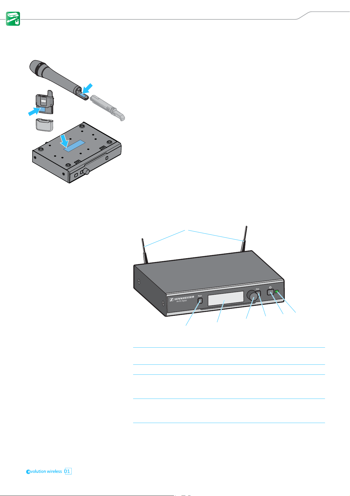
EM D1 rack receiver
Operating elements – front panel
1 2G4 rod antennas for connection to the R-SMA sockets at the rear of the receiver
2 PAIR button Short-press to identify the paired transmitter (see page 29).
Long-press to change the pairing (see page 28).
3 Display panel For details, see page 9.
4 Jog dial Turn to navigate through the menu, to change settings or to change from the
standard display to the extended standard display.
5 ESC button Short-press to navigate to the next higher level in the menu or to exit a menu
6 STANDBY button Short-press to switch the receiver on.
Press to open the menu or to confirm the entry or selection.
item without confirming new settings or entries.
Long-press to exit the menu and to return to the standard display.
Long-press to switch the receiver off.
7
Page 10
Product overviews
8
9
0
A
B
C
D
7 Status LED
lights up green:
flashes green:
flashes alternately
green and red:
lights up yellow:
flashes red:
lights up red:
A radio link to the transmitter is established. The batteries of the received
transmitter are sufficiently charged.
The PAIR button has been short-pressed. Paired devices are being identified.
The PAIR button has been long-pressed. The receiver establishes a radio link
to a transmitter whose PAIR button has also been long-pressed.
The received transmitter has been muted with the MUTE switch. In addition,
Muted is displayed on the display panel.
The battery capacity of the received transmitter is only sufficient for approx.
30 minutes of operation.
No radio link to a transmitter. In addition, the background of the display panel
changes back and forth between light and dark and No Link appears on the
display panel.
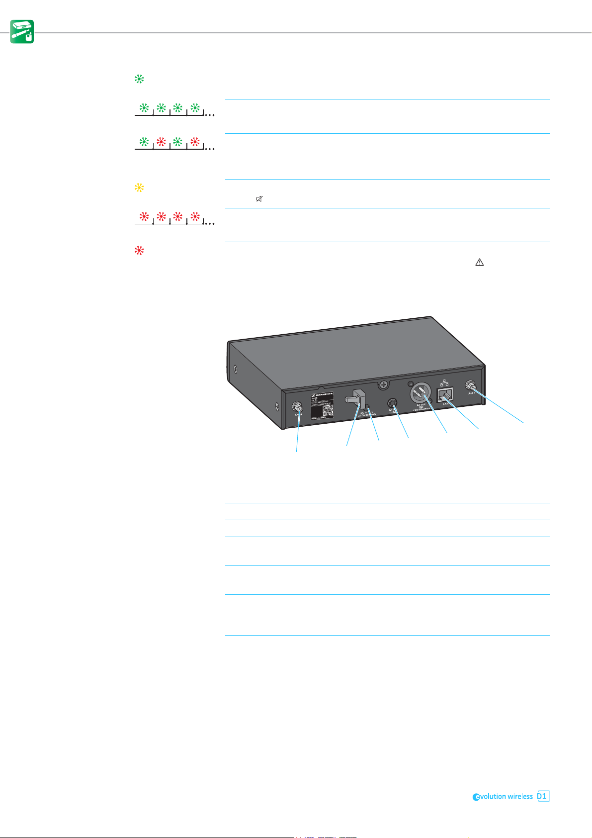
Operating elements – rear panel
8 R-SMA socket ANT II Antenna input II for connecting a supplied 2G4 rod antenna (for details, see
page 16)
9 Cable grip for the cable of the power supply unit
0 DC IN socket for connection of the power supply unit
A ¼" (6.3 mm) jack socket
AF OUT UNBAL
B XLR-3 socket AF OUT BAL Balanced audio output for connection to the XLR-3 input of the mixing console
C Ethernet socket LAN for connecting to a network router or a switch (e.g. to control, monitor and
D R-SMA socket ANT I Antenna input I for connecting a supplied 2G4 rod antenna (for details, see
Unbalanced audio output for connection to the ¼" (6.3 mm) jack input of the
mixing console (for details, see page 20)
(for details, see page 20)
update several receivers via a mobile device or a computer (for details, see
page 20)
page 16)
8
Page 11
Product overviews
15
07
6
B
4
9
8
23
A
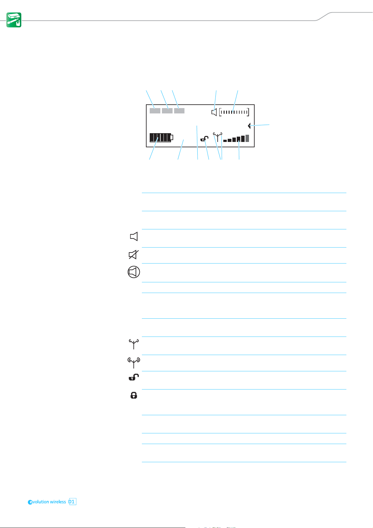
Displays and icons on the receiver's display panel
Standard display The standard display appears automatically after switch-on or when no but-
ton has been pressed on the receiver for a long period of time. The brightness
of the standard display automatically dims after a few minutes.
EQ
DE-S AGC
NAME
10 h
1 Equalizer If one of the equalizer functions is activated, EQ appears in inverse on the
standard display (for details, see page 32).
2 De-esser If one of the de-esser functions is activated, DE-S appears in inverse on the
standard display (for details, see page 33).
3 Auto gain control If one of the compression functions is activated, AGC appears in inverse on the
standard display (for details, see page 33).
4 MUTE The received transmitter is not muted, but can be muted at any time (for
details, see page 28).
The received transmitter is muted. In addition, the status LED lights up yellow.
The received transmitter cannot be muted because its MUTE switch is deactivated (for details see page 35).
5 Audio level display The audio level is automatically optimally adjusted.
6 Extended standard display The extended standard display appears when you turn the jog dial to the left
(see page 10). The above shown standard display appears again after 10 seconds or when you turn the jog dial to the right.
7 6-segment RF signal level display Displays the field strength of the received signal. The 6-segment RF signal
level display is also shown on the transmitter display panel.
8 RF output power of the receiver‘s
back channel
9 Lock mode Open padlock icon: The lock mode is temporarily deactivated and the receiver
Medium RF output
power
High RF output power Only displayed by the -NH country variant.
can be operated as usual.
Locked padlock icon: The lock mode is activated. Press and hold the jog dial to
temporarily deactivate the lock mode. To permanently deactivate the lock
mode, see page 34.
If no padlock icon is displayed, the lock mode is permanently deactivated (for
details, see page 34).
Displayed by the -H and -NH10 country variants.
0 Name of the radio link To change this name, see page 32.
This information is only displayed when the transmitter is powered via the
optional accupack (for details, see page 27).
The 7-segment battery or accupack capacity display is also shown on the
transmitter display panel (for details, see page 27).
A Remaining battery life of the received
transmitter
B 7-segment display of the transmitter‘s
battery or accupack capacity
9
Page 12
Product overviews
D
C
EF
123
NT 2-3
NT 12-4C
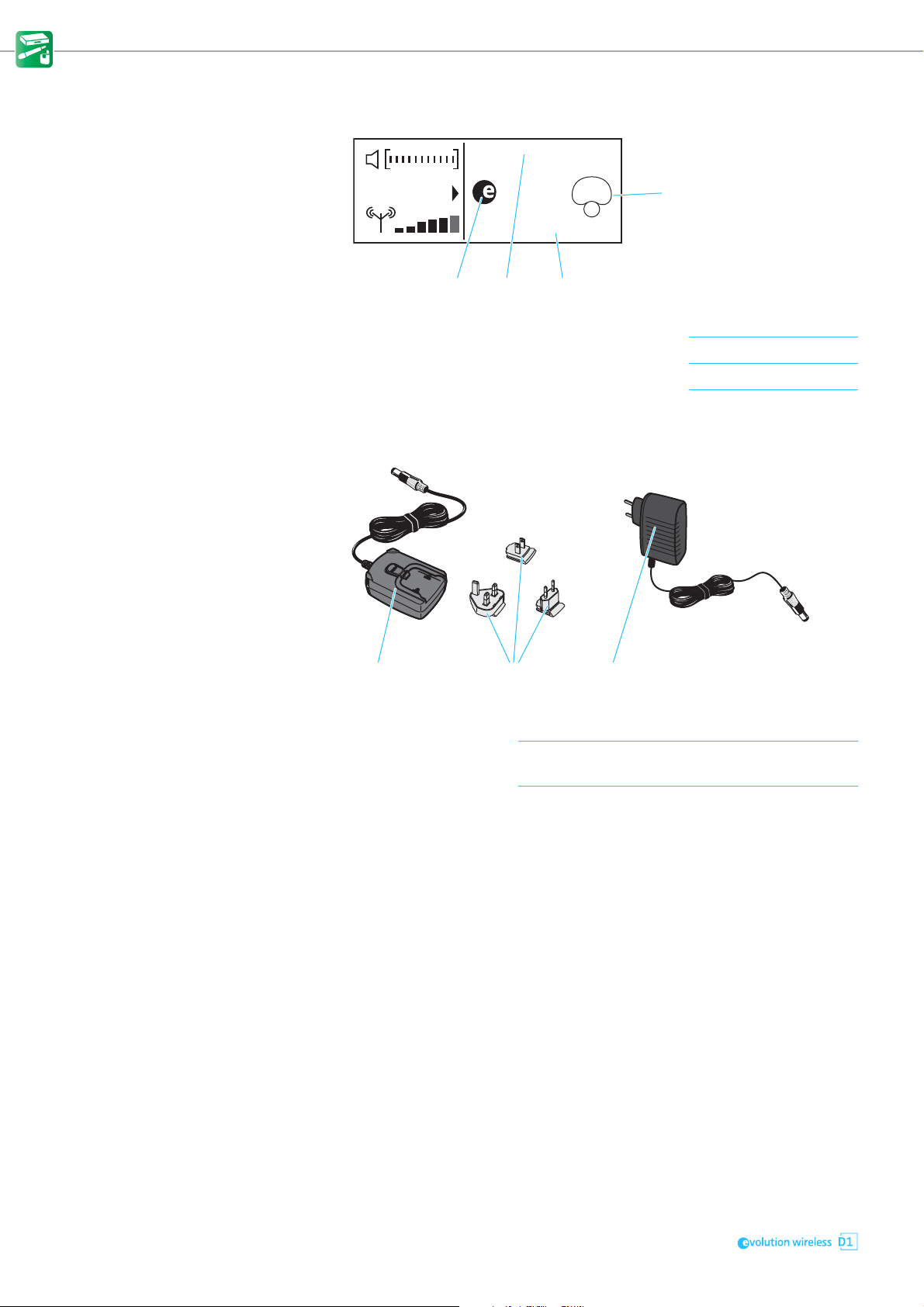
Extended standard display The extended standard display appears when you turn the jog dial to the left.
10 dBAudio out:
845
Low cut filter: Off
C Pick-up pattern of the microphone used For details, see page 24.
D Status of the low-cut filter (ON/OFF) For details, see page 32.
E Output level of the receiver in dB For details, see page 34.
F Product name of the microphone head used For details, see page 24.
Power supply units for the receiver
1 NT 2-3
power supply unit
2 Interchangeable
country adapters
3 NT 12-4C
power supply unit
Not available in Europe, the UK, and the USA.
for plugging onto the NT 2-3
Country-specific variants are available in Europe,
the UK, and the USA.
10
Page 13
Product overviews
1
2
3
4
5
6
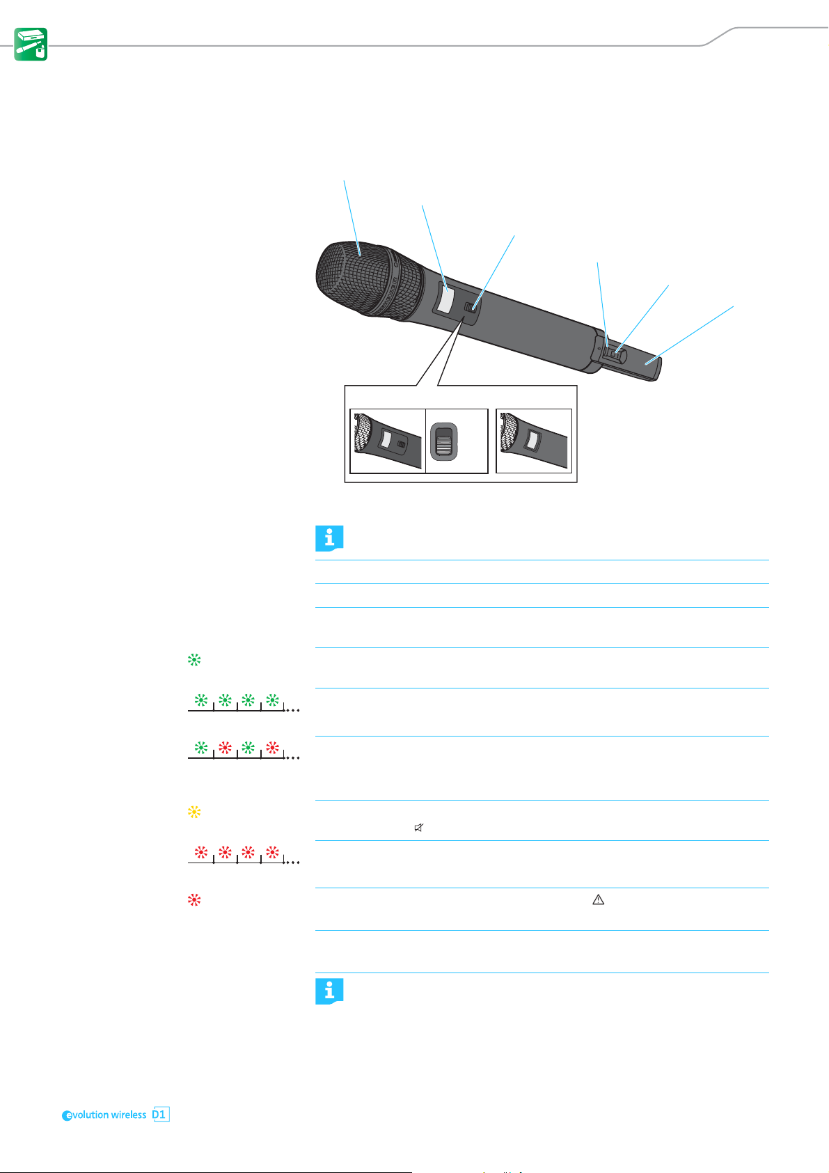
SKM D1, SKM-S D1 and SK D1 transmitters
Operating elements of the SKM D1 and SKM-S D1 handheld transmitters
SKM-S D1
Mic
Mute
1 Unscrewable microphone head For details, see page 24.
Do not cover the microphone head during transmission to avoid changing the characteristics of the pick-up pattern.
2 Display panel For details, see page 13.
3 MUTE switch for muting the SKM-S D1 handheld transmitter (for details, see page 28)
4 ON/OFF button with status LED Short-press to switch the handheld transmitter on.
Long-press to switch the handheld transmitter off (for details, see page 26).
lights up green:
flashes green:
flashes alternately
green and red:
lights up yellow:
A radio link to the receiver is established. The batteries of the handheld transmitter are sufficiently charged.
The PAIR button has been short-pressed. Paired devices are being identified.
The PAIR button has been long-pressed. The handheld transmitter establishes
a radio link to a receiver whose PAIR button has also been long-pressed.
The SKM-S D1 handheld transmitter has been muted with the MUTE switch. In
addition, Muted is displayed on the display panel.
SKM D1
The battery capacity of the handheld transmitter is only sufficient for approx.
5 PAIR button Short-press to identify the paired receiver (see page 29).
6 Antenna Do not touch the antenna during transmission to avoid a reduction in
flashes red:
lights up red:
30 minutes of operation.
No radio link to a receiver. In addition, No Link is displayed on the display
panel.
Long-press to change the pairing (see page 28).
the transmission range.
11
Page 14
Product overviews
1
2
3
4
5
8
9
6
7
7
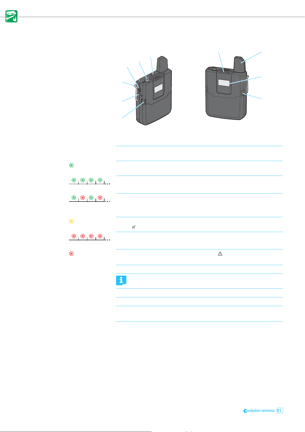
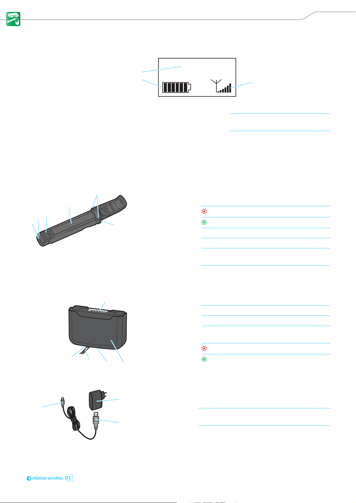
Operating elements of the SK D1 bodypack transmitter
1 ON/OFF button Short-press to switch the bodypack transmitter on.
Long-press to switch the bodypack transmitter off (for details, see page 26).
2 3.5 mm jack socket
Mic/Line
3 Status LED
4 MUTE switch for muting the bodypack transmitter (for details, see page 28)
5 Antenna Do not touch the antenna during transmission to avoid a reduction in
6 Display panel For details, see page 13.
7 Catches Press simultaneously to release the battery box or the accupack.
lights up green:
flashes green:
flashes alternately
green and red:
lights up yellow:
flashes red:
lights up red:
for connecting the clip-on or headset microphone
A radio link to the receiver is established. The batteries of the bodypack transmitter are sufficiently charged.
The PAIR button has been short-pressed. Paired devices are being identified
(for details, see page 29).
The PAIR button has been long-pressed. The bodypack transmitter establishes
a radio link to a receiver whose PAIR button has also been long-pressed (for
details, see page 28).
The bodypack transmitter has been muted with the MUTE switch. In addition,
Muted is displayed on the display panel (for details, see page 28).
The battery capacity of the bodypack transmitter is only sufficient for approx.
30 minutes of operation.
No radio link to a receiver. In addition, No Link is displayed on the display
panel.
the transmission range.
8 PAIR button Short-press to identify the paired receiver (see page 29).
Long-press to change the pairing (see page 28).
9 Belt clip For details, see page 22.
12
Page 15
Product overviews
1
3
2
1
3
4
2
5
6
1
3
2
4
5
1
3
2
Displays of the transmitters
NAME
1 Name of the radio link For details, see page 32.
2 7-segment display of the battery
or accupack capacity
3 6-segment RF signal level display Displays the field strength of the trans-
For details, see page 27.
mitted signal at the receiver.
Optional accessories for the transmitters
BA 10 accupack for the SKM D1 or SKM-S D1 handheld transmitter
1 Micro USB socket with
cover flap
2 Charge status LED
3 Contact surfaces for powering the handheld transmitter
4 Accupack contains the Li-Ion rechargeable battery
5 Catches Press simultaneously to release the accupack from
6 Charging contacts for charging the accupack in the charging unit
BA 30 accupack for the SK D1 bodypack tranmsitter
for charging the accupack with any USB power supply/charger (for details, see page 25)
lights up red: The accupack is being charged
lights up green: The accupack is fully charged
the handheld transmitter.
1 Contact surfaces for powering the bodypack transmitter
2 Accupack contains the Li-Ion rechargeable battery
3 Charging contacts for charging the accupack in the charging unit
4 Micro USB socket with
cover flap
5 Charge status LED
USB power supply/charger for charging the accupacks
1 NT 5-10-U USB power supply/charger (country-specific)
2 USB connector
(type A)
3 Micro USB connector for connection to an accupack
for charging the accupack with any USB power supply/charger (for details, see page 25)
lights up red: The accupack is being charged
lights up green: The accupack is fully charged
for charging the accupacks
for connection to the USB power supply/charger
13
Page 16
Product overviews
1
2
35
7
46
1
2
3
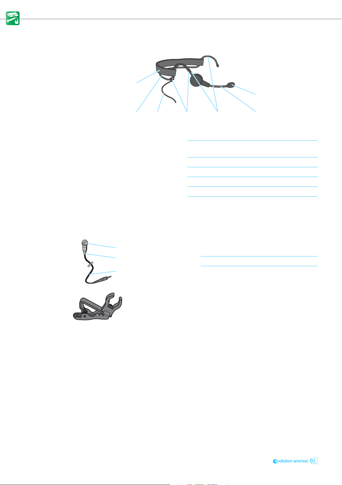
ME 3-II headset microphone
1 Microphone capsule
with windshield
2 Flexible microphone
boom
3 Ear hooks for a secure fit on the ears
4 Clips for attaching the connection cable to the ear hook
5 Connection cable with lockable 3.5 mm jack plug
6 Neckband for a secure fit on the head
7 Neckband padding for a comfortable fit, adjustable in length with a Velcro
with lateral sound inlet and cardioid pick-up pattern
for precise positioning of the microphone at the corner
of the mouth
fastener
ME 2-2 clip-on microphone
1 Microphone capsule with
windshield
2 Anti-kink protection to prevent cable damage
3 Connection cable (1.6 m) with lockable 3.5 mm jack plug for connection to
Supplied with microphone clip to attach the clip-on microphone to clothing.
should be pointed towards the mouth
the bodypack transmitter
14
Page 17
Putting the products into operation
Putting the products into operation
Avoiding sources of interference Featuring automatic interference management, the devices are capable of
avoiding interfering signals at any time by automatically moving together to
unused frequencies in the 2.4 GHz frequency band, without any audio interruption. However, the number of usable radio links is reduced if there are
active sources of interference in the vicinity of the devices.
왘 Switch off possible sources of interference operating in the 2.4 GHz fre-
quency band.
Possible sources of interference use e.g. WiFi or Bluetooth.
Infrared remote controls and headphones, DECT headphones and UHF radio
links (e.g. Sennheiser evolution wireless G3) do not represent a source of
interference and can remain switched on.
You can identify and locate sources of interference using a WiFi scanning tool.
왘 If you want to use WiFi while operating devices of the
series, use a dual-band WiFi router and deactivate its 2.4 GHz frequency
band in order to minimize interference to the radio links.
If conditions are optimal, you can operate up to 15 radio links simultaneously
(for details, see “Using the devices in multi-channel operation” on page 29).
Direct line of sight recommended Walls and other obstacles will reduce the range. Therefore, there should
always be a direct line of sight between the transmitting antenna and the
receiving antennas of a radio link. To ensure this, you can mount the antennas
of the receiver in different ways.
• When using the EM D1 as a stand-alone receiver, you can mount the sup-
plied 2G4 rod antennas to the rear of the receiver (see page 16).
• When rack-mounting the receiver, you should use the GA 4 rack-mount kit
to mount the receiver antennas to the front of the rack (see page 19).
15
Page 18
Putting the products into operation
1
Putting the receiver into operation
Fitting the device feet
ATTENTION
Risk of staining of furniture surfaces!
Some furniture surfaces have been treated with varnish, polish or synthetics
which might cause stains when they come into contact with other synthetics.
Despite a thorough testing of the synthetics used by us, we cannot rule out
the possibility of staining.
왘 Do not place the receiver on delicate surfaces.
Do not fit the device feet when mounting the receiver into a rack.
왘 Clean the recesses for the device feet at base of the receiver.
왘 Fit the device feet to the recesses of the receiver.
왘 Place the receiver on a flat, horizontal surface.
The device feet will adhere reliably to the receiver only after some time.
Avoid moving the receiver during this time.
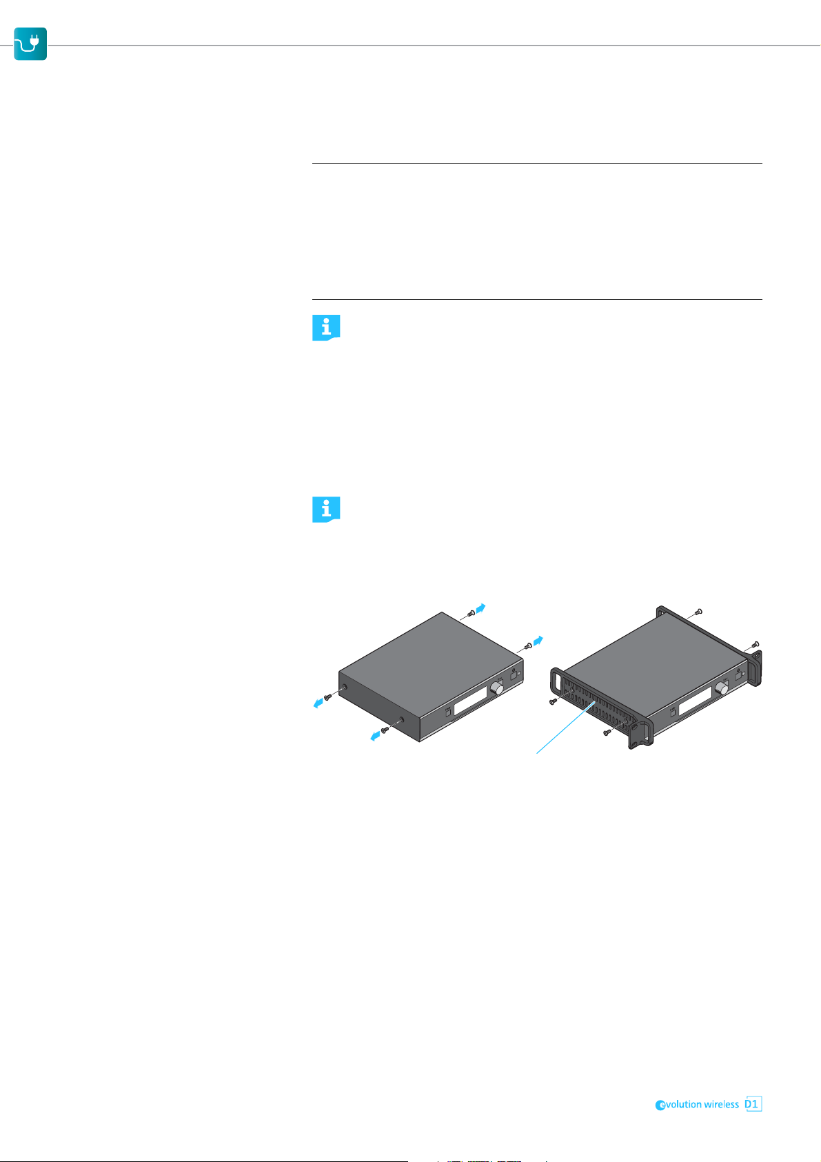
Mounting the rack mount “ears”
The rack mount “ears” are designed to help protect the operating elements from damage or deformation, e.g. if the receiver is dropped.
왘 Therefore, always fasten the rack mount “ears”, even if you do not
want to rack mount the receiver.
To fasten the rack mount “ears”:
왘 Unscrew and remove the two recessed head screws on each side of the
receiver.
왘 Secure the rack mount “ears” 1 to the sides of the receiver using the pre-
viously removed recessed head screws.
Connecting the rod antennas to the receiver
16
The supplied 2G4 rod antennas can be mounted quickly and easily. The rod
antennas are suitable for all applications where – good reception conditions
provided – a wireless transmission system is to be used without a large
amount of installation work
Page 19

Putting the products into operation
1
3
4
6
5
7
8
9
2
왘 Connect the supplied 2G4 rod antennas to the two R-SMA sockets at the
rear of the receiver.
왘 Align the 2G4 rod antennas vertically upwards.
When rack-mounting the receiver, you should use the GA 4 rack-mount
kit to mount the receiver antennas to the front of the rack (see next
chapter).
Mounting the receiver into a 19" rack
ATTENTION
Danger due to high temperature, mechanical loading or electric leakage currents
When rack-mounted, the receivers can be damaged by overheat or excessive
mechanical loading.
왘 Make sure that the temperature within the rack does not exceed the per-
missible temperature limit specified in the specifications (see page 46).
왘 Make sure that the receivers in the rack are not mechanically loaded.
왘 Make sure that circuits are not overloaded by providing overcurrent protec-
tion, if necessary.
왘 Make sure that the sum of the leakage currents of all power supply units do
not exceed the allowable limit values by grounding the rack via an additional ground connection, if necessary.
Do not fit the device feet when mounting the receiver into a 19" rack.
For mounting one or several receiver into a rack, you require the optional GA 4
rack-mount kit. The GA 4 rack-mount kit is supplied with individually purchased receivers and is also available separately as an accessory.
Using the GA 4 rack-mount kit, you can:
• mount a single receiver into a 19" rack (see page 18),
• mount the two 2G4 rod antennas to the front of the rack (see page 19) or
• mount two receivers side by side into a 19" rack (see page 19).
The GA 4 rack-mount kit consists of:
17
Page 20

Putting the products into operation
2
1
7
1 2 rack mount “ears”
2 1 blanking plate
3 1 jointing plate
4 2 R-SMA extension cables
5 Screw-in R-SMA sockets
6 R-SMA connectors with washers and nuts
7 2 blanking plugs for closing off the antenna holes in the blanking plate
8 2 recessed head screws
9 6 recessed head screws
Mounting a single receiver into a rack
왘 Unscrew and remove the four screws located on the sides of the receiver
housing.
왘 Secure the rack mount “ears” 1 to the sides of the receiver using the pre-
viously removed recessed head screws (see right-hand diagram).
Make sure that the angled ends of the rack mount “ears” point forward.
왘 Secure the blanking plate 2 to one of the rack mount “ears” 1 using the
two recessed head screws 8.
Make sure to use the correct side (the one with the round holes) of the
blanking plate 2 to secure it to the rack mount “ear”.
If you want to mount the supplied rod antennas to the front of the rack:
왘 Read the next section.
If you do not want to mount the supplied rod antennas to the front of the rack:
왘 Insert the two blanking plugs 7 into the unused antenna holes.
왘 Slide the receiver into the 19" rack.
왘 Secure the rack mount “ears” 1 and the blanking plate 2 to the rack.
18
Page 21

Putting the products into operation
6
2
1
1
5
3
1
1
Mounting the rod antennas to the front of the rack
When mounting only one receiver into a rack, you can mount the receiver‘s
antenna connections to the front of the rack. This can improve reception.
왘 Screw the two R-SMA sockets 6 of the R-SMA extension cables to the
blanking plate 2 using the supplied washers and nuts.
왘 Connect the two R-SMA connectors 5 to the R-SMA sockets of the receiver.
왘 Slide the receiver into the 19" rack.
왘 Secure the rack mount “ears” to the rack.
왘 Connect the two 2G4 rod antennas to the R-SMA sockets 6 of the blanking
plate 2.
Mounting two receivers into a rack
You can mount two receivers side by side into a rack.
왘 Place the two receivers side by side upside-down onto a flat surface.
왘 Align the jointing plate 3 over the holes in the bottom sides of the receiv-
ers.
The jointing plate must be placed centrally over the two receivers.
왘 Secure the jointing plate 3 to the receivers using the six recessed head
screws 9.
19
Page 22

Putting the products into operation
0
A
왘 Unscrew and remove the four screws located on the sides of the receiver
housings.
왘 Secure the rack mount “ears” 1 to the sides of the receivers using the pre-
viously removed recessed head screws.
Make sure that the angled ends of the rack mount “ears” point forward.
왘 Slide the receivers into the 19" rack.
왘 Secure the rack mount “ears” 1 to the rack using the recessed head
screws 8.
Connecting the receiver to a mixing console
The receiver‘s ¼" (6.3 mm) jack socket 0 and the XLR-3 socket A are connected in parallel, allowing you to simultaneously connect two devices (e.g.
amplifier, mixing console) to the receiver.
왘 Use a suitable cable to connect the mixing console to the ¼" (6.3 mm) jack
socket 0 or the XLR-3 socket A.
6.3 mm XLR
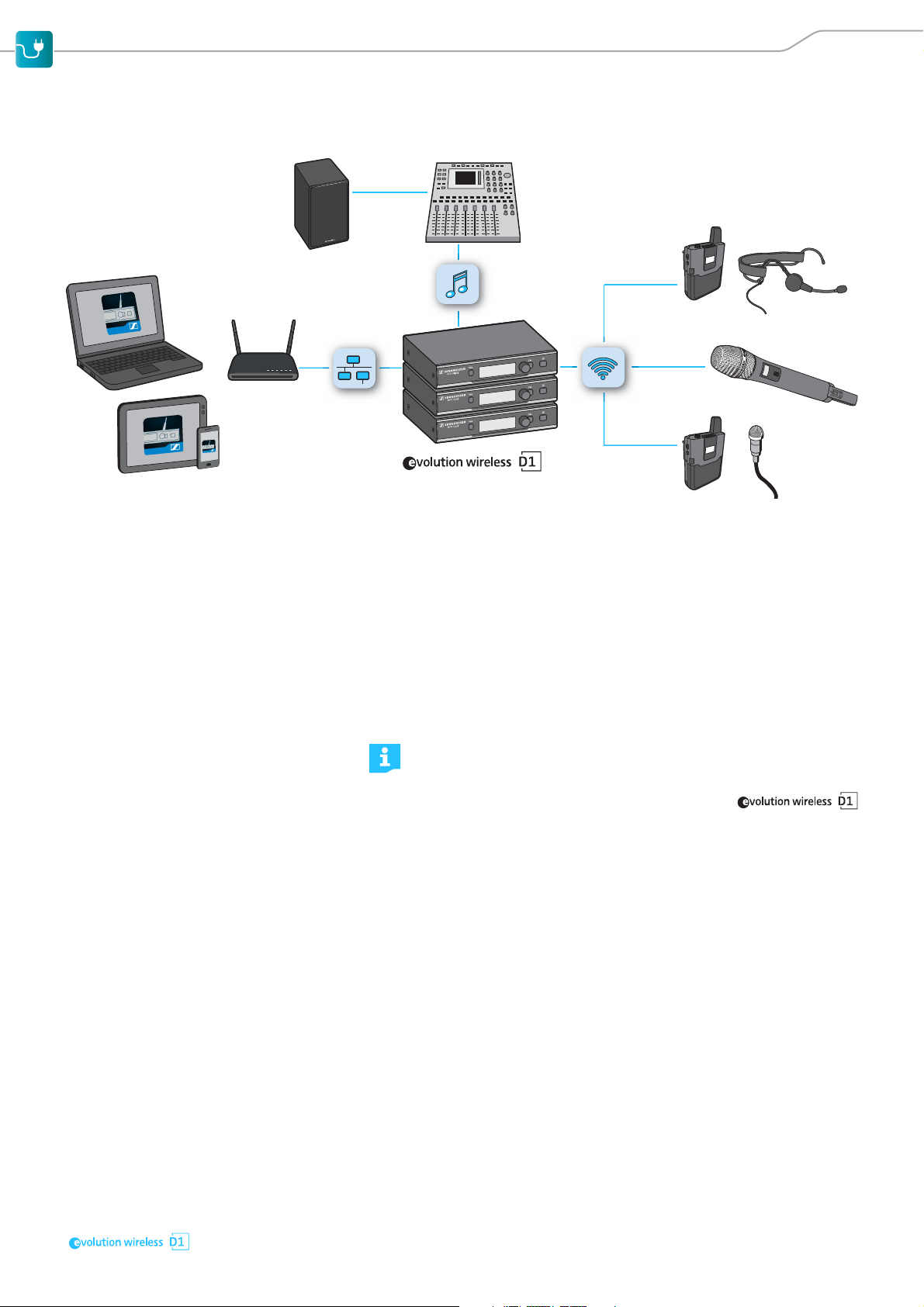
Connecting receivers in a network
You can connect several receivers in a network using a router or a switch. This
allows you to e.g. control, monitor and update all receivers and transmitters
of a multi-channel system via a mobile device or a computer.
“WSR” app Together with the “Wireless System Remote” (WSR) app, you can use one or
several mobile devices to remotely configure all receivers and transmitters of
a multi-channel system, to monitor their operation and to update the firmware of the devices (for details, see page 38).
For this, your require a dual-band WiFi router, a sufficient number of network
cables and at least one mobile device (tablet or smartphone).
“Sennheiser D1 SL Updater” software You can use the “Sennheiser D1 SL Updater” software to update the device
firmware (for details, see page 39).
For this, you require any router or a switch, a sufficient number of network
cables and a computer running Windows 7 or higher.
Updating the firmware without a network
If you do not have a router or a switch and only want to update the
firmware:
왘 Assign the computer a static IP address.
왘 Assign the receiver a static IP address (Network Settings – Mode –
Fixed IP) and then restart the receiver.
왘 Connect the receivers directly to the computer one after the other
and update their firmware.
To connect several receivers in a network using a router or a switch:
20
Page 23

Putting the products into operation
NT 2-3NT 12-4C
왘 Connect a standard network cable (at least Cat 5) to the LAN Ethernet
socket of your receiver.
왘 Connect your receiver to the Ethernet switch or the dual-band WiFi router.
왘 Connect either a computer to the Ethernet switch or connect the computer
or the mobile devices to the WiFi router.
The yellow LED at the rear of the receiver indicates the connection status.
Yellow LED … Connection status
... lit The receiver is connected to the network.
... off The receiver is not connected to the network.
왘 Use a strong password and a strong encryption algorithm to protect your
WiFi or your router against unauthorized access.
왘 Deactivate the WiFi router‘s 2.4 GHz frequency band in order to minimize
interference to the radio links.
To update the firmware of your devices:
왘 Establish an Internet connection with your mobile device or computer to
download the current firmware.
Connecting the receiver to the power supply system
Only use the supplied power supply unit (NT 12-4C or NT 2-3). It is designed
for your receiver and ensures safe operation.
If you use the NT 2-3 power supply unit:
왘 Slide the supplied country adapter onto the power supply unit.
To connect the power supply unit:
왘 Pass the cable of the power supply unit through the cable grip as shown on
the left.
왘 Connect the hollow jack plug of the power supply unit to the DC IN socket
of the receiver.
왘 Plug the power supply unit into the wall socket.
21
Page 24

Putting the products into operation
Putting the bodypack transmitter into operation
Removing/inserting the batteries or the optional accupack
You can power the bodypack transmitter with the supplied B 30 battery box
and two 1.5 V AA size batteries.
Optionally, you can also use the Sennheiser BA 30 accupack (3.6 V). The
accupack must be charged before first time use. The accupack can
remain in the bodypack transmitter for charging.
If you use the supplied B 30 battery box to power the bodypack transmitter:
왘 Insert the batteries into the B 30 battery box.
Please observe correct polarity when inserting the batteries.
To remove the battery box or the accupack:
왘 Simultaneously press the two catches and pull the battery box or the accu-
pack away from the bodypack transmitter.
To insert the battery box or the accupack:
왘 Slide the battery box or the accupack onto the bodypack transmitter as
shown.
The battery box or the accupack locks into place with an audible click.
Attaching the bodypack transmitter to clothing
You can use the belt clip to attach the bodypack transmitter to clothing (e.g.
belt, waistband).
Connecting the clip-on microphone or the headset microphone to the bodypack transmitter
Only connect the clip-on microphone or the headset microphone recommended by Sennheiser. These microphones are optimized for the bodypack
transmitter.
22
왘 Connect the jack plug of the clip-on microphone or the headset microphone
to the 3.5 mm jack socket (Mic/Line) of the bodypack transmitter.
왘 Lock the jack plug by screwing down the coupling ring.
Page 25

Putting the products into operation
Preparing the headset microphone for use
Adjusting the microphone boom and the neckband padding
For best possible comfort and optimum fit of the headset microphone, the
neckband padding and the microphone boom have to be adjusted to properly
fit your head.
ATTENTION
Damage to the microphone boom
The microphone boom can break or be impaired in its function when you bend
or turn it. Frequent alternate bendings close to the microphone head can also
damage the microphone boom and possibly reduce the adjustability of the
microphone.
왘 Only adjust the microphone boom as described in this chapter.
왘 Put on the headset microphone and adjust it so that a comfortable and
secure fit is ensured.
Make sure to wear the neckband padding around the back of your head. If
the neckband padding is worn too close to the top of the head, it can slip
out of position.
왘 Change the length of the headband padding by means of the Velcro fas-
tener to ensure a snug and comfortable fit.
2–3 cm
왘 Adjust the microphone boom so that the sound inlet points towards the
mouth and is positioned approx. 2 to 3 cm from the corner of the mouth.
Using the windshield
The windshield attenuates annoying wind noise by 10 dB.
왘 Slip the windshield onto the microphone capsule.
Attaching the clip-on microphone to clothing
The ME 2-2 clip-on microphone is supplied with a microphone clip.
왘 Use the microphone clip to attach the clip-on microphone to clothing (e.g.
tie, lapel).
왘 Conduct the cable so that noise due to friction is avoided and that the con-
nection cable and the antenna do not cross.
왘 Attach the microphone at a distance of approx. 20 cm to the mouth.
The clip-on microphone has an omni-directional pick-up pattern. It is therefore not necessary to position it precisely.
23
Page 26

Putting the products into operation
5-10 cm
Putting the handheld transmitter into operation
If you touch the antenna of the handheld transmitter during transmission, the
transmission range will be considerably reduced. If you cover the microphone
head during transmission, this will change the pick-up pattern of the microphone and consequently the sound.
왘 Only hold the handheld transmitter by its body.
왘 Hold the handheld transmitter approx. 5 to 10 cm in front of your mouth.
The MMD 845-1 and MMD 945-1 microphone heads have a super-cardioid
pick-up pattern.
왘 Hold the handheld transmitter vertically and speak into the sound inlet
basket from directly above.
The MMD 835-1 and MMD 935-1 microphone heads have a cardioid pick-up
pattern.
왘 You can speak into the sound inlet basket from directly above or from
slightly off-axis.
Removing/inserting the batteries or the optional accupack
You can power the handheld transmitter with the supplied B 10 battery box
and two 1.5 V AA size batteries.
Optionally, you can also use the Sennheiser BA 10 accupack (3.6 V). The
accupack must be charged before first time use (see page 25).
To remove the battery box or the accupack:
왘 Simultaneously press the two catches and pull the battery box or the accu-
pack away from the handheld transmitter.
If you use the supplied B 10 battery box:
왘 Insert the batteries into the B 10 battery box.
Please observe correct polarity when inserting the batteries.
왘 Close the battery box.
To insert the battery box or the accupack:
왘 Slide the battery box or the accupack onto the handheld transmitter as
shown.
The battery box or the accupack locks into place with an audible click.
Changing the microphone head
The handheld transmitter comes in different sets, including either the
MMD 835-1, MMD 845-1, MMD 935-1 or the MMD 945-1 microphone head.
You can unscrew the microphone head and replace it by another one, e.g. one
with a different pick-up pattern.
24
Page 27

Putting the products into operation
Recharging the accupack
If you use the optional BA 10 or BA 30 accupacks, you can charge them via a
standard USB power supply/charger or via the USB port of a computer.
The BA 30 accupack of the bodypack transmitter can remain in the bodypack
transmitter for charging. To charge the BA 10 accupack of the handheld transmitter:
왘 Remove the accupack from the handheld transmitter (see page 22).
왘 If the accupack‘s micro USB socket has a cover flap: Open the cover flap of
the micro USB socket and connect the micro USB connector of the USB cable
to the micro USB socket of the accupack.
왘 Connect the USB connector of the USB cable to the USB socket of the USB
power supply/charger or to the USB port of a computer.
왘 Plug the USB power supply/charger into the wall socket.
The charge status LED lights up red when the accupack is being charged.
The charge status LED lights up green when the accupack is fully charged.
25
Page 28

Using the products
SHORT = ON
Using the products
The Sennheiser series offers true ease of use: The devices
of a set are already paired and are therefore ready for immediate use. The
receiver features automatic frequency management and continually scans the
RF environment for usable, interference-free frequencies. To ensure optimum
levels, the transmitters automatically set the correct microphone sensitivity.
Switching the devices on or off
After switch-on, the receivers and transmitters will take approx.
10 seconds to establish the radio links. The more devices are switched
on, the longer it takes to establish all the radio links.
Switching the receiver on
왘 Short-press the STANDBY button.
After switch-on, the display panel first shows a logo and then the standard
display (see page 9). The status LED indicates the current status of the
receiver (see page 8). The radio link to the last paired transmitter is established automatically as soon as the paired transmitter is switched on.
SHORT = ON
LONG = OFF
LONG = OFF
Switching the receiver off
왘 Long-press the STANDBY button.
The display panel and the status LED go off.
Switching the bodypack transmitter on
왘 Short-press the ON/OFF button.
The standard display appears on the display panel (see page 13). The status LED indicates the current status of the bodypack transmitter (see
page 12). The radio link to the last paired receiver is automatically established as soon as the paired receiver is switched on.
Switching the bodypack transmitter off
왘 Long-press the ON/OFF button.
The display panel and the status LED go off.
Switching the handheld transmitter on
왘 Short-press the ON/OFF button in the direction of the transmitter body.
26
SHORT = ON
The standard display appears on the display panel (see page 13). The status LED indicates the current status of the handheld transmitter (see
page 11). The radio link to the last paired receiver is automatically established as soon as the paired receiver is switched on.
Page 29

Using the products
Switching the handheld transmitter off
왘 Long-press the ON/OFF button in the direction of the transmitter body.
LONG = OFF
The display panel and the status LED go off.
Checking the charge status of the batteries or accupacks
When the capacity of the batteries or the accupack is so low that the remaining battery life is less than 30 minutes, the status LED on both the transmitter
and the receiver flashes red.
In addition, the empty battery icon flashes on the display panel of both the
receiver and the transmitter.
Battery status display If you power the transmitter with batteries, a 6-segment battery icon is
shown on the display panel of both the receiver and the transmitter:
EQ
DE-S AGC
NAME
Accupack status display If you power the transmitter with the optional accupack, the expected battery
life is shown on the display panel of both the transmitter and the receiver:
EQ
DE-S AGC
NAME
10 h
NAME
NAME
10 h
Checking the RF signal level
The field strength of the RF signal received by the receiver is shown on the display panel of both the receiver and the transmitter.
EQ
DE-S AGC
NAME
8 h
If no RF signal is being received, e.g. because the paired device is switched off
or out of range, all segments of the RF signal level display are grayed out. In
addition, the background of the display panel changes back and forth
between light and dark and No Link appears on the display panel.
NAME
27
Page 30

Using the products
Muting the bodypack transmitter or the SKM-S D1 handheld transmitter
Both the bodypack transmitter and the SKM-S D1 handheld transmitter have
a MUTE switch that mutes the audio signal without switching the transmitter
off.
In order that a transmitter can be muted, its MUTE switch must be activated (see page 35). If you try to mute a transmitter whose MUTE
switch is deactivated, Mute disabled appears on the display panel of
both the transmitter and the receiver.
The SKM D1 handheld transmitter has no MUTE switch and can therefore not be muted.
왘 Slide the MUTE switch to the position MUTE.
Muted appears on the display panel of both the transmitter and the
paired receiver. The status LED on both the transmitter and the paired
receiver lights up yellow.
왘 Slide the MUTE switch back to the initial position to unmute the audio sig-
nal.
Pairing a receiver with a transmitter
The receiver and the transmitter of a set are factory pre-paired and
therefore ready for immediate use. The radio link is automatically
established as soon as both devices are switched on. You can disconnect the existing radio link and establish new radio links to two other
devices.
To establish a new radio link between a receiver and a transmitter, proceed as
follows:
왘 Switch on the receiver and the transmitter that you want to pair (see
page 26).
The status LED on both the receiver and the transmitter indicates the current device status (see page 8).
왘 Long-press the PAIR button of the receiver until its status LED flashes alter-
nately green and red.
Identify appears on the display panel of the receiver, followed by the message Pairing. An existing radio link is now disconnected. You now have
90 seconds to establish a radio link with a new transmitter.
왘 Long-press the PAIR button of the transmitter until its status LED flashes
alternately green and red.
Press pair on receiver appears on the transmitter display panel.
왘 Wait for approx. 10 seconds until the radio link is established.
- Once the radio link is successfully established, Paired appears on the
display panel of both the receiver and the transmitter and the status LED
on the transmitter and the receiver lights up green.
- If no radio link can be established, Pairing failed appears on the dis-
play panel of both the receiver and the transmitter and the status LED on
the transmitter and/or the receiver lights up red.
- If you try to pair devices that are running incompatible firmware versions, a message appears on the display panel prompting you to update
the firmware of the transmitter. If you update the firmware now, the
transmitter and the receiver will be paired afterwards; if you do not
update the firmware, the transmitter and the receiver will not be paired
and FW mismatch appears on the display panel of the receiver.
28
Page 31

Using the products
NAME
EQ
DE-S AGC
10 h
Low cut filter: Off
10 dBAudio out:
845
ATTENTION
Breakdown of radio links during the firmware update
All radio links are subject to interference during the firmware update process and can therefore not be used for audio transmission.
왘 Never update the firmware during a performance.
Identifying paired devices
You can perform a pairing identification to see which transmitter is paired
with which receiver.
왘 Switch on all devices whose pairing you want to identify (see page 26).
왘 Short-press the PAIR button of the receiver or of the transmitter.
The status LEDs of the paired devices flash for 10 seconds. Identify appears
on the receiver display panel. This is plus the name of the radio link appear
on the transmitter display panel.
If the receiver or the transmitter is not paired or if the paired device is not
switched on or out of range, the display panel changes back to the standard
display after 10 seconds.
Using the devices in multi-channel operation
If you only want to use up to six radio links simultaneously, you do not have
to follow a special switch-off/switch-on sequence. If you want to use more
than six radio links simultaneously, you may have to follow a special switchoff/switch-on sequence.
왘 Proceed as described in the enclosed “Multichannel Operation” leaflet.
Switching between the standard display and the extended standard display
To switch from the standard display to the extended standard display:
왘 Turn the jog dial to the left.
After 10 seconds, the display panel automatically changes from the
extended standard display back to the standard display.
To manually change from the extended standard display back to the standard
display before 10 seconds have elapsed:
왘 Turn the jog dial to the right.
29
Page 32

Using the products
Standard display
(see page 9)
Extended standard display
(see page 10)
Using the operating menu of the receiver
Using the buttons for navigation
Button Function
• Short-press: Switches the receiver on
Press the
STANDBY button
SHORT
esc
Short-press the
ESC button
LONG
esc
Long-press the
ESC button
Press the jog dial
Turn the jog dial
• Long-press: Switches the receiver off
• Navigates to the next higher level in the menu
• Exits the menu item without storing changes to
the settings
• Returns to the standard display
• Changes from the current standard display to
the operating menu
• Calls up the selected menu item
• Changes to the selected submenu
• Switches between the standard display and the
extended standard display
• Changes to the previous or next menu item
• Changes the settings of a menu item
Overview of the operating menu of the receiver
Home
Level 1
Audio
Settings
Level 2
Low Cut
Equalizer
De-Esser
Auto Gain
Control
Effects
Reset
System
Settings
Auto Lock
Mute
Switch
Display
Brightness
Help
System
Info
Network
Settings
Mode
IP
Subnet
Gateway
IPv6
Walk TestName
30
Audio
Level
Output
Type
Factory
Reset
MAC
Page 33

Using the products
Level 1 Level 2 To ... See …
Audio
Settings
System
Settings
Network
Settings
Name – change the name of the radio link page 32
Walk
Test
Exit – exit the operating menu and return to
Low Cut filter out low-frequency noise page 32
Equalizer select a sound profile or manually
adjust the equalizer
De-Esser attenuate sibilants page 33
Auto Gain
Control
Effects Reset reset all audio settings to the factory
Audio Level fine-tune the receiver‘s output level page 34
Output Type adjust the receiver‘s output level to
Exit exit Level 2 and return to Level 1
Auto Lock activate/deactivate the automatic lock
Mute Switch activates/deactivate the transmitter‘s
Display
Brightness
Help display the QR codes for the help
System Info display the firmware version and serial
Factory Reset reset the receiver to the factory default
Exit exit Level 2 and return to Level 1
Mode change the IP address assignment
IP change the IP address page 36
Subnet change the subnet mask page 36
Gateway change the gateway address page 37
IPv6 display the IPv6 address page 37
MAC display the MAC address page 37
Exit exit Level 2 and return to Level 1
– check the reception quality within the
activate/deactivate the dynamic compression
default settings
match the input (mic or line) of the
connected device
mode
MUTE switch
change the brightness of the display
panel
functions
number
settings
mode
operating environment
the standard display
page 32
page 33
page 33
page 34
page 34
page 35
page 35
page 35
page 36
page 36
page 36
page 37
31
Page 34

Using the products
DEL SAVE
Name
O
Audio
F
G
HANDHELD
I
utput Type
Exit
Low Cut
Equalizer
-
On
Off
Changing the name of the radio link
You can change the name of the radio link. This name is displayed on the display panels of the paired devices.
왘 Select Name.
왘 Select and confirm the character that you want to change. Then select the
new character.
You can enter up to 8 capital letters from A to Z and digits from 0 to 9.
To delete the selected character:
왘 Select DEL and confirm by pressing the jog dial.
To store the entered name:
왘 Select SAVE and confirm by pressing the jog dial.
Activating/deactivating the low-cut filter
You can filter out low-frequency noise caused, for example, by the proximity
effect of the microphone or by wind.
왘 Select Audio Settings – Low Cut.
Setting Meaning
On The low-cut filter is activated. Low-frequency noise is fil-
tered out.
This setting is recommended if you mainly want to transmit
speech.
Off The low-cut filter is deactivated. Low-frequency noise is not
filtered out.
This setting is recommended if you want to transmit music
or sound effects with a dominant bass component.
Audio
Low Cut
Equalizer
De-Esser
Exit
On
Off
Adjusting the equalizer
You can adjust a sound profile to e.g. improve speech intelligibility or adjust
the sound to the room acoustics.
왘 Select Audio Settings – Equalizer.
You can select an existing sound profile or manually adjust the equalizer.
To select an existing sound profile:
왘 Select the desired sound profile.
If one of the equalizer functions is activated, EQ appears in inverse on the
standard display.
To manually adjust the equalizer:
왘 Select Custom.
The equalizer is displayed.
32
Page 35

Using the products
L
t
+12
-12
0
50
EQUALIZER
125 315 800
2k 5k
10k SAVE
왘 Select one of the seven frequencies (50, 125, 315, 800, 2k, 5k or 10k) and
press the jog dial.
+15
dB
+10
+5
0
–5
–10
–15
20 50 200 500 2k 5k 20k
100 1k 10k
Hz
50 Hz
125 Hz
315 Hz
800 Hz
2 kHz
5 kHz
10 kHz
왘 Turn the jog dial to increase or reduce the selected level.
Turning the jog dial by one notch increases or reduces the level by 1 dB. You
can increase or reduce the level by a maximum of 12 dB. Your setting is represented by bars.
왘 Press the ESC button.
왘 Select the next frequency and repeat the steps.
왘 Once you have adjusted all frequency bands as desired, confirm with SAVE.
Audio
Audio
Audio
ow Cu
Equalizer
De-Esser
Auto Gain Control
Equalizer
De-Esser
Auto Gain Control
Effects Reset
De-Esser
Auto Gain Control
Effects Reset
Audio Level
Off
On
Off
Off
Off
On
On
On
10 dB
Adjusting the de-esser
You can attenuate sibilance in vocals and speech.
왘 Select Audio Settings – De-Esser.
왘 Select the desired profile.
If one of the de-esser functions is activated, DE-S appears in inverse on the
standard display.
Activating/deactivating the dynamic compression
You can activate one of the dynamic compression profiles in order to boost
very quiet passages and to attenuate particularly loud passages. You can
choose from preset profiles for different situations.
왘 Select Audio Settings – Auto Gain Control.
왘 Select the desired profile.
If one of the dynamic compression profiles is activated, AGC appears in
inverse on the standard display.
Resetting the audio settings
The Effects Reset menu item allows you to reset the receiver‘s audio settings
made in the Audio Settings menu to the factory default settings. All other
receiver settings remain unchanged.
33
Page 36

Using the products
Exit
Audio
D
Audio
Effects Reset
Audio Level
Output Type
Exit
Auto Gain Control
Effects Reset
Audio Level
Output Type
10 dB
Line
Off
10 dB
Line
Coarsely adjusting the output level of the receiver (Mic/Line)
You can coarsely adjust the output level of the receiver to match the input
(mic or line) of the connected mixing console.
왘 Select Audio Settings – Output Type.
Setting Meaning
Line The output level is adjusted to match a line input.
Mic The output level is adjusted to match a mic input.
Fine-tuning the output level of the receiver
You can fine-tune the output level of the receiver to match the input (mic or
line) of the connected mixing console.
왘 Select Audio Settings – Audio Level.
왘 Turn the jog dial to increase or reduce the audio level.
Turning the jog dial by one notch increases or reduces the audio level by
1 dB. You can adjust the audio level between 0 dB and 30 dB.
EQ
DE-S AGC
System
NAME
10 h
ebug Mode
Auto Lock
Mute Switch
Exit
Off
Active
Activating/deactivating the lock mode
The receiver is delivered with the lock mode deactivated. This is indicated by
the open padlock icon on the standard display as shown on the left.
To activate the lock mode:
왘 Select System Settings – Auto Lock – On.
Stored appears on the display panel. The open padlock icon appears
on the standard display for 10 seconds. If, during these 10 seconds, no button is actuated on the receiver, the lock mode is activated and the locked
padlock icon appears on the standard display.
The lock mode prevents that the receiver is accidentally switched off or that
settings are inadvertently changed during operation. If one of the receiver
buttons is actuated while the lock mode is activated, Locked and To
unlock press & hold SET appears on the display panel of the receiver.
To temporarily deactivate the lock mode:
왘 Long-press the jog dial.
Unlocked appears on the display panel.
The open padlock icon appears on the standard display and the lock
mode is deactivated for 10 seconds. If, during these 10 seconds, no button
is actuated on the receiver, the lock mode is automatically activated again.
To permanently deactivate the lock mode:
왘 If the lock mode is temporarily deactivated, select System Settings – Auto
Lock – Off.
Stored appears on the display panel. The lock mode icon no longer
appears on the standard display.
34
Page 37

Using the products
Auto Lock
Mute Switch
Display Brightness
Off
Active
75
System
Exit
Activating/deactivating the MUTE switch of the transmitter
From the receiver, you can activate or deactivate the MUTE switch of the
received transmitter. This setting determines whether or not the transmitter
can be muted.
왘 Select System Settings – Mute Switch.
Setting Meaning
Active The MUTE switch of the transmitter is activated.
Depending on the position of the MUTE switch of the received
transmitter, either the icon for a muted transmitter ( ) or the
icon for an unmuted transmitter ( ) appears on the standard
display.
Deactivated The MUTE switch of the transmitter is deactivated. The follow-
ing icon appears on the standard display:
If the MUTE switch of the transmitter is actuated, Mute
disabled appears on the display panel of the receiver.
Adjusting the display brightness
System
System
Auto Lock
Mute Switch
Display Brightness
Help
Mute Switch
Display Brightness
Help
System Info
Off
Active
75
Active
75
The brightness of the receiver display panel can be adjusted in 16 steps.
왘 Select System Settings – Display Brightness.
Turning the jog dial by one notch increases or reduces the brightness by
5%. The brightness can be reduced to a minimum of 25%.
The brightness automatically dims after a few minutes.
Calling up help functions
For more information and help on the use and operation of your receiver or
your system, you can call up different help functions by
scanning the QR codes displayed on the receiver display panel or by following
the links given below.
왘 Select System Settings – Help.
왘 Select the desired help function.
Selection Help function QR code Link
Setup
Guide
You are redirected
to the page for
sennheiser.com/D1-setup
downloading the
setup guide.
Operation
Manual
You are redirected
to the page for
sennheiser.com/D1-manual
downloading this
system manual.
FAQ &
Support
Mobile
App
You are redirected
to the FAQ/support page.
You are redirected
to the page for
downloading the
app for your
mobile device.
sennheiser.com/D1-support
sennheiser.com/D1-app
35
Page 38

Using the products
Exit
75
System
MAC
D3
Exit
Display Brightness
Help
System Info
Factory Reset
왘 Use a QR scanner (e.g. your smartphone or a reading device for QR codes)
to scan the QR code that appears on the receiver display panel or follow the
given link in your browser.
Alternatively, you can click on the desired link in the above table.
Retrieving system information
You can display the serial number and the current firmware version of the
receiver.
왘 Select System Settings – System Info.
The serial number as well as the version number and the date of the current
firmware are displayed.
왘 Press the ESC button to return to the operating menu.
Resetting the receiver to the factory default settings
Help
System Info
System
Factory Reset
Exit
Changing the IP address assignment
mode
00:1B:66:7D:56:
Exit
Network
Mode
IP
Fixed IP
0.0.0.0.
Changing the IP address You can change the IP address of the receiver. The new IP address becomes
Network
Mode
IP
Subnet
Fixed IP
0.0.0.0.
0.0.0.0.
The System Settings – Factory Reset menu item allows you to reset the
receiver to its factory default settings.
After the reset, the receiver is restarted and the standard display is shown on
the display panel.
Changing the network configuration
If you change a setting in the Mode, IP, Subnet and Gateway submenus of the Network Settings menu, you will be prompted to restart
the receiver.
왘 Switch the receiver off and on again so that changes to the network
configuration take effect.
You can choose between static and dynamic IP address assignment.
왘 Select Network Settings – Mode.
Setting Meaning
Fixed IP The receiver is assigned a static IP address. You can enter the
static IP address via the IP menu item.
Automatic When switched on, the receiver is automatically assigned a
dynamic IP address.
effective only if Fixed IP has been selected in the Mode menu item.
왘 Select Network Settings – IP.
왘 Enter the IP address.
왘 Select Save and confirm by pressing the jog dial.
36
Changing the subnet mask You can change the subnet mask of the receiver.
왘 Select Network Settings – Subnet.
왘 Enter the subnet mask.
왘 Select Save and confirm by pressing the jog dial.
Network
Mode
IP
Subnet
Gateway
Fixed IP
0.0.0.0.
0.0.0.0.
0.0.0.0.
Page 39

Using the products
Exit
Subnet
Gateway
IPv6 1188:80F3:1388:...
MAC 00:1B:66:7D:56:D3
0.0.0.0
0.0.0.0
Network
Network
Exit
Changing the gateway address You can change the gateway of the receiver.
Network
IP
Subnet
Gateway
IPv6 1188:80F3:1388:...
MAC 00:1B:66:7D:56:D3
0.0.0.0.
0.0.0.0.
0.0.0.0.
왘 Select Network Settings – Gateway.
왘 Enter the gateway address.
왘 Select Save and confirm by pressing the jog dial.
Displaying the IPv6 address
왘 Select Network Settings – IPv6.
The IPv6 address is displayed, but it cannot be changed.
왘 Press the ESC button to return to the operating menu.
Displaying the MAC address
Gateway
IPv6 1188:80F3:1388:...
MAC 00:1B:66:7D:56:D3
WALKTEST
0.0.0.0
왘 Select Network Settings – MAC.
The MAC address is displayed, but it cannot be changed.
왘 Press the ESC button to return to the operating menu.
Performing a walk test (checking the reception quality)
The Walk Test menu item allows you to check the reception quality of your
radio links within the operating environment. By performing a walk test, you
can verify the range and coverage of the radio links.
왘 Switch on the transmitters and receivers of all radio links that you want to
use. In addition, switch on all other devices that you want to use in the
operating environment.
왘 Select Walk Test on all receivers that you want to use for the walk test.
The RF signal level display appears on the display panel of both the receiver
and the transmitter.
왘 Walk the operating environment with one or several paired transmitters.
The RF signal level display on the display panel of both the receiver and the
transmitter is continuously updated.
왘 Check the RF signal level display for more detailed information on the
reception quality:
- Good reception quality is indicated by a tick ( ).
- If the tick is missing, reception quality is sufficient.
- If reception quality is or was compromised at any position, this is indicated by a warning triangle ( ). The warning triangle remains displayed
on the display panel even if reception quality improves afterwards.
- If reception fails completely, the background of the display panel changes
back and forth between light and dark and No Link appears on the display panel.
왘 Press the ESC button on the receiver to end the walk test.
If the result of the walk test is not satisfying, you can take the following
remedial measures:
• If possible, reposition the receivers so that there is always a direct
line of sight between the receiving antennas and the paired transmitter.
• If possible, remove obstacles between the transmitter and the
receiving antennas.
• When rack-mounting receivers, you should mount their SG4 rod
antennas to the front of the rack using the GA 4 rack-mount kit.
37
Page 40

Using the products
. . .
2.4 GHz or
5 GHz
(recommended)
Network connection
via a router or switch
Wireless System
Remote (WSR)
Sennheiser
D1 SL Updater
Controlling, monitoring or updating devices via the network
You can control, monitor and update multiple receivers and their paired transmitters via the network.
“Sennheiser D1 SL Updater” software You can use the “Sennheiser D1 SL Updater” software to update the firmware.
“WSR” app Together with the “Wireless System Remote” (WSR) app, you can use one or
several mobile devices to remotely configure all receivers and transmitters of
a multi-channel system, to monitor their operation, or to update the firmware
of the devices.
Monitoring device
The free “Wireless System Remote” (WSR) app is available in the Apple App
Store. Compatible mobile devices and operating systems:
• Apple iPad 2, iPad Air, iPad Air 2, iPad mini, iPad mini 2 or iPad mini 3 Apple
iPhone 4, 4S, 5, 5S, 5C, 6, 6 Plus with iOS 6 or higher
Devices with old hardware may not offer a smooth and fast user
experience due to their limited processing power.
To control, monitor and update your receivers and transmitters using mobile
devices:
왘 Connect all receivers to a WiFi router as described on page 20.
s using the “WSR” app
38
Page 41

Using the products
왘 Use a dual-band WiFi router and deactivate its 2.4 GHz frequency band in
order to minimize interference to the radio links.
왘 Connect your mobile devices to the WiFi network and install the “Wireless
System Remote” (WSR) app.
All functions that can be performed directly from the receiver can also be
controlled via the app.
When started, the “WSR” app automatically checks for newer firmware. You can update both the receiver firmware and the transmitter
firmware (see next chapter).
Performing firmware updates
ATTENTION
Breakdown of radio links during the firmware update
All radio links are subject to interference during the firmware update process
and can therefore not be used for audio transmission.
왘 Never update the firmware during a performance.
왘 Never update the firmware of several transmitters simultaneously.
Breakdown of multi-channel systems due to different firmware versions
All transmitters and receivers of a multi-channel system must run the same
firmware version.
왘 Always update all your transmitters and receivers to the latest firmware
version available.
You can either use the “Wireless System Remote” (WSR) app or the
“Sennheiser D1 SL Updater” software to update the firmware. Both the app
and the software can be downloaded free of charge.
The app and the software automatically detect all receivers in the network,
read their firmware version and offer to update the firmware if a newer version is available.
You can also display the current firmware version of a receiver via the
System Info menu item – without the need for the “WSR” app or the
“Sennheiser D1 SL Updater” software.
Preparing the firmware update 왘 Make sure that all receivers are connected in a network as described on
page 20 and that all receivers are switched on.
왘 Switch off all transmitters.
You first update the firmware of the receivers via the network. Then you
update the firmware of the transmitters via the radio links.
Updating the receiver firmware using
the “WSR” app
To update the firmware using the “WSR” app:
왘 Make sure that your mobile device has Internet access so that you can
download the firmware file.
왘 Start the app.
When started, the app automatically checks for newer firmware.
39
Page 42

Using the products
왘 Open the Device tab.
The app automatically detects all receivers in the network and reads their
settings and firmware version.
Updating the receiver firmware
using the “Sennheiser D1 SL Updater”
software
If a newer firmware is available, Update Available appears on the screen
and the Update button becomes active. If the firmware is up-to-date,
Current is shown instead.
왘 Tap on the Update button.
A progress bar appears on the receiver display panel while the new firmware is being downloaded and transferred to the receiver via the network.
Then Finalising and a new progress bar appear on the receiver display
panel while the firmware is being installed. Finally, the receiver restarts.
The app displays the new firmware version. Update Available and the
Update button disappear from the screen.
You can update the firmware of several receivers simultaneously by
simply going to the next receiver in the app and then tapping the
Update button on the Device tab.
To update the firmware using the “Sennheiser D1 SL Updater” software:
왘 Connect all receivers to a router or switch as described on page 20.
왘 Use an Ethernet cable to connect a computer to this router or switch. The
connected computer requires Windows 7 or higher (32 or 64 bit) and Internet access.
If Internet access cannot be guaranteed at all times and in all locations:
왘 Download the firmware file in advance via the Sennheiser
Downloadarea
and save it, for example, on a USB flash drive.
40
왘 Install the “Sennheiser D1 SL Updater” software on the computer. The soft-
ware can be downloaded from the following URL: www.sennheiser.com/
D1-app.
왘 Start the software.
The software automatically detects all receivers in the network and reads
their firmware version.
Page 43

Using the products
If you cannot access the Internet:
왘 Click Browse and navigate to the firmware file you saved.
The software displays the receiver information in list form.
If a newer firmware is available, its version number appears in the Latest
Release drop-down list. In addition, the buttons Update All and Update
become active (see the second table row in the above screen shot). If the
firmware is up-to-date, the text Current is shown instead (see the first
table row in the above screen shot).
To update the firmware of all receivers:
왘 Click the Update All button located above the table.
To update the firmware of individual receivers:
왘 Click Update in the corresponding table row.
A progress bar appears on the receiver display panels while the new firmware is being downloaded and transferred to the receivers via the network.
Then Finalising and a new progress bar appear on the receiver display panels while the firmware is being installed. Finally, the receivers restart. The
table displays the new firmware version and the text Current.
Updating the transmitter firmware Once you have updated the firmware of all receivers:
왘 Switch on a transmitter. All other transmitters must be switched off during
the firmware update!
The paired receiver automatically detects the differing firmware version of
the transmitter. A message appears on the receiver display panel prompting you to update the firmware of the transmitter.
왘 Update the transmitter firmware by selecting OK and then confirming by
pressing the jog dial.
The status LED on both the transmitter and the receiver lights up yellow
and Remote Update appears on the transmitter display panel while the
firmware is being wirelessly transmitted from the receiver to the transmitter and automatically installed.
왘 Wait until the transmitter has restarted and the status LED on both the
transmitter and the receiver lights up green.
The firmware update was successful.
왘 Switch off the transmitter with the updated firmware and repeat the
update procedure with the next transmitter.
41
Page 44

Cleaning and maintaining the products
Cleaning and maintaining the products
Important safety instructions
ATTENTION
Liquids can damage the electronics of the devices
Liquids entering the housing of the devices can cause a short-circuit and damage the electronics.
왘 Only clean the devices with a soft, dry cloth.
ATTENTION
Damage to the surfaces of the devices
Solvents or cleansing agents can damage the surfaces of the devices.
왘 Do not use any solvents or cleansing agents.
왘 Use devices that are frequently worn on the body so that direct skin contact
and contact with sweat is avoided.
왘 Use a dry cloth to clean all devices that are frequently worn on the body
from time to time.
Cleaning and maintaining the receiver
If a display is left uninterrupted on the receiver‘s display panel for extended
periods of time, this “static” display will wear itself into the display panel (a
phenomenon known as image persistence or burn in). To prevent image persistence, the display panel dims automatically a few minutes after the last
button press.
왘 When not using the receiver for extended periods of time, switch it off in
order to further reduce the risk of image persistence and to keep current
consumption low.
왘 Disconnect the device from the power supply system before cleaning.
Cleaning the sound inlet basket of the handheld transmitter
왘 Unscrew the sound inlet basket from the handheld transmitter.
왘 Unscrew the upper part of the sound inlet basket from the lower part.
42
Page 45

Cleaning and maintaining the products
왘 Remove the foam insert from the upper part of the sound inlet basket.
왘 Use a dry cloth to clean the upper part of the sound inlet basket from the
inside and outside.
왘 Reinsert the foam insert into the upper part of the sound inlet basket.
왘 Screw the upper part of the sound inlet basket back to the lower part.
왘 Replace the sound inlet basket on the handheld transmitter and screw it
tight.
43
Page 46

If a problem occurs ...
If a problem occurs ...
Troubleshooting
Problem Possible cause Possible solution Page
No sound The receiver is not connected properly. Connect the receiver properly. 16
The amplifier or mixing console is not
connected, not switched on or adjusted to a too
low volume.
The transmitter is muted. Muted appears on
the display panel and the status LED lights up
yellow.
The transmitter and the receiver are not paired. Perform device identification.
The transmitter‘s batteries are flat or the
accupack is flat.
Sound too low The volume of the amplifier or mixing console is
adjusted to low.
The receiver's output level is adjusted too low. Increase the receiver's audio level via the
The receiver's output level is set to Mic but the
receiver is connected to a wrong input.
Bad reception The distance between the transmitter and the
receiving antennas is too high.
The antennas are not properly connected or
optimally positioned.
Receiver does not
react to any button
press
The devices take a
very long time to
establish a radio
link
The lock mode is activated. Locked appears
on the display panel.
The devices need more time to establish the
radio links because a multi-channel system is
being put into operation for the first time.
The devices need more time to establish the
radio links because there are active interfering
sources in the vicinity of the devices.
Refer to the instruction manual of the
amplifier or mixing console.
Set the MUTE switch to the position MIC. 28
Pair the devices properly.
Insert new batteries.
Recharge the accupack.
Refer to the instruction manual of the
amplifier or mixing console.
Audio Level menu item.
Connect the receiver to the mic input of
the mixing console or set the receiver‘s
output level to Line.
Reduce the distance between the transmitter and the receiving antennas and
make sure that there is a direct line of
sight between the transmitter and the
receiving antennas.
Check the antenna cables or the antennas
and reposition the antennas.
Deactivate the lock mode. 34
Refer to the enclosed “Multichannel
Operation” leaflet.
Move paired transmitters closer to the
receiving antennas and deactivate
sources of interference such as WiFi and
Bluetooth.
22, 24
15, 16
29
28
25
34
34
15
29
15
44
Page 47

If a problem occurs ...
Reacting to messages displayed on the display panel
Message
No link
1
Possible cause Possible solution Page
No radio link can be established. The
transmitter is switched off or out of
range.
• Switch the transmitter on.
• Keep a free line of sight between the transmitter
and the receiver and reduce the distance between
the devices.
• Hold the handheld transmitter correctly.
•Use the Walk Test menu item to check the
reception quality and avoid areas without
reception.
Bad link
The received radio signal is very weak
or of bad quality.
• Keep a free line of sight between the transmitter
and the receiver and reduce the distance between
the devices.
• Hold the handheld transmitter correctly.
•Use the Walk Test menu item to check the
reception quality and avoid areas with bad
reception.
Low battery
Mute disabled
The batteries or the accupack of the
received transmitter are/is flat.
The transmitter cannot be muted
• Insert new batteries.
• Recharge the accupack.
Activate the MUTE switch. 35
because the MUTE switch is
deactivated.
Muted The transmitter is muted. Set the MUTE switch to the position MIC. 28
1
In addition, the background of the display panel changes back and forth between light and dark.
26
15
24
37
15
24
37
22
25
If a problem occurs that is not listed in the tables or if the problem cannot be solved with the proposed solutions, please
contact your local Sennheiser partner for assistance. To find a Sennheiser partner in your country, search at
www.sennheiser.com
under “Service & Support”.
45
Page 48

Specifications
Specifications
System
AF frequency response 20 to 20,000 Hz
Dynamic range > 128 dB (A)
THD (1 kHz) typ. < 0.1 %
Audio sampling 24 bit/48 kHz
Signal-to-noise ratio typ. 109 dB (A)
RF frequency ranges 2,400 to 2,483.5 MHz
Modulation GFSK with back channel
Transmission method TDMA, time diversity, frequency diversity,
fast switching antenna diversity
Latency 3.9 ms
Audio codec aptX® Live
Relative air humidity max. 95 %
Temperature range*
Operation:
Storage:
–10 °C to +55 °C
–20 °C to +70 °C
* The temperature range is influenced by the battery characteristics
EM D1
RF sensitivity < –90 dBm
RF output power
back channel
Audio output level gain
Mic/line level switch:
XLR, balanced:
Jack, unbalanced/bal-
anced:
Audio effects
Low cut:
Equalizer:
De-esser:
Automatic Gain Control
(AGC):
Display OLED
AF connection sockets XLR/¼" (6.3 mm) jack
Antenna sockets 2 x R-SMA
Network socket RJ45
Network protocol Media Control Protocol,
Power supply 12 V DC hollow jack
Current consumption 350 mA
Weight approx. 824 g
10 mW/100 mW (country-specific)
–12 dB/0 dB
max +18 dBu
max. +12 dBu/max. +18 dBu
at 120 Hz
7-band graphic equalizer
multi-frequency targets
compression/expansion with automatic make-
up gain function
UDP IPv4 (DHCP, Manual)/IPv6
46
Page 49

Specifications
SKM D1 and SKM-S D1
RF output power adaptive, up to 100 mW or 10 mW
(country-specific)
AF frequency response 50 to 20,000 Hz
Input sensitivity automatic sensitivity adjustment
Power supply
Batteries:
Accupack*:
Operating time
Batteries:
Accupack*:
Display LCD
Weight (w/o batteries) approx. 280 g incl. microphone head
* optional accessory
SK D1
RF output power adaptive, up to 100 mW or 10 mW
AF frequency response
Mic:
Line:
Max. input level
Mic:
Line:
Line input impedance 1 MΩ
Input sensitivity automatic sensitivity adjustment
Power supply
Batteries:
Accupack*:
Operating time
Batteries:
Accupack*:
AF connection socket 3.5 mm jack socket, lockable
2 x AA size battery (1.5 V)
BA 10 (Li-Ion, 3.6 V)
typ. 6 h
typ. 11 h
(country-specific)
50 to 20,000 Hz
20 to 20,000 Hz
2.2 V RMS
3.3 V RMS
2 x AA size battery (1.5 V)
BA 30 (Li-Ion, 3.7 V)
typ. 6 h
typ. 11 h
Connector assignment:
Mic +
Weight (w/o batteries) approx. 85 g
* optional accessory
Line +
47
Page 50

Specifications
Microphones
MMD 835-1
MMD 845-1
MMD 935-1
MMD 945-1
ME 2-2
Microphone type dynamic
Sensitivity 2.1 mV/Pa
Pick-up pattern cardioid
Max. SPL 154 dB SPL
Microphone type dynamic
Sensitivity 1.6 mV/Pa
Pick-up pattern super-cardioid
Max. SPL 154 dB SPL
Microphone type dynamic
Sensitivity 2.5 mV/Pa
Pick-up pattern cardioid
Max. SPL 130 dB SPL
Microphone type dynamic
Sensitivity 1.8 mV/Pa
Pick-up pattern super-cardioid
Max. SPL 150 dB SPL
Microphone type pre-polarized condenser microphone
Sensitivity 20 mV/Pa
Pick-up pattern omni-directional
Max. SPL 130 dB SPL
ME 3-II
In compliance with:
Approved by:
Microphone type pre-polarized condenser microphone
Sensitivity 1.6 mV/Pa
Pick-up pattern cardioid
Max. SPL 150 dB SPL
Europe Radio
EMC
Safety
EN 300328
EN 301489-1/-17
EN 60950-1
EN 62311 (SAR)
RoHS
EN 50581
USA FCC 47 CFR 15
Canada Industry Canada RSS 210
CAN ICES-3(B)/NMB-3(B)
USA
EM
SKM
SK
FCC ID: DMOEM2G4WE
FCC ID: DMOSKM2G4WE
FCC ID: DMOSK2G4WE
Canada
EM
SKM
SK
IC: 2099A-EM2G4WE
IC: 2099A-SKM2G4WE
IC: 2099A-SK2G4WE
Australia/New Zealand
48
Japan
R
EM
R
SKM
R 202-SMC047
SK
202-SMC045
202-SMC046
Page 51

Specifications
Power supply units
NT 12-4C
NT 2-3
In compliance with:
Nominal input voltage 100 to 240 V~
Power frequency 50 or 60 Hz
Input current max. 120 mA
Nominal output voltage 12 V
Standby power consumption ≤ 0.3 W
Energy efficiency level V
Operating temperature –10 °C to +55 °C
Storage temperature –20 °C to +70 °C
Relative air humidity max. 95 %
Weight approx. 100 g
Nominal input voltage 100 to 240 V~
Power frequency 50 or 60 Hz
Input current max. 120 mA
Nominal output voltage 12 V
Standby power consumption ≤ 0.3 W
Energy efficiency level IV
Operating temperature –10 °C to +55 °C
Storage temperature –20 °C to +70 °C
Relative air humidity max. 95 %
Weight approx. 105 g
Europe EMC
Safety
RoHs
Commission Regulation (EC) No. 1275/2008
USA/Canada EMC
Safety
China EMC
Safety
RoHs
EN 55022
EN 55024
EN 60065
EN 50581
FCC 47 CFR 15 B
ICES 003
CAN ICES-3(B)/NMB-3(B)
UL 60065
CAN/CSA-C22.2 No. 60065
GB13837
GB17625
GB8898
Certified by:
Australia/New Zealand EMC
Safety
Europe VDF_GS (T2-3)
ENEC 22 SIQ (NZ12-4)
USA/Canada
Australia/New Zealand
Japan
China (NT 2-3 only)
AS/NZS CISPR 22
AS/NZS 60065
49
Page 52

Specifications
215 mm
40 mm
Korea KTL SU 10524-13002
(NT 2-3 only)
Russia
ME95
Optional accupacks
BA 10
BA 30
In compliance with:
Certified by:
Charging capacity 2,200 mAh
Output voltage 3.6 V
Charging capacity 2,030 mAh
Output voltage 3.7 V
Europe EMC
Safety
USA/Canada Rechargeable
battery cells
Accupack
Japan DENAN Ordinance Article 1;
Appendix 9 Lithium Ion
Korea Safety K 62133
UN transportation test according to UN Manual of Tests and Criteria,
Part III,
section 38.3 Lithium-Ion batteries
USA/Canada
Japan
EN 301489-1/-6/-17
IEC/EN 62133
UL 1642
UL 2054
Receiver
Handheld transmitter
Korea
Dimensions
212 mm
168 mm
43 mm
50
Page 53

Specifications
Bodypack transmitter
24 mm
65 mm
100 mm
Licenses
CSR - aptX® Live Codec
aptX® Live, which is used in this microphone, is provided by CSR.
Designed specifically for digital wireless microphones, aptX® Live delivers
exceptional acoustic quality with a dynamic range in excess of 120 dB and a
coding delay of under 2 ms. This unparalleled delay enables the wireless
streaming of digital audio in real time and removes any lip synchronization
issues.
The aptX® Live audio codec also employs connection, synchronization, and
error reduction techniques to ensure a solid and professional wireless link.
Modified BSD licenses
Copyright (c) 2001, 2002, 2003, 2004 Swedish Institute of Computer Science
Copyright (c) 2001, 2002, 2003, 2004 Leon Woestenberg <leon.woestenberg@axon.tv>
Copyright (c) 2001, 2002, 2003, 2004 Axon Digital Design B.V., The Netherlands.
Copyright (c) 1990 The Regents of the University of California
Copyright (c) 1990, 1992, 1993 The Regents of the University of California
Copyright (c) 1988 Regents of the University of California
All rights reserved.
Redistribution and use in source and binary forms, with or without modification, are permitted provided that the following conditions are met:
1. Redistributions of source code must retain the above copyright notice, this
list of conditions and the following disclaimer.
2. Redistributions in binary form must reproduce the above copyright notice,
this list of conditions and the following disclaimer in the documentation
and/or other materials provided with the distribution.
3. Neither the name of the copyright holder nor the names of its contributors
may be used to endorse or promote products derived from this software
without specific prior written permission.
THIS SOFTWARE IS PROVIDED BY THE COPYRIGHT HOLDERS AND CONTRIBUTORS “AS IS” AND ANY EXPRESS OR IMPLIED WARRANTIES, INCLUDING, BUT
NOT LIMITED TO, THE IMPLIED WARRANTIES OF MERCHANTABILITY AND FITNESS FOR A PARTICULAR PURPOSE ARE DISCLAIMED. IN NO EVENT SHALL THE
COPYRIGHT HOLDER OR CONTRIBUTORS BE LIABLE FOR ANY DIRECT, INDIRECT,
INCIDENTAL, SPECIAL, EXEMPLARY, OR CONSEQUENTIAL DAMAGES (INCLUDING,
BUT NOT LIMITED TO, PROCUREMENT OF SUBSTITUTE GOODS OR SERVICES; LOSS
OF USE, DATA, OR PROFITS; OR BUSINESS INTERRUPTION) HOWEVER CAUSED
AND ON ANY THEORY OF LIABILITY, WHETHER IN CONTRACT, STRICT LIABILITY,
51
Page 54

Specifications
OR TORT (INCLUDING NEGLIGENCE OR OTHERWISE) ARISING IN ANY WAY OUT
OF THE USE OF THIS SOFTWARE, EVEN IF ADVISED OF THE POSSIBILITY OF SUCH
DAMAGE.
GNU GPL version 2
To obtain the source code of software components licensed under the GPL v2,
please submit a written request to us. Our contact data can be found on the
back page of the Specifications booklet.
Ubuntu Font License
Version 1.0
Preamble
This license allows the licensed fonts to be used, studied, modified and redistributed freely. The fonts, including any derivative works, can be bundled,
embedded, and redistributed provided the terms of this license are met. The
fonts and derivatives, however, cannot be released under any other license.
The requirement for fonts to remain under this license does not require any
document created using the fonts or their derivatives to be published under
this license, as long as the primary purpose of the document is not to be a
vehicle for the distribution of the fonts.
Permission & Conditions
This license does not grant any rights under trademark law and all such rights
are reserved.
Permission is hereby granted, free of charge, to any person obtaining a copy
of the Font Software, to propagate the Font Software, subject to the below
conditions:
1. Each copy of the Font Software must contain the above copyright notice
and this license. These can be included either as stand-alone text files,
human-readable headers or in the appropriate machine-readable metadata fields within text or binary files as long as those fields can be easily
viewed by the user.
2.
The font name complies with the following:
1. The Original Version must retain its name, unmodified.
2. Modified Versions which are Substantially Changed must be renamed
to avoid use of the name of the Original Version or similar names
entirely.
3. Modified Versions which are not Substantially Changed must be
renamed to both
1. retain the name of the Original Version and
2. add additional naming elements to distinguish the Modified Version
from the Original Version. The name of such Modified Versions must
be the name of the Original Version, with “derivative X” where X represents the name of the new work, appended to that name.
3. The name(s) of the Copyright Holder(s) and any contributor to the Font
Software shall not be used to promote, endorse or advertise any Modified
Version, except
1. as required by this license,
2. to acknowledge the contribution(s) of the Copyright Holder(s) or
3. with their explicit written permission.
52
Page 55

Specifications
4. The Font Software, modified or unmodified, in part or in whole, must be
distributed entirely under this license, and must not be distributed under
any other license. The requirement for fonts to remain under this license
does not affect any document created using the Font Software, except any
version of the Font Software extracted from a document created using the
Font Software may only be distributed under this license.
Termination
This license becomes null and void if any of the above conditions are not met.
Disclaimer
THE FONT SOFTWARE IS PROVIDED “AS IS”, WITHOUT WARRANTY OF ANY KIND,
EXPRESS OR IMPLIED, INCLUDING BUT NOT LIMITED TO ANY WARRANTIES OF
MERCHANTABILITY, FITNESS FOR A PARTICULAR PURPOSE AND NONINFRINGEMENT OF COPYRIGHT, PATENT, TRADEMARK, OR OTHER RIGHT. IN NO EVENT
SHALL THE COPYRIGHT HOLDER BE LIABLE FOR ANY CLAIM, DAMAGES OR
OTHER LIABILITY, INCLUDING ANY GENERAL, SPECIAL, INDIRECT, INCIDENTAL, OR
CONSEQUENTIAL DAMAGES, WHETHER IN AN ACTION OF CONTRACT, TORT OR
OTHERWISE, ARISING FROM, OUT OF THE USE OR INABILITY TO USE THE FONT
SOFTWARE OR FROM OTHER DEALINGS IN THE FONT SOFTWARE.
53
Page 56

Accessories
Accessories
Receiver
• EM D1 rack receiver
incl. NT 2-3 or NT 12-4C power supply unit
incl. GA 4 rack-mount kit
Mounting accessories for the receiver
• GA 4 rack-mount kit
Connection cable
• CI 1 guitar cable
Transmitters
• SK D1 bodypack transmitter
incl. 2 AA size batteries (1.5 V) and B 30 battery box
• SKM D1 handheld transmitter without mute switch
without microphone head
incl. 2 AA size batteries (1.5 V) and B 10 battery box
• SKM-S D1 handheld transmitter with mute switch
without microphone head
incl. 2 AA size batteries (1.5 V) and B 10 battery box
Microphones for the bodypack transmitter
• ME 2-2 clip-on microphone
• ME 3-II headset microphone
Microphone heads for the handheld transmitter
• MMD 835, dynamic, cardioid
• MMD 845, dynamic, super-cardioid
• MMD 935, dynamic, cardioid
• MMD 945, dynamic, super-cardioid
• MMK 965, pre-polarized condenser, super-cardioid
• MMK 965, large diaphragm true condenser microphone with switchable
pick-up pattern (super-cardioid/cardioid)
Windshields
• MZW 1 windshield for the handheld transmitter
Power supply units
• NT 2-3 power supply unit for the receiver
• Interchangeable country adapters for the NT 2-3 power supply unit
• NT 12-4C power supply unit for the receiver
• NT 5-10-U USB power supply/charger for the accupack
54
Page 57

Accessories
Battery boxes and optional accupacks
• B 10 battery box for the handheld transmitter
• B 30 battery box for the bodypack transmitter
• BA 10 accupack for the handheld transmitter
• BA 30 accupack for the bodypack transmitter
Protective case
• Transport case for the systems
55
Page 58

Manufacturer Declarations
0682
Manufacturer Declarations
Warranty
• Sennheiser electronic GmbH & Co. KG gives a warranty of 24 months on the
products of the Sennheiser system.
or the current warranty conditions, please visit our website at
• F
www.sennheiser.com or contact your Sennheiser partner.
FOR AUSTRALIA ONLY
Sennheiser goods come with guarantees that cannot be excluded under the
Australian Consumer Law. You are entitled to a replacement or refund for a
major failure and compensation for any other reasonably foreseeable loss or
damage. You are also entitled to have the goods repaired or replaced if the
goods fail to be of acceptable quality and the failure does not amount to a
major failure.
This warranty is in addition to other rights or remedies under law. Nothing in
this warranty excludes, limits or modifies any liability of Sennheiser which is
imposed by law, or limits or modifies any remedy available to the consumer
which is granted by law.
To make a claim under this warranty, contact Sennheiser Australia Pty Ltd,
Unit 3, 31 Gibbes Street Chatswood NSW 2067, Australia;
Phone: (02) 9910 6700, email: service@sennheiser.com.au
All expenses of claiming the warranty will be borne by the person making the
claim.
The Sennheiser International Warranty is provided by Sennheiser Australia
Pty Ltd (ABN 68 165 388 312), Unit 3, 31 Gibbes Street Chatswood NSW
2067, Australia.
In compliance with the following requirements
• WEEE Directive (2012/19/EC)
Please dispose of the products at the end of their operational lifetime by
taking them to your local collection point or recycling center for such equipment.
• Battery Directive (2006/66/EC)
The supplied rechargeable batteries or batteries must be recycled. Please
dispose of them as special waste or return them to your specialist dealer. In
order to protect the environment, only dispose of exhausted batteries or
rechargeable batteries.
CE Conformity
•
• R&TTE Directive (1999/5/EC)
• RoHS Directive (2011/65/EU)
• EMC Directive (2004/108/EC)
• Low Voltage Directive (2006/95/EU)
The declarations are available at www.sennheiser.com. Before putting the
products into operation, please observe the respective country-specific regulations.
56
Page 59

Manufacturer Declarations
FCC
Radiofrequency radiation exposure information:
This equipment complies with FCC and IC radiation exposure limits set forth for
an uncontrolled environment. The EM D1 should be installed and operated
with a minimum distance of 20 cm between the radiator and your body.
These devices must not be co-located or operated in conjunction with any
other antenna or transmitter.
These devices comply with Part 15 of the FCC Rules and with Industry Canada
licence-exempt RSS standard(s).
Operation is subject to the following two conditions:
(1) this device may not cause harmful interference, and
(2) this device must accept any interference received, including interference
that may cause undesired operation.
NOTICE:
Changes or modifications made to this equipment not expressly approved by
Sennheiser Electronic Corporation may void the FCC authorization to operate
this equipment.
NOTE: This equipment has been tested and found to comply with the limits for
a Class B digital device, pursuant to Part 15 of the FCC Rules. These limits are
designed to provide reasonable protection against harmful interference in a
residential installation. This equipment generates, uses and can radiate radio
frequency energy and, if not installed and used in accordance with the instructions, may cause harmful interference to radio communications. However,
there is no guarantee that interference will not occur in a particular installation. If this equipment does cause harmful interference to radio or television
reception, which can be determined by turning the equipment off and on, the
user is encouraged to try to correct the interference by one or more of the following measures:
• Reorient or relocate the receiving antenna.
• Increase the separation between the equipment and receiver.
• Connect the equipment into an outlet on a circuit different from that to
which the receiver is connected.
• Consult the dealer or an experienced radio/TV technician for help.
These class B digital devices comply with the Canadian ICES-003.
57
Page 60

Sennheiser electro
Am Labor 1, 30900 Wedemark, Germany
www.sennheiser.com
Publ. 06/15, 560086/A02
nic GmbH & Co. KG
 Loading...