

Page 1
EM 3032
RF Wireless Systems | 3000 Series Receivers
General Description
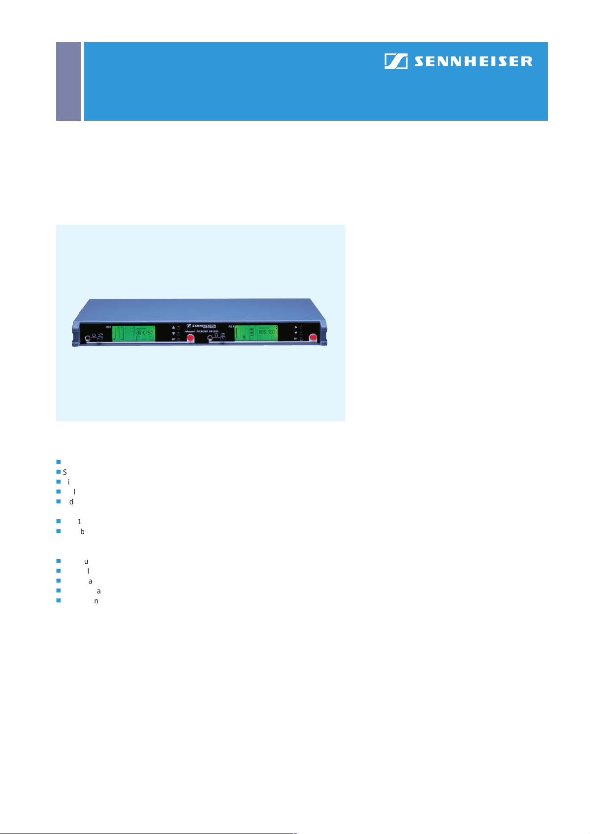
The EM 3032 consists of two complete true diversity receivers in a single 19” 1 U rack
housing. 32 programmable receiving frequencies per receiver ensure flexible channel selection and make this receiver an ideal choice for OB applications or for use in
shows.
General Features
j
Up to 32 programmable receiving frequencies per receiver
j
Switching bandwidth max. 24 MHz (UHF) or 7 MHz (VHF)
j
HiDyn plus™ noise reduction system with 117 dB(A)
j
Multi-function LC display panel
j
Indication of transmitter battery status (only with Sennheiser
transmitters transmitting battery status information)
j
19” 1 U metal housing with built-in mains power supply unit
j
Suitable for multi-channel applications
EM 3032
j
Two true diversity receivers, 19” 1 U housing
j
Integral antenna splitter, 2 x 1 : 2
j
LC display for frequency, RF and AF level
j
Two separate headphone outputs
j
Delivery includes: 1 EM 3032 receiver, 2 telescopic antennas
1 mains cable, 19” rack mount ears
signal-to-noise ratio
rms
EM 3032-U Cat. No. 009264
EM 3032-V Cat. No. 009290
Technical Data EM 3032-U
Type of receiver ..................................Two 32-channel RX
Receiving frequencies .............................................max. 32
Frequency range ........................................... 450–960 MHz
Switching bandwidth.............................................. 24 MHz
Modul ation...................................................... wideband FM
Nominal/peak deviation ................ ± 40 kHz / ± 56 kHz
RF squelch ....................................... 0–100 µV, adjustab le
Signal-to-noise ratio .................................. > 117 dB(A)
Noise reduction system ................................. HiDyn plus™
AF frequency response............... 45–20,000 Hz (–3 dB)
THD (1 kHz) ........................................≤ 0.4 % (typ. 0.2 %)
RF inputs.............................................. 2 BNC sockets, 50 Ω
AF output voltage,
balanced XLR:.............................max. 18 dBU, adjustab le
Headph one output.................... max. 12 dBU, adjustab le
Output impedance..................................................... ≥ 50 Ω
Power supply ...............115 / 230 V AC (+10 % / –15 %)
Housing .......................................................................19“, 1 U
Dimensions .......................................... 436 x 43 x 215 mm
Weight................................................................ approx. 4 kg
In compliance with ......................................... ETS 300 422
Technical Data EM 3031-V
Type of receiver ..................................Two 32-channel RX
Receiving frequencies .............................................max. 32
Frequency range ...........................................138–250 MHz
Switching bandwidth.................................................7 MHz
Modul ation...................................................... wideband FM
Nominal/peak deviation ................ ± 40 kHz / ± 56 kHz
RF squelch ....................................... 0–100 µV, adjustab le
Signal-to-noise ratio .................................. > 117 dB(A)
Noise reduction system ................................. HiDyn plus™
AF frequency response............... 45–20,000 Hz (–3 dB)
THD (1 kHz) ........................................≤ 0.4 % (typ. 0.2 %)
RF inputs.............................................. 2 BNC sockets, 50 Ω
AF output voltage,
balanced XLR:.............................max. 18 dBU, adjustab le
Headph one output.................... max. 12 dBU, adjustab le
Output impedance..................................................... ≥ 50 Ω
Power supply ...............115 / 230 V AC (+10 % / –15 %)
Housing .......................................................................19“, 1 U
Dimensions .......................................... 436 x 43 x 215 mm
Weight................................................................ approx. 4 kg
In compliance with ......................................... ETS 300 422
rms
rms
Page 2
EM 3031/EM 3032
RF Wireless Systems | 3000 Series Receivers
Th e EM 3031 and EM 3032 receivers are fitted wit h an adjustabl e RF sq ue lch, which
mutes the audio output when the antenna voltage drops below the chosen threshol d. The sq uelch can be adjusted between 0 and approx. 100 µV. Wh en the s quel ch
has been triggered, the “MUTE” warning will light up on the receiver display. The
receivers are additionally equipped with an AMF advanced muting function.
This muting function is triggered when the RF signal suddenly drops by approx.
50 dB. The receiver will then be muted for about 3 seconds to avoid the annoying
crackling noise which is caused when a transmitter is switched off.
The EM 3031 and EM 3032 receivers have a headphone output for monitoring the
Mounting the telescopic antennas
incoming audio signal; the monitoring signal is mono. Sennheiser’s closed HD 25
headphones are an ideal choice for monitoring purposes. In order to enable monitor ing even in unfavourable conditions (e.g. low AF signal level from t he transmitter)
and with high ambient noise (on the stage, for example), the signal from the
headphone output is up to 30 dB louder than the LINE output signal. However, this
may lead to distortion if the level of the incoming signal is quite high and if the
volume control is turned up. In this case, turn back the volume until the distortion
disappears. If the sound remains distorted, the transmitter itself is overmodulated.
The Sennheiser transmitter range incl udes many model s which transmit battery
status information. The EM 3031 and EM 3032 receivers are able to receive this
status information. They display the remaining battery or accupack capacity of the
transmitter in %. When the battery is going flat and the remaining capacity lasts for
only 20 to 30 minutes of operation, the “LOW BATT” warning on the display starts
flashing. You should immediately replace the transmitter battery.
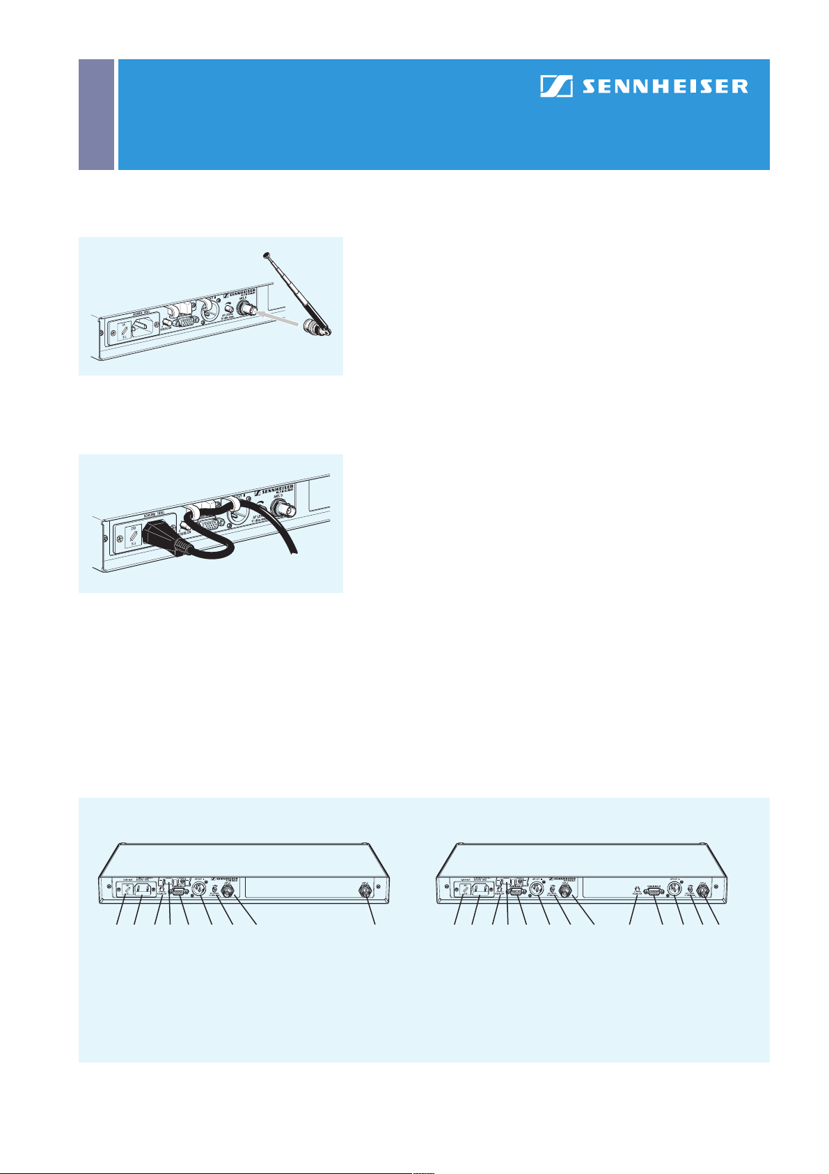
Using the cable grip for the mains cab le
EM 3031 EM 3032
7 8 9 1110 12 13 14 15 7 8 9 1110 12 13 14 159 11 12 13
7 Fuse holder and mains voltage selector
8 Mains connector
9 Squelch control
10 Cable grip
11 Service interface (not used during normal operation)
12 Bal anced XLR-3 audio output
13 AF level control for audio output
14 Antenna socket B
15 A ntenna sock et A
Operating controls of the EM 3031 and EM 3032 – back panel
Page 3

EM 3031/EM 3032
RF Wireless Systems | 3000 Series Receivers
1 3
2
8 9 104 5 6 7
1 “ FREQUENCY MHz” disp lay
2 “CHANNEL” display
3 Alphanumeric main display
4 10-step level display for incoming RF signal,
with peak warning
5 10-step level display for incoming AF signal,
with peak warning
6 6-step display for transmitter battery status,
with “Low Batt” warning
7 Diversity antenna A active
8 Squelch active (MUTE)
9 Diversity antenna B active
10 Frequency groups displ ay
Reading off the LC display
EM 3031 and EM 3032
With the EM 3031 single receiver and EM 3032 twin receiver, Sennheiser offers
two 19” high-quality RF receivers which have excellent operational reliability
and are extremel y user-friendl y. Combined with a suitabl e hand-held or bodypack
transmitter, they form a studio-qua lity radio link. Both receivers use true diversity
technology to reduce drop outs to an absolute minimum and ensure interferencefree operation.
Due to the wide switching bandwidth of the EM 3031 and EM 3032 receivers (24 MHz
for the UHF variant, 7 MHz for VHF) and due to their up to 32 receiving frequencies
you can easil y switch to unused frequencies in case of interference on a selected
channel. The EM 3031 and EM 3032 receivers have been designed for demanding
show and broadcasting applications and are ideally suited for large multi-channel
systems.
With the GA 3030 AM antenna mount, the antenna sockets can be relocated at the
receiver front, for example if the rear of the rack is closed. If you need to choose
an antenna position away from the receivers, Sennheiser offers the A 12 AD UHF
active directional antenna or the A 1031-U passive omni-directiona l antenna for the
UHF range and the A 2 P passive omni-directional antenna for the VHF range. The
EM 3031 and 3032 receivers output the audio signal via an XLR-3 socket at the
rear. The level control serves to adjust the AF signal level and adapt it to the subsequent mixing console or amplifier.
The receiver display indicates the chosen receiving frequency or, optionally,
the channel number which it has been assigned. You can also read off the field
strength of the incoming RF signal in µV and the deviation of the audio signal (i.e.
the modulation level of the RF signal) in %. Both RF and AF display have a peak
warning in case the signal strength becomes excessively high. Short peak periods
are not critical. If, however, the audio signal is overmodulated very often and for
quite some time, the sensitivity of the transmitter must be reduced. The AF display
is additionall y provided with a “peak- ho ld” function, i.e. peak val ues are displayed
for some time so that it becomes easier to detect them.
EM 3031 EM 3032
1 2 3 4 5 6 1 2 3 4 5 6 1 2 3 4 5 6
1 1/4” hea dp hone output jack socket
2 Volume control for headphone output
3 Multi-function LC display
Operating controls of the EM 3031 and EM 3032 – front panel
4 m and . buttons for selecting the receiving
frequency/channel number
5 SET button for menu selection and storage
6 On /off switch
Page 4

EM 3031/EM 3032
RF Wireless Systems | 3000 Series Receivers
215 mm
43 mm
EM 3031 / EM 3032 dimensions
436 mm
Accessories for EM 3031 and EM 3032
j
GA 3030 AM antenna mount Cat. No. 004368
j
A 12 AD UHF active directional antenna (for -U) Cat. No. 004156
j
A 1031-U passive omni-directional antenna (for -U) Cat. No. 004645
j
A 2 P passive omni-directional antenna (for -V) Cat. No. 003533
j
GZA 1036-9 ground plane antenna Cat. No. 002336
j
GZA 1036-TV ground plane antenna (for -U) Cat. No. 002243
j
N/BNC adaptor Cat. No. 033839
j
RG 58 co-axial antenna cable
GZL 1019 A1 (1 m) Cat. No. 002324
GZL 1019 A5 (5 m) Cat. No. 002325
GZL 1019 A10 (10 m) Cat. No. 002326
j
GZV 1019A BNC coupler Cat. No. 002368
j
AS-X custom-built active antenna splitter on request
j
ASA 3000-EU active antenna splitter Cat. No. 009423
j
ASA 3000-UK Cat. No. 008408
j
ASA 3000-US Cat. No. 009407
 Loading...