

Page 1
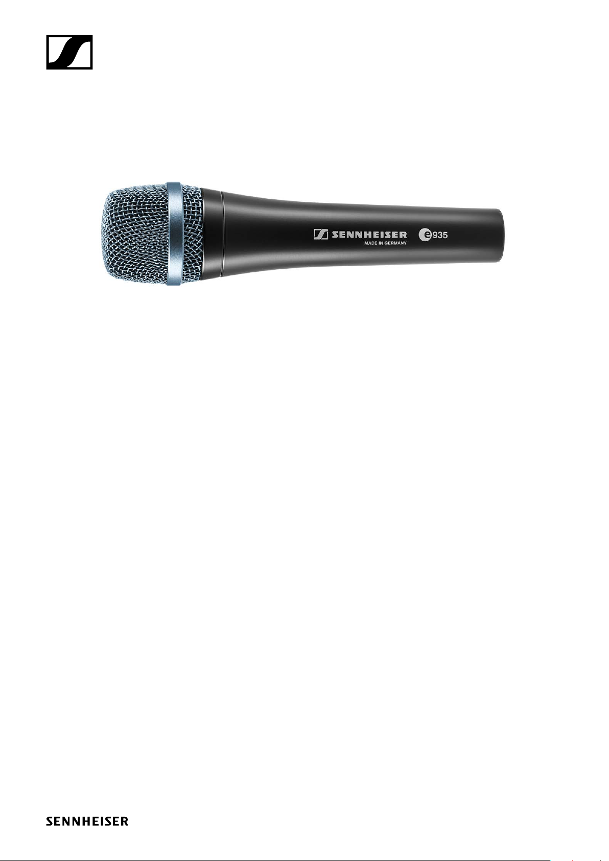
e 935
Instruction manual
Page 2
Delivery includes
• e 935
• MZQ 800 microphone clamp
• pouch
• quick guide
• safety guide
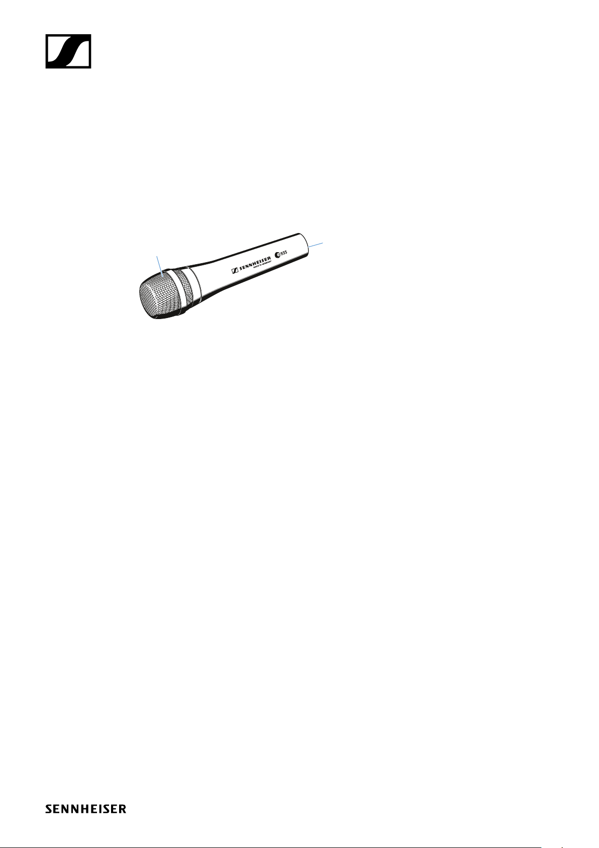
Product overview
Delivery includes
1
1. Sound inlet basket
2. XLR-3 connector
2
e 935 | 2/8
Page 3
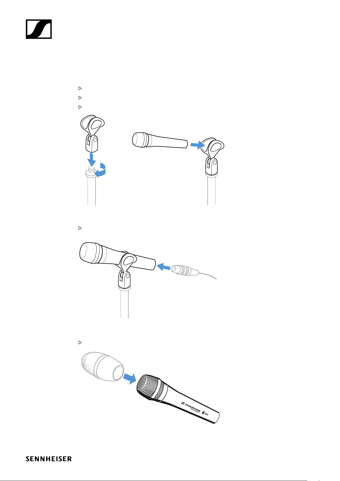
Installation
Attaching the microphone
Screw the microphone clamp to a stand.
Place the microphone with its back end into the microphone clamp.
Orient the microphone together with the microphone clamp.
Installation
Connecting the microphone
Connect the XLR-3 socket of the microphone cable (optional accessories) to the XLR-3 socket of
the microphone.
Using the windshield
Place the MZW 4032 (optional accessories) windshield over the microphone head.
e 935 | 3/8
Page 4

Operation
Operation
Holding the microphone
If you cover the microphone head during transmission, this will change the pick-up pattern of the
microphone and consequently the sound.
Only hold the microphone by its body.
Positioning the microphone
It is vital to observe the following notes:
Position Resulting sound Commentary
A High proximity effect (large bass boost)
Powerful, direct sound
B Less proximity effect (less bass boost)
Some room ambience, natural, balanced sound
C Very little proximity effect (minimal bass boost)
More room ambience, indirect sound
Very little crosstalk from other
sound sources
More crosstalk from other
sound sources
Higher crosstalk from other
sound sources
CBA
5-10 cm
If sibilance occurs:
Position the microphone slightly to the side and not directly in front of the mouth.
>10 cm
e 935 | 4/8
Page 5

Operation
Positioning the monitor loudspeakers
To prevent feedback and crosstalk, postion your monitor loudspeakers in the angle area of the
highest cancellation of the microphone (approx. 180°).
180°
e 935 | 5/8
Page 6

Cleaning and maintaining the e 935
Cleaning and maintaining the e 935
CAUTION
LIQUIDS CAN DAMAGE THE ELECTRONICS OF THE PRODUCT!
Liquids entering the housing of the product can cause a short-circuit and damage the electronics.
Keep all liquids away from the product.
Do not use any solvents or cleansing agents.
Disconnect the products from the power supply system and remove rechargeable batteries and
batteries before you begin cleaning.
Clean all products only with a soft, dry cloth.
Cleaning the sound inlet basket of the microphone module
Unscrew the sound inlet basket.
Remove the foam insert from the sound inlet basket.
Use a slightly damp cloth to clean the sound inlet basket from the inside and ouside.
If necessary, clean the foam insert with a mild detergent or replace the foam insert.
Dry the foam insert.
Reinsert the foam insert.
Replace the sound inlet basket on the microphone head and screw it tight.
e 935 | 6/8
Page 7

Specifications
Transducer principle dynamic
Frequency response 40 - 18,000 Hz
Pick-up pattern cardioid
Sensitivity (free field, no load) 2.8 mV/Pa
Nominal impedance (at 1 kHz) 350 Ω
Min. terminating impedance 1 kΩ
Connector XLR-3
Temperature range 0 °C to +40 °C
Dimensions ⌀ 47 x 151 mm
Weight 355 g
Polar pattern
0°
0°
10
15
20
25
dB
0
5
30°
60°
120°
90°
125 Hz
250 Hz
500 Hz
1,000 Hz
2,000 Hz
4,000 Hz
8,000 Hz
16,000 Hz
30°
60°
90°
120°
Specifications
150°
180°
Frequency response
dBV
-40
-50
-60
-70
-80
-90
50
100
200
0°, 1 m
180°
500
150°
1,000
2,000
5,000
10,000
20,000
Hz
e 935 | 7/8
Page 8

Connector assignment
••
••
••
••
••
••
• •• ••
Overview of applications
e 602 II
+ +
1
2
3
XLR
+
2
1
3
XLR
+
2
1
3
XLR 6.3 mm
XLR
6.3 mm
12
3
+
+
+
UNBALANCED
BALANCED
Overview of applications
Primary application
Secondary application
•••• •
+
12
3
XLR
e 604
e 608
e 609
e 614
e 835
e 845
e 865
e 901
e 902
e 904
e 906
e 908
e 914
• •••
• ••
silver
• • ••• •
•• • •• • • •
•• •
•• •
•• •
• • •
•• •
• •••
• • ••• •
••• •
• • • •• • • •
e 935
e 945
e 965
• •
• •
e 935 | 8/8
 Loading...