

Page 1
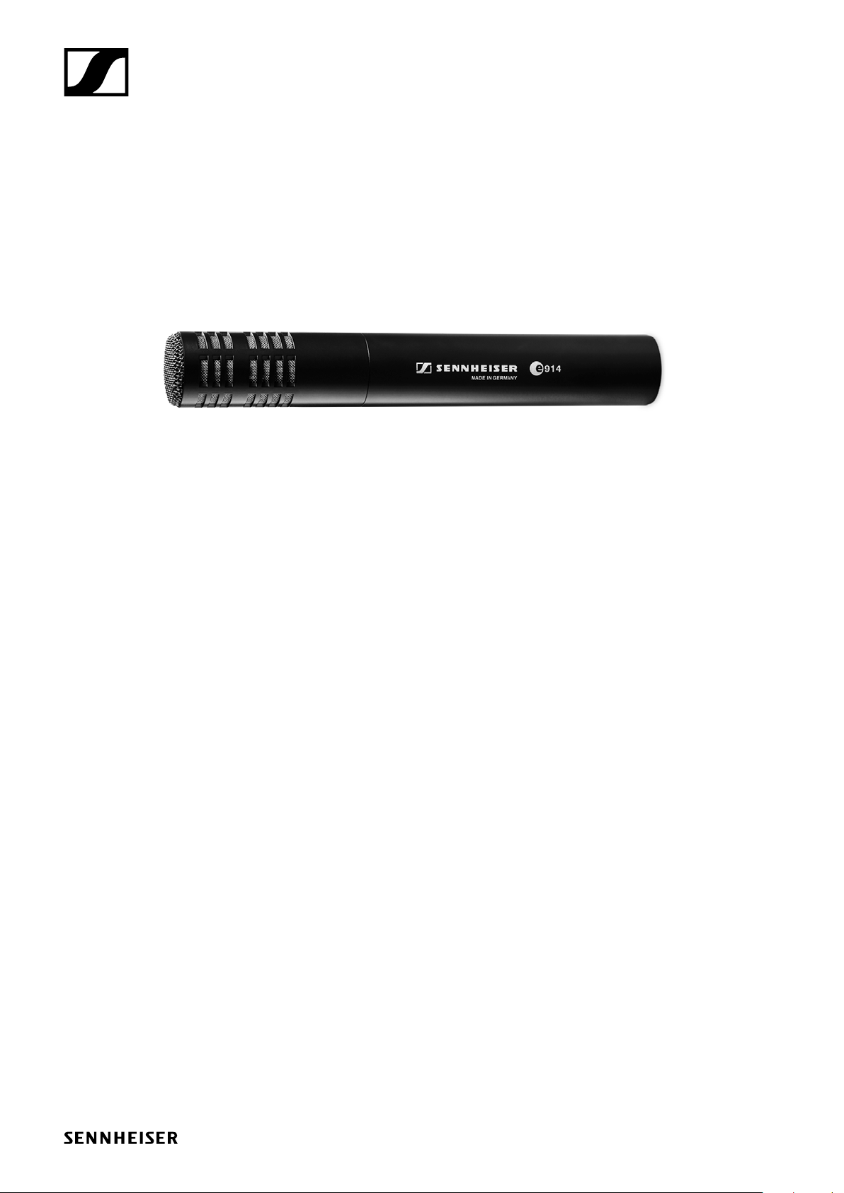
e 914
Instruction manual
Page 2
Delivery includes
• e 914
• MZQ 800 microphone clamp
• MZW 64 windshield
• pouch
• quick guide
• safety guide
The microphone head is not compatible with the K6 powering module.
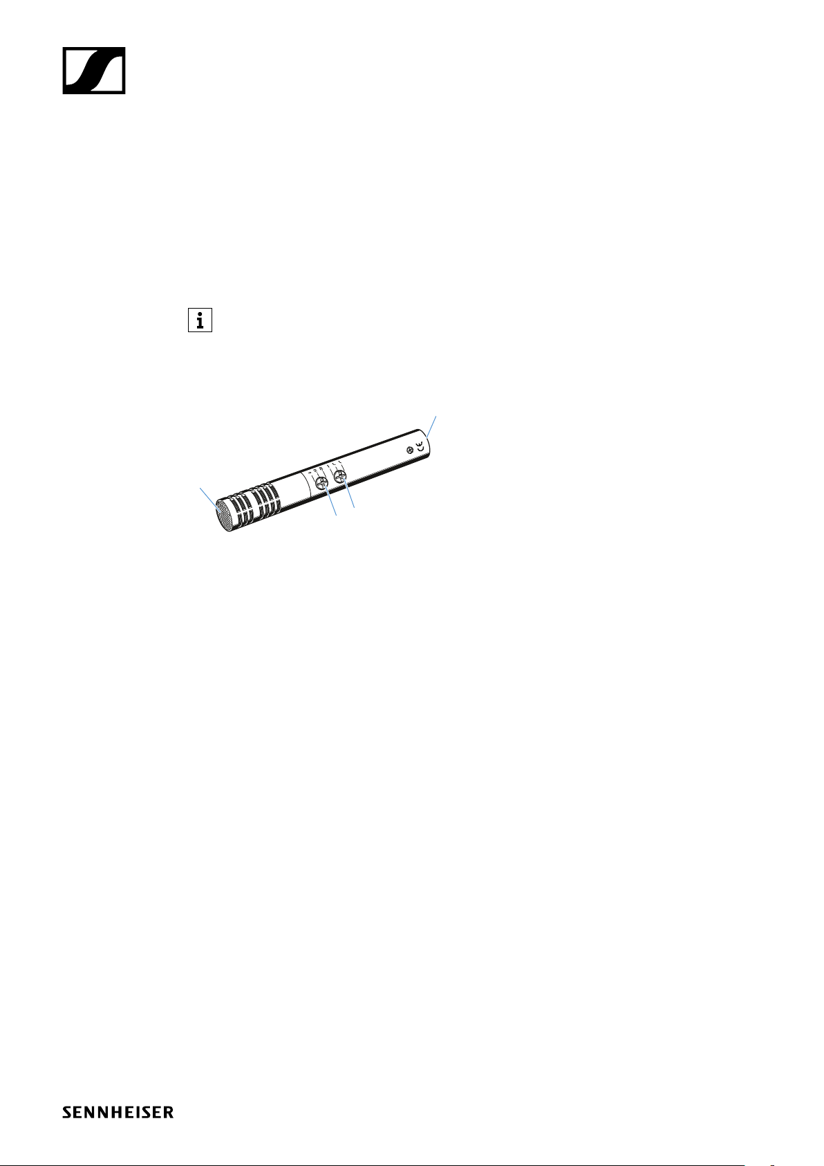
Product overview
2
Delivery includes
1
3
1. Sound inlet basket
2. XLR-3 connector
3. Adjusting the sensitivity
4. Adjusting the bass filter
4
e 914 | 2/8
Page 3

Installation
Attaching the microphone
Screw the microphone clamp to a stand.
Place the microphone with its back end into the microphone clamp.
Orient the microphone together with the microphone clamp.
Installation
Connecting the microphone
Connect the XLR-3 socket of the microphone cable (optional accessories) to the XLR-3 socket of
the microphone.
Using the windshield
Place the MZW 64 (optional accessories) windshield over the microphone head.
e 914 | 3/8
Page 4

Operation
Operation
Positioning the microphone: Drums / Percussions
Attention: When closing the hi-hat, a strong air current is created on the edge. If the microphone is
positioned too close to the edge, interfering noise due to the air current can occur.
It is vital to observe the following notes:
Pos. Commentary
A Position the microphone a few centimetres above the outer edge of the hi-hat
aiming down. If necessary, remove unwanted low-frequency signal portions by high
pass filtering.
B Good starting position for live miking applications. If the overhead microphones are
only used for picking up the cymbals, unwanted signal portions can be attenuated
by high pass filtering.
A B
In order to prevent interference due to crosstalk between adjacent sound sources, try to position
the microphone so that the interfering sound source is located in the angle area of the highest cancellation of the microphone (approx. 180°, see polar diagram).
Positioning the monitor loudspeakers
To prevent feedback and crosstalk, postion your monitor loudspeakers in the angle area of the
highest cancellation of the microphone (approx. 180°).
180°
e 914 | 4/8
Page 5

Operation
Sensitivity and bass filter
The e 914 is equipped with a three-position sensitivity switch and a bass filter switch.
Adjusting the sensitivity
The microphone sensitvity can remain unchanged (0) or be reduced by 10 dB or 20 dB. The latter is
recommended when there is a risk that the microphone or subsequent microphone input is overmodulated, e.g. due to high sound pressure levels from drums, brass instruments, etc.
We recommend that you mute the corresponding microphone channel on the mixing console
before connecting and disconnecting the microphone cable, switching on and off the phantom
powering or setting the switches (see figure above).
0 dB
-10 dB
-20 dB
Adjusting the bass filter
The e 914 has been designed for an extended low-frequency bass response. With certain live or
close instrument miking applications, an over-emphasis of the low frequencies can occur. This can
be compensated for by the 6 dB/octave roll-off filter. The cut-off filter reduces low-frequency wind
noise by 18 dB/octave.
flat
cut off
roll off
e 914 | 5/8
Page 6

Cleaning and maintaining the e 914
Cleaning and maintaining the e 914
CAUTION
LIQUIDS CAN DAMAGE THE ELECTRONICS OF THE PRODUCT!
Liquids entering the housing of the product can cause a short-circuit and damage the electronics.
Keep all liquids away from the product.
Do not use any solvents or cleansing agents.
Disconnect the products from the power supply system and remove rechargeable batteries and
batteries before you begin cleaning.
Clean all products only with a soft, dry cloth.
e 914 | 6/8
Page 7

Specifications
Specifications
Transducer principle pre-polarised condenser microphone
Frequency response 20 - 20,000 Hz
Pick-up pattern cardioid
Sensitivity (free field, no load)
with pre-attenuation
Nominal impedance (at 1 kHz) 100 Ω
Min. terminating impedance 1 kΩ
Max. sound pressure level (at 1 kHz) 137/147/157 dB SPL (depending on pre-attenua-
Equivalent noise level
A-weighted (DIN IEC 651)
CCIR-weighted (CCIR 468-3)
Pre-attenuation 0 dB, -10 dB, -20 dB
Bass filter linear
Phantom powering 48 V / 2.2 mA
Connector XLR-3
Dimensions ⌀ 24 x 157 mm
Weight 198 g
7 mV/Pa
2.3 mV/Pa / 0.7 mV/Pa
tion)
19 dB
30 dB
roll-off 130 Hz, 6 dB/oct.
cut-off 85 Hz, 18 dB/oct.
Polar pattern
30°
60°
90°
120°
150°
0°
10
15
20
25
dB
180°
Frequency response
dB
0
- 10
- 20
0°
0
5
180°
30°
150°
60°
120°
90°
125 Hz
250 Hz
500 Hz
1,000 Hz
2,000 Hz
4,000 Hz
8,000 Hz
16,000 Hz
50
100
200
flat roll off
500
1,000
2,000
5,000
10,000
20,000
cut off
Hz
e 914 | 7/8
Page 8

Connector assignment
••
••
••
••
••
••
• •• ••
Overview of applications
e 602 II
e 604
e 608
+ +
1
2
3
XLR
+
2
1
3
XLR
3
XLR
6.3 mm
12
+
+
BALANCED
Overview of applications
Primary application
Secondary application
•••• •
• •••
• ••
+
12
3
XLR
e 609
e 614
e 835
e 845
e 865
e 901
e 902
e 904
e 906
e 908
e 914
e 935
e 945
silver
• • ••• •
•• • •• • • •
•• •
•• •
•• •
• • •
•• •
• •••
• • ••• •
••• •
• • • •• • • •
• •
• •
e 965
e 914 | 8/8
 Loading...