

Page 1
AVX
System Manual
Page 2

2 | evolution wireless Digital 1
Page 3
Contents
Important safety information . . . . . . . . . . . . . . . . . . . . . . . . . . . . . . . . . . . . . . . 2
AVX – perfect sound you can rely on . . . . . . . . . . . . . . . . . . . . . . . . . . . . . . . . . 5
Package contents . . . . . . . . . . . . . . . . . . . . . . . . . . . . . . . . . . . . . . . . . . . . . . . . . . 6
Product overviews . . . . . . . . . . . . . . . . . . . . . . . . . . . . . . . . . . . . . . . . . . . . . . . . . . 7
EKP AVX receiver . . . . . . . . . . . . . . . . . . . . . . . . . . . . . . . . . . . . . . . . . . . . . . . . . . . . 7
SKM AVX, SKM AVX-S and SK AVX transmitters . . . . . . . . . . . . . . . . . . . . . . . . . 9
USB power supply/charger . . . . . . . . . . . . . . . . . . . . . . . . . . . . . . . . . . . . . . . . . . 12
ME 2 clip-on microphone . . . . . . . . . . . . . . . . . . . . . . . . . . . . . . . . . . . . . . . . . . . 12
MKE 2 clip-on microphone . . . . . . . . . . . . . . . . . . . . . . . . . . . . . . . . . . . . . . . . . . 12
Putting the products into operation . . . . . . . . . . . . . . . . . . . . . . . . . . . . . . . . . 13
Putting the receiver into operation . . . . . . . . . . . . . . . . . . . . . . . . . . . . . . . . . . 14
Putting the bodypack transmitter into operation . . . . . . . . . . . . . . . . . . . . . . 15
Putting the clip-on microphones into operation . . . . . . . . . . . . . . . . . . . . . . . 16
Putting the handheld transmitter into operation . . . . . . . . . . . . . . . . . . . . . . 20
Recharging the accupack . . . . . . . . . . . . . . . . . . . . . . . . . . . . . . . . . . . . . . . . . . . 21
Using the products . . . . . . . . . . . . . . . . . . . . . . . . . . . . . . . . . . . . . . . . . . . . . . . . 23
Switching the devices on or off . . . . . . . . . . . . . . . . . . . . . . . . . . . . . . . . . . . . . . 23
Checking the charge status of the accupacks . . . . . . . . . . . . . . . . . . . . . . . . . . 24
Checking the RF signal level . . . . . . . . . . . . . . . . . . . . . . . . . . . . . . . . . . . . . . . . . 25
Muting the bodypack transmitter or
the SKM AVX-S handheld transmitter . . . . . . . . . . . . . . . . . . . . . . . . . . . . . . . . 25
Pairing a receiver with a transmitter . . . . . . . . . . . . . . . . . . . . . . . . . . . . . . . . . 26
Identifying paired devices . . . . . . . . . . . . . . . . . . . . . . . . . . . . . . . . . . . . . . . . . . 26
Displaying or adjusting the receiver‘s audio output level . . . . . . . . . . . . . . . 27
Cleaning and maintaining the products . . . . . . . . . . . . . . . . . . . . . . . . . . . . . . 28
If a problem occurs ... . . . . . . . . . . . . . . . . . . . . . . . . . . . . . . . . . . . . . . . . . . . . . . 29
Specifications . . . . . . . . . . . . . . . . . . . . . . . . . . . . . . . . . . . . . . . . . . . . . . . . . . . . . 30
Licenses . . . . . . . . . . . . . . . . . . . . . . . . . . . . . . . . . . . . . . . . . . . . . . . . . . . . . . . . . . 34
Accessories . . . . . . . . . . . . . . . . . . . . . . . . . . . . . . . . . . . . . . . . . . . . . . . . . . . . . . . 36
Manufacturer Declarations . . . . . . . . . . . . . . . . . . . . . . . . . . . . . . . . . . . . . . . . . 37
AVX 1
Page 4

Important safety information
Important safety information
1. Read these safety instructions and the instruction manuals of the products.
2. Keep these safety instructions and the instruction manuals of the products. Always include these safety instructions and the instruction manuals
when passing the products on to third parties.
3. Heed all warnings.
4. Follow all instructions.
5. Do not use the products near water.
6. Do not operate near any heat sources such as radiators, stoves, or other
apparatus (including amplifiers) that produce heat.
7. Only operate the products from the types of power source specified in the
chapter “Specifications” on page 30 and indicated on the power supply
unit.
8. Unplug the power supply units from the wall socket,
- to completely disconnect the products from the power supply system,
- during lightning storms or
- when not using the products for long periods of time.
9. Always ensure that the power supply units are
- in a safe operating condition and easily accessible,
- properly plugged into the wall socket,
- only operated within the permissible temperature range,
- not covered or exposed to direct sunlight for longer periods of time in
order to prevent heat accumulation.
10. Protect the power cords from being walked on or pinched, particularly at
the points where they exit from wall sockets, power supply units and products.
11. Only use attachments, accessories or spare parts specified by Sennheiser
12. Refer all servicing to qualified service personnel. Servicing is required
when the products have been damaged in any way, liquid has been spilled
or objects have fallen into the products, when the products has been
exposed to rain or moisture, do not operate normally, or have been
dropped.
13. WARNING: To reduce the risk of fire or electric shock, do not expose the
products to rain or moisture.
14. Do not expose the products to dripping or splashing. Ensure that no
objects filled with liquids, such as vases, are placed on the products.
2 AVX
Page 5
Important safety information
Safety instructions for lithium-ion rechargeable batteries
If abused or misused, the rechargeable batteries may leak. In extreme cases,
they may even present a risk of
•explosion,
• fire development,
• heat generation,
•smoke or gas development.
Sennheiser does not accept any liability for damage arising from abuse or misuse.
왘 Keep away from children.
왘 Only charge rechargeable batteries with chargers recommended by
Sennheiser.
왘 Observe correct polarity.
왘 Pack/store charged rechargeable batteries so that the terminals cannot
contact each other – danger of shorting out/fire hazard.
왘 Do not expose to moisture.
왘 Switch rechargeable battery-powered products off after use.
왘 Only charge rechargeable batteries at ambient temperatures between
10 °C/50 °F and 40 °C/104 °F.
왘 When not using rechargeable batteries for extended periods of time,
charge them regularly (about every three months).
왘 Do not mutilate or dismantle.
왘 Do not heat above 60 °C/140 °F, e.g. do not expose to sunlight or throw
into a fire.
왘 Immediately remove rechargeable batteries from obviously defective prod-
ucts.
왘 Do not continue to use defective rechargeable batteries.
왘 Only use rechargeable batteries specified by Sennheiser.
왘 Dispose of rechargeable batteries at special collection points or return them
to your specialist dealer.
왘 Store the products in a cool and dry place at room temperature (approx.
20 °C/68 °F).
왘 Remove the rechargeable batteries if the products will not be used for
extended periods of time.
AVX 3
Page 6

Important safety information
Intended use
The microphones, the transmitters, the receiver and the accessories of the
Sennheiser AVX system can be combined with each other and have been
designed for use in video recordings in dry environments.
In order that speech, music and vocals are transmitted in the best possible
quality, the receiver has to be connected, as described in this instruction manual, to a video camera or a DSLR camera with video recording function.
The products can be used for commercial purposes.
Intended use includes:
• having read and understood these safety instructions and the instruction
manuals of the products
• using the products within the operating conditions and limitations
described in these safety instructions and in the instruction manuals of the
products.
It is considered improper use when the products are used for any application
not named in the instruction manuals of the products.
Sennheiser does not accept liability for damage arising from abuse or misuse
of the products and their accessories.
4 AVX
Page 7

AVX – perfect sound you can rely on
AVX – perfect sound you can rely on
AVX is the wireless digital microphone system for your film projects and is
ideal for use with both video and DSLR cameras.
AVX features self-configuring digital transmission which eliminates time-consuming frequency setup. The ultra compact receiver can be rotated freely
around its XLR connector to avoid obstructing other devices mounted on your
camera. It switches on and off automatically with your camera, thereby saving
battery power. AVX matches perfectly to your camera‘s input sensitivity without having to adjust the audio level on the microphone. From professional
wedding video to documentaries, from street interviews to corporate videos,
AVX just works allowing you to concentrate on creativity.
• Very fast setup
• Receiver plugs directly into the XLR audio input of the camera
• Ultra compact receiver
• Receiver switches on and off with the camera‘s P48 phantom power
• Optimized dynamic range
• Automatic frequency management
• AES 256 encryption
• License-free 1.9 GHz frequency range
• DSLR accessories included
•Metal housing
• Made in Germany
AVX 5
Page 8

Package contents
Package contents
Package contents
EKP AVX receiver 1 1 1 1
SK AVX bodypack transmitter 1 1 – 1
ME 2 clip-on microphone 1 – – 1
MKE 2 clip-on microphone – 1 – –
SKM AVX-S handheld transmitter
with mute switch
incl. MMD 835-1 microphone head
(cardioid)
SKM AVX handheld transmitter
without mute switch
incl. MMD 42-1 microphone head
(omni-directional)
BA 10 accupack – – 1 1
BA 20 accupack 1 1 1 1
BA 30 accupack 1 1 – 1
EKP AVX adapter 1 1 1 1
Lavalier Set Lavalier Set Pro Handheld Set Combo Set
AVX-ME 2 AVX-MKE 2 AVX-835 AVX-MMD 42-1
– – 1 –
– – – 1
1
NT 5-10U power supply unit 1 1 1 1
CI 400 adapter cable 1 1 1 1
Microphone stand clamp for
handheld transmitter
Bag 1 1 1 1
1
only available in the USA
– – 1 1
6 AVX
Page 9
Product overviews
1
1
2
4
5
6
3
Product overviews
The transmitters and the receiver are available in different country variants:
• Country variant -3 for Europe, the Mid East and Australia
• Country variant -4 for North, Central and South America (except Brazil)
•Country variant -5 for Japan
• Country variant -6 for Taiwan
•Country variant -7 for Brazil
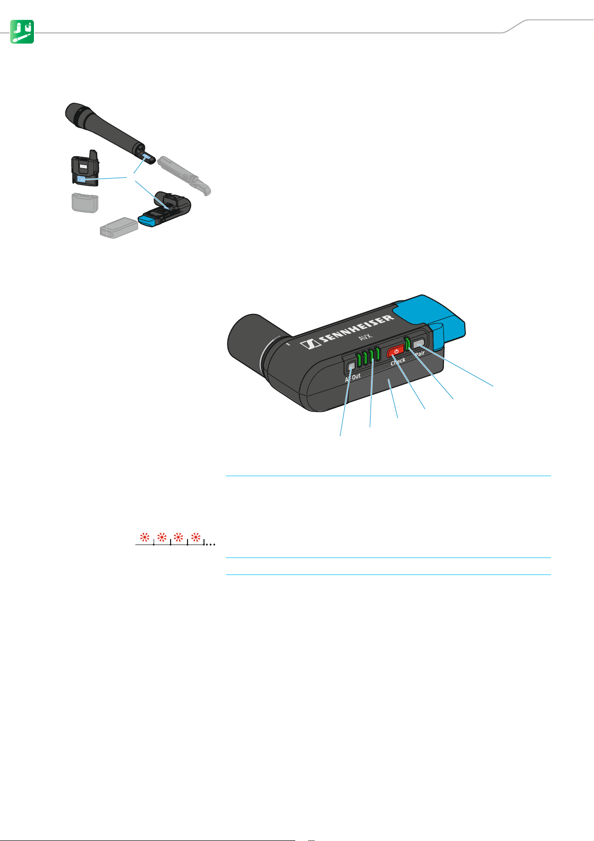
The country variant can be found on the packaging and on the type plate 1
as shown on the left.
왘 Only use the country variant permitted for use at the venue.
왘 Do not combine devices of different country variants.
EKP AVX receiver
1 AF Out button for displaying and adjusting the audio output level (see page 27)
2 4-step LED display When the On/Off/Check button has been pressed, the LED display lights up
green to indicate the remaining battery life of the receiver‘s BA 20 accupack
(see page 24); when the AF Out button has been pressed, the LED display
lights up red to indicate the audio output level (see page 27).
When the right LED flashes red, the capacity of the receiver‘s BA 20 accupack
is only sufficient for a maximum of 15 minutes of operation.
3 BA 20 accupack For details, see page 8.
4 On/Off/Check button Short-press to switch the receiver on (see page 23) or to display the charge
status of the accupack (see page 24);
Long-press to switch the receiver off (see page 23).
AVX 7
Page 10

Product overviews
max. 320°
1
2
5 Status LED
6 Pair button Short-press to identify the paired transmitter (see page 26).
7 Rotatable XLR-3 connector for connection to the video camera or the DSLR camera
lights up green:
flashes green:
flashes alternately
green and red:
lights up yellow:
flashes red:
lights up red:
A radio link to the transmitter is established. The accupack of the received
transmitter is sufficiently charged.
The Pair button has been short-pressed. The paired transmitter is being identified.
The Pair button has been long-pressed. The receiver establishes a radio link to
a transmitter whose Pair button has also been long-pressed.
The received transmitter has been muted with its MUTE switch.
The accupack capacity of the received transmitter is only sufficient for approx.
15 minutes of operation.
No radio link to a transmitter.
Long-press to change the pairing (see page 26).
The receiver can be rotated by a maximum angle of 320°.
8 EKP AVX adapter The EKP AVX adapter consists of a hot shoe adapter and a belt clip.
The belt clip allows the attachment of the receiver to a belt or a pocket (see
page 15).
The hot shoe adapter allows the attachment of the receiver to the hot shoe of
a DSLR camera. The receiver can then be connected to the DSLR camera using
the CI 400 adapter cable (see page 14).
BA 20 accupack for the EKP AVX receiver
1 Charge status LED
2 Micro USB socket for charging the accupack (see page 21)
lights up green: The accupack is fully charged.
lights up red: The accupack is being charged.
8 AVX
Page 11
Product overviews
1
2
3
4
5
6
7
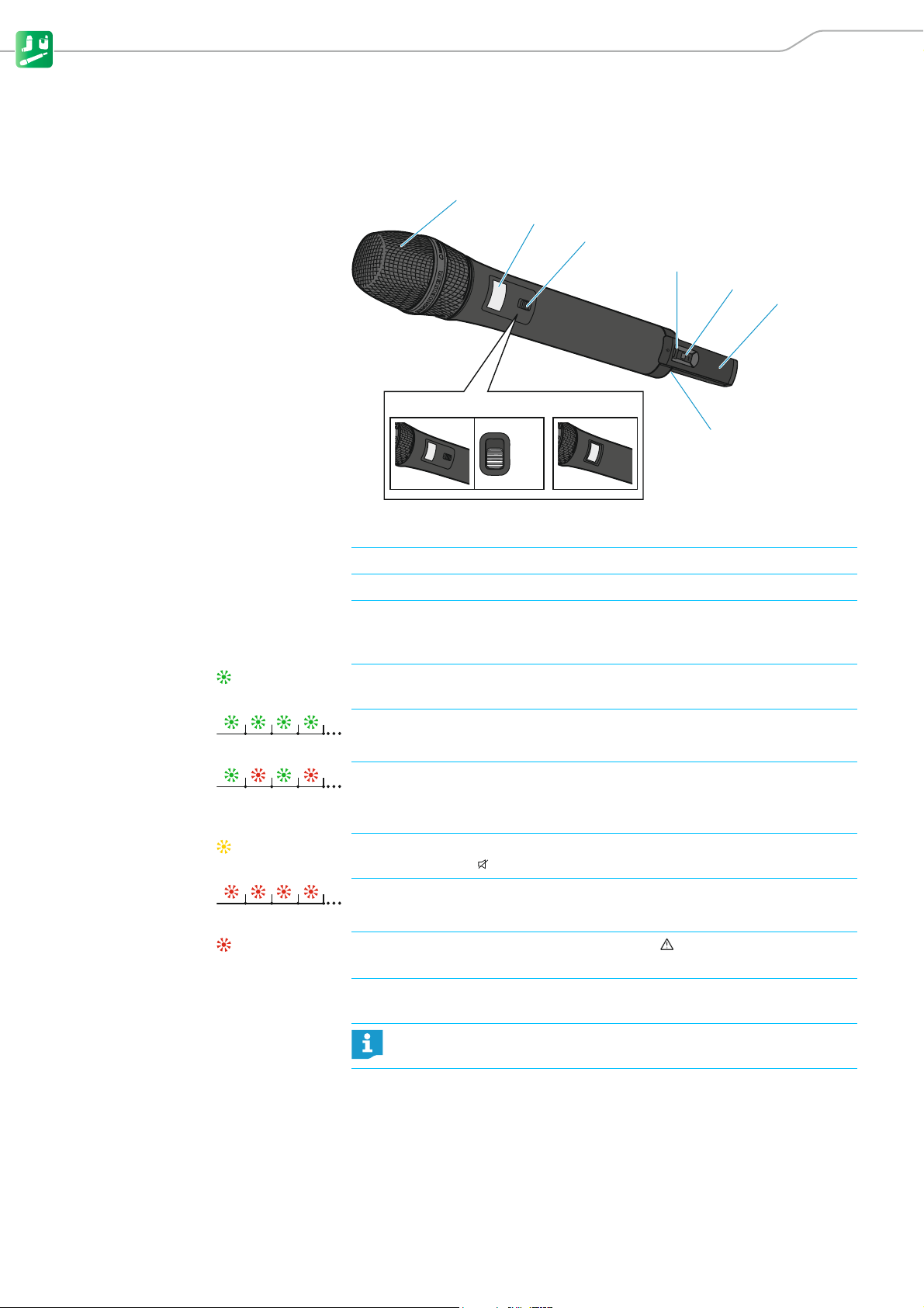
SKM AVX, SKM AVX-S and SK AVX transmitters
SKM AVX and SKM AVX-S handheld transmitters
AVX SKM-S AVX SKM
Mic
Mute
1 Unscrewable microphone head For details, see page 21.
2 Display panel For details, see page 11.
3 MUTE switch for muting the SKM AVX-S handheld transmitter (for details, see page 25)
4 ON/OFF
button
with status LED Slide briefly to switch the handheld transmitter on.
Slide and hold to switch the handheld transmitter off (for details, see
page24).
lights up green:
flashes green:
flashes alternately
green and red:
lights up yellow:
flashes red:
lights up red:
A radio link to the receiver is established. The accupack of the handheld transmitter is sufficiently charged.
The Pair button has been short-pressed. Paired devices are being identified.
The Pair button has been long-pressed. The handheld transmitter establishes
a radio link to a receiver whose Pair button has also been long-pressed.
The SKM AVX-S handheld transmitter has been muted with the MUTE switch.
In addition, Muted is displayed on the display panel.
The accupack capacity of the received transmitter is only sufficient for approx.
15 minutes of operation.
No radio link to a receiver. In addition, No Link is displayed on the display
panel.
5 Pair button Short-press to identify the paired receiver (see page 26).
6 Antenna Do not cover the antenna during transmission to avoid a reduction in
7 BA 10 accupack For details, see page 10.
AVX 9
Long-press to change the pairing (see page 26).
the transmission range.
Page 12
Product overviews
1
3
2
1
2
1
2
3
5
7
7
4
6
8
0
9
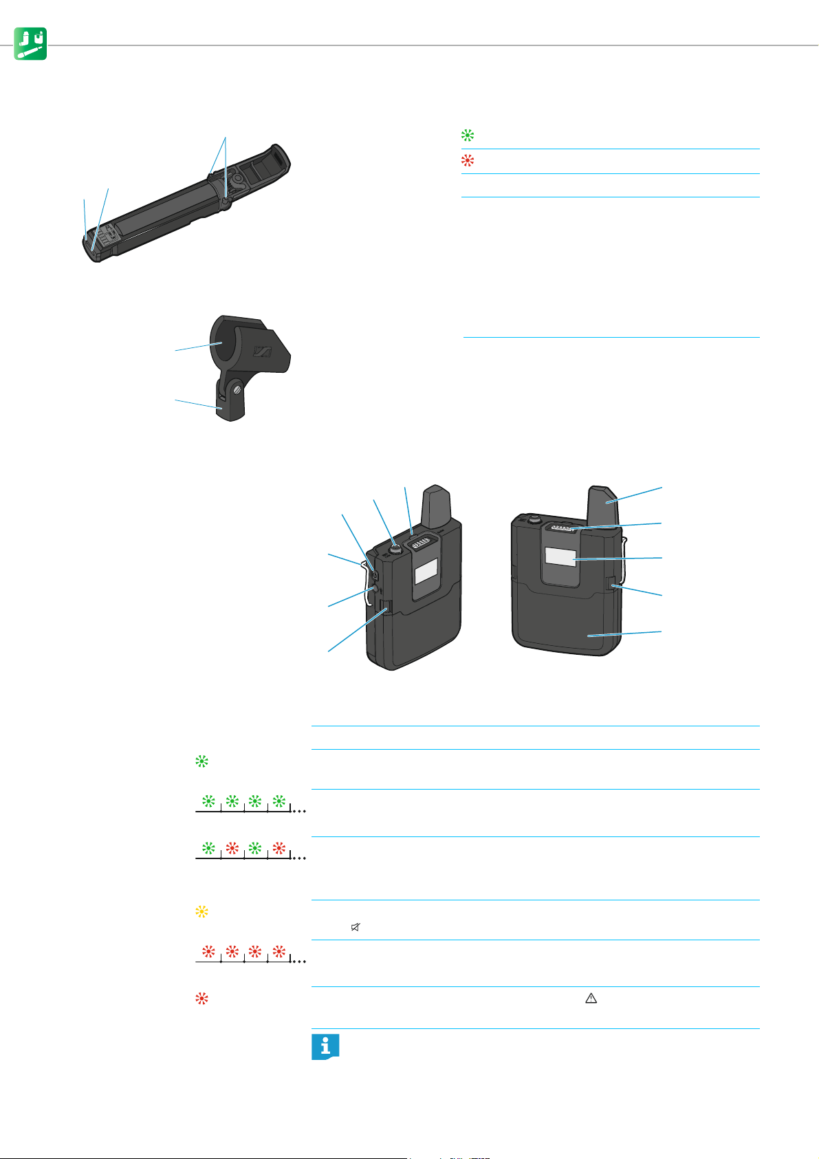
BA 10 accupack for the SKM AVX or SKM AVX-S handheld transmitter
1 Charge status LED
2 Micro USB socket for charging the accupack (see page 21)
3 Catches Press simultaneously to release the accupack from
Microphone stand clamp for the handheld transmitters
1 Microphone clamp for attachment of the handheld transmitter
2 Thread for screwing the microphone clamp onto a stand
SK AVX bodypack transmitter
lights up green: The accupack is fully charged.
lights up red: The accupack is being charged.
the handheld transmitter.
1 On/Off button Short-press to switch the bodypack transmitter on.
Long-press to switch the bodypack transmitter off (for details, see page 24).
2 Mic/Line 3.5 mm jack socket for connecting the clip-on microphone
3 Status LED
4 Antenna Do not cover the antenna during transmission to avoid a reduction in
10 AVX
lights up green:
flashes green:
flashes alternately
green and red:
lights up yellow:
flashes red:
lights up red:
A radio link to the receiver is established. The accupack of the bodypack transmitter is sufficiently charged.
The Pair button has been short-pressed. Paired devices are being identified
(for details, see page 26).
The Pair button has been long-pressed. The bodypack transmitter establishes
a radio link to a receiver whose Pair button has also been long-pressed (for
details, see page 26).
The bodypack transmitter has been muted with its MUTE switch. In addition,
Muted is displayed on the display panel (for details, see page 25).
The accupack capacity of the bodypack transmitter is only sufficient for
approx. 15 minutes of operation.
No radio link to a receiver. In addition, No Link is displayed on the display
panel.
the transmission range.
Page 13
Product overviews
1
2
1
2
3
5 MUTE switch for muting the bodypack transmitter (for details, see page 25)
6 Display panel For details, see page 11.
7 Catches Press simultaneously to release the accupack from the bodypack transmitter.
8 BA 30 accupack For details, see page 11.
9 Pair button Short-press to identify the paired receiver (see page 26).
0 Belt clip For details, see page 15.
Long-press to change the pairing (see page 26).
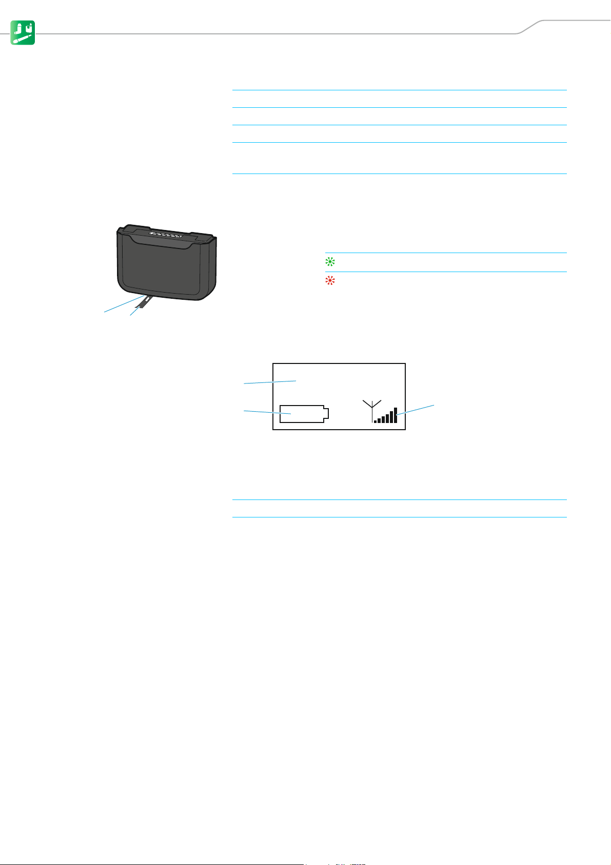
BA 30 accupack for the SK AVX bodypack transmitter
1 USB cover flap Covers the micro USB socket for charging the accupack
(see page 21).
2 Charge status LED
Displays of the transmitters
lights up green: The accupack is fully charged.
lights up red: The accupack is being charged.
AVX 0000
10 h
1 Name of the radio link The name of the radio link always consists of “AVX” and the last four digits of
the serial number of the paired receiver. The receiver‘s serial number can be
found on the type plate under the accupack.
You cannot change this name.
2 Expected battery life of the accupack For details, see page 24.
3 6-segment RF signal level display Displays the field strength of the transmitted signal at the receiver.
AVX 11
Page 14
Product overviews
1
3
2
1
2
3
4
5
1
2
3
4
5
6
7
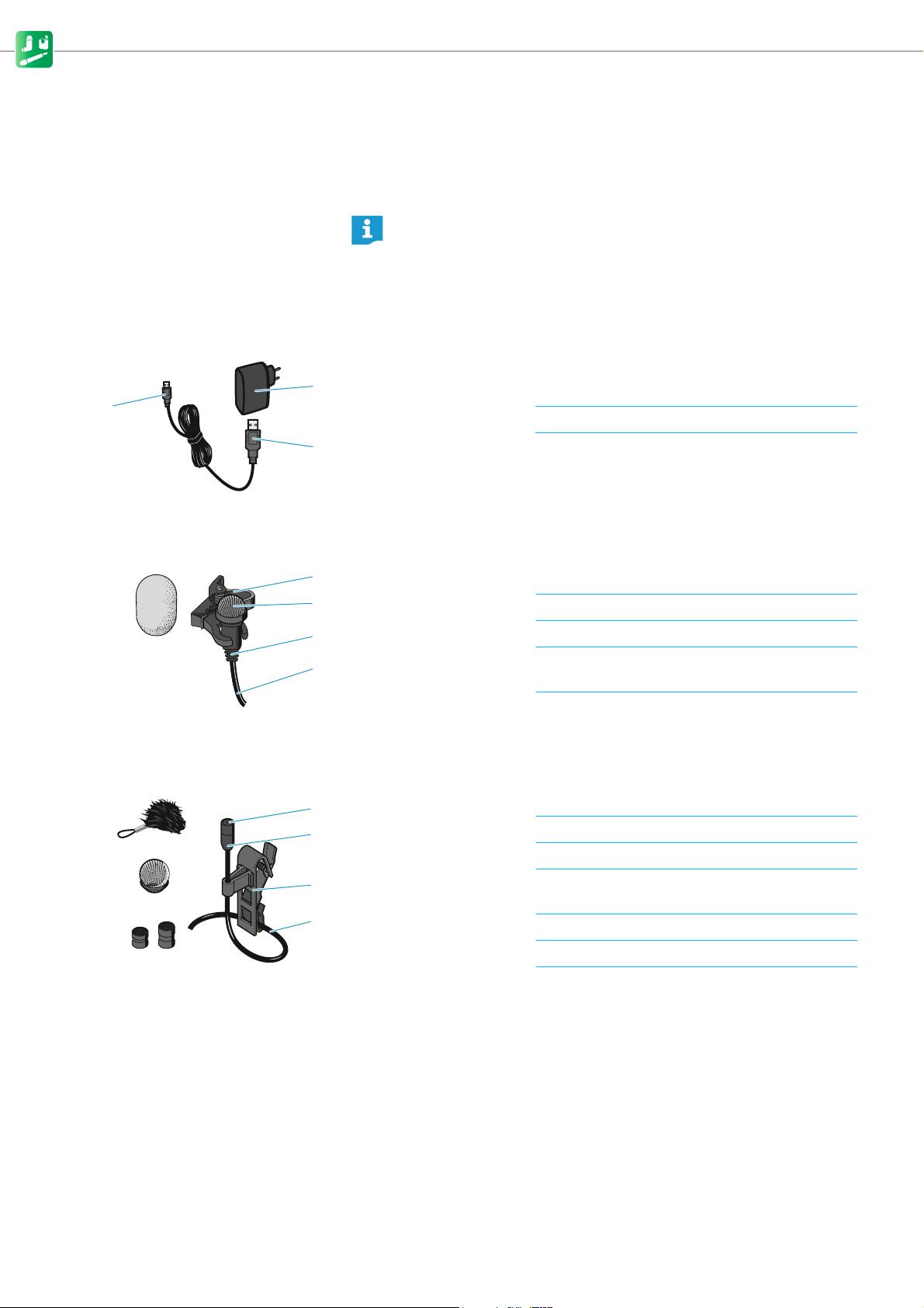
USB power supply/charger
The NT 5-10U power supply/charger is suitable for recharging the BA 10 accupack (handheld transmitter), the BA 20 accupack (receiver) or the BA 30
accupack (bodypack transmitter).
You can recharge the BA 10, BA 20 and BA 30 accupacks as follows:
• using the Sennheiser NT 5-10U USB power supply/charger
•using any USB power supply/charger
• via the USB port of a computer
• via a USB hub with its own power supply
• via a mobile USB power supply (power bank)
1 NT 5-10U USB power supply/charger (country-specific) for
charging the accupacks
2 USB connector (type A) for connection to the USB power supply/charger
3 Micro USB connector for connection to an accupack
ME 2 clip-on microphone
1 Microphone clip for attaching the clip-on microphone to clothing
2 Microphone capsule with omni-directional pick-up pattern
3 Anti-kink protection to prevent cable damage
4 Connection cable (1.6 m) with lockable 3.5 mm jack plug for connection to
the bodypack transmitter
5 Foam windshield for attenuating wind noise by 10 dB
MKE 2 clip-on microphone
1 Microphone capsule with omni-directional pick-up pattern
2 Anti-kink protection to prevent cable damage
3 Microphone clip for attaching the clip-on microphone to clothing
4 Connection cable (1.6 m) with lockable 3.5 mm jack plug for connection to
the bodypack transmitter
5 Frequency response caps for sound optimization
6 Metal windshield for attenuating wind noise by 20 dB
7 Fur windshield for attenuating wind noise by additional 10 dB;
with retaining loop for secure attachment to the
clip-on microphone
12 AVX
Page 15
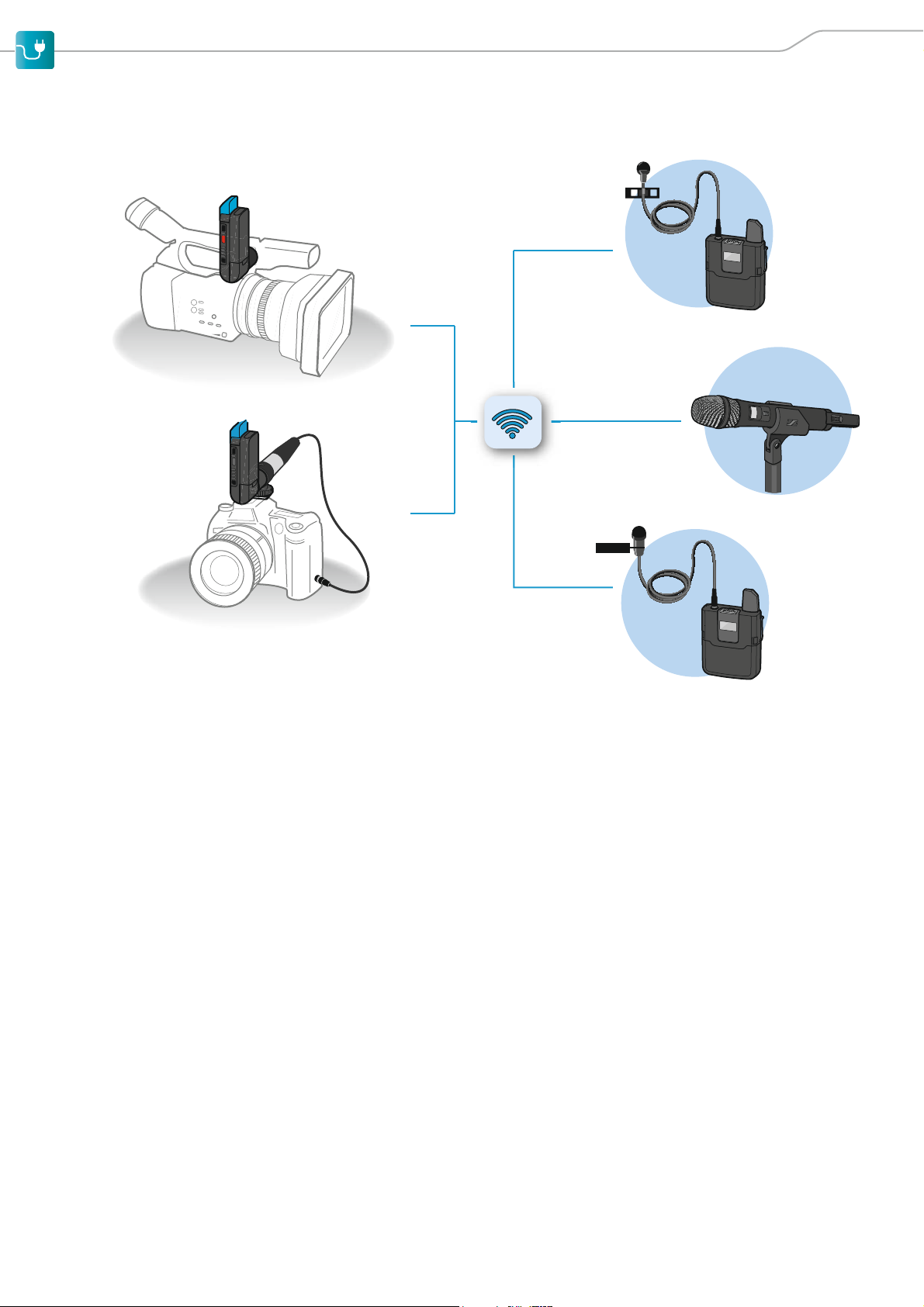
Putting the products into operation
Putting the products into operation
Avoiding sources of interference Featuring automatic interference management, the devices are capable of
avoiding interfering signals at any time by automatically moving together to
unused frequencies in the 1.9 GHz frequency band, without any audio interruption. However, the number of usable radio links is reduced if there are
active sources of interference in the vicinity of the devices.
왘 Maintain a distance to sources of interference in the 1.9 GHz frequency
band.
Possible sources of interference are e.g. base stations of DECT telephones.
WiFi, Bluetooth, Sennheiser ew D1, infrared remote controls and headphones
as well as UHF radio links such as Sennheiser evolution wireless G3 do not
represent sources of interference. You do not have to maintain a distance to
such equipment.
Direct line of sight Walls and other obstacles will reduce the range. Therefore, there should
always be a direct line of sight between the transmitting antenna and the
receiving antenna of a radio link.
AVX 13
Page 16
Putting the products into operation
max. 320°
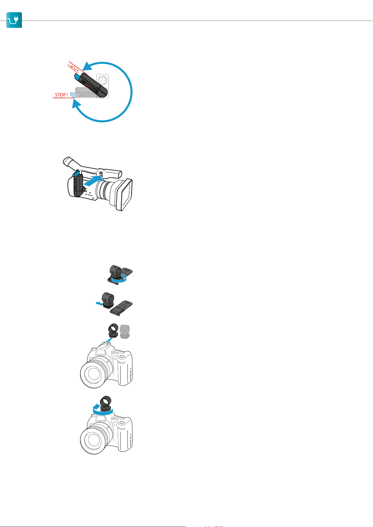
Putting the receiver into operation
The receiver can be rotated by a maximum angle of 320° around its XLR-3
connector.
Mounting the receiver to a video camera
To mount the receiver to a video camera, proceed as follows:
왘 Plug the receiver‘s rotatable XLR connector into the camera‘s XLR-3 audio
input.
If the video camera has an XLR-3 audio input with P48 phantom power, the
receiver is automatically switched on and off together with the video camera – provided that the phantom power is automatically switched on and
off together with the camera.
왘 Rotate the receiver into position, making sure that it does not disturb dur-
ing filming and that there is – preferably – a direct line of sight to the transmitter.
Mounting the receiver to a digital single-lens reflex camera
To mount the receiver to a DSLR camera, use the supplied EKP AVX adapter.
The adapter consists of a hot shoe adapter and a belt clip.
왘 Loosen the locking screw.
왘 Remove the hot shoe adapter from the belt clip.
왘 Slide the hot shoe adapter onto the hot shoe of the DSLR camera as shown
on the left.
왘 Fasten the hot shoe adapter using the locking screw .
14 AVX
Page 17
Putting the products into operation
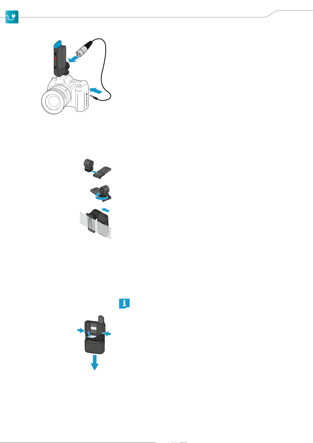
왘 Plug the receiver‘s rotatable XLR connector into the hot shoe adapter.
왘 Connect the XLR-3 socket of the supplied CI 400 adapter cable to the XLR-
3 connector of the receiver.
왘 Connect the 3.5 mm jack plug of the CI 400 adapter cable to the 3.5 mm
audio output of the DSLR camera.
Attaching the receiver using the belt clip
You can use the belt clip to attach the receiver to e.g. a belt or to the camera
bag.
Proceed as follows:
왘 Slide the hot shoe adapter onto the belt clip.
왘 Fasten the hot shoe adapter to the belt clip using the locking screw.
왘 Plug the receiver‘s rotatable XLR-3 connector into the hot shoe adapter as
shown on the left.
왘 Use the belt clip to attach the receiver to a camera bag or a belt.
Putting the bodypack transmitter into operation
Removing/inserting the accupack
You can power the bodypack transmitter with the supplied BA 30 accupack.
The accupack must be charged before first time use. The accupack can remain
in the bodypack transmitter for charging.
Before using the bodypack transmitter for the first time, remove the
protective foil from its accupack.
To remove the accupack from the bodypack transmitter:
왘 Simultaneously press the two catches and pull the accupack away from the
bodypack transmitter.
왘 Remove the protective foil.
AVX 15
Page 18
Putting the products into operation
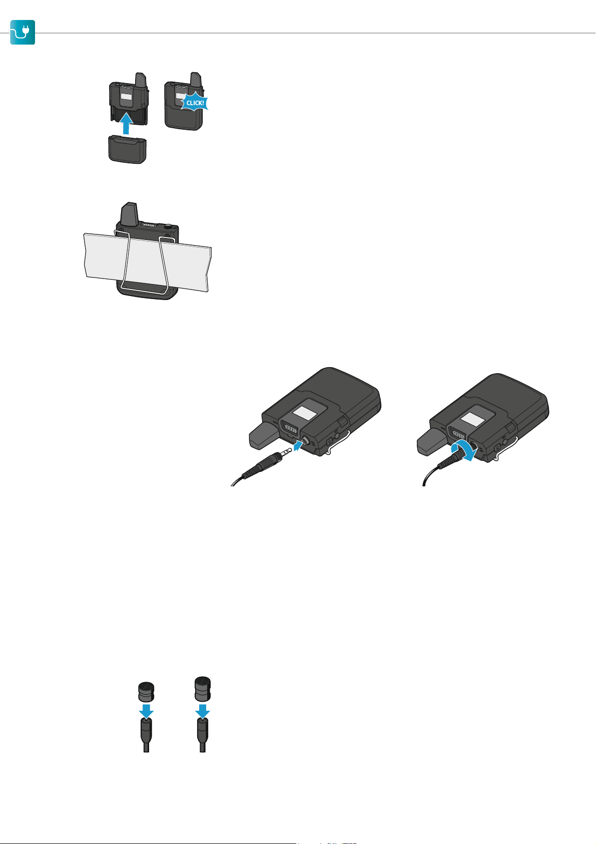
To insert the accupack into the bodypack transmitter:
왘 Slide the accupack onto the bodypack transmitter as shown.
The accupack locks into place with an audible click.
Attaching the bodypack transmitter to clothing
왘 Use the belt clip to attach the bodypack transmitter to clothing.
- The antenna of the bodypack transmitter should not be touched or covered during transmission as this would reduce the transmission range.
- There should be a free line of sight between the antenna of the bodypack
transmitter and the receiving antenna.
Connecting a clip-on microphone to the bodypack transmitter
Only connect one of the clip-on microphones recommended by Sennheiser.
These microphones are optimized for the bodypack transmitter.
왘 Connect the jack plug of the clip-on microphone to the 3.5 mm jack socket
(Mic/Line) of the bodypack transmitter.
왘 Lock the jack plug by screwing down the coupling ring.
Putting the clip-on microphones into operation
Putting the MKE 2 into operation
The MKE 2 clip-on microphone is supplied with the Lavalier Set Pro and meets
the highest demands on sound quality and ruggedness.
Using the frequency response caps You can use the supplied frequency response caps to boost the frequency
response of the MKE 2 (e.g. if the sound is too muffled) and to optimize your
recordings by improving the speech intelligibility.
왘 Slip the frequency response cap of your choice onto the microphone capsule
until it locks into place.
- The (small) MZC 2-1 frequency response cap slightly increases the treble
response of the microphone.
- The (large) MZC 2-2 frequency response cap allows you to increase the
treble frequencies to a greater extent.
16 AVX
Page 19
Putting the products into operation
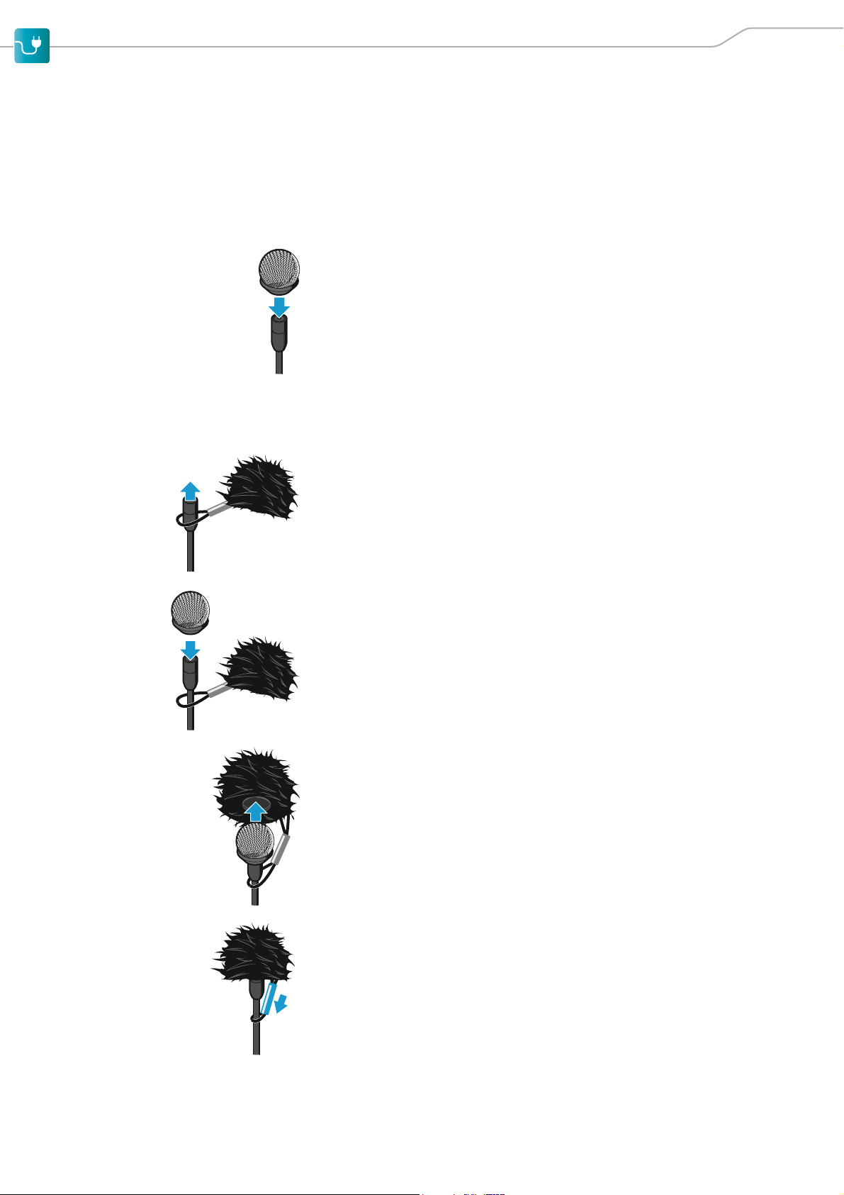
Using the windshield In order to avoid annoying wind noise during recording, we recommend using
a suitable windshield.
The MKE 2 is supplied with a metal windshield and a fur windshield. To begin
with, use the metal windshield which reduces wind noise by up to 20 dB. With
the additional fur windshield, you can reduce wind noise by a further 10 dB.
The fur windshield can only be used together with the metal windshield.
To use the metal windshield:
왘 Slip the metal windshield onto the microphone capsule of the MKE 2.
The microphone is ready for operation and can be attached to clothing by
means of the supplied microphone clip (see page 18).
To use the fur windshield:
왘 If you are already using the metal windshield or one of the frequency
response caps, remove them from the microphone capsule.
왘 Stretch open the retaining loop of the fur windshield by moving the sleeve
towards the fur.
Make sure you do not accidentally remove the sleeve from the retaining
loop.
왘 Pass the microphone through the retaining loop of the fur windshield.
The retaining loop now fits loosely around the connection cable of the
MKE 2.
왘 Slip the metal windshield onto the microphone capsule.
왘 Carefully stretch the opening of the fur windshield and slide it over the
metal windshield. Make sure that the fur windshield completely covers the
metal windshield.
왘 Use the sleeve to tighten the retaining loop around the connection cable.
The retaining loop ensures that the fur windshield is securely attached to
the clip-on microphones.
AVX 17
Page 20
Putting the products into operation
1
2
3
4
5
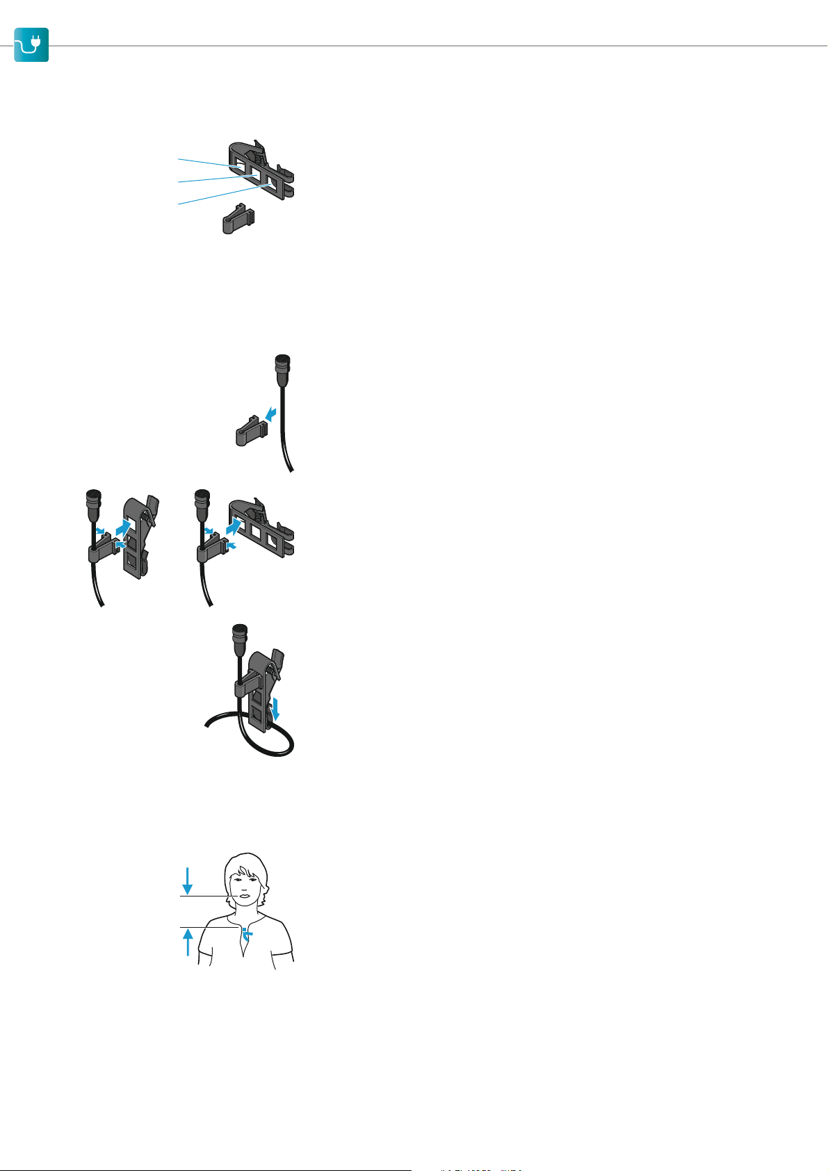
Attaching the clip-on microphone
to clothing
The MKE 2 is supplied with a microphone clip that consists of two parts:
• a microphone holder 4
• a clip 5 for attaching the microphone to clothing
The clip has three holes. Inserting the microphone holder into one of the holes
influences the clip‘s contact pressure and thus ensures secure attachment of
the clip to clothing made of different materials:
•Hole1: for attaching the microphone clip to clothing made of very heavy
and tightly-woven materials
•Hole2: for attaching the microphone clip to clothing made of medium-
heavy materials
•Hole3: for attaching the microphone clip to clothing made of very thin
materials
왘 Snap the connection cable of the MKE 2 into the microphone holder.
왘 Insert the microphone holder into the desired hole of the microphone clip.
To do so, press the two ends of the microphone holder together and hook it
into the hole.
The microphone clip can be attached to clothing either vertically or horizontally. Make sure to insert the microphone holder into the hole according to
the desired orientation of the microphone clip.
25 cm
(10")
To vertically attach the microphone clip to clothing:
왘 Guide the connection cable through the cable grip of the clip.
왘 Use the microphone clip to attach the clip-on microphone to clothing (e.g.
lapel, collar, tie).
왘 Conduct the connection cable so that noise due to friction is avoided and
that the connection cable and the antenna do not cross.
왘 Attach the microphone at a distance of approx. 25 cm to the mouth.
The MKE 2 clip-on microphone has an omni-directional pick-up pattern. It is
therefore not necessary to position it precisely.
18 AVX
Page 21
Putting the products into operation
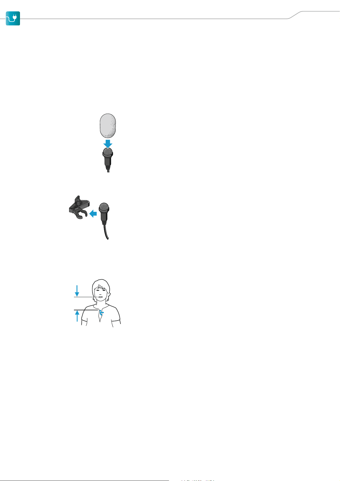
Using the windshield In order to avoid annoying wind noise during recording, we recommend using
Putting the ME 2 into operation
The ME 2 clip-on microphone is supplied with the Lavalier Set and provides
professional recordings with a high degree of speech intelligibility.
a suitable windshield.
The ME 2 is supplied with a foam windshield which reduces wind noise by up
to 10 dB.
To use the foam windshield:
왘 Slip the foam windshield onto the metal windshield of the ME 2.
Attaching the ME 2 to clothing The ME 2 clip-on microphone is supplied with a microphone clip.
왘 Snap the microphone into the holder of the microphone clip.
The microphone clip can be attached to clothing either vertically or horizontally. To do so, turn the holder so that the microphone is correctly positioned.
왘 Use the microphone clip to attach the clip-on microphone to clothing (e.g.
lapel, collar, tie).
왘 Conduct the connection cable so that noise due to friction is avoided and
that the connection cable and the antenna do not cross.
왘 Attach the microphone at a distance of approx. 25 cm to the mouth.
The ME 2 clip-on microphone has an omni-directional pick-up pattern. It is
25 cm
(10")
therefore not necessary to position it precisely.
AVX 19
Page 22
Putting the products into operation
5-10 cm
Putting the handheld transmitter into operation
The handheld transmitter is available both with and without Mute switch and
comes with different microphone heads.
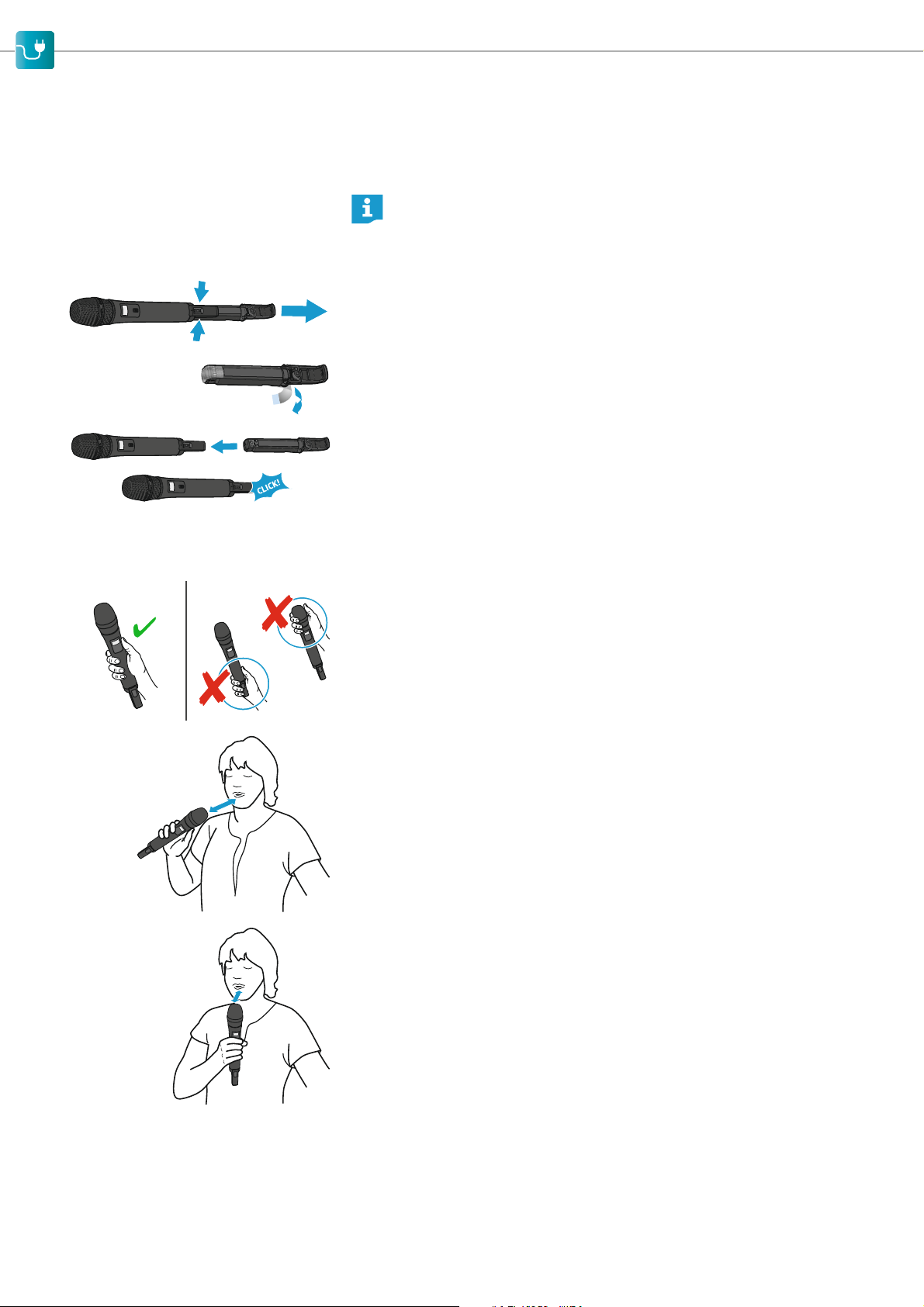
Before using the handheld transmitter for the first time, remove the
protective foil from its accupack.
Removing/inserting the accupack
To remove the accupack:
왘 Simultaneously press the two catches and pull the accupack away from the
handheld transmitter.
왘 Remove the protective foil.
To insert the accupack:
왘 Slide the accupack onto the handheld transmitter as shown.
The accupack locks into place with an audible click.
5-10 cm
Holding the handheld transmitter
If you cover the antenna of the handheld transmitter during transmission, the
transmission range will be considerably reduced. If you cover the microphone
head during transmission, this will change the pick-up pattern of the microphone and consequently the sound.
왘 Only hold the handheld transmitter by its body.
왘 Hold the handheld transmitter approx. 5 to 10 cm in front of your mouth.
The MMD 835-1 microphone head has a cardioid pick-up pattern:
왘 You can speak into the sound inlet basket from directly above or from
slightly off-axis.
The MMD 42-1 microphone head has an omni-directional pick-up pattern:
왘 It is not necessary to orient the microphone directly towards the mouth.
The microphone can also be used by several people simultaneously.
20 AVX
Page 23
Putting the products into operation
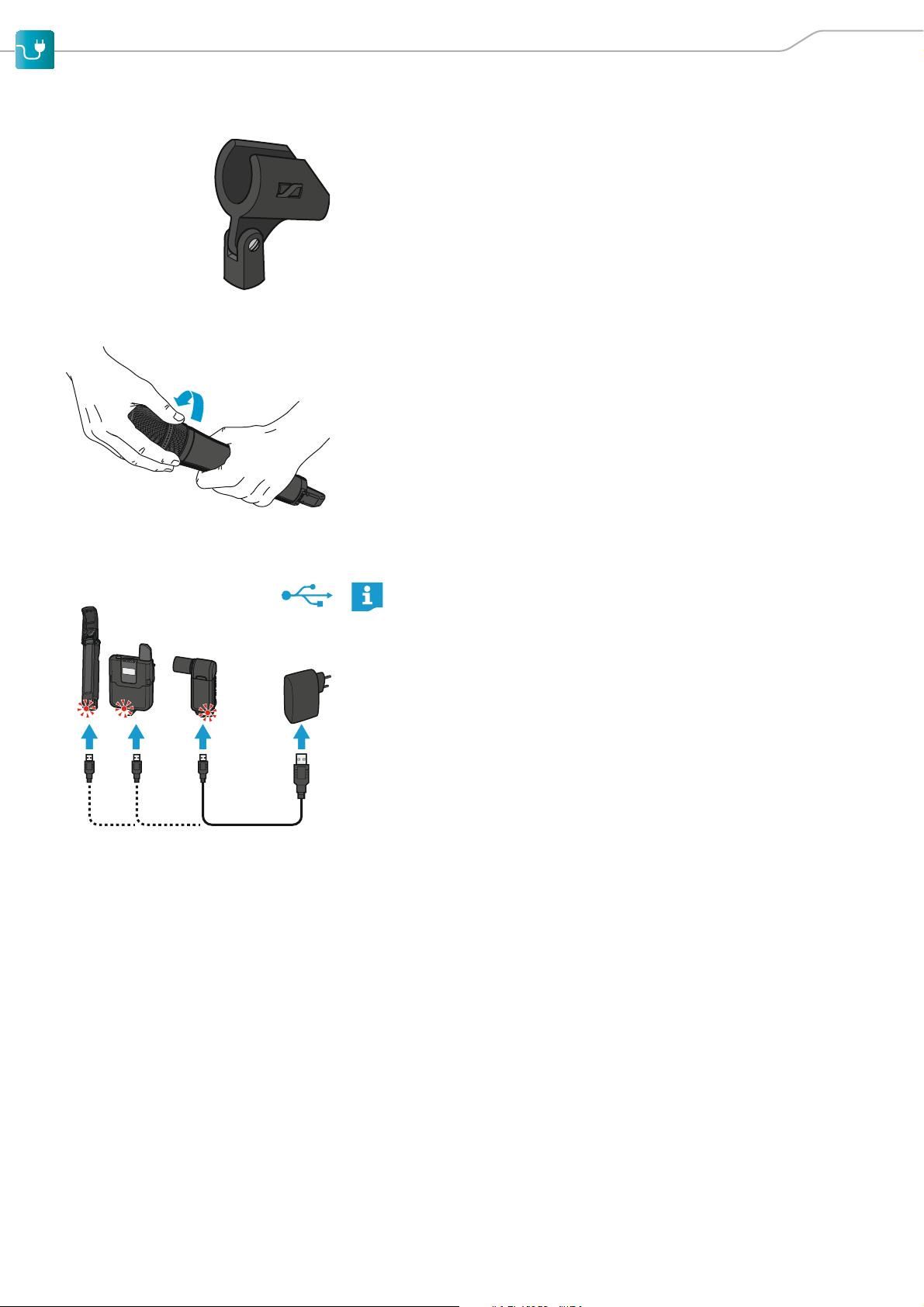
Attaching the handheld transmitter to the microphone stand clamp
왘 Screw the thread to the stand and tighten the screw.
왘 Place the handheld transmitter into the microphone clamp.
왘 Tilt the handheld transmitter so that it is oriented towards the mouth.
Changing the microphone head
The handheld transmitter comes in different sets, including either the
MMD 835-1 or the MMD 42-1 microphone head. You can unscrew the microphone head and replace it by another one, e.g. one with a different pick-up
pattern.
BA 10/BA 30 BA 20
Recharging the accupack
You can recharge the supplied BA 10, BA 20 and BA 30 accupacks as
follows:
• using the Sennheiser NT 5-10U USB power supply/charger
• using a standard USB power supply/charger
• via the USB port of a computer
• via a USB hub with its own power supply
• via a mobile USB power supply (power bank)
Charging the accupacks using the NT 5-10U power supply/charger
The BA 20 accupack of the receiver and the BA 30 accupack of the bodypack
transmitter can remain in their respective devices for charging. To charge the
BA 10 accupack of the handheld transmitter:
왘 Remove the accupack from the handheld transmitter (see page 15).
왘 If the accupack‘s micro USB socket has a cover flap:
Open the cover flap of the micro USB socket of the accupack and connect
the micro USB connector of the USB cable to the micro USB socket of the
accupack.
To charge the accupack via the USB port of a computer or a mobile USB power
supply (power bank):
왘 Connect the USB connector of the USB cable to a USB socket of the com-
puter or the mobile USB power supply.
왘 Switch the computer or the mobile USB power supply on.
AVX 21
Page 24

Putting the products into operation
To charge the accupack using any USB power supply/charger or a USB hub
with external power supply:
왘 Connect the USB connector of the USB cable to the USB socket of the USB
power supply/charger or to the USB hub.
왘 Plug the USB power supply/charger or the power supply unit of the USB hub
into the wall socket.
The charge status LED of the accupack lights up red when the accupack is
being charged. The charge status LED of the accupack lights up green when
the accupack is fully charged.
Accupack
BA 10
(handheld transmitter)
BA 20
(receiver)
BA 30
(bodypack transmitter)
Charging time required for a capacity of ...
… 30 % … 60 % … 75 % … 100 %
1:00 h 2:00 h 3:00 h 4:30 h
0:15 h 0:30 h 0:40 h 1:15 h
1:00 h 2:00 h 3:00 h 4:30 h
22 AVX
Page 25
Using the products
SHORT = ON
LONG = OFF
Using the products
AVX offers true ease of use:
• The devices of a set are factory pre-paired and ready for immediate use.
• The system features automatic frequency management and automatically
searches for free transmission frequencies.
• AVX also features automatic interference management and inaudibly shifts
to a new frequency if interference occurs.
• The system also sets the correct microphone sensitivity automatically.
• Sound that is too loud or, even worse, too quiet is now a thing of the past.
Switching the devices on or off
After switch-on, the receiver and the transmitter will take approx.
10 seconds to establish the radio link. The more sources of interference
there are and the more AVX devices you switch on, the longer it takes
to establish the radio links.
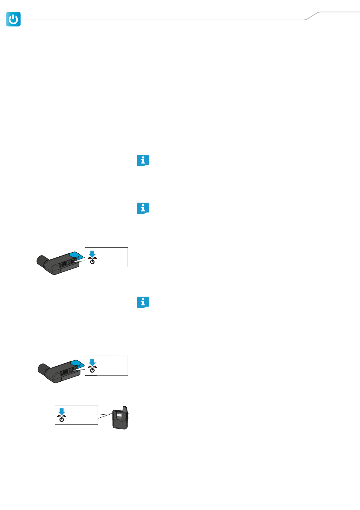
Switching the receiver on
If the receiver is connected to an XLR-3 audio input with P48 phantom
power, the receiver is automatically switched on together with the
video camera – provided that the phantom power is automatically
switched on together with the camera.
To manually switch the receiver on:
왘 Short-press the On/Off/Check button.
The status LED indicates the current status of the receiver (see page 7). The
radio link to the last paired transmitter is established automatically as soon
as the paired transmitter is switched on.
Switching the receiver off
If the receiver is connected to an XLR-3 audio input with P48 phantom
power, the receiver is automatically switched off together with the
video camera – provided that the phantom power is automatically
switched off together with the camera. If, after switch-off of the video
camera, the phantom power drops only slowly, the receiver can take up
to one minute to switch off.
To manually switch the receiver off:
왘 Long-press the On/Off/Check button.
The status LED goes off.
Switching the bodypack transmitter on
왘 Short-press the On/Off button.
SHORT = ON
AVX 23
The display panel and the status LED indicate the current status of the
bodypack transmitter (see page 10 and page 11). The radio link to the last
paired receiver is automatically established as soon as the paired receiver
is switched on.
Page 26
Using the products
LONG = OFF
SHORT
> 3 h
> 2 h
> 1 h
> 15 min
< 15 min
!
Check
Check
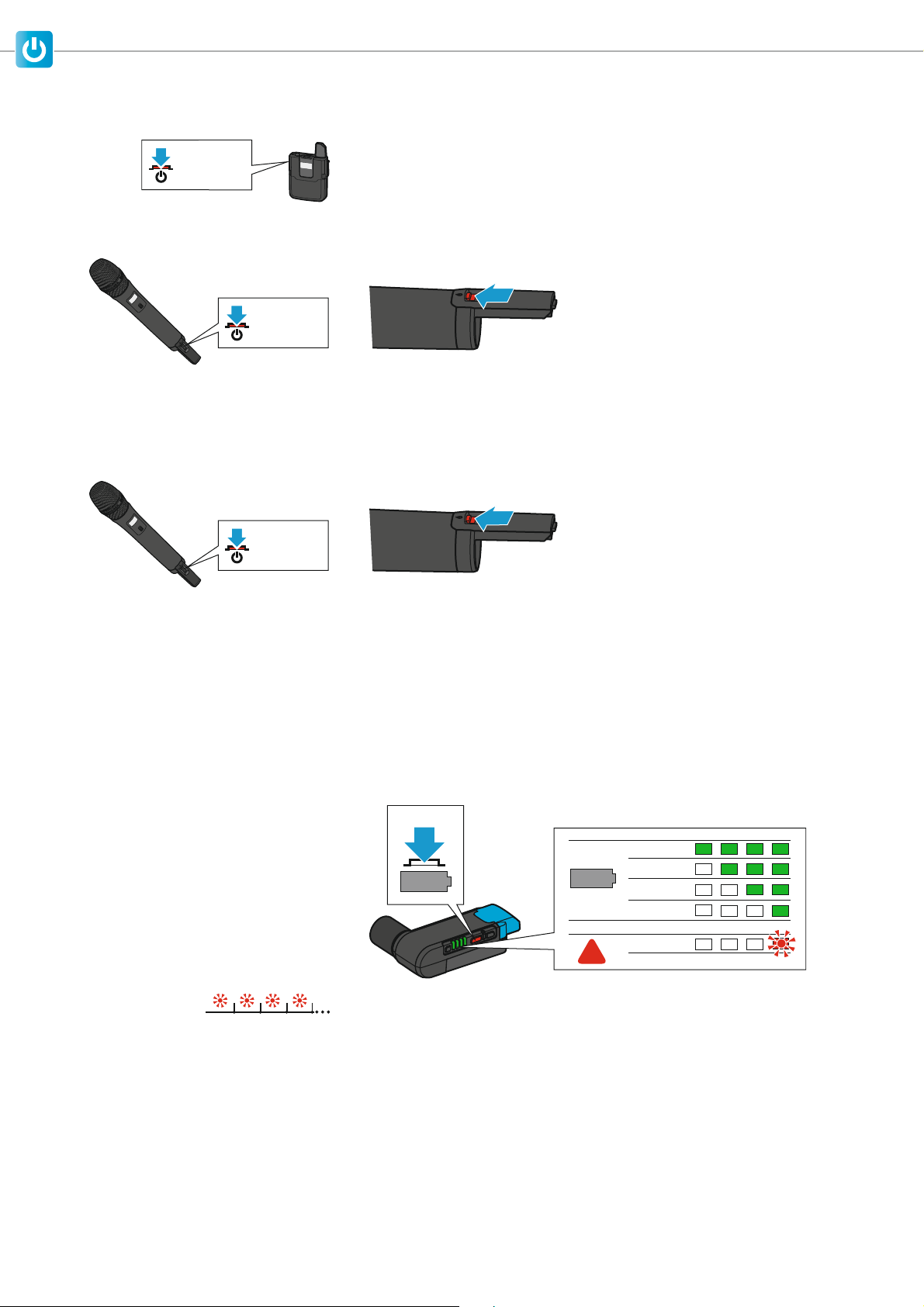
Switching the bodypack transmitter off
왘 Long-press the On/Off button.
The display panel and the status LED go off.
Switching the handheld transmitter on
왘 Briefly slide the On/Off button in the direction of the transmitter body.
SHORT = ON
The display panel and the status LED indicate the current status of the
handheld transmitter (see page 9 and page 11). The radio link to the last
paired receiver is automatically established as soon as the paired receiver
is switched on.
Switching the handheld transmitter off
왘 Slide and hold the On/Off button in the direction of the transmitter body.
LONG = OFF
The display panel and the status LED go off.
Checking the charge status of the accupacks
Checking the charge status of the BA 20 accupack in the receiver
To display the expected remaining battery life of the BA 20 accupack in the
receiver:
왘 Short-press the On/Off/Check button.
The 4-step LED display lights up green to indicate the expected remaining
battery life.
When the right LED of the 4-step LED display flashes red – regardless of
whether the On/Off/Check button has been pressed –, the capacity of the
BA 20 accupack is only sufficient for less than 15 minutes of operation.
24 AVX
Page 27
Using the products
AVX 1080
10 h
AVX 1080
Mic
Mute
Checking the charge status of the BA 10 accupack in the handheld transmitter or of the BA 30 accupack in the bodypack transmitter
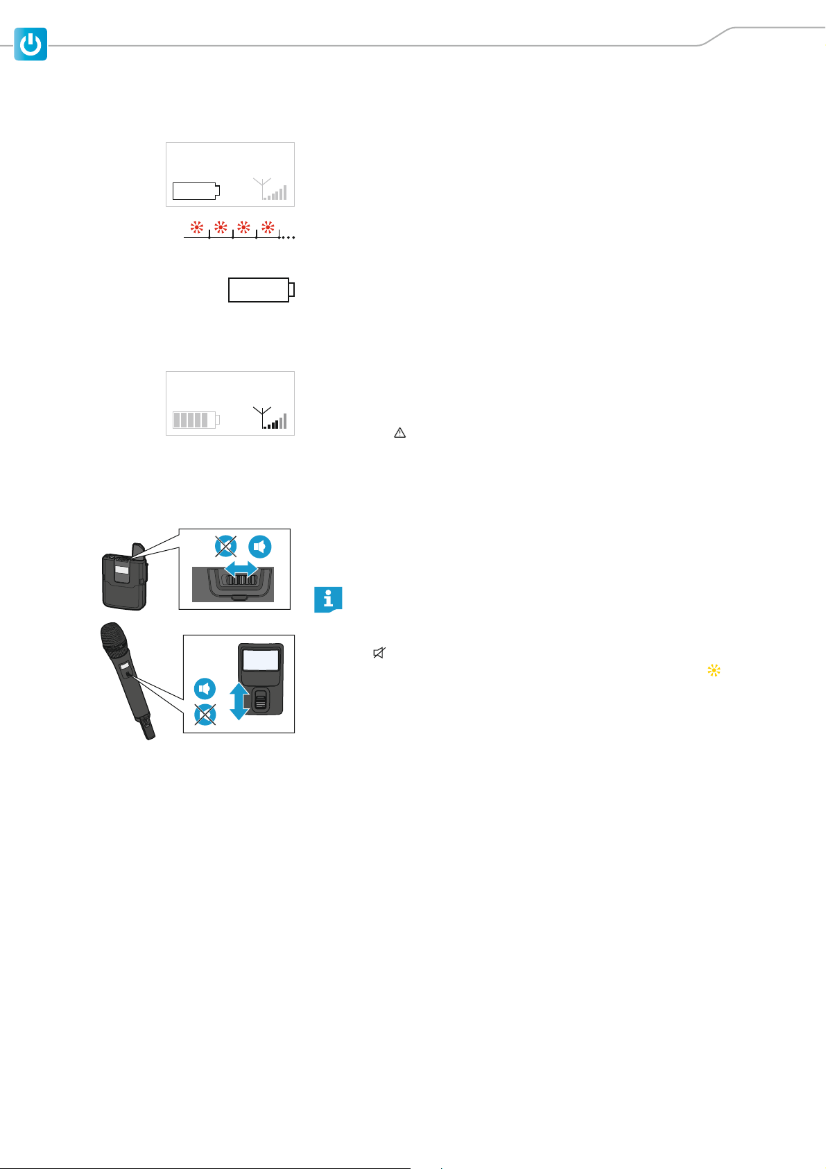
The expected remaining battery life of the accupack is indicated by a battery
icon on the transmitter display panel.
When the capacity of the accupack is so low that the remaining battery life is
less than 30 minutes, the status LED on both the transmitter and the receiver
flashes red.
In addition, the empty battery icon flashes on the display panel of the transmitter.
Checking the RF signal level
The quality of the RF signal is shown on the display panel of the transmitter
If no RF signal is being transmitted, e.g. because the receiver is switched off or
out of range, all segments of the RF signal level display are grayed out. In addition, No Link is displayed on the display panel.
Mute
Muting the bodypack transmitter or the SKM AVX-S handheld transmitter
Both the bodypack transmitter and the SKM AVX-S handheld transmitter have
a Mute switch that mutes the audio signal without switching the transmitter
off.
The SKM AVX handheld transmitter has no Mute switch and can therefore not be muted.
왘 Slide the Mute switch to the position Mute.
Muted appears on the display panel of the transmitter. The status LED
on both the transmitter and the paired receiver lights up yellow .
왘 Slide the Mute switch to the position Mic to unmute the audio signal.
AVX 25
Page 28
Using the products
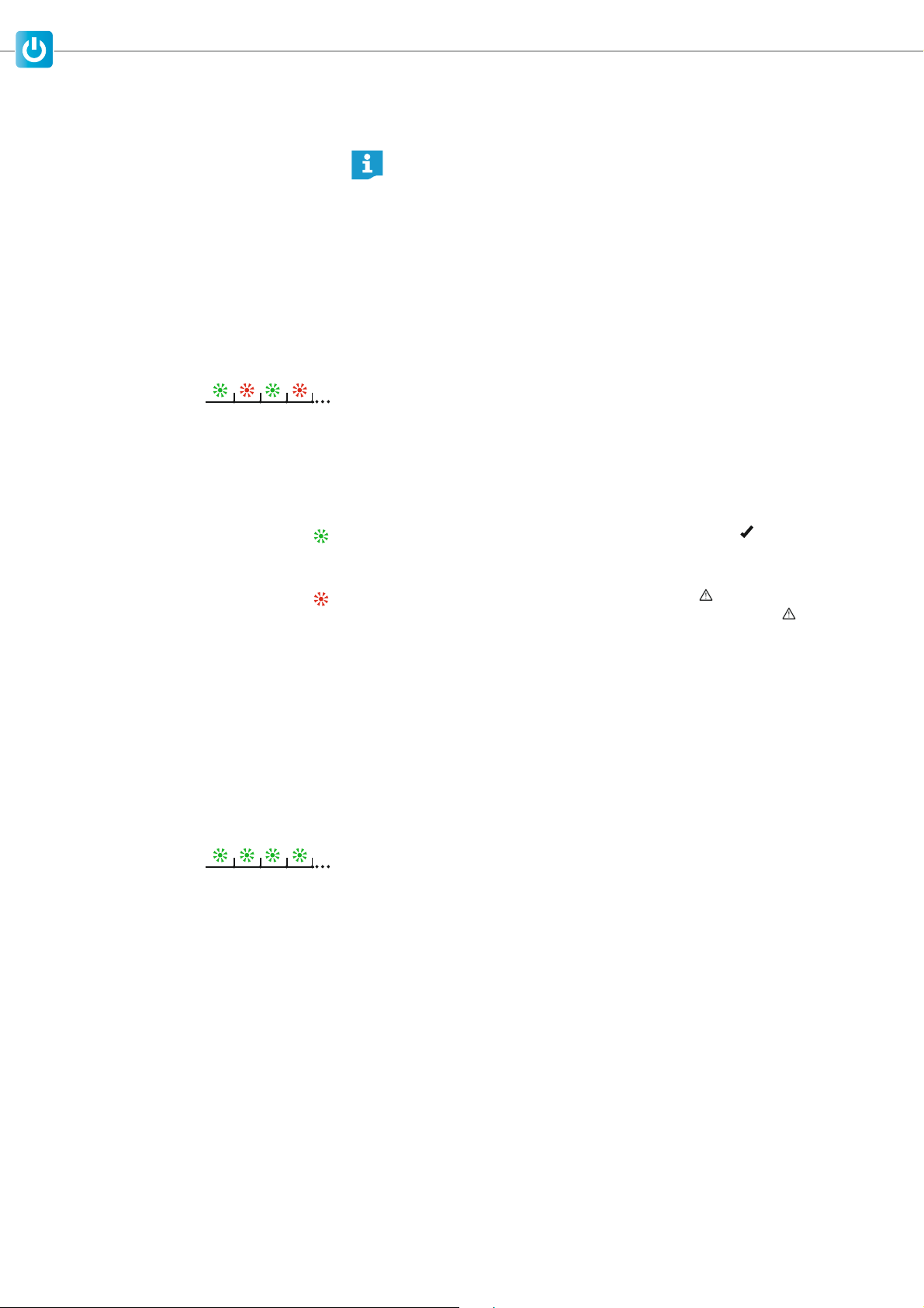
Pairing a receiver with a transmitter
The receiver and the transmitter of a set are factory pre-paired and
therefore ready for immediate use. The radio link is automatically
established as soon as both devices are switched on. You can disconnect the existing radio link and establish new radio links to two other
devices.
To establish a new radio link between a receiver and a transmitter, proceed as
follows:
왘 Switch on the receiver and the transmitter that you want to pair (see
page 23).
The status LED on both the receiver and the transmitter indicates the current device status (see page 9).
왘 Long-press, one after the other, the Pair buttons of the receiver and the
transmitter to be paired until their status LEDs flash alternately green and
red. You have 120 seconds between pressing the first button and the second button.
Press pair on receiver appears on the transmitter display panel.
Existing radio links to other devices are now disconnected.
왘 Wait for approx. 10 seconds until the radio link is established.
- Once the radio link is successfully established, Paired appears on the
transmitter display panel and the status LED on both the transmitter and
the receiver lights up green.
- If no radio link can be established, Pairing failed briefly appears on the
transmitter display panel, followed by the message No Link . The status LED of the transmitter and/or the receiver lights up red.
For more information on potential problems when establishing a radio link,
refer to page 29.
Identifying paired devices
You can perform a pairing identification to see which transmitter is paired
with which receiver.
왘 Switch on all devices whose pairing you want to identify (see page 23).
왘 Short-press the Pair button of the receiver or of the transmitter.
The transmitter display panel displays the message This is AVX and the last
four digits of the serial number of the paired receiver. The status LEDs of
the paired devices flash green for 10 seconds.
If the receiver or the transmitter is not paired or if the paired device is not
switched on or out of range, the status LED does not flash green.
26 AVX
Page 29
Using the products
AF Out
–30 dBu
–20 dBu
–10 dBu
0 dBu
INPUT LEVEL
Auto
Manual
Displaying or adjusting the receiver‘s audio output level
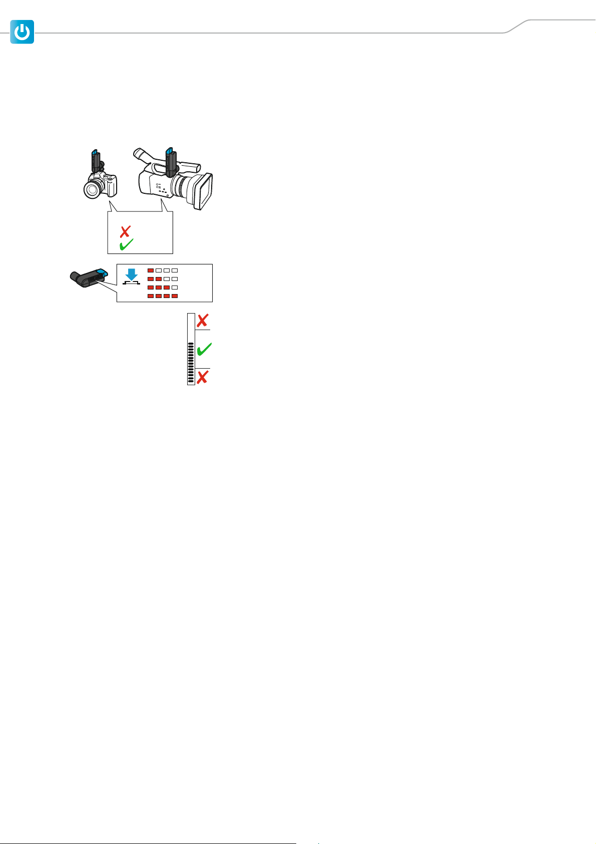
To display and correctly adjust the receiver‘s output level:
왘 Make sure that the radio link is established.
왘 If your video or DSLR camera has an automatic level control, the automatic
level control must be deactivated.
The receiver also has an automatic level control which cannot be deactivated. If both the automatic level control of the video camera and the automatic level control of the receiver are active, they will interfere with one
another.
왘 Short-press the AF Out button on the receiver.
The 4-step LED display indicates the current output level. This display automatically goes off after a while.
AUDIO
LEVEL
왘 Check the output level display on the video or DSLR camera while using the
microphone as usual.
The output level is adjusted correctly when the output level display shows
full deflection only during the loudest passages. If your video or DSLR camera has a clipping display, this must never light up.
If the output level is adjusted to low or too high:
왘 Short-press the AF Out button on the receiver while the 4-step LED display
is active.
The audio output level is reduced by one step each time the AF Out button
is pressed. When the lowest output level has been reached, you can press
the AF Out button again to reset the receiver to the highest output level.
왘 Alternatively, you can also adjust the input sensitivity of the video camera.
AVX 27
Page 30
Cleaning and maintaining the products
Cleaning and maintaining the products
Important safety information
ATTENTION
Liquids can damage the electronics of the devices
Liquids entering the housing of the devices can cause a short-circuit and damage the electronics.
왘 Only clean the devices with a soft, dry cloth.
ATTENTION
Damage to the surfaces of the devices
Solvents or cleansing agents can damage the surfaces of the devices.
왘 Do not use any solvents or cleansing agents.
왘 Use devices that are frequently worn on the body so that direct skin contact
and contact with sweat is avoided.
왘 Use a dry cloth to clean all devices that are frequently worn on the body
from time to time.
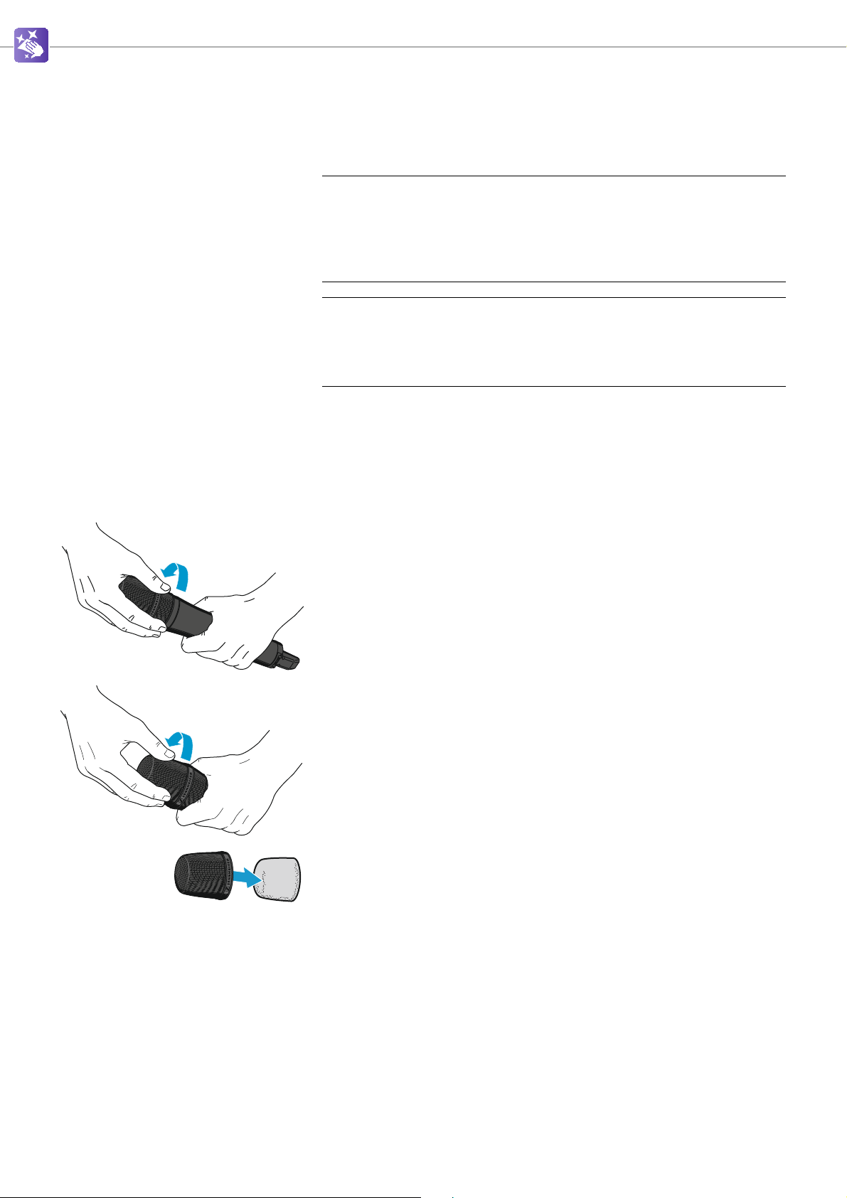
Cleaning the sound inlet basket of the handheld transmitter
왘 Unscrew the sound inlet basket from the handheld transmitter.
왘 Unscrew the upper part of the sound inlet basket from the lower part.
왘 Remove the foam insert from the upper part of the sound inlet basket.
왘 Use a dry cloth to clean the upper part of the sound inlet basket from the
inside and outside.
왘 Reinsert the foam insert into the upper part of the sound inlet basket.
왘 Screw the upper part of the sound inlet basket back to the lower part.
왘 Replace the sound inlet basket on the handheld transmitter and screw it
tight.
28 AVX
Page 31

If a problem occurs ...
If a problem occurs ...
Problem Possible cause Possible solution Page
No sound The receiver is not connected properly. • Connect the receiver properly. 14
The bodypack transmitter or the SKM AVX-S
handheld transmitter is muted. Muted
appears on the transmitter display panel and
the status LED on both the receiver and the
transmitter lights up yellow.
The transmitter and the receiver are not paired,
the status LED lights up red.
Sound distorted The automatic level control of the video camera
or the DSLR camera is active.
Sound too low The output level of the receiver and/or the input
sensitivity of the video camera is adjusted too
low.
Bad reception The distance between the transmitter and the
receiver is too high.
Devices take a very
long time to establish a radio link
The devices need more time to establish the
radio links because the distance between the
transmitter and the receiver is too large or
because there are many active interfering
sources in the vicinity of the devices.
• Set the Mute switch of the bodypack
transmitter or the SKM AVX-S handheld transmitter to the position Mic.
• Pair the devices properly. 26
Deactivate the automatic level control of
the video camera or the DSLR camera.
• Either increase the receiver‘s output
level
• or increase the video camera‘s input
sensitivity.
• Reduce the distance between the
transmitter and the receiver.
• Make sure that there is a direct line of
sight between the transmitter and the
receiver.
• Check the RF signal quality on the
transmitter.
• Move the paired transmitter closer to
the receiver.
25
27
13
13
–
Devices cannot be
paired
For more tips and answers to your questions, visit www.sennheiser.com/AVX-support
If a problem occurs that is not listed in the above table or if the problem cannot be solved with the proposed solutions,
please contact your local Sennheiser partner for assistance. To find a Sennheiser partner in your country, search at
www.sennheiser.com
No radio link • Reduce the distance between the
transmitter and the receiver.
• Make sure that there is a direct line of
sight between the transmitter and the
receiver.
Different country variants Transmitters and receivers of different
country variants cannot be paired with
each other.
under “Service & Support”.
13
AVX 29
Page 32
Specifications
AVX
Line +
Specifications
System
AF frequency response 20 to 20,000 Hz
Dynamic range > 120 dB (A)
THD (1 kHz) typ. 0,1 %
Audio sampling 24 bit/48 kHz
Signal-to-noise ratio > 90 dB (A)
RF frequency ranges 1,880 to 1,930 MHz (country-specific)
Modulation GFSK with back channel
Transmission method
Latency 19 ms
Relative air humidity max. 95 %
Temperature range
Operation:
Storage:
TDMA
fast switching antenna diversity
–10 °C to +55 °C
-20 °C to +70 °C
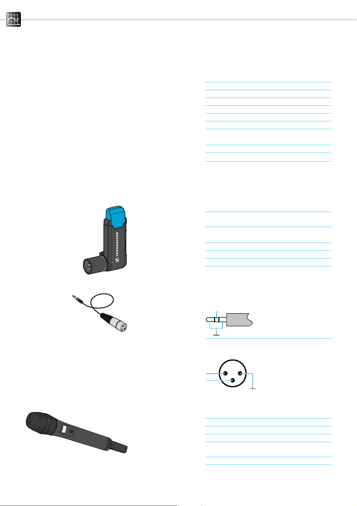
CI 400
EKP AVX
RF sensitivity < –90 dBm
RF output power of
back channel
Audio output
XLR, balanced
typ. 15 dBm e.i.r.p.
adjustable
–30 dBu to 0 dBu in 4 steps
Power supply BA 20 accupack (Li-Ion, 3.7 V DC)
Operating time > 4 h
AF connection socket XLR, male
Weight (incl. accupack) approx. 87 g
AF connector 3.5 mm jack plug, unbalanced
Connector assignment:
AF connection socket XLR, female
Pin assignment:
2
+
-
1
3
SKM AVX
RF output power adaptive, up to 250 mW (country-specific)
AF frequency response 50 to 20,000 Hz
Input sensitivity automatic sensitivity adjustment
Power supply BA 10 accupack (Li-Ion, 3.6 V DC)
Operating time
with accupack
typ. 15 h
Display LCD
Weight (without accupack)approx. 282 g incl. microphone head
30 AVX
Page 33
Specifications
Line +
Mic +
SK AVX
RF output power adaptive, up to 250 mW (country-specific)
AF frequency response
Mic:
Line:
Max. input level
Mic:
Line:
Line input impedance 1 MΩ
Input sensitivity automatic sensitivity adjustment
Power supply BA 30 accupack (Li-Ion, 3.7 V DC)
Operating time
with accupack
AF connection socket 3 5 mm jack socket, lockable
50 to 20,000 Hz
20 to 20,000 Hz
2.2 V RMS
3.3 V RMS
typ. 15 h
Connector assignment:
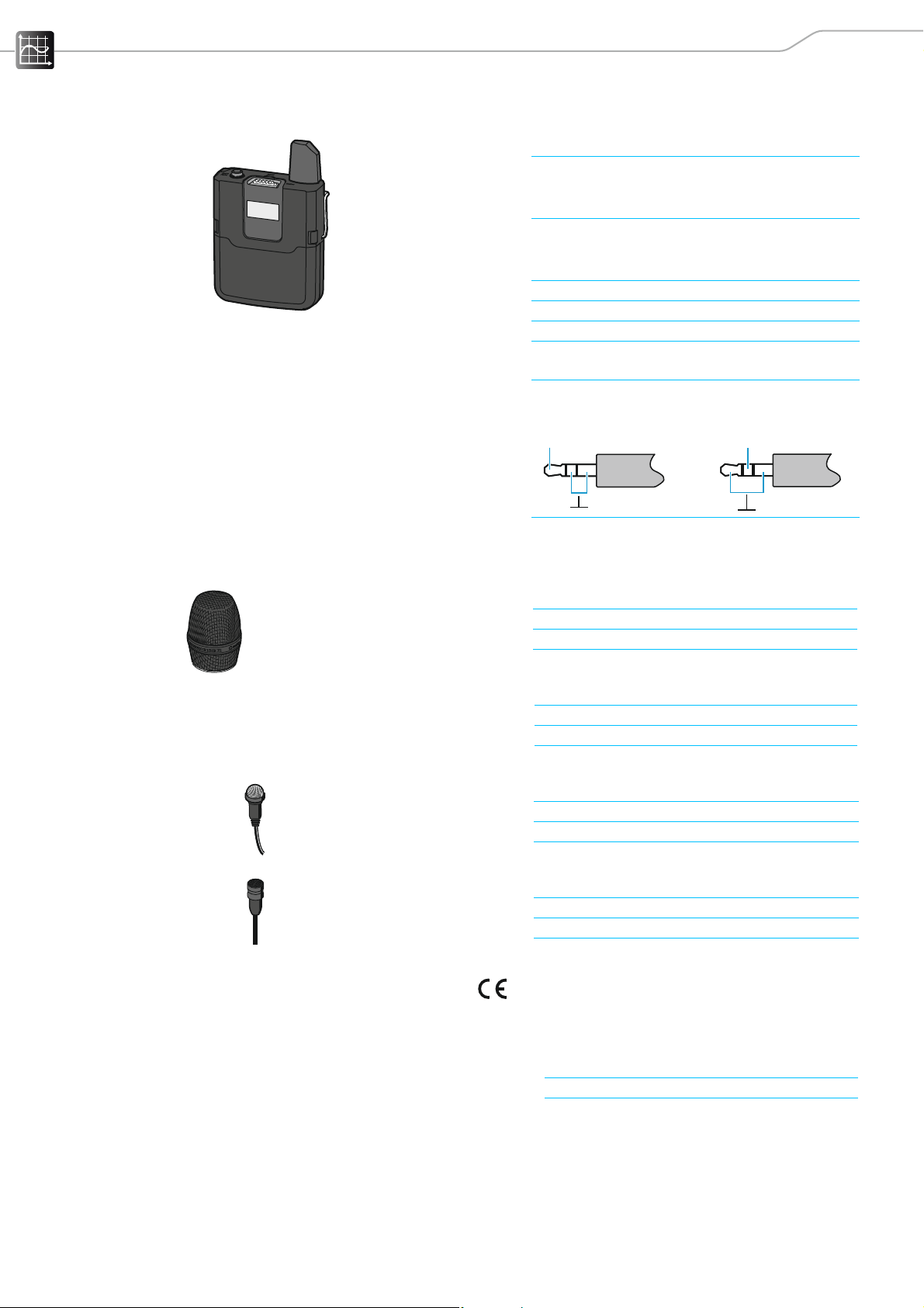
MMD 835-1
MMD 42-1
ME 2
MKE 2
Weight (without accupack)approx. 87 g
Microphones
Microphone type dynamic
Sensitivity 2.1 mV/Pa
Pick-up pattern cardioid
Max. SPL 154 dB SPL
Microphone type dynamic
Sensitivity 1.8 mV/Pa
Pick-up pattern omni-directional
Max. SPL 154 dB SPL
Microphone type pre-polarized condenser microphone
Sensitivity 20 mV/Pa
Pick-up pattern omni-directional
Max. SPL 130 dB SPL
Microphone type pre-polarized condenser microphone
Sensitivity 5 mV/Pa
Pick-up pattern omni-directional
Max. SPL 142 dB SPL
In compliance with:
AVX 31
Europe Radio
EMC
Safety
RoHS
USA FCC 47 CFR 15
Canada Industry Canada RSS 210
CAN ICES-3(B)/NMB-3(B)
EN 301406
EN 301489-1/-6
EN 60950-1,
EN 62311 (SAR)
EN 50581
Page 34
Specifications
C
US
Approved by:
NT 5-10U
USA
SKM
SK
EKP
FCC ID: DMOSKM1G49WE
FCC ID: DMOSK1G9WE
FCC ID: DMOEKP1G9WE
Canada
SKM
SK
EKP
IC: 2099A-SKM1G9WE
IC: 2099A-SK1G9WE
IC: 2099A-EKP1G9WE
Australia/New Zealand
R 202-SMC049
SKM
R 202-SMC050
Japan
SK
R 202-SMC051
EKP
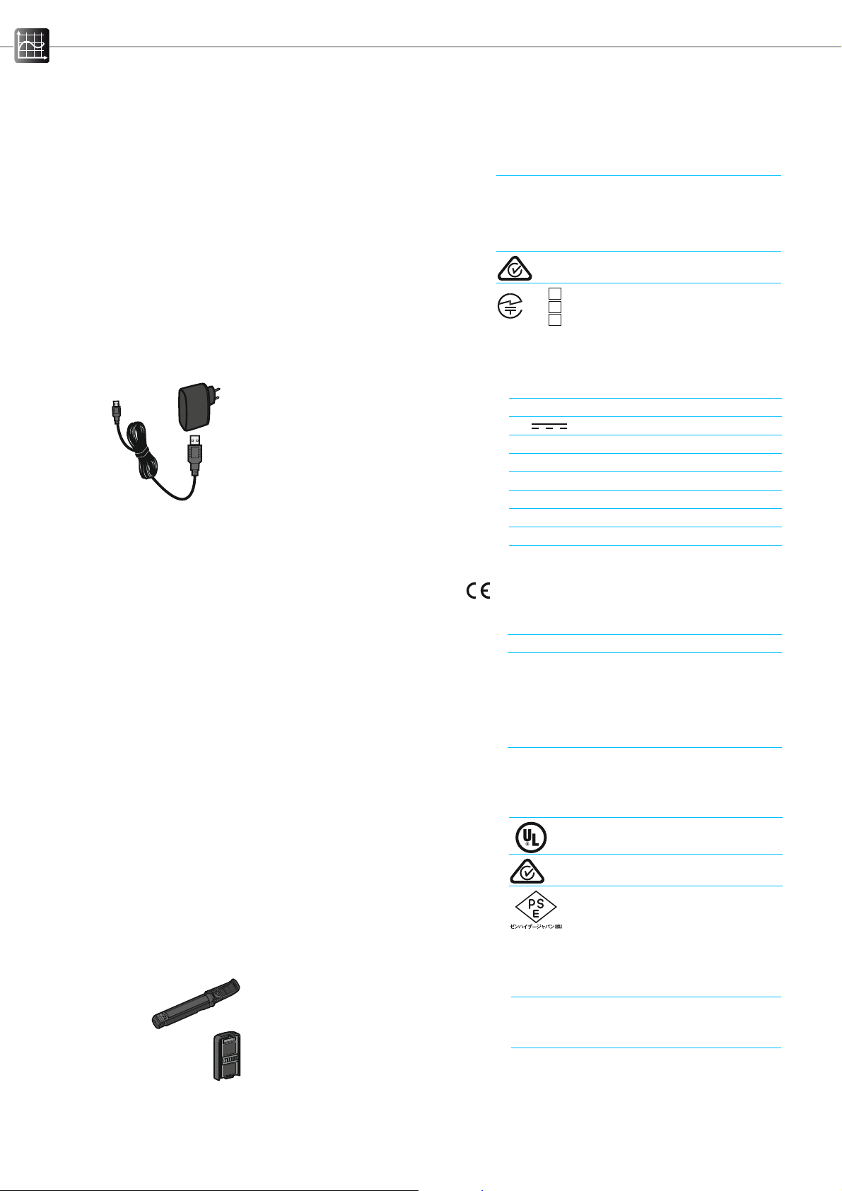
USB power supply/charger
Nominal input voltage 100 to 240 V~
Power frequency 50 or 60 Hz
Nominal output voltage 5 V
Output current 1 A
Standby power consumption ≤ 0.1 W
Energy efficiency level V
Operating temperature 0 °C to +40 °C
Storage temperature –20 °C to +70 °C
Relative air humidity max. 90 %
Weight approx. 55 g
In compliance with:
Certified by:
BA 10
Europe EMC
Safety
RoHs
Commission Regulation (EC) No. 1275/2008
USA/Canada EMC
Safety
Australia EMC
Safety
Europe ENEC 22 SIQ
USA/Canada
Australia/New Zealand
Japan
Accupacks
Charging capacity 2,200 mAh
Output voltage 3.6 V
EN 55022, EN 55024, EN 60950-1
EN 50581
FCC 47 CFR 15 B
ICES 003
CAN ICES-3(B)/NMB-3(B)
UL 60950-1
CAN/CSA-C22.2 No. 60950-1
AS/NZ CISPR 22
AS/NZL 60950.1
BA 20
Charging capacity 430 mAh
Output voltage 3.7 V
32 AVX
Page 35
Specifications
51 mm
81 mm
21 mm
ca. 275 mm
40 mm
100 mm
65 mm
24 mm
BA 30
In compliance with:
Certified by:
Charging capacity 2,030 mAh
Output voltage 3.7 V
Europe EMC
Safety
USA/Canada Rechargeable
battery cells
Accupack
EN 301489-1/-6/-17
IEC/EN 62133
UL 1642
UL 2054
Japan DENAN Ordinance Article 1;
Appendix 9 Lithium Ion
Korea
Safety K 62133
UN transportation test according to UN Manual of Tests and Criteria,
Part III, section 38.3 Lithium-Ion batteries
USA/Canada
Japan
Korea
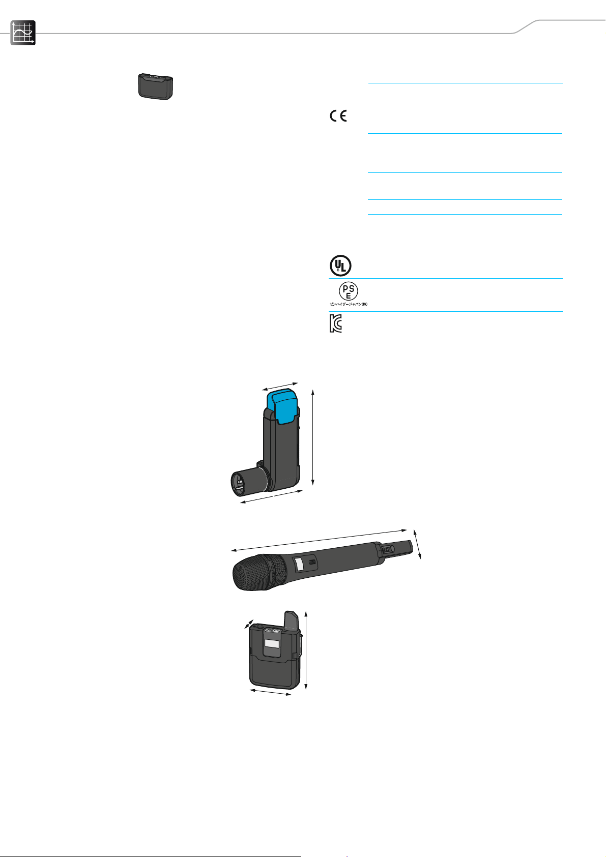
Dimensions
Receiver
Handheld transmitter
Bodypack transmitter
AVX 33
Page 36

Specifications
Licenses
CELT Codec
Copyright (c) 2014 IETF Trust and the persons identified as authors of the
code. All rights reserved.
Redistribution and use in source and binary forms, with or without modification, are permitted provided that the following conditions are met:
• Redistributions of source code must retain the above copyright notice, this
list of conditions and the following disclaimer.
• Redistributions in binary form must reproduce the above copyright notice,
this list of conditions and the following disclaimer in the documentation
and/or other materials provided with the distribution.
• Neither the name of Internet Society, IETF or IETF Trust, nor the names of
specific contributors, may be used to endorse or promote products derived
from this software without specific prior written permission.
THIS SOFTWARE IS PROVIDED BY THE COPYRIGHT HOLDERS AND CONTRIBUTORS “AS IS” AND ANY EXPRESS OR IMPLIED WARRANTIES, INCLUDING, BUT
NOT LIMITED TO, THE IMPLIED WARRANTIES OF MERCHANTABILITY AND FITNESS FOR A PARTICULAR PURPOSE ARE DISCLAIMED. IN NO EVENT SHALL THE
COPYRIGHT HOLDER OR CONTRIBUTORS BE LIABLE FOR ANY DIRECT, INDIRECT,
INCIDENTAL, SPECIAL, EXEMPLARY, OR CONSEQUENTIAL DAMAGES (INCLUDING,
BUT NOT LIMITED TO, PROCUREMENT OF SUBSTITUTE GOODS OR SERVICES; LOSS
OF USE, DATA, OR PROFITS; OR BUSINESS INTERRUPTION) HOWEVER CAUSED
AND ON ANY THEORY OF LIABILITY, WHETHER IN CONTRACT, STRICT LIABILITY,
OR TORT (INCLUDING NEGLIGENCE OR OTHERWISE) ARISING IN ANY WAY OUT
OF THE USE OF THIS SOFTWARE, EVEN IF ADVISED OF THE POSSIBILITY OF SUCH
DAMAGE.
Ubuntu Font License
Version 1.0
Preamble
This license allows the licensed fonts to be used, studied, modified and redistributed freely. The fonts, including any derivative works, can be bundled,
embedded, and redistributed provided the terms of this license are met. The
fonts and derivatives, however, cannot be released under any other license.
The requirement for fonts to remain under this license does not require any
document created using the fonts or their derivatives to be published under
this license, as long as the primary purpose of the document is not to be a
vehicle for the distribution of the fonts.
Permission & Conditions
This license does not grant any rights under trademark law and all such rights
are reserved.
Permission is hereby granted, free of charge, to any person obtaining a copy
of the Font Software, to propagate the Font Software, subject to the below
conditions:
1. Each copy of the Font Software must contain the above copyright notice
and this license. These can be included either as stand-alone text files,
human-readable headers or in the appropriate machine-readable metadata fields within text or binary files as long as those fields can be easily
viewed by the user.
34 AVX
Page 37

Specifications
2. The font name complies with the following:
1. The Original Version must retain its name, unmodified.
2. Modified Versions which are Substantially Changed must be renamed
to avoid use of the name of the Original Version or similar names
entirely.
3. Modified Versions which are not Substantially Changed must be
renamed to both
1. retain the name of the Original Version and
2. add additional naming elements to distinguish the Modified Version
from the Original Version. The name of such Modified Versions must
be the name of the Original Version, with “derivative X” where X represents the name of the new work, appended to that name.
3. The name(s) of the Copyright Holder(s) and any contributor to the Font
Software shall not be used to promote, endorse or advertise any Modified
Version, except
1. as required by this license,
2. to acknowledge the contribution(s) of the Copyright Holder(s) or
3. with their explicit written permission.
4. The Font Software, modified or unmodified, in part or in whole, must be
distributed entirely under this license, and must not be distributed under
any other license. The requirement for fonts to remain under this license
does not affect any document created using the Font Software, except any
version of the Font Software extracted from a document created using the
Font Software may only be distributed under this license.
Termination
This license becomes null and void if any of the above conditions are not met.
Disclaimer
THE FONT SOFTWARE IS PROVIDED “AS IS”, WITHOUT WARRANTY OF ANY KIND,
EXPRESS OR IMPLIED, INCLUDING BUT NOT LIMITED TO ANY WARRANTIES OF
MERCHANTABILITY, FITNESS FOR A PARTICULAR PURPOSE AND NONINFRINGEMENT OF COPYRIGHT, PATENT, TRADEMARK, OR OTHER RIGHT. IN NO EVENT
SHALL THE COPYRIGHT HOLDER BE LIABLE FOR ANY CLAIM, DAMAGES OR
OTHER LIABILITY, INCLUDING ANY GENERAL, SPECIAL, INDIRECT, INCIDENTAL, OR
CONSEQUENTIAL DAMAGES, WHETHER IN AN ACTION OF CONTRACT, TORT OR
OTHERWISE, ARISING FROM, OUT OF THE USE OR INABILITY TO USE THE FONT
SOFTWARE OR FROM OTHER DEALINGS IN THE FONT SOFTWARE.
AVX 35
Page 38

Accessories
Accessories
Receiver
•EKPAVX receiver
incl. NT 5-10U power supply unit
Antenna and connection cables
• CI 400 adapter cable
Transmitters
•SKAVX bodypack transmitter
incl. BA 30 accupack
• SKM AVX handheld transmitter without mute switch
without microphone head
incl. BA 10 accupack
• SKM AVX-S handheld transmitter with mute switch
without microphone head
incl. BA 10 accupack
Microphones for the bodypack transmitter
• ME 2 clip-on microphone incl. accessories
• MKE 2 clip-on microphone incl. accessories
Microphone heads for the handheld transmitter
• MMD 42-1, dynamic, omni-directional
• MMD 835, dynamic, cardioid
Windshields
• MZW 1 windshield for the handheld transmitter
Power supply units
• NT 5-10U USB power supply/charger
Accupacks
• BA 10 accupack for the handheld transmitter
• BA 20 accupack for the receiver
• BA 30 accupack for the bodypack transmitter
Protective case
• Bag for the handheld or bodypack transmitter
36 AVX
Page 39

Manufacturer Declarations
0682
Manufacturer Declarations
Warranty
• Sennheiser electronic GmbH & Co. KG gives a warranty of 24 months on this
product.
• For the current warranty conditions, please visit our website at
www.sennheiser.com or contact your Sennheiser partner.
FOR AUSTRALIA ONLY
Sennheiser goods come with guarantees that cannot be excluded under the
Australian Consumer Law. You are entitled to a replacement or refund for a
major failure and compensation for any other reasonably foreseeable loss or
damage. You are also entitled to have the goods repaired or replaced if the
goods fail to be of acceptable quality and the failure does not amount to a
major failure.
This warranty is in addition to other rights or remedies under law. Nothing in
this warranty excludes, limits or modifies any liability of Sennheiser which is
imposed by law, or limits or modifies any remedy available to the consumer
which is granted by law.
To make a claim under this warranty, contact Sennheiser Australia Pty Ltd,
Unit 3, 31 Gibbes Street Chatswood NSW 2067, Australia;
Phone: (02) 9910 6700, email: [email protected]
All expenses of claiming the warranty will be borne by the person making the
claim.
The Sennheiser International Warranty is provided by Sennheiser Australia
Pty Ltd (ABN 68 165 388 312), Unit 3, 31 Gibbes Street Chatswood NSW
2067, Australia.
In compliance with the following requirements
• WEEE Directive (2012/19/EC)
Please dispose of the products at the end of their operational lifetime by
taking them to your local collection point or recycling center for such equipment.
• Battery Directive (2006/66/EC)
The supplied rechargeable batteries or batteries must be recycled. Please
dispose of them as special waste or return them to your specialist dealer. In
order to protect the environment, only dispose of exhausted batteries or
rechargeable batteries.
CE Conformity
•
• R&TTE Directive (1999/5/EC)
• RoHS Directive (2011/65/EU)
• EMC Directive (2004/108/EC)
• Low Voltage Directive (2006/95/EU)
The declarations are available at www.sennheiser.com. Before putting into
operation, please observe the respective country-specific regulations.
AVX 37
Page 40

Sennheiser electronic GmbH & Co. KG
Am Labor 1, 30900 Wedemark, Germany
www.sennheiser.com
Publ. 06/15, 560094/A01
 Loading...