

Page 1
Active Transmitter Combiner 8:1
AC 3200-II
Instruction manual
Page 2

Page 3

Contents
Contents
Important safety instructions ......................................................................................... 2
The AC 3200-II active transmitter combiner 8:1 ........................................................... 4
Delivery includes ................................................................................................................ 4
Connection diagram .......................................................................................................... 5
Product overview ............................................................................................................... 6
Putting the AC 3200-II into operation ............................................................................ 7
Preparing the AC 3200-II for use ....................................................................................... 7
Connecting devices ............................................................................................................... 9
Connecting a transmitter to the AC 3200-II .................................................................. 10
Connecting the mains unit ................................................................................................ 10
Switching the AC 3200-II on and off ............................................................................... 11
Recommendations and tips for optimum transmission ............................................ 11
Cleaning and maintaining the AC 3200-II .................................................................... 12
If a problem occurs ... ...................................................................................................... 12
Specifications ................................................................................................................... 14
Manufacturer Declarations ............................................................................................. 15
AC 3200-II | 1
Page 4
Important safety instructions
Important safety instructions
1. Read these instructions.
2. Keep these instructions. Always include these instructions when passing the
device on to third parties.
3. Heed all warnings.
4. Follow all instructions.
5. Do not use the device near water.
6. Clean only with a dry cloth.
7. Do not block any ventilation openings. Install in accordance with these
instructions.
8. Do not install near any heat sources such as radiators, heat registers, stoves, or
other devices (including amplifiers) that produce heat.
9. The device should be operated only from the type of power source indicated in the
chapter “Specifications” (see page 14) and on the mains unit. The device must
only be connected to properly grounded power outlets.
10. Protect the mains cable from being walked on or pinched, particularly at plugs,
convenience receptacles, and the point where it exits from the device.
11. Only use attachments/accessories specified by Sennheiser.
12. Use only with the cart, stand, tripod, bracket, or table specified by the
manufacturer, or sold with the device.
When a cart is used, use caution when moving the cart/apparatus
combination to avoid injury from tip-over.
13. Unplug the device during lightning storms or when unused for long periods of
time.
14. Refer all servicing to qualified service personnel. Servicing is required if the device
has been damaged in any way, such as mains cable or plug damage, liquid has
been spilled, objects have fallen inside, the device has been exposed to rain or
moisture, does not operate properly or has been dropped.
15. To completely disconnect the device from the AC mains, disconnect the mains plug
from the AC receptacle.
2 | AC 3200-II
Page 5

Important safety instructions
16. WARNING: To reduce the risk of fire or electric shock, do not expose the
evice to rain or moisture.
d
17. Do not expose the device to dripping or splashing and ensure that no
objects filled with liquids, such as vases or coffee cups, are placed on the device.
18. The plug of the mains cable shall remain readily accessible.
Intended use
Intended use of the AC 3200-II includes:
using the device for professional purposes,
•
• having read this instruction manual especially the chapter “Important safety
instructions” on page 2,
• using the device within the operating conditions and limitations described in this
instruction manual.
“Improper use” means using the device other than as described in this instruction
manual, or under operating conditions which differ from those described herein.
This instruction manual is also available on the Internet at www.sennheiser.com.
www
Manual
AC 3200-II | 3
Page 6

The AC 3200-II active transmitter combiner 8:1
The
With the AC 3200-II active transmitter combiner, the signals of up to eight Sennheiser
wireless monitoring transmitters can be combined onto a single antenna, e.g. the
A 2003 UHF directional antenna, the A 1031 U omni-directional antenna or the
A 5000 CP circularly polarized UHF antenna. For suitable transmitters, please refer to
the AC 3200-II product page at www.sennheiser.com.
The AC 3200-II allows you to make high-quality 8-channel transmission systems
suitable for the following areas of application:
• Multi-channel monitoring systems for stage use
• Multi-channel systems suitable for any application where talk-back signals are to
AC 3200-II active transmitter combiner 8:1
be transmitted (e.g. studio)
Delivery includes
1 AC 3200-II active transmitter combiner 8:1
1 NT12-125D mains unit
3 mains cables (EU/UK/US)
4 self-adhesive device feet
1 instruction manual
4 | AC 3200-II
Page 7
Connection diagram
Rack-mount transmitters
AC 3200-II
ANT
RF OUTPUT
RF OUTPUTS
RF INPUTS
Connection diagram
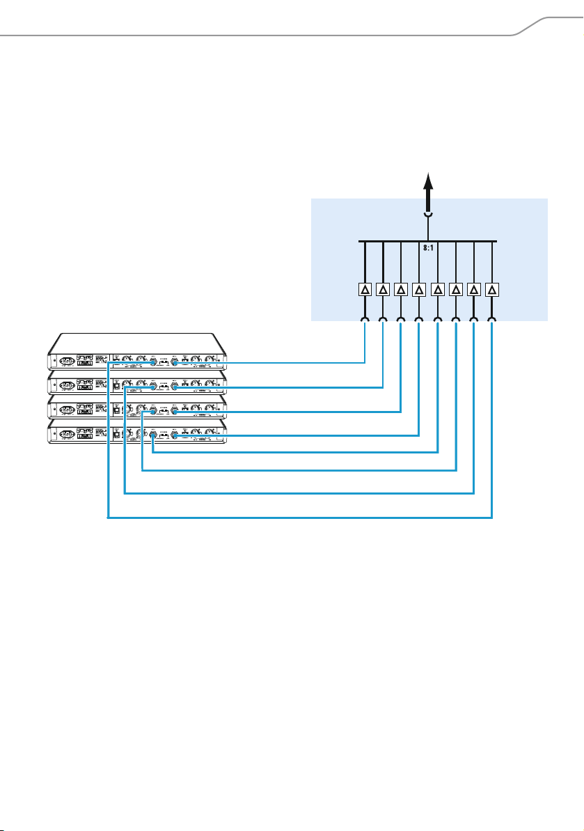
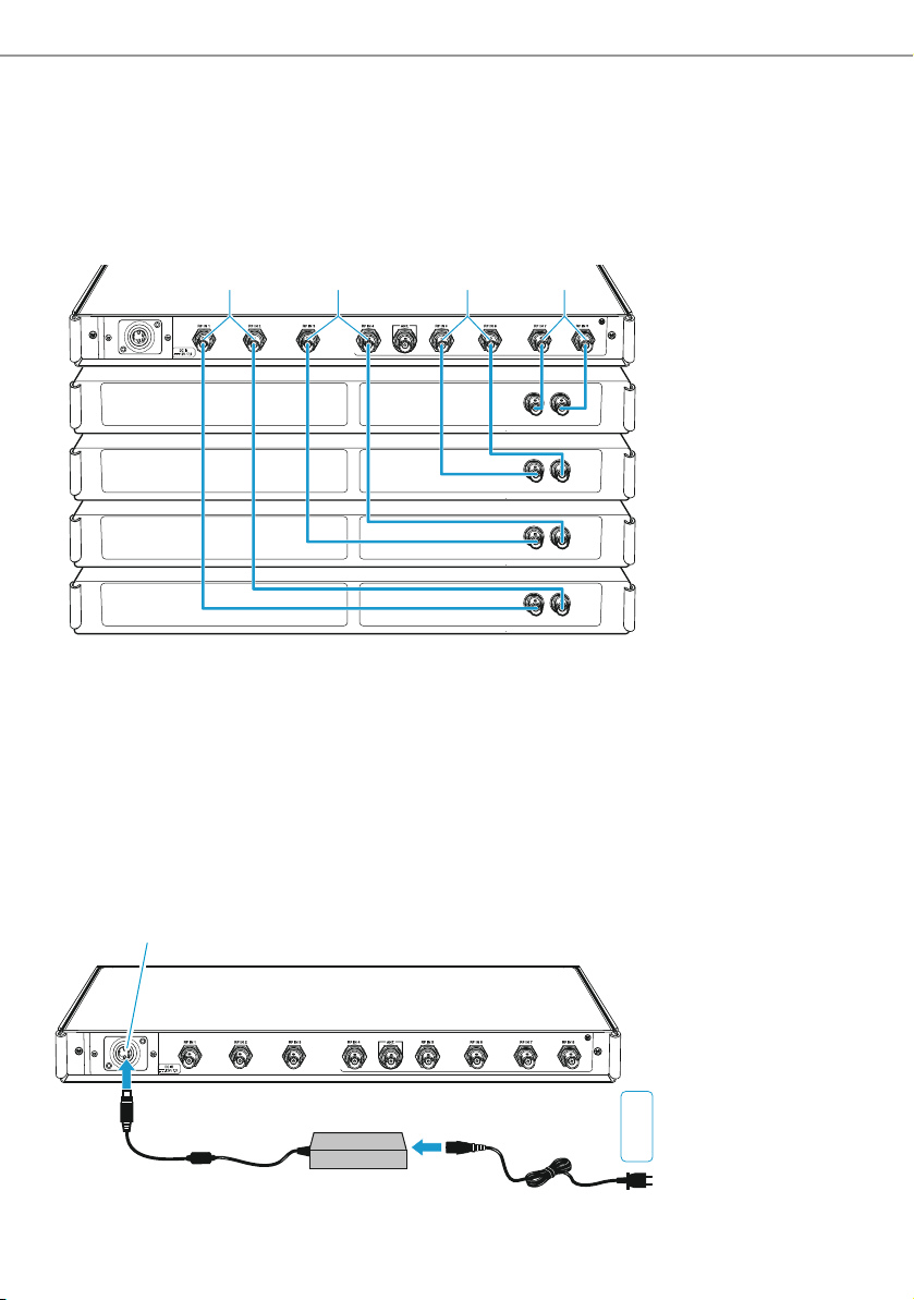
The below connection diagram shows the connections for an 8-channel system with a
single antenna.
AC 3200-II | 5
Page 8
Product overview
77
Product overview
23452
1
ACTIVE TRANSMITTER COMBINER
AC 3200-II
8776
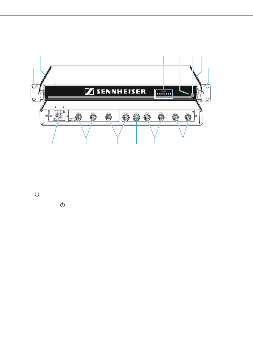
1 Rack mount “ears”
2 Air vents (on the sides)
3 8 LEDs: operation indicators of the RF inputs
4 LED
5 On/off switch
6 DC input socket for connecting the NT 12-125D mains unit
7 8 RF inputs RF IN 1 to RF IN 8 for connecting the transmitters
8 BNC socket for antenna output ANT
1
6 | AC 3200-II
Page 9

Putting the AC 3200-II into operation
Putting the AC 3200-II into operation
Preparing the AC 3200-II for use
You can set up the AC 3200-II on an even surface or mount it into a rack.
Setting up the device
CAUTION
Danger of heat damage to the devices
During op
considerable waste heat. If this heat cannot dissipate, it can cause damage to the
devices.
The devices are equipped with fans to assist dissipation of generated heat:
왘 Make sure that the air vents 2 on the sides of the AC 3200-II are not covered or
bl
air flow between the
왘 Regularly clean the air vents on the sides of the AC 3200-II with a soft brush.
왘 In order to avoid heat accumulation, make sure to install the AC 3200-II as the
up
왘 Never stack more than two devices directly
왘 Never place several NT 12-125D mains units directly next to one another.
eration, the AC 3200-II and the connected transmitters produce
ocked and provide ducts of sufficient size or allow sufficient space to ensure a free
devices.
permost device.
one above the other.
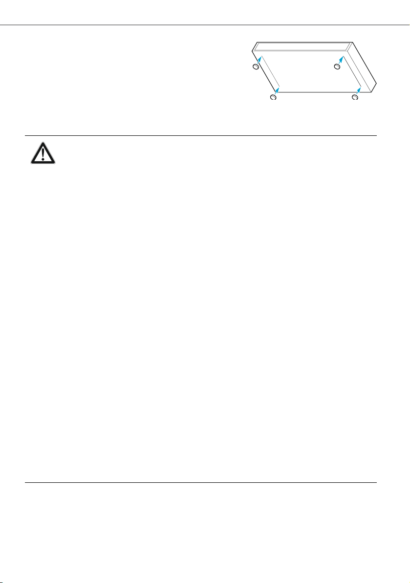
To ensure that the AC 3200-II cannot slip on the surface on which it is placed, four selfadhesive soft rubber feet are supplied.
CAUTION
Risk of staining of surfaces
Som
e surfaces have been treated with varnish, polish or synthetics which might cause
stains when they come into contact with other synthetics. Despite a thorough testing
of the synthetics used by us, we cannot rule out the possibility of staining.
왘 Do not place the AC 3200-II on delicate surfaces.
왘 Ensure that the base of the AC 3200-II is clean and
the rubber feet.
free from grease before fitting
AC 3200-II | 7
Page 10
Putting the AC 3200-II into operation
왘 Fix the rubber feet to the base of the AC 3200-II
peeling off the backing paper and fitting them
by
as shown in the diagram on the right.
왘 Place the AC 3200-II on an even, horizontal
face.
sur
Rack-mounting
CAUTION
Risks when rack mounting
When installing the device in a closed or multi-rack assembly, please consider
that, during operation, the ambient temperature, the mechanical loading and
the electrical potentials will be different from those of devices which are not
mounted into a rack:
왘 The ambient temperature within the rack must not exceed the
rature limit specified in the AC 3200-II specifications.
tempe
왘 When installing the device in a rack, take good care not to affect the
tilation required for safe operation. If necessary, provide additional
ven
ventilation.
왘 In order to avoid heat accumulation, mak
the uppermost device in the rack.
왘 Provide for a duct or vent space of 1 U
the heated air can dissipate.
왘 Never place several NT 12-125D mains units directly next to one another.
왘 Make sure the mechanical loading of the rack is even to avoid a hazardo
condition such as a severely unbalanced rack.
왘 Make sure the two cables of the NT 12
to mechanical loading (e.g. pull
왘 When connecting the device to the power supply, observe the information
indicated on the mains unit. Avoid circuit overloading. If necessary, provide
overcurrent protection.
왘 Ensure a reliable mains ground connection of the device by taking
appropr
strips or extension cables.
iate measures – especially when you are using multi-outlet power
the AC 3200-II
e sure to install the AC 3200-II as
above the AC 3200-II to ensure that
us
-125D mains unit are not exposed
ing).
To mount the AC 3200-II into a 19’’ rack:
왘 Slide the AC 3200-II into the 19’’ rack.
왘 Secure the rack mount “ears” 1 to the rack using four screws (to be ordered
separately
8 | AC 3200-II
).
Page 11
Putting the AC 3200-II into operation
8
Connecting devices
Connecting the antenna
CAUTION
Danger of damage to the devices!
not daisy-chain several AC 3200-II. Do not connect other active combiners to the
Do
AC
3200-II.
왘 Never connect the AC 3200-II to ot
왘 Only connect suitable antennas to the output of the AC 3200-II.
her active combiners.
The AC 3200-II active transmitter combiner can be used with either the A
directional antenna, the A 1031 U omni-directional antenna or the A 5000 CP
circularly polarized UHF antenna. The antenna transmits the signals of all connected
transmitters (see page 11).
The signals are combined onto the antenna output with no distribution attenuation.
To connect an antenna:
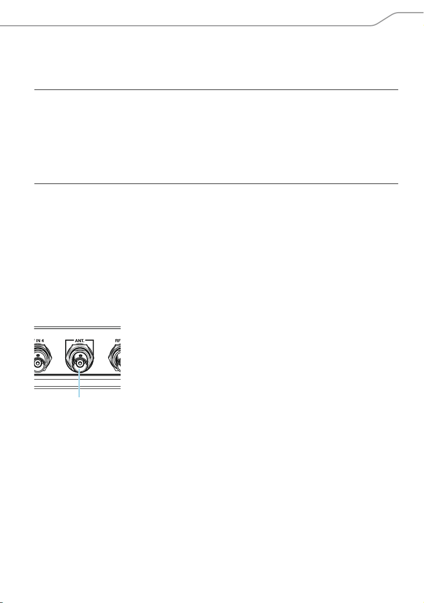
왘 Connect the antenna using a low-attenuation 50-Ω coaxia
왘 Connect the coaxial cable to the antenna output 8.
l cable.
2003 UHF
AC 3200-II | 9
Page 12
Putting the AC 3200-II into operation
77 77
UK
EU
US
6
NT 12-125D
Connecting a transmitter to the AC 3200-II
To connect a transmitter:
왘 Connect the BNC cable of the transmitter to one of the eight RF inputs RF IN 1 to
RF IN 8 7.
Connecting the mains unit
왘 Connect the mains cable (EU, UK or US version, depending on your location) to the
input socket on the NT 12-125D mains unit.
왘 Connect the DC connector of the mains unit to the DC input socket 6 of the
AC 3200-II.
왘 Connect the mains connector of the mains cable to the mains power supply.
10 | AC 3200-II
Page 13
Recommendations and tips for optimum transmission
34
5
Switching the AC 3200-II on and off
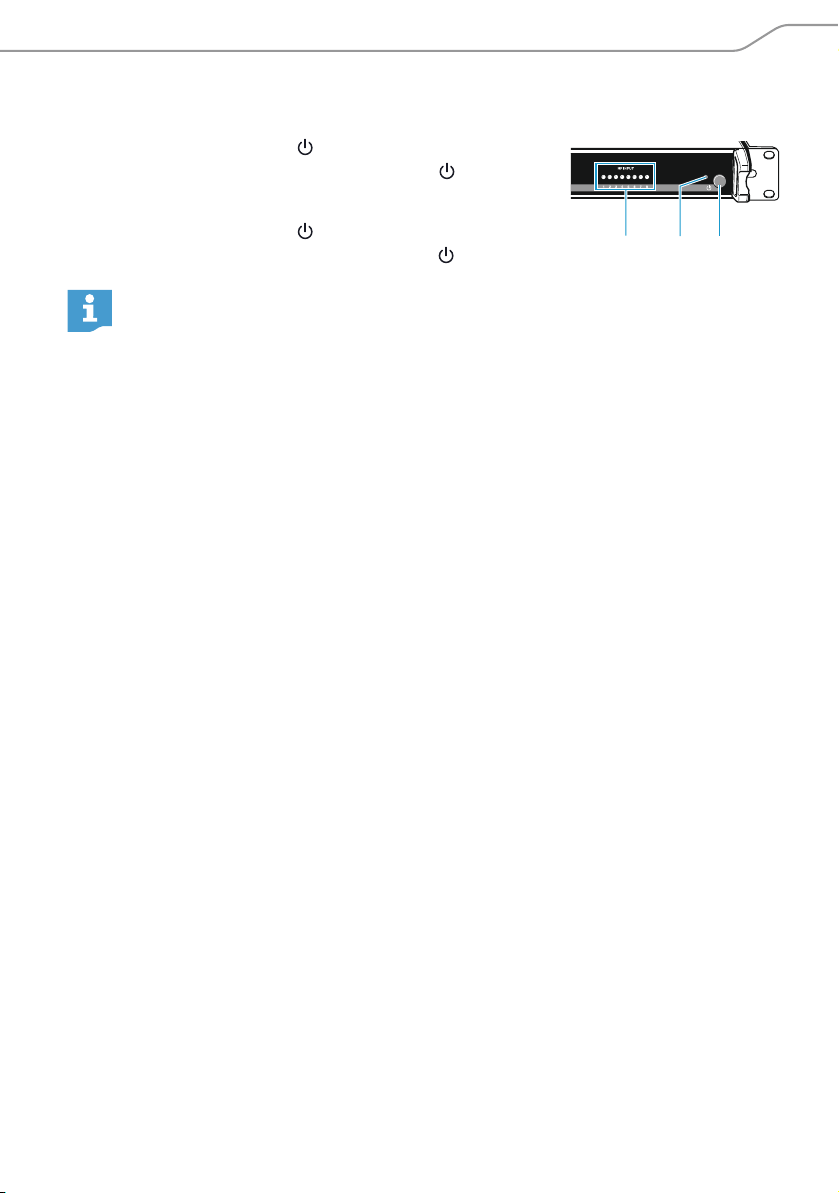
왘 Press the on/off switch 5.
The AC 3200-II switches on and the LED 4 lights up
red.
왘 Press the on/off switch 5 again.
The AC
RF indicators
The AC 3200-II has 8 control LEDs 3 which light up green on the channels where
transmiss
3200-II switches off and the LED 4 goes off.
After switch-off, the AC 3200-II is in standby mode. To disconnect the device
and the NT 12-125D mains unit from the mains power supply, pull out the
mains connector from the wall socket.
ion power is available.
Recommendations and tips for optimum
transmission
• There should be a “free line of sight” between transmitting and receiving
antennas.
• To avoid overloading the receiver, observe a minimum distance of 5 m between
transmitting and receiving antennas.
• Observe a minimum distance of 50 cm between the transmitting antenna and
metal objects (such as cross members or reinforced-concrete walls).
• When using a multi-channel system:
Set all transmitters of your multi-channel system to intermodulation-free
frequencies.
AC 3200-II | 11
Page 14
Cleaning and maintaining the AC 3200-II
Cleaning and maintaining the AC 3200-II
CAUTION
Liquids can damage the electronics of the device
Liquids entering
damage the electronics.
왘 Keep all liquids away from the device.
왘 Do not use any solvents or cleansing agents.
왘 Before cleaning, disconnect the NT 12-125D mains unit from the mains power
supply.
왘 Only use a dry cloth to clean the device.
the housing of the device can cause a short-circuit and
왘 Regularly check the air vents for dust deposi
a soft brush.
ts. If necessary, remove the dust with
If a problem occurs ...
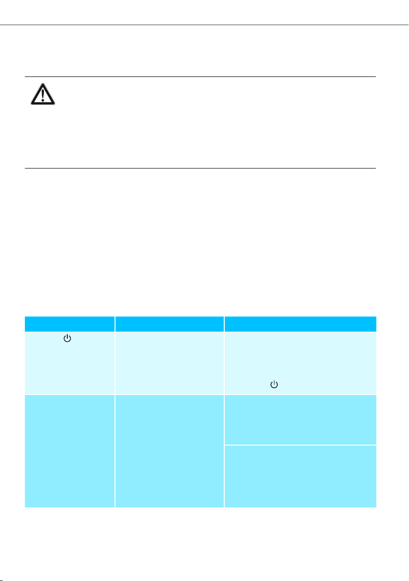
Problem Possible cause Solution
The LED 4 does
not light up
Extra LEDs 3 light
up for RF inputs
which are not in use
The AC 3200-II doesn’t
consume current.
The transmitting
antenna or the antenna
cable is not connected,
of the wrong type,
damaged or faulty
.
Check if the AC 3200-II is connected
to the NT 12-125D mains unit, if
the mains unit is connected to the
mains power supply and if the on/
off switch 5 is pressed.
Check that the transmitting
antenna or the antenna cable is
correctly connected, of the correct
type, and is not damaged or faulty.
Check that the transmitting
antenna or the antenna cable
is connected to the antenna
output 8 and that all transmitters
connected to RF inputs 7.
are
12 | AC 3200-II
Page 15

If a problem occurs ...
Problem Possible cause Solution
One or several
LEDs 3 do not light
up
Disturbed reception
or no reception
A transmitter is
connected to the
corresponding input
but the transmitter
is not switched on.
The transmitting
antenna is not within the
reception area.
The receiver batteries
are not inserted or
batteries are low.
The antenna is not
connected correctly.
Too high cable
attenuation due to too
long antenna cables or
wrong type of antenna
cable.
Interference or
intermodulation during
multi-channel operation.
Switch the transmitter on.
Reduce the distance between
transmitter and receiver.
Replace the receiver batteries.
Check if the antenna is connected
correctly.
Use a shorter antenna cable or the
correct type of antenna cable.
Use low-attenuation 50 Ω coaxial
cable.
Set all transmitters of your
multi-channel system to
intermodulation-free frequencies.
If a problem occurs that is not listed in the above table or if the proble
solved with the proposed solutions, please contact your local Sennheiser partner for
assistance.
To find a Sennheiser partner in your country, search at www.sennheiser.com under
“Service & Support”.
m cannot be
AC 3200-II | 13
Page 16

Specifications
Specifications
AC 3200-II
Frequency range 500 to 870 MHz
D
istribution attenuation 0 dB (±1 dB)
RF input power
Nominal value up to 100 mW per input
Inputs protected up to max. 250 mW
Impedanc
ower supply 12 V
P
Current consumption max. 7.5 A
Power consumption max. 90 W
Temperature range –10°C to +45°C
Weight approx. 4 kg
Dimensions 436 x 215 x 44 mm
e 50 Ω
NT 12-125D
Type Mean Well GTS160A12
Input voltage 100 to 240 V
Input frequency 50 to 60 Hz
Current consumption max. 1.85 A
Output voltage 12 V
Output current max. 11.5 A
Temperature range 0°C to +45°C
Weight approx. 660 g (without mains cable)
Dimensions 175 x 72 x 35 mm
Length of DC output cable approx. 100 cm/39 inch
14 | AC 3200-II
~
Page 17
Manufacturer Declarations
0682
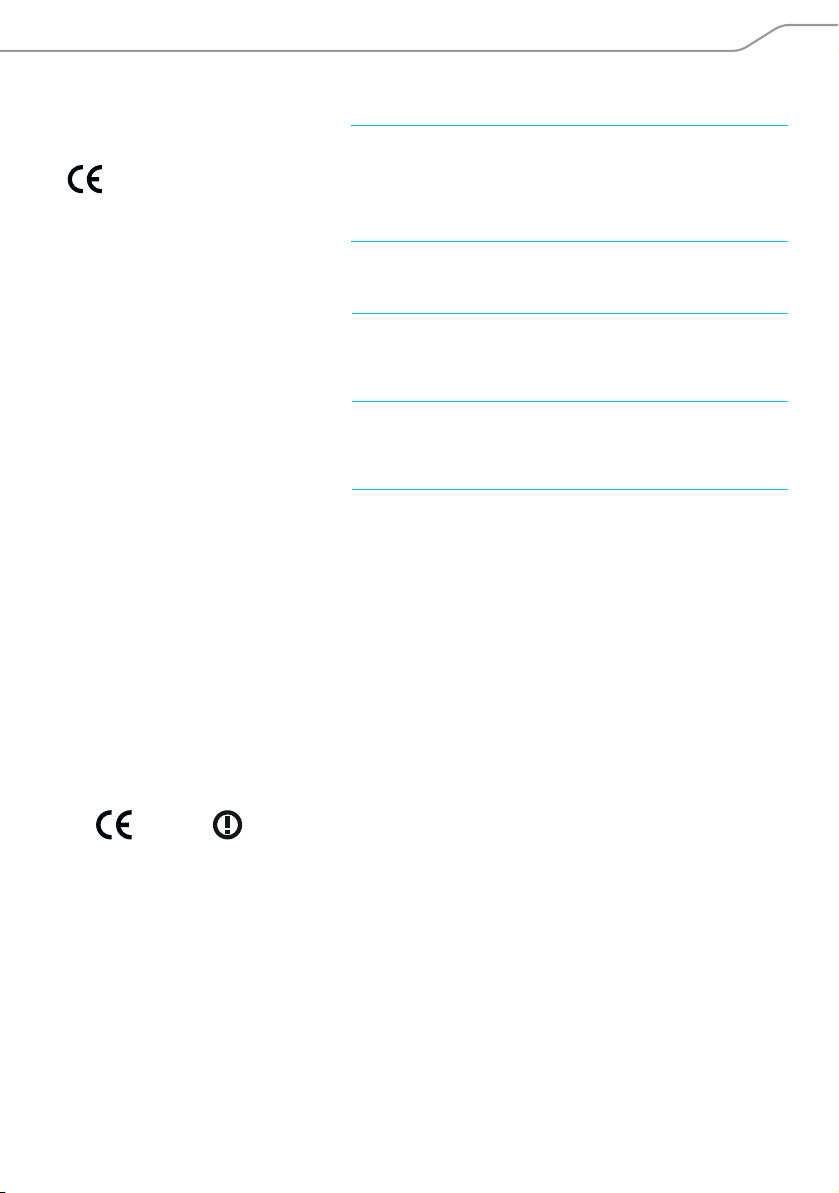
In compliance with
Europe EMC EN 301489-1/-9
Radio EN 300422-1/-2
EN 300454-1/-2
Safety EN 60950
Approved
Canada Industry Canada RSS-123
USA FCC-Part 74
by
IC: 2099A-AC3200A2
limited to 698 MHz
FCC ID: DMOAC3200A2
limited to 698 MHz
Manufacturer Declarations
Warranty
Sennheiser electronic GmbH & Co. KG gives a
For the current warranty conditions, please visit our website at www.sennheiser.com
or contact your Sennheiser partner.
CE Declaration of Conformity
•
warranty of 24 months on this product.
R&TTE Directive (1999/5/EC)
•
• RoHS Directive (2012/65/EC)
The declaration is available on the Internet at www.sennheiser.com/download.
Before putting the device into operation, please observe the respective countryspecific regulations.
AC 3200-II | 15
Page 18

Manufacturer Declarations
Statements regarding FCC and Industry Canada
This device complies with Part 15 of the FCC Rules and with Industry Canada licenceexempt RSS standard(s). Operation is subject to the following two conditions: (1) this
device may not cause harmful interference, and (2) this device must accept any
interference received, including interference that may cause undesired operation.
This equipment has been tested and found to comply with the limits for a Class B
digital device, pursuant to Part 15 of the FCC Rules. These limits are designed to
provide reasonable protection against harmful interference in a residential
installation. This equipment generates, uses and can radiate radio frequency energy
and, if not installed and used in accordance with the instructions, may cause harmful
interference to radio communications. However, there is no guarantee that
interference will not occur in a particular installation. If this equipment does cause
harmful interference to radio or television reception, which can be determined by
turning the equipment off and on, the user is encouraged to try to correct the
interference by one or more of the following measures:
• Reorient or relocate the receiving antenna.
• Increase the separation between the equipment and receiver.
• Connect the equipment into an outlet on a circuit different from that to which the
receiver is connected.
• Consult the dealer or an experienced radio/TV technician for help.
Changes or modifications made to this equipment not expressly approved by
Sennheiser electronic Corp. may void the FCC authorization to operate this equipment.
Before putting the device into operation, please observe the respective countryspecific regulations!
16 | AC 3200-II
Page 19

Page 20

Sennheiser electronic GmbH & Co. KG
Am Labor 1, 30900 Wedemark, Germany
www.sennheiser.com
Publ.
09/16, 538976/A02
 Loading...