

Page 1
Questions? Comments? call SENCO's toll-free Action-line: 1-800-543-4596 or e-mail: toolprof@senco.com
PC0968
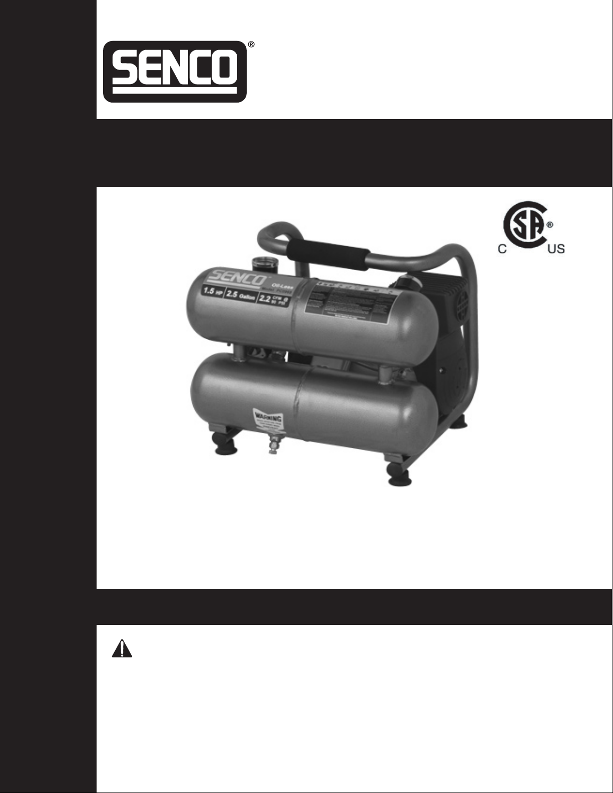
Electric Air Compressor
Senco Products, Inc.
8485 Broadwell Rd.
Cincinnati, OH 45244
Operating Instructions
Warnings for the safe use of this compressor are included in this manual.
Des mises en garde pour une utilisation en toute sécurité de ce compresseur
sont incluses dans ce manuel.
En este manual se incluyen avisos para el uso seguro de este compresor.
© 2003 by Senco Products, Inc.
PC0968 Revised July 31, 2003
(Replaces 6/30/03)
1
Page 2

TABLE OF CONTENTS
INTRODUCTION ................................................................... 3
SAFETY ALER
INSPECTION .........................................................................
SAFETY
ELECTRICAL ................................................................ 4
EXPLOSION OR FIRE..................................................
BURSTING ...................................................................
BREATHING .................................................................
BURNS .........................................................................
FLYING OBJECTS ........................................................
MOVING PARTS........................................................... 7
NEGLIGENCE ..............................................................
AIR COMPRESSOR DAMAGE..................................... 7
COMPRESSOR FEATURES .................................................
PREPARATION.................................................................... 10
INITIAL SET-UP ......................................................... 10
LOCATION .................................................................. 10
ELECTRICAL .............................................................. 10
OPERATION........................................................................ 11
PRE-ST
START-UP .................................................................. 11
SHUTDOWN .............................................................. 11
T..................................................................... 3
WARNINGS ............................................................ 4
ART CHECKLIST ........................................... 11
3
5
5
6
6
6
7
8
MAINTENANCE................................................................... 11
TROUBLESHOOTING ................................................... 12-14
SPECIFICATIONS ............................................................... 15
WARRANTY ........................................................................ 16
2
Page 3
3
INTRODUCTION
Congratulations on the purchase of your new SENCO® Air Compressor! You can be assured your SENCO Air
Compressor was constructed with the highest level of precision and accuracy. Each component has been rigorously
tested by technicians to ensure the quality, endurance and performance of this air compressor.
This operator’s manual was compiled for your benefit. By reading and following the simple safety, installation and
operation, and maintenance steps described in this manual, you will receive years of troublefree
operation
from your new SENCO Air Compressor. . The contents of this manual are based on the latest product
information available at the time of publication. The manufacturer reserves the right to make changes in price,
color, materials equipment, specifications or models at any time without notice.
SAFETY ALERT!
A ”
DANGER, WARNING or CAUTION
” safety warning will be surrounded by a ”SAFETY ALERT BOX”.
This box is used to designate and emphasize Safety Warnings that must be followed when operating this
air compressor. Accompanying the safety warnings are “Signal Words” which designate the degree or
level of hazard seriousness. The “Signal
Words” used in this manual are as follows:
DANGER:
Indicates an imminently hazardous situation which, if not avoided,
WILL result in
death or serious injury
.
WARNING:
Indicates a potentially hazardous situation which, if not avoided,
COULD result in death or serious injury.
CAUTION:
Indicates a potentially hazardous situation which, if not avoided
MAY result in
minor or moderate injury or damage to the air
compressor
.
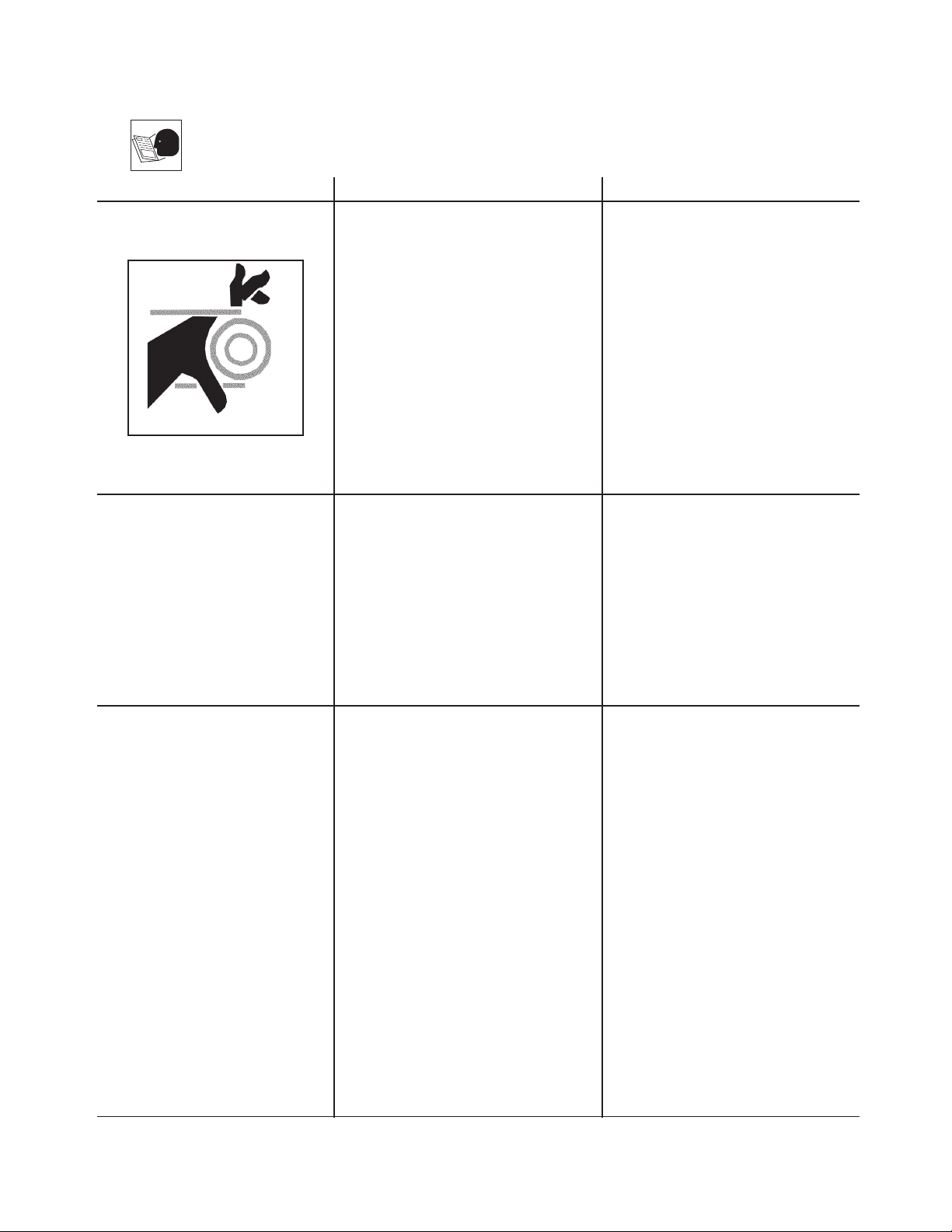
The symbols set to the left of this paragraph are “Safety Alert Symbols”.
These symbols are used to call attention to items or procedures that could
be dangerous to you or other persons using this equipment.
ALWAYS PROVIDE A COPY OF THIS MANUAL
TO ANYONE USING THIS EQUIPMENT. READ ALL
INSTRUCTIONS IN THIS MANUAL AND ANY INSTRUCTIONS SUPPLIED BY MANUFACTURERS OF
SUPPORTING EQUIPMENT BEFORE OPERATING THIS AIR COMPRESSOR AND ESPECIALLY POINT OUT
THE “SAFETY
WARNINGS” TO PREVENT THE POSSIBILITY OF PERSONAL INJURY TO THE OPERATOR.
INSPECTION
Unbox the air compressor and write in the serial number in the space provided below. Inspect for signs of obvious
or concealed freight damage. Be sure that all damaged parts are replaced and any mechanical problems are
corrected prior to the operation of the air compressor.
SERIAL NUMBER__________________________________________
If you have Questions or Comments call SENCO’s
toll-free Action-line: 1-800-543-4596 or, e-mail:
toolprof@Senco.com
Please have the following information available for all service calls:
1. Model Number
2. Serial Number
3. Date and Place of Purchase
Senco, 8485 Broadwell Road, Cincinnati, OH 45244
Page 4
SAFETY WARNINGS
READ ALL SAFETY WARNINGS BEFORE USING AIR COMPRESSOR
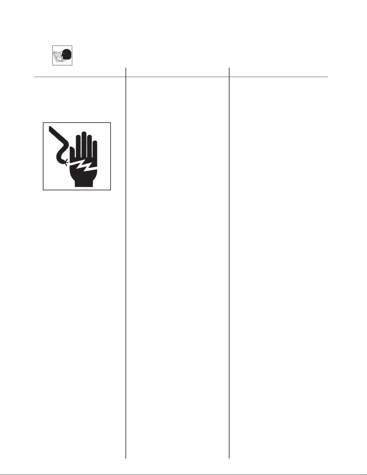
HAZARD
RISK OF
ELECTRIC SHOCK
OR
ELECTROCUTION
POTENTIAL CONSEQUENCE
Serious injury or death could occur if
the air compressor is not properly
grounded.
powered by electricity and may cause
electric shock or electrocution if not
used properly
Electrical shock may occur from
electrical cord.
Electrical shock may occur if air
compressor is not operated properly.
Your air compressor is
.
PREVENTION
Make sure the air compressor is
plugged into a properly grounded
outlet which provides correct
voltage and adequate fuse
protection.
Check power cord for signs of
crushing, cutting or heat damage.
Replace faulty cord before use.
Keep all connections dry and off the
ground. Do not allow electrical
cords to lay in water or in such a
position where water could come in
contact with them. Do not touch
plug with wet hands.
Do not pull on the electrical cord to
disconnect from the outlet.
Never operate air compressor in
wet conditions or outdoors when it
is raining.
Serious injury or death may occur if
electrical repairs are attempted by
unqualified persons.
Never operate air compressor with
safety guards/covers removed or
damaged.
Any electrical wiring or repairs
performed on this air compressor
should be done by Authorized
Service Personnel in accordance
with National and Local electrical
codes.
Before opening any electrical
enclosure, always shut off the air
compressor, relieve pressure and
unplug the air compressor from the
power source. Allow air compressor
to cool down. Never assume the air
compressor is safe to work on just
because it is not operating. It could
restart at any time!
4
Page 5

5
SAFETY WARNINGS
READ ALL SAFETY WARNINGS BEFORE USING AIR COMPRESSOR
POTENTIAL CONSEQUENCE
Serious injury or death may occur from
normal electrical sparks in motor and
pressure switch.
Serious injury may occur if any air
compressor ventilation openings are
restricted, causing the air compressor
to overheat and start on fire.
Serious injury or death may occur from
an air tank explosion if air tanks are
not properly maintained.
Serious injury may occur from an air
compressor malfunction or exploding
accessories if incorrect system
components, attachments or
accessories are used.
HAZARD
RISK OF
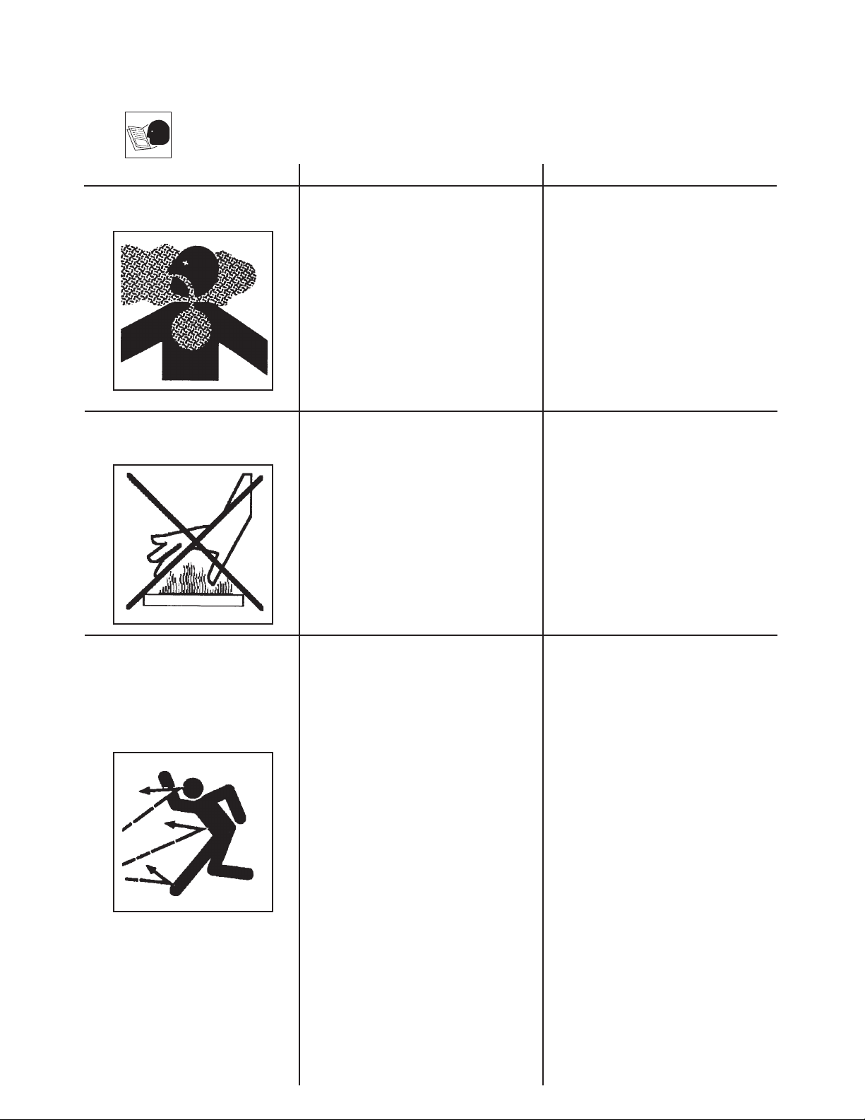
EXPLOSION OR FIRE
RISK OF
BURSTING
PREVENTION
Always operate air compressor in a
well ventilated area free of
flammable vapors, combustible
dust, gases or other combustible
materials.
If spraying flammable material,
locate the air compressor at least
20 feet away from the spray area.
(An additional hose may be
required.)
Never place objects against or on
top of air compressor. Operate air
compressor at least 12 inches away
from any wall or obstruction that
would restrict proper ventilation.
Drain air tank daily or after each use
to prevent moisture buildup in the
air tank.
If air tank develops a leak, replace
the air tank immediately. Never
repair, weld or make modifications
to the air tank or its attachments.
Never make adjustments to the
factory set pressures.
Never exceed manufacturers
maximum allowable pressure rating
of attachments.
Because of extreme heat, do not
use plastic pipe or lead tin soldered
joints for a discharge line.
Never use air compressor to inflate
small, low pressure objects such as
toys.
Page 6
SAFETY WARNINGS
READ ALL SAFETY WARNINGS BEFORE USING AIR COMPRESSOR
HAZARD
RISK TO
BREATHING
RISK OF
BURNS
POTENTIAL CONSEQUENCE
Serious injury or death could occur
from inhaling compressed air. The air
stream may contain carbon monoxide,
toxic vapors or solid particles.
Sprayed materials such as paint, paint
solvents, paint remover, insecticides,
weed killers, etc. contain harmful
vapors and poisons.
Serious injury could occur from
touching exposed metal parts.
These areas can remain hot for some
time after the air compressor is
shutdown.
PREVENTION
Never inhale air from the air
compressor either directly or from
breathing device connected to the air
compressor
Operate air compressor only in a well
ventilated area. Follow all safety
instructions provided with the
materials you are spraying. Use of a
respirator may be required when
working with some materials.
Never allow any part of your body or
other materials to make contact with
any exposed metal parts on the air
compressor
.
.
a
RISK
OF FLYING
OBJECTS
Soft tissue damage can occur from the
compressed air stream.
Serious injury can occur from loose
debris being propelled at a high speed
from the compressed air stream.
Always wear OSHA required “Z87”
safety glasses to shield the eyes
from flying debris.
Never point the air stream at any part
of your body, anyone else or animals.
Never leave pressurized air
compressor unattended. Shut off air
compressor and relieve pressure
before attempting maintenance,
attaching tools or accessories.
Always maintain a safe distance from
people and animals while operating
the air compressor.
Do not move the air compressor
while air tank is under pressure. Do
not attempt to move the air
compressor by pulling on the hose.
6
Page 7
7
POTENTIAL CONSEQUENCE
Risk of bodily injury from moving parts.
This air compressor cycles
automatically when the pressure
switch is in the “On/Auto” position.
Risk of injury from negligent use.
Risk of major repair
.
SAFETY WARNINGS
READ ALL SAFETY WARNINGS BEFORE USING AIR COMPRESSOR
RISK FROM
NEGLIGENCE
RISK
OF AIR COMPRESSOR
DAMAGE
HAZARD
RISK FROM
MOVING PARTS
PREVENTION
Always turn off air compressor when
not in use. Bleed pressure from the
air hose and unplug from electrical
outlet before performing
maintenance. All repairs to the air
compressor should be made by an
Authorized Service person. Never
assume the air compressor is safe
to work on just because it is not
operating. It could restart at any time!
Do not operate without protective
covers/guards. Replace damaged
covers/guards before using the air
compressor
.
Never allow children or adolescents
to operate this air compressor!
Stay alert-watch what you are doing.
Do not operate the air compressor
when fatigued or under the influence
of alcohol or drugs.
Know how to stop the air
compressor. Be thoroughly familiar
with controls.
Do not operate air compressor
without an air filter.
Do not operate air compressor in a
corrosive environment.
Always operate the air compressor
in a stable, secure position to prevent
air compressor from falling.
Follow all maintenance instructions
listed in this manual.
! SAVE THESE INSTRUCTIONS !
Page 8
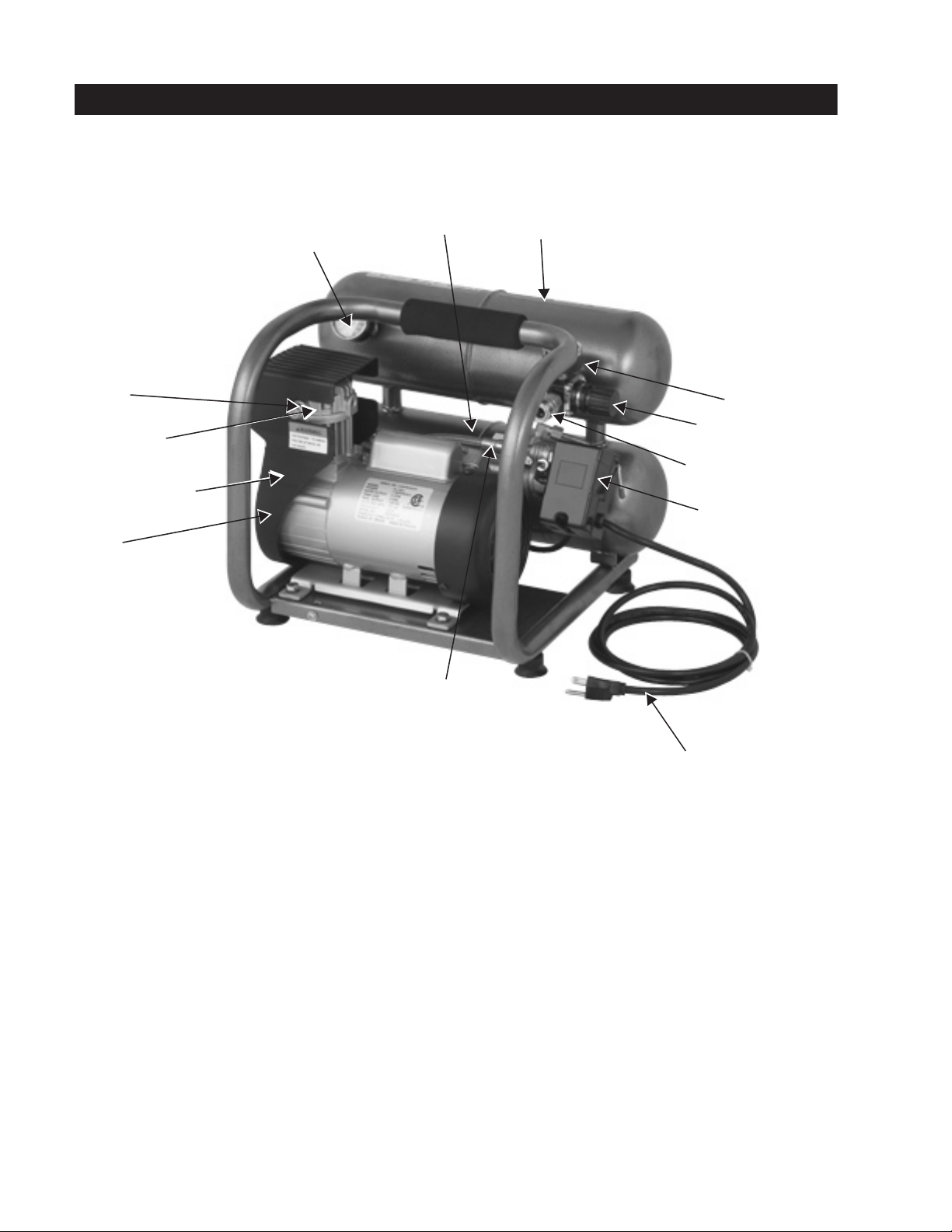
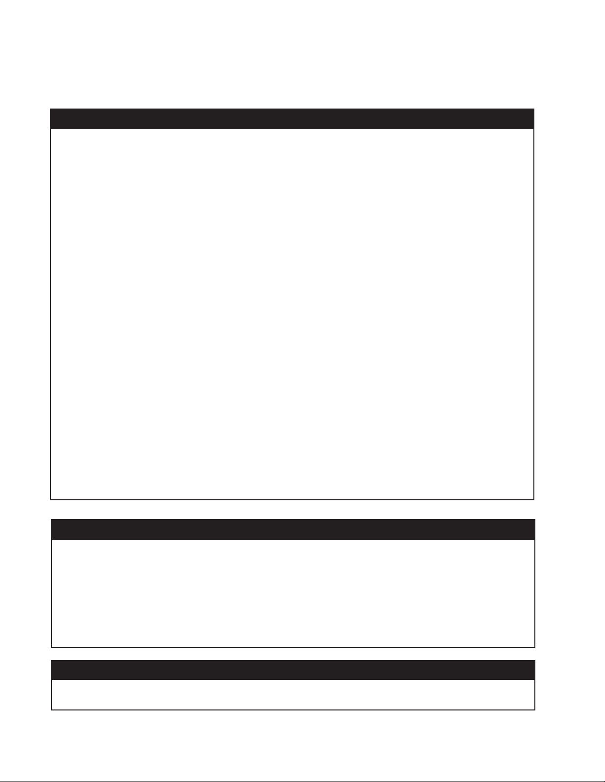
COMPRESSOR FEATURES
13
11
4
3
12
5
6
2
10
9
1
1 Motor/Pressure Switch
Air Compressor Pump
2
Safety Relief
3
Tank Pressure Gauge
4
5
Outlet Pressure Gauge
6
Pressure Regulator
7
Discharge Line
8
9
10
11
12
13
Volt Electric Power Cord
115
Ventilation Openings/Protective Shroud
Quick Disconnect
Air Filter
Tank Drain
Cold Start Valve
V
alve
7
8
8
Page 9

COMPRESSOR FEATURES
1) MOTOR/PRESSURE SWITCH: This switch is used to start or stop the air
compressor. Moving the switch to the Auto (On) position will provide automatic
power to the pressure switch which will allow the motor to start when the air tank
pressure is below the factory set cut-in pressure. When in the Start/ Stop Option,
the pressure switch stops the motor when the air tank pressure reaches the factor
set cut-out pressure. For safety purposes, this switch also has a pressure release
valve located on the side of the switch designed to automatically release compressed
air from the air compressor pump head and its discharge line when the air compressor
reaches cut-out pressure or is shut off.
the switch to the Off position will remove power from the pressure switch and stop
the air compressor.
2)
MOTOR THERMAL OVERLOAD: The electric motor has a thermal
overload protector. If the motor overheats for any reason, the thermal overload will
cut off power, thus preventing the motor from being damaged. Wait until the motor is
cool. Motor also has a magnetic breaker. Reset switch if it is tripped.
3) AIR INTAKE FILTER: This filter is designed to clean air coming into the pump. To
ensure the pump continually receives a clean, cool, dry air supply this filter must
always be clean and ventilation opening free from obstructions. The filter can be
removed for cleaning by using warm, soapy water. Rinse the filter and air dry.
4) AIR COMPRESSOR PUMP: To compress air, the piston moves up and down in
the cylinder. On the downstroke, air is drawn in through the air intake valve while
the exhaust valve remains closed. On the upstroke, air is compressed, the intake
valve closes and compressed air is forced out through the exhaust valve, into the
discharge line, through the check valve and into the air tank.
This allows the motor to restart freely. Moving
1
2
3
5) SAFETY RELIEF VA
relieving pressure from the system when the compressed air reaches a predetermined
level. The valve is preset by the manufacturer and must not be modified in any way
To
verify the valve is working properly, pull on the ring. Air pressure should escape.
When the ring is released, it will reseat.
6) AIR TANK DRAIN VALVE: The drain valve is used to remove moisture from the air
tank(s) after the air compressor is shut off.
when more than 10 PSI of air pressure is in the air tank! To open the drain valve,
turn the knob counterclockwise. Tilt tank to ensure that all condensation drains
through valve.
7) AIR TANK PRESSURE GAUGE: The air tank pressure gauge indicates the
reserve air pressure in the air tank (s).
8) OUTLET PRESSURE GAUGE: The outlet pressure gauge indicates the air
pressure available at the outlet side of the regulator. This pressure is controlled
by the regulator and is always less or equal to the air tank pressure.
9) PRESSURE REGULA
controlled by the regulator knob. Turn the pressure regulation knob clockwise to
increase discharge pressure, and counterclockwise to decrease discharge
pressure.
LVE: This valve is designed to prevent system failures by
NEVER attempt to open the drain valve
TOR: The air pressure coming from the air tank is
5
.
6
7
8
9
10
10) DISCHARGE LINE: Please note that the discharge line is very hot.
9
Page 10
10
PREPARATION
INITIAL SET-UP:
1.
Read safety warnings before setting-up air compressor
.
LOCATION:
CAUTION
In order to avoid damaging the air compressor, do not incline the air compressor
transversely or longitudinally more than 10°.
1. Place air compressor at least 12 inches away from obstacles that may prevent proper ventilation.
Do not place air compressor in an area:
-where there is evidence of oil or gas leaks.
-where flammable gas vapors or materials may be present.
WARNING
Serious injury or death may occur if electrical sparks from motor and pressure switch
come in contact with flammable vapors, combustible dust, gases or other
combustible materials. When using the air compressor for spray painting, place the
air compressor as far away I from the work area as possible, using extra air hoses instead of
extension cords.
-where air temperatures fall below 32°F or exceed 104°F.
-where extremely dirty air or water could be drawn into the air compressor.
ELECTRICAL:
DANGER
Improper connection of the equipment-grounding conductor can result in a risk
of shock or electrocution. Check with a qualified electrician or service personnel
if you are in doubt as to whether the outlet is properly grounded. Do not use any type of
adapter with this product. If repair or replacement of the cord or plug is necessary, do not
connect the grounding wire to either flat blade terminal. The wire with insulation having
an outer surface that is green with or without yellow stripes is the grounding wire.
WARNING
This product must be grounded. If there should be a malfunction or breakdown,
grounding
provides a path of least resistance for electric current to reduce the
risk of electric shock. This product is equipped with a cord having an equipmentgrounding conductor and a grounding type plug. The plug must be plugged into an
appropriate outlet that is properly installed and grounded in accordance with all local
codes and ordinances.
1. SENCO® DOES NOT RECOMMEND THE USE OF EXTENSION CORDS as this can create power loss and
overheating of the motor. Use of an additional air hose is recommended rather than an extension cord. If use of an
extension cord is unavoidable, it should be plugged into a GFCI found in circuit boxes or protected receptacles.
When using an extension cord, observe the following:
Cable Length Wire Gauge
Up to 25 feet 12 AWG
Up to 100 feet 10 AWG
Up to 150 feet 8 AWG
Up to 250 feet 6 AWG
Use only 3-blade extension cords that have 3-blade grounding-type plugs and 3-slot cord connectors that will
accept the plug from the product. Use only extension cords having an electrical rating not less than the rating of
the product. Do not use damaged extension cords. Examine extension cord before using and replace if damaged.
Do not abuse extension cord and do not yank on any cord to disconnect. Keep cord away from heat and sharp
edges. Always shut off the air compressor switch before removing the plug from the receptacle.
Page 11
11
OPERATION
PRE-START CHECKLIST:
1. Remove any moisture in the air compressor air tank. Remove excessive pressure with an air tool, then open
the air tank drain valve in the bottom of the air tank. Close tightly when drained.
WARNING: Risk of bodily injury. NEVER attempt to open the drain valve when
more than 10 PSI of air pressure is in the air tank!
2. Make sure the air compressor Motor Switch is in the “OFF” position.
3.
Make sure all safety valves are working correctly.
4.
Make sure all guards and covers are in place and securely mounted.
START-UP:
1.
Ensure the lever on the pressure switch box is in the “OFF” position.
2.
Plug the power cord into a grounded outlet.
3. Move the lever on the pressure switch box to the “AUTO” position.
4. START/STOP OPTION:
Turn it to the ON
position.
This will allow the air compressor
to “START” building
up pressure in the air tanks and “STOP” when correct pressure is achieved. When pressure
drops with usage,
the air compressor will “START” building up pressure again.
5. Set pressure by adjusting the pressure regulator knob counterclockwise for less pressure and clockwise for
more pressure.
6.
If you notice any unusual noise or vibration, stop the air compressor and refer to “Troubleshooting”.
SHUTDOWN:
1. To stop the air compressor, move the lever on the pressure switch box to the “OFF” position. NEVER stop the
air compressor by unplugging it from the power source. This could result in risk of electrocution.
2. Drain air from the air tank by releasing air with an attached air tool or by pulling on the safety relief valve ring.
3. Once pressure in the air tanks register under 10 pounds, open the drain valve under each air tank to drain any
moisture.
4.
Allow the air compressor to cool down.
5.
Wipe air compressor clean and store in a safe, non-freezing area.
MAINTENANCE
Read the instruction manual before performing maintenance. The following procedures must be performed when
stopping the air compressor for maintenance or service.
1.
Turn off air compressor.
WARNING: Never assume the air compressor is safe to work on just because it is not
operating. It could restart at any time!
2. Disconnect cord from main power supply.
3.
Open all drains.
4.
Wait for the air compressor to cool before starting service.
MAINTENANCE CHART
PROCEDURE DAILY WEEKLY MONTHLY
Drain condensation in air tank(s) X
Check for unusual noise/vibration X
Check for air leaks X
Inspect air filter
X
Clean exterior of compressor
X
Check safety relief valve
X
Page 12
12
TROUBLESHOOTING
Symptom 1. Motor will not run or restart.
Power cord not plugged in.
Motor/Pressure switch in “OFF” position.
Motor thermal overload switch has
tripped.
Fuse blown or circuit breaker has tripped.
Wrong gauge wire or length of extension
cord.
Air tank pressure exceeds motor/
pressure switch “cut-in” pressure.
Pressure release valve on motor/
pressure switch has not unloaded pump
head pressure.
Defective motor, motor capacitor, motor/
pressure switch, or check valve.
Plug
cord into grounded outlet.
Move switch to “ON”
position.
Turn air compressor off, wait until motor is cool, then check
motor circuit breaker.
Replace
fuse or reset circuit breaker.
Check for proper fuse amperage.
Check
for low voltage conditions.
Disconnect any other electrical appliances from circuit or
operate air compressor on its own branch circuit.
Check chart on page #10 for proper gauge wire and cord length.
Motor
will start automatically when air tank pressure drops
below
“cut-in” pressure of motor/pressure switch.
Bleed
the line by moving the switch to the “Off” position.
Contact
Senco Customer Service.
PROBABLE CAUSE
Motor/Pressure switch does not shut off motor when
air compressor reaches “cut-out” pressure and safety
relief valve activates.
Air compressor is incorrectly sized.
PROBABLE CAUSE
Defective pilot valve, the check valve is stuck open.
REMEDY
Move the motor/pressure switch to the “Off” position. If
the motor doesn’t shut off, unplug the air compressor. If
the electrical contacts are welded together, replace the
pressure switch.
Limit the air pressure to the capacity of the air
compressor. Either use a smaller tool or a larger air
compressor
.
REMEDY
Remove, clean or replace.
Symptom 2. When in the Start/Stop option, motor runs continuously.
Symptom 3. Air continues to leak at motor/pressure switch release valve after motor stops.
Page 13
13
PROBABLE CAUSE
Defective motor/pressure switch.
PROBABLE CAUSE
Possible defective safety relief valve.
Excessive air tank pressure.
PROBABLE CAUSE
Fittings are not tight enough.
PROBABLE CAUSE
Defective or rusted air tank.
PROBABLE CAUSE
Damaged inlet (reed) valve.
TROUBLESHOOTING
REMEDY
Replace.
REMEDY
Operate safety relief valve manually by pulling on ring.
If it still leaks, it should be replaced.
Defective motor/pressure switch. Replace.
REMEDY
Tighten fittings where air can be heard escaping. Check
fittings with soapy water solution. Do not overtighten.
REMEDY
Air tank must be replaced. Do not attempt to repair
air tank!
REMEDY
Contact SENCO Customer Service 888-222-8144.
Symptom 4. Air continues to leak at motor/pressure switch release valve while motor is running.
Symptom 5. Air leaks from safety relief valve.
Symptom 6. Air leaks at fittings.
Symptom 7. Air leak in air tank.
Symptom 8. Air blowing from inlet filter
.
PROBABLE CAUSE
Pressure regulator knob not turned to high enough
pressure or defective pressure regulator.
Restricted air intake filter.
Air leaks.
Air compressor is not large enough for air
requirement.
REMEDY
Adjust pressure regulator knob to proper setting or
replace.
Clean.
Check for leaks and repair.
Check the accessory air requirement. If it is higher than
the CFM or pressure supply of the air compressor, you
need a larger air compressor.
Symptom 9. Insufficient pressure at air tool or accessory.
Page 14

TROUBLESHOOTING
Symptom 10. Air compressor not making enough air.
PROBABLE CAUSE
Restricted air intake filter.
Defective (reed) valve.
Symptom 11. Moisture in discharge air.
PROBABLE CAUSE
Condensation in air tank caused by high level
of atmospheric humidity or air compressor is
not run long enough.
REMEDY
Clean.
Drain air tank and measure pump up time. Compare to
specifications. If lower, remove pump head and inspect
valve plate, clean or replace.
REMEDY
Drain air tank after every use. Drain air tank more often
in humid weather and use an air line filter.
14
Page 15
15
SPECIFICATIONS
Model # PC0968
Motor
Horsepower 1.5 (Peak)
Voltage 115
Amperage 8
Hz. 60
Phase Single
RPM 3450
Compressor Pump
Number of Cylinders 1
Compression Stage 1
Lubrication Lubeless
Crankcase Aluminum
Bearings Ball
Cylinder Aluminum/Steel Sleeve
Valves Reed-Single
Head Aluminum
Filter Insert
Motor/Pressure Switch Setting
Cut-out 120 PSI
Cut-in 90 PSI
Controls On/Off
Air tank
Capacity 2 gallon
Performance
CFM Air Displacement
4
CFM @ 90 PSI 2.2
Maximum Pressure 120 PSI
Pump-up Time: 0-125 PSI 68 sec.
Recovery Time: 90-120 PSI 15 seconds
Weight
Net 38 Ibs.
Dimensions
Basic LxWxH 16"x15"x13.5"
Page 16

SENCO COMPRESSOR AND P
This compressor has been designed and constructed using the highest standards of material and workmanship.
ARTS W
ARRANTY
COMPRESSOR
The length of this guarantee is one year
Senco Products, Inc., will repair or replace at Sencoís option, any original part or parts for the original retail purchaser. This will
be done free of charge, provided the parts are determined defective in materials or workmanship upon examination by a Senco
Authorized
carry a warranty for the balance of the period of warranty applicable to the part it replaces. When repair or replacement of parts
or compressor is necessary, the original retail purchaser returns the complete compressor or part, with transportation prepaid,
to the nearest Senco Authorized
is within the warranty period.
Senco warrants all parts (except those listed below) of your Senco air compressor to be free from defects in materials and
workmanship during the following periods:
1. For 1 year from date of original purchase:
2. For 90 days from date of original purchase:
Defective parts not subject to normal wear and tear will be repaired or replaced, at our (Sencoís) option, during warranty period.
In any event, reimbursement is limited to the purchase price paid.
EXCLUSIONS:
1. Engine/Motor is covered under separate warranty by its respective manufacturer and is subject to the terms set forth
therein.
2. Normal wear parts not covered under warranty:
3. This warranty does not cover parts damaged due to normal wear,
than recommended speeds or voltage (electric units only), improper storage, or damages resulting during shipping.
4.
Deviation from operating instructions, specifications, and maintenance schedules.
5. Labor charges, loss or damage resulting from improper operation, maintenance or repairs made by person(s) other than
a Senco Authorized Warranty Service Center.
6. The use of other than genuine Senco Repair Parts will void warranty.
WARRANTY:
Warranty Service Center, with the exceptions and exclusions described below. Any replacement part provided will
Warranty Service Center, with purchase receipt or other positive proof that the part or compressor
Compressor Pump Pilot
Tank Assembly Plumbing
Flywheel Throttle Control
Power Cord
Pressure Gauge Pressure Relief
Valve Draincocks
Isolators Drive Belt
Air Filter
from date of purchase by the original retail purchaser. During this period,
Valve
misapplication, misuse, accidents, operation at other
This warranty is contingent upon proper use of the compressor by purchaser and does not cover:
THIS
ORAL, WRITTEN, EXPRESS, OR IMPLIED, INCLUDING, BUT NOT LIMITED
MERCHANTABILITY OR FITNESS FOR A PARTICULAR PURPOSE, ARE EXCLUDED. BUYERíS OR USERíS REMEDIES
ARE SOLELY AND EXCLUSIVELY AS STATED ABOVE. SENCO PRODUCTS, INC. SHALL IN NO EVENT BE LIABLE FOR
INCIDENTAL, CONSEQUENTIAL, INDIRECT, OR SPECIAL DAMAGES. IN NO EVENT, WHETHER AS A RESULT OF A
BREACH OF CONTRACT, WARRANTY, TORT (INCLUDING NEGLIGENCE) OR OTHERWISE, SHALL SENCOíS LIABILITY
EXCEED THE PRICE OF THE COMPRESSOR WHICH HAS GIVEN RISE TO THE CLAIM OR LIABILITY. ANY LIABILITY
CONNECTED WITH THE USE OF THIS COMPRESSOR SHALL TERMINATE UPON THE EXPIRATION OF THE
PERIOD SPECIFIED ABOVE.
Senco will also replace any compressor destroyed by an Act of God such as flood, earthquake, hurricane or other disaster
resulting only from the forces of nature. Such a claim will be honored provided that such original retail purchaser had previously
submitted a completed warranty registration card, and then submits proof of ownership and an acceptable statement describing
such Act of God documented by an insurance carrier, police department, or other official governmental source. To
instructions for filing a claim call 1-800-543-4596.
(A) Abnormal conditions, accident, neglect, misuse or improper storage of the unit.
(B) Deviation from operating or maintenance instructions.
(C) Modifications not authorized by Senco.
(D) Repairs or maintenance (other than routine air tank draining and oil filter changes required by your operating
and maintenance manual) made by persons other than Senco or its authorized agents.
(E) Freight damage.
WARRANTY IS THE ONLY WARRANTY ON THIS COMPRESSOR, AND ALL OTHER WARRANTIES, WHETHER
TO, THE IMPLIED WARRANTY OF
Replacement of Compressor Due to Natural Disaster
SENCO PRODUCTS, INC.
CINCINNATI, OHIO 45244-1611 USA
16
WARRANTY
obtain
Page 17

Questions? Commentaires? appel gratuit de SENCO au 1-800-543-4596 ou courriel à toolprof@senco.com
Compresseur d'aire eléctrique PC0968
Senco Products, Inc.
8485 Broadwell Rd.
Cincinnati, OH 45244
Notice technique d'utilisation
© 2003 by Senco Products, Inc.
PC0968 Revised July 31, 2003
(Replaces 6/30/03)
Des mises en garde pour une utilisation en toute sécurité de ce compresseur
sont incluses dans ce manual.
Page 18

TABLE DES MATIÈRES
INTRODUCTION ................................................................... 3
ALERTES POUR LA SÉCURITÉ
INSPECTION .........................................................................
MISES EN GARDE DE SÉCURITÉ
ÉLECTRICITÉ ...............................................................
EXPLOSION OU INCENDIE
ÉCLATEMENT ...............................................................
INHALATION................................................................. 6
BRÛLURES
OBJETS PROJETÉS
PIÈCES EN MOUVEMENT
NÉGLIGENCE ..............................................................
DOMMAGES AU COMPRESSEUR ............................. 7
CARACTÉRISTIQUES DU COMPRESSEUR
PRÉPARATION
MISE EN ŒUVRE INITIALE
EMPLACEMENT
ALIMENTATION ÉLECTRIQUE
FONCTIONNEMENT ............................................................ 11
LISTE DE VÉRIFICATIONS PRÉLIMINAIRES . ............
DÉMARRAGE
COUPURE .............................................................. 11
..................................................................
...................................................
.................................................................... 10
.........................................................
.............................................................
................................ 3
..............................
.......................................
.........................................
........................ 8
.......................................
..................................
10
3
4
4
5
5
6
6
7
7
10
10
11
11
ENTRETIEN
DÉPANNAGE
SPÉCIFICATIONS ............................................................... 15
GARANTIE
.........................................................................
.................................................................
.......................................................................... 16
11
12-14
2
Page 19

INTRODUCTION
Félicitations pour votre achat de notre nouveau compresseur d’air SENCO® ! Vous pouvez
être assuré que votre compresseur d’air SENCO a été construit avec le plus haut niveau de
précision et d’exactitude. Chaque composant a été rigoureusement testé par des techniciens
pour constituer la qualité, l’endurance et la performance de ce compresseur d’air.
Ce manuel d’utilisation a été composé pour vous servir. En lisant puis en appliquant les étapes
simples décrites dans de manuel de sécurisation, installation et fonctionnement, et entretien,
vous aurez des années de service sans souci pour votre nouveau compresseur à air SENCO.
Le contenu de ce manuel est basé sur les dernières informations produit disponibles au moment
de sa publication. Le constructeur se réserve le droit d’opérer des changements sur prix, couleur,
matériel et équipement, spécifications ou modèles, à tout moment et sans préavis.
ALERTES POUR LA SÉCURITÉ !
Une signalisation pour DANGER, AVERTISSEMENT ou ATTENTION pour la sécurité sera entouré d’un
encadrement d’alerte. Ce cadre est utilisé pour montrer et renforcer les mesures de sécurité qui doivent
être respectées pour faire fonctionner ce compresseur d’air. En accompagnement des mises en garde de
sécurité il y a les mots clés d’alerte qui donnent le degré de danger du risque. Les mots utilisés dans ce
manuel sont :
DANGER:
AVERTISSEMENT : Indique une situation potentiellement dangereuse, qui si les
mesures ne sont pas prises ENTRAÎNERAIT une blessure sérieuse voire mortelle.
ATTENTION : Indique une situation potentiellement dangereuse, qui si les mesures
ne sont pas prises POURRAIT ENTRAÎNER une blessure légère ou endommager le
compresseur d’air.
FOURNISSEZ TOUJOURS UNE COPIE DE CE MANUEL À TOUTE PERSONNE QUI VA UTILISER CET ÉQUIPEMENT.
IL FAUT LIRE TOUTES LES INSTRUCTIONS DE CE MANUEL PLUS TOUTES LES INSTRUCTIONS FOURNIES PAR
LES FABRICANTS DES ÉQUIPEMENTS ANNEXES AVANT DE FAIRE FONCTIONNER LE COMPRESSEUR D’AIR, ET
PRÊTER UNE ATTENTION TOUTE PARTICULIÈRE AUX MISES EN GARDE DE SÉCURITÉ POUR ÉVITER LA
POSSIBILITÉ DE BLESSURES CORPORELLES POUR L’OPÉRATEUR.
Indique une situation très dangereuse, qui si les mesures ne sont pas
prises ENTRAÎNERA une blessure sérieuse voire mortelle.
Les symboles placés à la gauche de ce paragraphe sont les symboles d’alerte de
sécurité, ils sont utilisés pour attirer l’attention sur des articles ou procédures qui
pourraient présenter un danger pour vous ou d’autres personnes utilisant cet
équipement.
INSPECTION
Déballez le compresseur d’air et écrivez son numéro de série dans l’emplacement fourni plus bas. Inspectez pour
chercher des signes d’éventuels dommages évidents ou cachés venant du transport. Assurez-vous que toutes pièces
endommagées soient remplacées et que tout problème mécanique soit résolu avant de mettre le compresseur d’air en
marche.
NUMÉRO DE SÉRIE __________________________
Si vous avez des questions ou commentaires à transmettre, contactez SENCO par appel sans frais au 1-800-222-8144 ou
en envoyant un message électronique à toolproof@Senco.com
Veuillez avoir sous la main ces informations en cas d’appel pour n’importe quel service
1. Référence de modèle
2. Numéro de série
3. Date et lieu d’achat
Senco, 8485 Broadwell Road, Cincinnati, OH 45244, USA
:
3
Page 20

MISES EN GARDE DE SÉCURITÉ
LISEZ TOUTES LES MISES EN GARDE DE SÉCURITÉ AVANT D’UTILISER LE
COMPRESSEUR D’AIR
DANGER
CONSEQUENCES POTENTIELLES
PREVENTION
RISQUE DE
COMMOTION ÉLECTRIQUE
OU D’ÉLECTROCUTION
Des blessures graves ou
mortelles peuvent arriver si le
compresseur n’est pas mis à la
terre de façon convenable. Votre
compresseur d’air est alimenté de
l’électricité et cela peut provoquer
une commotion électrique ou une
électrocution si l’utilisation n’est
pas correcte.
Une commotion électrique peut
venir du cordon secteur.
Une commotion électrique peut
arriver si le compresseur n’est
pas utilisé correctement.
Assurez-vous que compresseur d’air est
bien branché sur une prise secteur
convenablement reliée à la terre, qui
fournit la tension correcte, et qui est
protégée en amont par fusible ou
disjoncteur.
Vérifiez le cordon secteur pour y déceler
des signes d’écrasement, de coupure ou
de brûlure. Remplacez le cordon s’il est
abîmé avant toute nouvelle utilisation.
Gardez toutes les connexions au sec et
ne reposant pas par terre. Ne laissez pas
le cordon secteur traîner dans l’eau ou
dans une position telle que de l’eau
puisse venir à son contact. Ne touchez
pas la fiche secteur avec des mains
mouillées.
Ne tirez pas sur le cordon secteur pour
débrancher la fiche de la prise murale.
Ne faites jamais fonctionner le
compresseur d’air dans des conditions
d’humidité ou à l’extérieur quand il pleut.
Des blessures graves ou
mortelles peuvent arriver si des
réparations électriques sont
tentées par des personnes non
qualifiées.
4
Ne faites jamais fonctionner le
compresseur d’air avec ses couvercles
et protections de sécurité enlevés.
Tout câblage ou dépannage électrique
effectué sur le compresseur d’air doit
être confié à un personnel de dépannage
agréé, en conformité avec les
réglementations électriques locales et
nationales.
Avant d’ouvrir toute partie électrique
fermée, arrêtez toujours le compresseur
d’air, faites chuter la pression et
débranchez l’appareil de sa prise
secteur. Laissez le compresseur d’air
refroidir. Ne présumez jamais que vous
pouvez intervenir en sécurité sur le
compresseur d’air juste parce qu’il ne
tourne pas. Il pourrait redémarrer
inopinément!
Page 21

LISEZ TOUTES LES MISES EN GARDE DE SÉCURITÉ AVANT D’UTILISER LE
DANGER
RISQUE D’EXPLOSION
OU D’INCENDIE
MISES EN GARDE DE SÉCURITÉ
COMPRESSEUR D’AIR
CONSÉQUENCES POTENTIELLES
Des blessures sérieuses voire
mortelles peuvent arriver à partir
d’étincelles électriques normales
au niveau du moteur ou du
manostat.
PRÉVENTION
Faites toujours fonctionner le
compresseur d’air dans une zone
bien ventilée exempte de vapeurs
inflammables, de poussière
combustible, de gaz ou autres
matières combustibles.
Si vous pulvérisez sous pression de
la matière inflammable, placez le
compresseur d’air au moins 6
mètres plus loin que la zone traitée
(vous pouvez avoir besoin d’un
flexible auxiliaire).
RISQUE
D’ÉCLATEMENT
Des blessures sérieuses peuvent
arriver si des ouvertures de
ventilation du compresseur d’air
sont obstruées, provoquant la
surchauffe de l’appareil et
l’amenant à prendre feu.
Des blessures sérieuses voire
mortelles peuvent arriver suite à
une explosion d’un réservoir d’air,
suite à un mauvais entretien.
Des blessures sérieuses peuvent
arriver par un dysfonctionnement
du compresseur d’air ou
l’explosion d’accessoires, si des
composants, annexes ou
accessoires du système qui
seraient de type incorrect sont
utilisés.
Ne placez jamais de objets contre ou
sur le compresseur d’air. Faites-le
fonctionner à au moins 30 cm à
l’écart de tout mur ou obstacle qui
pourrait empêcher une ventilation
convenable.
Purgez le réservoir d’air
quotidiennement, ou après chaque
utilisation, afin d’éviter une
accumulation d’humidité à
l’intérieur.
Si une fuite est constatée au
réservoir d’air, il faut immédiatement
le remplacer. Ne jamais chercher à
réparer, souder ou modifier le
réservoir d’air ni ses accessoires.
Ne jamais modifier les pression
réglées en usine.
Ne dépassez jamais la pression
correspondant au maximum
nominal admissible par les
accessoires reliés.
Du fait de la température très élevée,
n’utilisez pas de tuyauterie plastique
ou de jonctions soudées à l’étain
pour la conduite de sortie.
N’utilisez jamais le compresseur
pour gonfler des petits objets pour
basse pression, comme les jouets.
5
Page 22

LISEZ TOUTES LES MISES EN GARDE DE SÉCURITÉ AVANT D’UTILISER LE
DANGER
RISQUE
D’INHALATION
RISQUE DE BRÛLURE
MISES EN GARDE DE SÉCURITÉ
COMPRESSEUR D’AIR
CONSÉQUENCES POTENTIELLES
Des blessures sérieuses voire
mortelles peuvent arriver suite à
l’inhalation d’air comprimé. Le
courant d’air peut contenir du
monoxyde de carbone, des
vapeurs toxiques ou des particules
solides.
Des matières vaporisées comme
peinture, solvants pour peinture,
décapants, insecticides,
herbicides, etc. peuvent contenir
des vapeurs et poisons qui
présentent un danger.
Des blessures sérieuses peuvent
arriver en touchant des pièces
métalliques exposées.
Ces surfaces peuvent rester très
chaudes pendant un certain temps
après l’arrêt du compresseur d’air.
PRÉVENTION
Ne respirez jamais de l’air venant du
compresseur d’air, ni directement ni
par un appareil respiratoire branché
sur le compresseur d’air.
Ne faites fonctionner le compresseur
d’air que dans une zone bine
ventilée. Respectez toutes les
instructions fournies avec le produit
que vous vaporisez. L’utilisation d’un
masque respiratoire peut être
nécessaire pour appliquer certains
produits.
Ne laissez jamais une partie
quelconque de votre corps ou des
objets entrer en contact avec
n’importe quelle partie métallique
exposée du compresseur d’air.
RISQUE
D’OBJETS
PROJETÉS
Des dommages aux tissus fragiles
peuvent être provoqués par le jet
d’air comprimé.
Des blessures sérieuses peuvent
arriver par le fait que des débris
libérés peuvent être projetés à
grande vitesse par le jet d’air
comprimé.
Portez toujours des lunettes de
sécurité norme OSHA "Z87" pour
protéger vos yeux des débris
projetés.
Ne dirigez jamais le jet d’air
comprimé vers une quelconque
partie de votre corps, ni vers d’autres
personnes ou des animaux.
Ne laissez jamais le compresseur
d’air en marche sans surveillance.
Coupez le compresseur et libérez la
pression avant toute intervention sur
le compresseur, comme le
rattachement d’outils ou
accessoires.
Gardez toujours une distance de
sécurité par rapport aux personnes
et aux animaux en faisant
fonctionner le compresseur d’air.
Ne déplacez pas le compresseur
d’air pendant que son réservoir est
encore sous pression. Ne tentez pas
de déplacer le compresseur en le
tirant par sa conduite.
6
Page 23

LISEZ TOUTES LES MISES EN GARDE DE SÉCURITÉ AVANT D’UTILISER LE
DANGER
RISQUE PRÉSENTÉ
PAR LES PIÈCES
MOBILES
RISQUE PAR
NÉGLIGENCE
RISQUE DE
DOMMAGES
AU COMPRESSEUR
D’AIR
MISES EN GARDE DE SÉCURITÉ
COMPRESSEUR D’AIR
CONSÉQUENCES POTENTIELLES
Risque de blessure
corporelle venant des
pièces mobiles. Le
compresseur d’air se
relance automatiquement
quand son manostat est sur
la position "On,/Auto".
Risque de blessure par
utilisation négligente
.
Risque d’avoir à procéder à
des réparations lourdes.
PRÉVENTION
Coupez toujours le compresseur
d’air quand vous ne vous servez
pas de l’air comprimé. Purgez la
pression du flexible d’envoi d’air
et débranchez l’appareil de sa
prise secteur avant d’entamer
tout entretien. Toutes les
réparations sur le compresseur
d’air doivent être menées par un
agent de dépannage autorisé. Ne
présumez jamais que vous
pouvez intervenir en sécurité sur
le compresseur d’air juste parse
qu’il ne tourne pas. Il pourrait
redémarrer inopinément
!
Ne laissez jamais enfants ou
adolescents faire fonctionner ce
compresseur d’air
!
Restez attentif à ce que vous
faites. Ne faites pas fonctionner
le compresseur d’air si vous êtes
fatigué ou sous l’influence
d’alcool ou médicaments.
Sachez comment arrêter le
compresseur d’air. Familiarisezvous avec ses commandes.
Ne faites pas fonctionner le
compresseur d’air sans son filtre
à air.
Ne faites pas fonctionner le
compresseur d’air dans un
environnement corrosif.
Faites toujours fonctionner le
filtre à air en position stable et
sûre pour éviter qu’il ne tombe.
Suivez bien toutes les
instructions d’entretien données
dans ce manuel.
Remplir avec de l’huile jusqu’au
niveau marqué sur la jauge
(réservoir inférieur)
CONSERVEZ CES INSTRUCTIONS !
7
Page 24

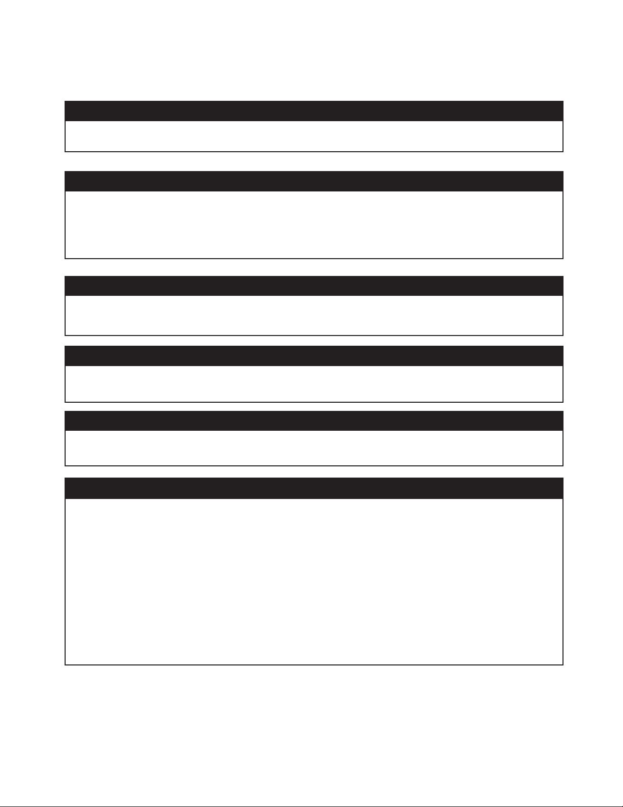
CARACTÉRISTIQUES DU COMPRESSEUR
13
11
4
3
12
5
6
2
10
9
1
7
1. Moteur, manostat
2. Pompe du compresseur d’air
3. Soupape de sûreté
4. Manomètre de pression de réservoir
5. Manomètre de refoulement
6. Régulateur de pression
7. Conduite de refoulement
8. Cordon secteur 115 volts
9. Ouvertures de ventilation / coiffe de
protection
10. Déconnexion rapide
11. Filtre d'entrée d'air
12. Robinet de purge du réservoir d'air
13. Valve de démarrage à froid
8
8
Page 25

8
CARACTÉRISTIQUES DU COMPRESSEUR
1). MOTEUR / MANOSTAT : Ce commutateur est utilisé pour démarrer ou arrêter le
compresseur d’air. En le passant sur la position Auto, le manostat est alimenté et de
façon automatique commande le démarrage du moteur quand la pression dans le
réservoir d’air est en dessous du seuil de pression basse fixé en usine. Quand il est
sur la sélection Start / Stop, le manostat commande la coupure du moteur quand la
pression dans le réservoir d’air est au dessus du seuil de pression haute fixé en
usine. Pour des raisons de sécurité le manostat comporte également une soupape de
surpression située sur le côté, conçue pour relâcher automatiquement l’air comprimé
de la tête de pompe du compresseur d’air et de sa conduite de déchargement quand
l’appareil atteint sa pression de coupure ou est arrêté. Cela permet au moteur de
redémarrer librement. Le passage du manostat en position Off lui coupe son
alimentation et arrête le compresseur d’air.
2). RUPTEUR THERMIQUE DU MOTEUR : Le moteur possède une protection contre le
suréchauffement. Si le moteur chauffe trop pour une quelconque raison, le rupteur
thermique va couper son alimentation, ce qui empêchera qu’il soit endommagé.
Attendez jusqu’à ce que le moteur soit refroidi. Le moteur a également un coupecircuit magnétique. Restaurez le rupteur en cas de déclenchement.
3). FILTRE D’ENTRÉE D’AIR : Ce filtre est prévu pour nettoyer l’air qui arrive à la
pompe. Pour assurer une arrivée d'air frais à la pompe continuellement propre et sec,
ce filtre doit rester toujours propre et l’ouverture de ventilation libre de toute
obstruction. Le filtre peut être déposé pour un nettoyage utilisant de l’eau
savonneuse chaude. Rincez ensuite le filtre et faites-le sécher.
4). POMPE DU COMPRESSEUR D’AIR : Pour compresser l’air, le piston monte et
descend dans le cylindre. Dans le mouvement de descente, l’air est aspiré par la
soupape d’admission, tandis que la soupape d’échappement reste fermée. Dans le
mouvement de remontée, l’air est compressé, la soupape d’admission se ferme et
l’air comprimé est chassé par la soupape d’échappement dans la conduite
d’échappement, au travers du clapet anti-retour puis dans le réservoir d’air.
5). SOUPAPE DE SÛRETÉ : Cette soupape est conçue pour éviter des pannes de
système en relâchant sa pression quand l’air comprimé atteint un niveau
prédéterminé. La soupape est réglée à l’avance par le constructeur et ne doit être
retouchée en aucune manière. Pour vérifier le bon fonctionnement de cette soupape,
tirer sur l’anneau. De l’air sous pression doit s’échapper. Quand l’anneau est relâché
la soupape se remet en place.
6). ROBINET DE PURGE DU RÉSERVOIR D’AIR : Ce robinet de purge est utilisé pour
évacuer l’humidité du réservoir d’air après l’arrêt du compresseur. Ne JAMAIS
essayer d’ouvrir ce robinet quand il y a plus de 10 psi (0,68 bar) de pression
dans le réservoir d’air ! Pour ouvrir ce robinet de purge, tournez son bouton
dans le sens du dévissage. Penchez le réservoir pour vous assurer que toute
l’eau coule bien par le robinet.
1
2
3
5
6
7
7). MANOMÈTRE DE RÉSERVOIR D’AIR : Ce manomètre indique la pression de
l’air comprimé en réserve dans le réservoir d’air.
). MANOMÈTRE DE REFOULEMENT : Ce manomètre indique la pression d’air
disponible du côté de sortie du régulateur. Cette pression est contrôlée par le
régulateur et elle est toujours inférieure ou égale à celle de l’air du réservoir.
9). RÉGULATEUR DE PRESSION : L’air sous pression venant du réservoir d’air
est contrôlé par le bouton du régulateur. En tournant ce bouton dans le sens du
vissage on augmente la pression de sortie, et en sens contraire on la diminue.
10). CONDUITE DE REFOULEMENT : Veuillez garder en mémoire que cette conduite
est très chaude.
9
8
9
10
Page 26

PRÉPARATION
MISE EN ŒUVRE INITIALE :
1. Lisez les mises en garde de sécurité avant de mettre en œuvre le compresseur d’air.
EMPLACEMENT:
ATTENTION
De façon à éviter d’endommager le compresseur d’air, ne l’inclinez pas
transversalement ou longitudinalement de plus de 10°.
1. Placez le compresseur d’air au moins à 30 cm de tous les obstacles qui pourraient empêcher une bonne
ventilation. Ne le placez pas dans toute zone où :
- il y a une évidence de fuites de gaz ou d’huile.
- il y a des vapeurs ou des matériaux inflammables.
AVERTISSEMENT
Des blessures graves voire mortelles peuvent survenir si des étincelles électriques
du moteur ou du manostat entrent en contact avec de vapeurs inflammables, de la
poussière de combustible, des gaz ou d’autres matériaux combustibles. Quand vous
utilisez le compresseur d’air pour vaporiser de la peinture, placez-le le plus loin possible
de la zone de travail, utilisez une rallonge de flexible plutôt qu’une rallonge de cordon
secteur.
- où la température de l’air tombe en dessous de 0°C ou dépasse 40°C.
- où de l’air très pollué ou de l’eau peut entrer dans le compresseur
ALIMENTATION ÉLECTRIQUE :
DANGER
Une connexion incorrecte du conducteur de mise à la terre de l’équipement peut
entraîner un risque de commotion électrique ou d’électrocution. Faites vérifier par un
électricien qualifié ou un agent de dépannage si vous avez un doute quant à la bonne
mise à la terre de la prise secteur. N’utilisez aucun type d’adaptateur avec ce produit.
Si la réparation ou le remplacement du cordon secteur s’avère nécessaire, ne connectez
pas le fil de terre sur l’une ou l’autre des bornes à lame plate. Le fil avec isolant dont la
surface extérieure est verte avec ou sans rayures jaunes est le fil de terre.
AVERTISSEMENT
Ce produit doit être mis à la terre. En cas d’hypothétique dysfonctionnement ou panne, la
mise à la terre fournit un chemin de moindre résistance pour le courant électrique, ce qui
réduit le risque de commotion électrique ou d’électrocution. Ce produit est équipé d’un
cordon ayant un fil pour la mise à la terre de l’équipement et une fiche secteur de type mise
à la terre. Cette fiche doit être enfoncée dans une prise murale adéquate correctement
installée et reliée à la terre en conformité avec toutes les normes et réglementations
locales.
SENCO ne recommande pas l’utilisation de rallonges secteur, car cela provoque de la perte de puissance et une surchauffe
du moteur. Utilisez plutôt une rallonge de flexible de sortie d’air comprimé. Si vous étiez dans l’obligation d’utiliser une
rallonge secteur, elle doit être branchée sur boîte de raccordement protégée par disjoncteur différentiel ou sur des prises
protégées. Quand vous utilisez une rallonge secteur, observez ces règles
Longueur de câble Calibre AWG de fil
Jusqu’à 7,5 m
Jusqu’à 30 m 10
Jusqu’à 45 m 8
Jusqu’à 75 m 6
N’utilisez que des rallonges à trois broches munies de fiches secteur à trois broches pour mise à la terre, et des douilles
secteur trois broches qui pourront recevoir le fiche secteur du produit. N’utilisez que des rallonge secteur ayant au moins de
spécifications égales à celles du cordon du produit. N’utilisez pas de rallonge électrique usagée. Examinez la rallonge avant
de l’utiliser et rejetez-la si elle est endommagée. N’abusez pas des rallonges électriques et ne tirez pas sur le câble pour
débrancher. Gardez le cordon à l’écart de la chaleur et des angles vifs. Coupez toujours le compresseur d’air à son
interrupteur avant de débrancher sa prise secteur.
12
:
10
Page 27

FONCTIONNEMENT
LISTE DE VÉRIFICATIONS PRÉLIMINAIRES :
1. Enlevez toute humidité du réservoir d’air comprimé. Faites retomber la pression en activant un outil mu
par air comprimé, puis ouvrez le robinet de purge en bas du réservoir. Refermez-le bien quand l’eau est évacuée.
AVERTISSEMENT :
robinet de purge quand il y a une pression d’air de plus de 10 psi (0,68 bar) dans le
réservoir.
Risque de blessure corporelle. N’essayez JAMAIS d’ouvrir le
2. Assurez-vous que le commutateur du moteur du compresseur est en position d’arrêt (OFF).
3. Assurez-vous que toutes les soupapes de sécurité fonctionnent bien.
4. Vérifiez que toutes les protections et couvercles sont en place et bien fixés.
DÉMARRAGE :
1. Assurez-vous que le levier de la boîte de commutateur de pression est sur position d’arrêt (OFF).
2. Branchez la fiche secteur dans la prise secteur murale.
3. Déplacez le levier de la boîte de commutateur de pression en position AUTO.
4. OPTION démarrage/coupure (START/STOP) : Passez sur la position de marche (ON). Cela va permettre
au compresseur d’air de commencer à bâtir une pression dans le réservoir d’air et de s’arrêter quand la
pression prédéterminée correcte est atteinte. Quand la pression descend par l’utilisation de l’air
comprimé, le compresseur se met tout seul en marche pour la remonter.
5. Réglez la pression d’air de sortie en tournant le bouton du régulateur (sens du dévissage pour la
baisser, sens du vissage pour l’augmenter).
6. Si vous remarquez bruit ou vibration anormaux, arrêtez le compresseur d’air et reportez-vous à la
section Dépannage.
COUPURE :
1. Pour arrêter le compresseur d’air, déplacez le levier de la boîte de commutateur de pression en position
d’arrêt (OFF). N’arrêtez JAMAIS le compresseur d’air en débranchant sa fiche secteur. Cela peut provoquer
un risque d’électrocution.
2. Faites retomber la pression en activant un outil mu par air comprimé, ou en tirant sur l’anneau de la
soupape de sûreté.
3. Une fois que la pression dans le réservoir d’air est retombée à moins de 10 psi, ouvrez le robinet de
purge sous le réservoir pour évacuer toute l’eau résiduelle.
4. Laissez le compresseur refroidir.
5. Essuyez proprement le compresseur et entreposez-le dans un endroit sûr et hors gel.
ENTRETIEN
Lisez ce manuel d’instructions avant d’effectuer un quelconque entretien. Les procédures qui suivent
doivent être suivies au moment de l’arrêt du compresseur d’air en cas d’entretien ou de dépannage.
1. Coupez le compresseur d’air à son interrupteur.
AVERTISSEMENT : Ne présumez jamais que vous pouvez intervenir en sécurité sur le
compresseur d’air juste parce qu’il ne tourne pas. Il pourrait redémarrer inopinément
2. Débranchez le cordon secteur de la prise secteur.
3. Ouvrez toutes les vidanges.
4. Laissez refroidir le compresseur d’air avant de démarrer l’intervention.
TABLEAU D’ENTRETIEN
PROCÉDURE
Purger la condensation du réservoir d’air X
Chercher des bruits/vibrations anormaux X
Chercher des fuites d’air X
Inspecter le filtre à air
Nettoyer l’extérieur du compresseur
Vérifier la soupape de sûreté X
QUOTIDIEN
HEBDOMADAIRE
X
X
11
!
MENSUEL
Page 28

DÉPANNAGE
Symptôme 1 – Le moteur ne tourne pas ou ne redémarre pas
CAUSE PROBABLE
Le cordon secteur n’est pas branché.
Le commutateur moteur/pression est sur arrêt
(OFF).
REMÈDE
Connectez le cordon sur la prise secteur.
Passez le commutateur en position de marche
(ON).
Le rupteur thermique s’est déclenché.
Calibre de fil insuffisant ou longueur de rallonge
trop élevée.
La pression d’air du réservoir dépasse le seuil de
pression de redémarrage du moteur.
La soupape de relâchement de pression du
commutateur moteur/pression n’a pas déchargé
la pression de la tête de pompe.
Moteur, condensateur de moteur, commutateur
moteur/pression potentiellement défectueux.
Coupez le compresseur d’air, attendez que le
moteur refroidisse, puis vérifiez le rupteur du
moteur.
Vérifiez que le fusible a le bon ampérage.
Vérifiez si la tension secteur ne descend pas trop
bas.
Débranchez tous les autres appareillages de ce
circuit d’alimentation, ou aménagez un circuit
d’alimentation électrique que pour le compresseur.
Vérifiez en page 10 la bonne correspondance entre
calibre et longueur du cordon secteur.
Le moteur va démarrer automatiquement quand la
pression du réservoir sera tombée sous le seuil de
redémarrage du compresseur.
Purgez la conduite en passant le commutateur sur
l’arrêt (OFF).
Contactez le support à la clientèle de Senco.
Symptôme 2 – Sur l’option démarrage/coupure (Start/Stop) le moteur tourne sans arrêts
CAUSE PROBABLE
Le commutateur moteur/pression ne coupe pas
le moteur quand la pression d’air du réservoir
atteint le seuil haut et le soupape de sûreté doit
se déclencher.
Le compresseur d’air est sous-dimensionné.
Symptôme 3 – L’air continue de fuir à la valve de purge du commutateur moteur/pression après
l’arrêt du moteur.
CAUSE PROBABLE
Vanne de pilotage défectueuse, le clapet
anti-retour est resté bloqué en position ouverte.
REMÈDE
Passez le commutateur moteur/pression sur la
position d’arrêt (OFF). Si le moteur ne se coupait
pas, débranchez le compresseur d’air. Si les
contacts électriques se sont soudés, remplacez le
commutateur.
Limitez la pression de l’air à la capacité du
compresseur d’air. Utilisez soit un outil moins
puissant soit un compresseur d’air de plus forte
capacité.
REMÈDE
Démontez, nettoyez ou remplacez.
12
Page 29

DÉPANNAGE
Symptôme 4 – L’air continue de fuir à la valve de purge du commutateur moteur/pression quand le
moteur tourne.
CAUSE PROBABLE
Commutateur moteur/pression défectueux
Symptôme 5 – L’air fuit au niveau de la soupape de sûreté.
CAUSE PROBABLE
Commutateur moteur/pression défectueux.
Symptôme 6 – L’air fuit au niveau de raccords.
CAUSE PROBABLE
Les raccords ne sont pas assez serrés.
Symptôme 7 – L’air fuit au niveau du réservoir.
CAUSE PROBABLE
Réservoir défectueux ou percé par la rouille.
REMÈDE
Remplacement.
REMÈDE
Remplacement.
REMÈDE
Resserrez les raccords là où vous entendez l’air
s’échapper. Vérifiez l’étanchéité des raccords
avec de l’eau savonneuse.
REMÈDE
Il faut remplacer le réservoir d’air. N’essayez pas
de réparer un réservoir d’air !
Symptôme 8 – L’air fuit au niveau du filtre d’entrée.
CAUSE PROBABLE
Soupape flexible d’admission défectueuse.
Symptôme 9 – Pression d’air comprimé insuffisante au niveau de l’outil ou accessoire.
CAUSE PROBABLE
Le bouton de réglage du régulateur n’est pas
assez tourné côté pression plus élevée ou le
régulateur de pression est défectueux.
Le filtre d’admission d’air est obstrué.
Il y a des fuites d’air.
Le compresseur d’air n’est pas assez puissant
pour la demande.
REMÈDE
Contactez le service à la clientèle de Senco au
888-222-8144.
REMÈDE
Réglez le bouton du régulateur pour plus de
pression, ou changez le régulateur.
Nettoyez le filtre.
Recherchez et réparez les fuites.
Vérifiez la consommation en air comprimé de
l’accessoire. Si cette demande est supérieure à la
production (pieds cubes par minute) du
compresseur d’air, il vous faut un compresseur
plus gros.
13
Page 30

DÉPANNAGE
Symptôme 10 – Le compresseur d’air ne produit pas assez d’air comprimé.
CAUSE PROBABLE
Le filtre d’admission d’air est obstrué.
Soupape flexible d’admission défectueuse.
Symptôme 11 – Humidité dans l’air en sortie.
CAUSE PROBABLE
Condensation dans le réservoir d’air causée
par un niveau élevé d’hygrométrie
atmosphérique, ou le fait que le compresseur
d’air n’a pas tourné assez longtemps.
REMÈDE
Nettoyez le filtre.
Purgez le réservoir d’air et mesurez le temps de
fonctionnement de la pompe. Comparez-le aux
spécifications. S’il est inférieur, démontez la tête
de pompe et inspectez la plaque porte soupape,
nettoyez ou remplacez.
REMÈDE
Purgez bien le réservoir d’air après chaque
utilisation. Purgez-le plus souvent par temps
humide et utilisez un filtre sur la conduite d’air.
14
Page 31

SPÉCIFICATIONS
Référence de modèle PC0968
Moteur
Puissance 1.5 CV
Tension 115 V
Ampérage 8 A
Fréquence 60 Hz
Phase Monophasé
Vitesse de rotation 3450 tours/minute
Pompe de compresseur
Nombre de cylindres 1
Étage de compression 1
Carter Aluminium
Paliers Billes
Cylindre Aluminium/Steel Sleeve
Soupapes Flexible à ruban simple
Tête Aluminium
Filtre Insert
Réglage du commutateur moteur/pression
Seuil haut de coupure 120 psi (8,3 bar)
Seuil bas de démarrage 90 psi (6 bar)
Commandes Démarrage / coupure
Réservoir d’air
Capacité 2 gallon US (7,5 l)
Performance globale
Déplacement d’air en pieds3/min
Capacité sous 90 psi 2,2
Pression maximale 120 psi (8,3 bar)
Temps d’activation de pompe
de 0 à 120 psi 68 secondes
Temps de récupération de 90
à 120 psi 15 secondes
Poids
Net 17,25 kg (38 livres)
Dimensions
Longueur x largeur x hauteur 40,6 x 38,1 x 34,3 cm (16" x 15 "x 13.5"
4
15
Page 32

GARANTIE SENCO POUR LE COMPRESSEUR ET LES PIÈCES
Ce compresseur a été conçu et construit en utilisant les normes les plus élevées quant aux matériaux et à la main d’œuvre.
GARANTIE DU COMPRESSEUR :
La durée de cette garantie est de un an à compter de la date d’achat par le client du commerce de détail d’origine. Durant cette
période Senco Products, Inc. réparera ou remplacera à son choix toute(s) pièce(s) d’origine pour le premier acheteur. Cela sera gratuit
une fois que les pièces seront bien reconnues défectueuses pour les matériaux ou la main d’œuvre par le service de dépannage sous
garantie agréé Senco, avec les exceptions et exclusions décrites ci-dessous. Toute pièce de remplacement fournie portera une
garantie propre pour la durée de période de garantie encore applicable de la pièce qu’elle remplace. Quand la réparation ou le
remplacement de pièces ou du compresseur est nécessaire, l’acheteur d’origine doit renvoyer le compresseur complet ou la pièce,
avec les coûts de transport payés à l’avance, jusqu’au centre de réparation sous garantie agréé Senco le plus proche, accompagné de
la facture ou ticket de caisse ou autre preuve d’achat pour montrer que le compresseur ou la pièce est toujours sous garantie.
Senco garantit toutes les pièces (sauf celles listées ci-dessous) de votre compresseur d’air Senco comme étant exemptes de défauts
dus aux matériaux et à la main d’œuvre pendant les périodes suivantes
1. Pendant un an à partir de la date d’achat d’origine :
Pompe de compresseur
Ensemble de réservoir
Plomberie
Cordon secteur
2. Pendant 90 jours de date d'achat initial:
Manomètre Soupape de sûreté
Robinet de purge
Les pièces défectueuses non sujettes à usure et détérioration normale seront réparées ou remplacées, au choix de Senco, pendant
leur période de garantie. Dans tous les cas le remboursement est limité à au prix d’achat déboursé.
EXCLUSIONS :
Cette garantie ne couvre pas :
1. Les pièces endommagées par usure naturelle, application non conforme, utilisation abusive, accidents, fonctionnement à vitesse ou
tension (appareillages électriques) autres que les recommandations, mauvais stockage, ou dommages occasionnés durant le
transport.
2. Les pièces endommagées par non respect des instructions d’emploi, des spécifications, et des calendriers d’entretien.
3. Les charges de main d’œuvres, les pertes ou dommages, résultant d’un fonctionnement inadéquat, d’interventions ou de
réparations effectuées par des personnes autres que celles d’un centre de réparations sous garantie agréé Senco.
4. L’utilisation de pièces autres que des pièces Senco d’origine, qui annulerait la garantie.
:
Cette garantie est conditionnée par la bonne utilisation du compresseur par son acheteur, et ne couvre pas
(A) Conditions anormales, accident, négligence, mauvaise utilisation ou stockage incorrect de l’unité.
(B) Déviation par rapport aux instructions d’emploi et d’entretien.
(C) Modifications par des personnes non autorisées par Senco.
(D) Réparations ou maintenance (autre que la purge de routine du réservoir d’air demandée dans votre manuel d’utilisation et
d’entretien) effectués par des personnes autres que celles de Senco ou de ses agents agréés.
(E) Dommages dus au transport.
CETTE GARANTIE EST LA SEULE GARANTIE SUR CE COMPRESSEUR, ET TOUTES LES AUTRES GARANTIES, QU’ELLES
SOIENT ORALES, ÉCRITES, EXPLICITES OU IMPLICITES, INCLUANT, MAIS NON LIMITÉ À, LA GARANTIE IMPLICITE DE
VALEUR MARCHANDE OU D’ADÉQUATION À UNE FINALITÉ SPÉCIFIQUE, SONT EXCLUES. LES COMPENSATION POUR
L’ACHETEUR OU L’UTILISATEUR SONT SEULEMENT ET EXCLUSIVEMENT CELLES DÉFINIES PLUS HAUT. SENCO
PRODUCTS, INC. NE POURRA EN AUCUN CAS ÊTRE TENU POUR RESPONSABLE DE TOUS DOMMAGES ANNEXES,
CONSÉCUTIFS, INDIRECTS OU SPÉCIAUX. EN AUCUN CAS, QUE CE SOIT RÉSULTANT D’UNE RUPTURE DE CONTRAT, DE
GARANTIE, DE TORT (INCLUANT LA NÉGLIGENCE) OU AUTRE, LA RESPONSABILITÉ SE SENCO NE POURRA ÊTRE
ENGAGÉE AU-DELÀ DU PRIX DU COMPRESSEUR QUI A ÉTÉ À L’ORIGINE DE LA RÉCLAMATION OU DE LA RESPONSABILITÉ.
TOUTE RESPONSABILITÉ LIÉE À L’UTILISATION DE CE COMPRESSEUR CESSERA À L’EXPIRATION DE LA PÉRIODE DE
GARANTIE DÉFINIE PRÉCÉDEMMENT.
:
Remplacement du compresseur suite à une catastrophe naturelle
Senco remplacera également tout compresseur détruit par une catastrophe naturelle telle que inondation, tremblement de terre,
ouragan ou autre désastre majeur résultant entièrement des forces de la nature. Une déclaration dans ce cadre sera honorée à la
condition que l’acheteur d’origine concerné ait auparavant renvoyé sa carte de garantie dûment remplie, et puisse fournir la preuve de
sa possession, ainsi qu’une déclaration acceptable décrivant cette catastrophe naturelle provenant d’un expert d’assurance, de la
police, ou d’une autre source officielle. Pour obtenir des instructions sur la façon d’établir une telle demande, appelez au 1-800-543-
4596.
SENCO PRODUCTS, INC.
CINCINNATI, OHIO, 45244-1611 USA
Page 33

Consultas? Comentarios? Ilame sin cargo a la línea de asistencia de SENCO: 1-800-543-4596 ó envíe a toolprof@senco.com
Compresor de aire eléctrico PC0968
Senco Products, Inc.
8485 Broadwell Rd.
Cincinnati, OH 45244
Instruccione de Operación
© 2003 by Senco Products, Inc.
PC0968 Revised July 31, 2003
(Replaces 6/30/03)
En este manual se incluyen avisos para el uso seguro de este compresor.
Page 34

INDICE
G
INTRODUCCIÓN ............................................................................................... 3
AVISO DE SEGURIDAD..................................................................................... 3
INSPECCIÓN ....................................................................................................
ADVERTENCIAS ............................................................................................... 4
SISTEMA ELÉCTRICO....................................................................................... 4
EXPLOSIÓN O INCENDIO................................................................................
ESTALLIDO ....................................................................................................... 5
RESPIRACIÓN ..................................................................................................
QUEMADURAS .................................................................................................
OBJETOS VOLANTES....................................................................................... 6
PIEZAS MÓVILES..............................................................................................
NEGLIGENCIA .................................................................................................. 7
DAÑO AL COMPRESOR DE AIRE.................................................................... 7
CARACTERÍSTICAS DEL COMPRESOR ........................................................ 8
PREPARACIÓN................................................................................................. 10
MONTAJE INICIAL ............................................................................................ 10
EMPLAZAMIENTO............................................................................................. 10
SISTEMA ELÉCTRICO...................................................................................... 10
FUNCIONAMIENTO .......................................................................................... 11
LISTA DE COMPROBACIÓN ANTES DE LA PUESTA EN MARCHA............... 11
PUESTA EN MARCHA ...................................................................................... 11
PARADA ............................................................................................................ 11
MANTENIMIENTO............................................................................................. 11
LOCALIZACIÓN Y SOLUCIÓN DE AVERÍAS ................................................. 12-14
ESPECIFICACIONES ....................................................................................... 15
ARANTÍA .........................................................................................................16
3
5
6
6
7
2
Page 35

INTRODUCCIÓN
¡Lo felicitamos por la compra de su nuevo compresor de aire SENCO®! Puede tener la seguridad
de que su compresor de aire SENCO fue construidos con el más alto nivel de precisión y
exactitud. Cada componente fue sometido a pruebas rigurosas por los técnicos para garantizar
la calidad, duración y rendimiento de este compresor de aire.
Este manual del operador fue redactado para su beneficio. Al leer y respetar los sencillos pasos
de seguridad, instalación, operación y mantenimiento descritos en este manual, disfrutará de
muchos años de funcionamiento sin problemas de su nuevo compresor de aire SENCO. El
contenido de este manual está basado en la información más reciente del producto disponible al
momento de la publicación. El fabricante se reserva el derecho de hacer cambios en el precio, el
color, los materiales, el equipo, las especificaciones o los modelos en cualquier momento sin
previo aviso.
¡AVISO DE SEGURIDAD!
Un aviso de seguridad titulado "PELIGRO, ADVERTENCIA o ATENCIÓN" estará encuadrado en un
"AVISO DE SEGURIDAD". Este encuadre se utiliza para designar y recalcar los avisos de seguridad que
deben respetarse cuando se maneja este compresor de aire. Los avisos de seguridad van acompañados
de "palabras de aviso" que designan el grado o nivel de la gravedad del riesgo. Las "palabras de aviso"
que se utilizan en este manual son las siguientes:
PELIGRO:
ERTENCIA :Indica una situación potencialmente peligrosa que, si no se evita,
AV
PODRÍA resultar en lesiones graves o muerte.
ATENCION :
PUEDE resultar en lesiones leves o moderadas o daño al compresor de aire.
PROPORCIONE SIEMPRE UN EJEMPLAR DE ESTE MANUAL A TODA PERSONA QUE UTILICE ESTE EQUIPO.
ANTES DE MANEJAR ESTE COMPRESOR DE AIRE, LEA TODAS LAS INSTRUCCIONES EN ESTE MANUAL Y
AQUELLAS SUMINISTRADAS POR LOS FABRICANTES DE LOS EQUIPOS SUPLEMENTARIOS, Y DESTAQUE
ESPECIALMENTE LAS "MEDIDAS DE SEGURIDAD" PARA PREVENIR LA POSIBILIDAD DE LESIONES AL
OPERADOR.
Indica una situación inminentemente peligrosa que, si no se evita,
RESULTARÁ en lesiones graves o muerte.
Indica una situación potencialmente peligrosa que, si no se evita,
Estos símbolos se usan para llamar la atención hacia artículos o procedimientos
que podrían ser peligrosos para usted u otras personas que estén utilizando este
equipo.
INSPECCIÓN
Desembale el compresor de aire y anote el número de serie en el espacio más abajo provisto para ese fin. Inspeccione
para ver si hay indicios de daños obvios u ocultos ocurridos durante el transporte. Antes de hacer funcionar el
compresor de aire, asegúrese de reemplazar todas las piezas dañadas y reparar las averías mecánicas.
NÚMERO DE SERIE__________________________________________
Para consultas o comentarios, llame sin cargo a la línea de asistencia de SENCO: 1-800-543-4596 ó envíe e-mail a:
toolprof@Senco.com
Por favor tenga la información siguiente a mano para todas las llamadas de servicio:
1. Número de modelo
2. Número de serie
3. Fecha y lugar de compra
Senco, 8485 Broadwell Road, Cincinnati, OH 45244
3
Page 36

MEDIDAS DE SEGURIDAD
LEA TODAS LAS MEDIDAS DE SEGURIDAD ANTES DE USAR EL COMPRESOR DE AIRE
RIESGO
RIESGO DE
ELECTROCHOQUE
O ELECTROCUCIÓN
CONSECUENCIA POTENCIAL
Si no se conecta a tierra
correctamente el compresor de
aire, podrían ocurrir lesiones
graves o la muerte. Su compresor
de aire es alimentado por
electricidad y puede causar
electrochoque o electrocución si
no se usa debidamente.
El cordón eléctrico puede causar
electrochoque.
Puede ocurrir electrochoque si no
se maneja correctamente el
compresor de aire.
PREVENCIÓN
Asegúrese de que el compresor de aire
está enchufado a un tomacorriente
correctamente conectado a tierra y que
suministra el voltaje correcto y la
protección adecuada mediante fusibles.
Revise el cordón de alimentación para
ver si hay indicios de aplastamiento,
cortes o daños por calor. Reemplace el
cordón defectuoso antes de usar el
compresor.
Mantenga todas las conexiones secas y
elevadas del suelo. No deje que los
cordones eléctricos queden en el agua o
en una posición donde pudieran quedar
en contacto con agua. No toque el
enchufe con las manos mojadas.
No tire del cordón eléctrico para
desenchufarlo del tomacorriente.
No maneje nunca el compresor de aire
en condiciones mojadas o a la
intemperie cuando está lloviendo.
No maneje nunca el compresor de aire
con los protectores o cubiertas fuera de
lugar o dañados.
Toda conexión de cableado o reparación
eléctrica en este compresor de aire debe
ser ejecutada por personal de servicio
autorizado y de acuerdo con los códigos
eléctricos nacionales y locales.
Pueden ocurrir lesiones graves o
la muerte si personas sin
experiencia intentan hacer las
reparaciones eléctricas.
4
Antes de abrir un caja de conexiones
eléctricas, apague siempre el compresor
de aire, descargue la presión y
desenchufe el compresor de la fuente de
alimentación. Deje que el compresor de
aire se enfríe. Nunca dé por supuesto
que puede trabajar sin peligro en el
compresor de aire, simplemente por que
no está funcionando. ¡Podría arrancar en
cualquier momento!
Page 37

MEDIDAS DE SEGURIDAD
LEA TODAS LAS MEDIDAS DE SEGURIDAD ANTES DE USAR EL COMPRESOR DE AIRE
RIESGO
RIESGO DE EXPLOSIÓN
O INCENDIO
CONSECUENCIA POTENCIAL
Las chispas eléctricas que
ocurren normalmente en el motor
y el interruptor de presión puede
causar lesiones graves o la
muerte.
Pueden ocurrir graves lesiones si
cualquiera de los orificios de
venteo del compresor se obtura,
causando el sobrecalentamiento e
incendio del compresor de aire.
PREVENCIÓN
Utilice siempre el compresor de
aire en un lugar bien ventilado
libre de vapores inflamables,
polvo combustible, gases u otros
materiales combustibles.
Si está pulverizando con un
material inflamable, sitúe el
compresor de aire a por lo menos
20 pies de distancia de la zona de
pulverización.
(Es posible que se necesite una
manguera adicional.)
Nunca coloque objetos afirmados
contra el compresor de aire o
encima del mismo. Utilice el
compresor de aire a por lo menos
12 pulgadas de distancia de la
pared u obstrucción que pudiera
restringir la ventilación adecuada.
RIESGO DE
ESTALLIDO
Pueden ocurrir lesiones graves o
la muerte si el tanque de aire
llegara a explotar por falta de
mantenimiento adecuado.
Pueden ocurrir lesiones graves a
causa de una avería del
compresor de aire o explosión de
los accesorios por el uso de
componentes, implementos o
accesorios incorrectos.
Vacíe el tanque de aire
diariamente o después de cada
uso para evitar la acumulación de
humedad en el tanque.
Si el tanque comienza a perder
aire, cámbielo inmediatamente.
Nunca repare, suelde o haga
modificaciones al tanque de aire o
sus accesorios. Nunca cambie los
ajustes de presión de fábrica.
Nunca sobrepase las capacidades
máximas de presión admisibles
de los accesorios.
Debido al calor extremo, no use
tubería de plástico ni juntas
estañosoldadas en el tubo de
descarga.
Nunca use el compresor de aire
para inflar objetos pequeños de
baja presión tales como juguetes.
5
Page 38

MEDIDAS DE SEGURIDAD
LEA TODAS LAS MEDIDAS DE SEGURIDAD ANTES DE USAR EL COMPRESOR DE AIRE
RIESGO
RIESGO PARA LAS
VIAS RESPIRATORIAS
RIESGO DE
QUEMADURAS
POTENTIAL CONSEQUENCE
Podrían ocurrir lesiones graves o
la muerte si se inhala el aire
comprimido. El chorro de aire
puede contener monóxido de
carbono, vapores tóxicos o
partículas sólidas.
Los materiales aplicados con
pulverizador tales como pintura,
diluyentes de pintura,
quitapinturas, insecticidas,
matamalezas, etc. contienen
vapores nocivos y venenos.
Podrían ocurrir lesiones graves si
se tocan las piezas metálicas al
descubierto.
Estas partes pueden permanecer
calientes por algún tiempo
después de apagar el compresor
de aire.
PREVENCIÓN
Nunca inhale el aire del compresor de
aire ya sea directamente o a través de
un aparato respirador conectado al
compresor de aire.
Utilice el compresor de aire solamente
en un lugar bien ventilado. Siga todas
las instrucciones de seguridad
suministradas con los materiales que
está pulverizando. Es posible que
tenga que usar un respirador cuando
trabaje con ciertos materiales.
No permita que ninguna parte de su
cuerpo u otros materiales queden en
contacto con las piezas metálicas al
descubierto en el compresor de aire.
RIESGO DE SER
GOLPEADO POR
OBJETOS VOLANTES
El chorro de aire comprimido
puede dañar los tejidos blandos.
Pueden ocurrir lesiones graves a
causa de residuos sueltos
lanzados a gran velocidad por el
chorro de aire comprimido.
Use siempre gafas de seguridad "Z87"
exigidas por OSHA para protegerse los
ojos contra los residuos volantes.
Nunca dirija el chorro de aire contra su
cuerpo u otras personas o animales.
Nunca deje el compresor de aire
presurizado desatendido. Apague el
compresor de aire y descargue la
presión antes de intentar hacer
trabajos de mantenimiento, conectar
herramientas o accesorios.
Manténgase siempre a una distancia
segura de personas y animales
mientras utiliza el compresor de aire.
No traslade el compresor de aire
mientras el tanque está presurizado.
No intente mover el compresor de aire
tirándolo de la manguera.
6
Page 39

MEDIDAS DE SEGURIDAD
LEA TODAS LAS MEDIDAS DE SEGURIDAD ANTES DE USAR EL COMPRESOR DE AIRE
RIESGO
RIESGO DE LAS PIEZAS
EN MOVIMIENTO
RIESGO POR
NEGLIGENCIA
CONSECUENCIA POTENCIAL
Riesgo de ser lesionado por las
piezas en movimiento. Este
compresor de aire funciona
automáticamente cuando el
interruptor de presión está en la
posición de "ON/AUTO"
(encendido/automático).
Riesgo de lesionarse debido al
uso descuidado.
PREVENCIÓN
Apague siempre el compresor de aire
cuando no esté en uso. Antes de
hacer trabajos de mantenimiento,
purgue la presión de la manguera de
aire y desenchufe el cordón eléctrico
del tomacorriente. Todas las
reparaciones del compresor de aire
debe hacerlas una técnico de
servicio autorizado. Nunca dé por
supuesto que no es peligroso
trabajar en el compresor de aire,
simplemente porque no está
funcionando. ¡Puede arrancar
imprevistamente en cualquier
momento!
No lo utilice sin que tenga instaladas
las cubiertas o protectores.
Reemplace las cubiertas y los
protectores antes de usar el
compresor de aire.
¡Nunca permita que niños o
adolescentes usen este compresor
de aire!
RIESGO DE DAÑAR EL
COMPRESOR DE AIRE
Riesgo de reparaciones
importantes.
Manténgase alerta - preste atención a
lo que está haciendo.
No use el compresor de aire cuando
está fatigado o ha tomado bebidas
alcohólicas o drogas.
Sepa cómo parar el compresor de
aire. Aprenda bien el manejo de los
controles.
No use el compresor de aire sin el
filtro de aire.
No use el compresor de aire en un
ambiente corrosivo.
Coloque siempre el compresor de
aire en posición estable y segura
para evitar que se caiga mientras
está funcionando.
Siga todas las instrucciones de
mantenimiento presentadas en este
manual.
Llene con aceite hasta la marca de
nivel en la varilla de medición
(tanque inferior)
! ¡GUARDE ESTAS INSTRUCCIONES!
7
Page 40

4
3
12
13
11
5
6
2
10
9
1
7
8
1 Interruptor de motor/presión
2 Bomba del compresor de aire
3 Válvula de seguridad
4 Manómetro del tanque
5 Manómetro de presión de salida
6 Regulador de presión
7 Tubo de descarga
8 Cordón de alimentación de 115 voltios
9 Orificios de venteo/cubierta protectora
10 Desacople rápido
11 Filtro de admisión de aire
12 Válvula de purga del tanque de aire
13 Válvula del arranque en frio
Page 41

CARACTERÍSTICAS DEL COMPRESOR
8
1) INTERRUPTOR DEL MOTOR/PRESIÓN: Este interruptor se usa para arrancar o parar
(apagar) el compresor de aire. Al moverlo a la posición "AUTO" (encendido) se
suministra alimentación automática al interruptor de presión lo que permitirá que el
motor arranque cuando la presión del tanque de aire está por debajo de la presión de
"activación" ajustada en fábrica. Cuando se coloca en la opción de Start/Stop Option
(arranque/parada), el interruptor de presión apaga el motor cuando la presión del
tanque de aire llega a la presión de "desactivación" ajustada en fábrica. Para fines de
seguridad, este interruptor también tiene una válvula de seguridad de presión ubicada
en el costado del interruptor, diseñada para descargar automáticamente el aire
comprimido del cabezal de la bomba del compresor y su tubo de descarga cuando el
compresor llega a la presión de "desactivación" o se apaga el motor. Esto permite que
el motor vuelva a arrancar libremente. Al mover el interruptor a la posición "OFF"
(apagado) se corta la alimentación al interruptor de presión y se apaga el compresor
de aire.
2) PROTECTOR CONTRA SOBRECARGA TÉRMICA DEL MOTOR: El motor eléctrico
tiene un protector contra sobrecarga térmica. Si por cualquier razón el motor se
sobrecalienta, este protector corta la alimentación eléctrica, impidiendo así que el
motor se dañe. Espere hasta que el motor esté frío. El motor también tiene un
disyuntor magnético. Reposicione el interruptor si se dispara.
3) FILTRO DE ADMISIÓN DE AIRE: El filtro está diseñado para limpiar el aire que entra
a la bomba. Para asegurar que la bomba recibe continuamente un suministro de aire
seco, frío y limpio, este filtro debe estar siempre limpio y los orificios de venteo libres
de obstrucciones. El filtro puede sacarse para limpiarlo con agua tibia jabonosa.
Enjuague el filtro y déjelo secar al aire.
1
2
3
4) BOMBA DEL COMPRESOR DE AIRE: Para comprimir el aire, el pistón sube y baja
en el cilindro. En la carrera descendente, la válvula de admisión aspira aire del exterior
mientras la válvula de escape permanece cerrada. En la carrera ascendente, el aire se
comprime, la válvula de admisión de cierra y el aire comprimido es forzado al exterior
a través de la válvula de escape al tubo de descarga, a través de la válvula de
retención (antirretorno) y al interior del tanque de aire.
5) VÁLVULA DE SEGURIDAD: Esta válvula está diseñada para evitar fallas en el
sistema, descargando la presión del sistema cuando el aire comprimido llega a un
nivel predeterminado. La válvula es preajustada por el fabricante y no debe
modificarse de manera alguna.
Para verificar si la válvula está funcionando correctamente, tire del anillo. Deberá
escapar presión de aire. Al soltar el anillo, se reasentará.
6) VÁLVULA DE PURGA DEL TANQUE DE AIRE: Esta válvula se usa para purgar la
humedad del tanque (tanques) de aire después que se apaga el compresor de aire.
¡NUNCA intente abrir la válvula de purga cuando la presión en el tanque es superior
a 10 psi! Para abrir la válvula de purga, gire la perilla en sentido contrario a las
agujas del reloj. Incline el tanque para asegurarse que toda la condensación se
vacía a través de la válvula.
7) MANÓMETRO DEL TANQUE DE AIRE: Este manómetro indica la presión de
aire de reserva en el tanque (tanques) de aire.
) MANÓMETRO DE PRESIÓN DE SALIDA: Este manómetro indica la presión
de aire disponible en el lado de salida del regulador. Esta presión la controla el
regulador y siempre es menor o igual que la presión del tanque de aire.
9) REGULADOR DE PRESIÓN: La presión de aire proveniente del tanque de aire
se controla mediante la perilla del regulador. Gire la perilla de regulación en
sentido de las agujas del reloj para aumentar la presión de descarga, y en sentido
contrario para disminuirla.
5
6
7
8
9
10
10) TUBO DE DESCARGA: Sírvase notar que el tubo de descarga está muy caliente.
9
Page 42

PREPARACIÓN
MONTAJE INICIAL:
1. Lea las medidas de seguridad antes de montar el compresor de aire.
EMPLAZAMIENTO:
Para evitar dañar el compresor de aire, no lo incline más de 10" en sentido transversal
ATENCIÓN
o longitudinal.
1. Coloque el compresor de aire a una distancia de por lo menos 12 pulgadas de obstáculos que pudieran impedir
la ventilación adecuada.
No coloque el compresor de aire en un lugar:
-donde hay evidencia de fugas de aceite o gas.
-donde puedan haber materiales o vapores de gas inflamables.
ADVERTENCIA
Podrían ocurrir graves lesiones o la muerte si las chispas eléctricas del interruptor del
motor y presión llegaran a quedar en contacto con vapores inflamables, polvo
combustible, gases u otros materiales combustibles. Cuando use el compresor de aire
para pintar con pistola, colóquelo tan lejos como sea posible del lugar de trabajo,
utilizando mangueras de aire adicionales en lugar de cordones eléctricos de extensión.
-donde las temperaturas ambientales son inferiores a 32∞F o superiores a 104∞F.
-donde existe la posibilidad de aspirar aire o agua extremadamente sucio al compresor.
SISTEMA ELÉCTRICO:
La conexión incorrecta del equipo-conductor de conexión a tierra puede resultar en
riesgo de electrochoque o electrocución. Ante cualquier duda respecto a la conexión
a tierra del tomacorriente, consulte con un perito electricista o técnico de servicio. No use ningún
tipo de adaptador con este producto. En caso de ser necesario reparar o reemplazar el cordón o
enchufe, no conecte el alambre de tierra a ninguno de los terminales de bayoneta planos. El
alambre con aislamiento de superficie exterior de color verde con o sin rayas amarillas, es el al
ambre de tierra.
PELIGRO
ADVERTENCIA
Este producto debe estar conectado a tierra. En el caso de ocurrir un malfuncionamiento
o falla, la conexión a tierra proporciona un paso de menor resistencia para la corriente
eléctrica con el fin de reducir el riesgo de electrochoque. Este producto está equipado con un
cordón que tiene un conductor de conexión a tierra del equipo y un enchufe tipo conexión a
tierra. El enchufe con conexión a tierra debe enchufarse a un tomacorriente correctamente
instalado y conectado a tierra de acuerdo con todos los códigos y ordenanzas respectivos.
1. SENCO® NO RECOMIENDA EL USO DE CORDONES DE EXTENSIÓN, ya que esto puede crear pérdida de potencia y
sobrecalentamiento del motor. Se recomienda el uso de una manguera de aire adicional en vez de un cordón de extensión.
Si el uso de un cordón de extensión es inevitable, se deberá enchufar en un interruptor accionado por corriente de pérdida
a tierra (GFCI) encontrado en las cajas de circuitos o receptáculos protegidos. Cuando use un cordón de extensión,
respete lo siguiente:
Longitud del cable Calibre del alambre
Hasta 25 pies 12 AWG
Hasta 100 pies 10 AWG
Hasta 150 pies 8 AWG
Hasta 250 pies 6 AWG
Use solamente cables de extensión de 3 clavijas que tengan enchufes de 3 clavijas tipo conexión a tierra y conectores de 3
ranuras para cordón que acepten el enchufe del producto. Use solamente cordones de extensión de una capacidad
eléctrica no inferior a la capacidad nominal del producto. No use cordones de extensión dañados. Examine el cordón de
extensión antes de usarlo, y cámbielo si está dañado. No maltrate el cordón de extensión y no tire de él para desenchufarlo.
Mantenga el cordón lejos del calor y los cantos agudos. Apague siempre el interruptor del compresor de aire antes de
desenchufar el enchufe del tomacorriente.
10
Page 43

FUNCIONAMIENTO
LISTA DE COMPROBACIÓN ANTES DE LA PUESTA EN MARCHA:
Quite toda la humedad del tanque de aire del compresor. Descargue el exceso de presión con una herramienta
1.
neumática y después abra la válvula de purga ubicada en la parte inferior del tanque. Ciérrela bien apretada
después de purgar.
ADVERTENCIA: Riesgo de lesiones corporales. ¡NUNCA intente abrir la válvula
de vaciado cuando la presión en el tanque es superior a 10 psi!
2. Asegúrese que el interruptor del motor del compresor de aire esté en la posición "OFF" (apagado).
3. Asegúrese que todas las válvulas de seguridad estén funcionando correctamente.
4. Asegúrese que todos los protectores y cubiertas estén en su lugar y firmemente instalados.
PUESTA EN MARCHA
1. Asegúrese que la palanca en la caja del interruptor de presión esté en la posición "OFF" (apagado).
2. Enchufe el cordón de alimentación en un tomacorriente conectado a tierra.
3. Mueva la palanca en la caja del interruptor de presión a la posición "AUTO" (automático).
4. OPCIÓN DE ARRANQUE/PARADA: Gírelo a la posición ON (encendido). Esto permitirá que el compresor de aire
ARRANQUE para aumentar la presión en los tanques de aire y que PARE cuando llega a la presión correcta. Cuando la presión
disminuye con el uso, el compresor de aire ARRANCA para aumentar la presión nuevamente.
5. Ajuste la presión moviendo la perilla del regulador de presión en sentido contrario a las agujas del reloj para reducir la presión
y en sentido de las agujas del reloj para aumentarla.
6. Si nota cualquier ruido o vibración fuera de lo normal, apague el compresor de aire y consulte la sección "Localización y
solución de averías."
PARADA:
1. Para apagar el compresor de aire, mueva la palanca en la caja del interruptor de presión a la posición "OFF" (apagado). No
apague NUNCA el compresor de aire desenchufándolo de la fuente de alimentación. Al hacerlo corre el riesgo de
electrocutarse.
2. Purgue el aire del tanque, utilizando una llave neumática conectada al compresor o tirando del anillo de la válvula de
seguridad.
3. Una vez que la presión en los tanques de aire indica menos de 10 libras, abra la válvula de vaciado, ubicada debajo de cada
tanque, para vaciar la humedad.
4. Deje que el compresor de aire se enfríe.
5. Limpie el compresor con un trapo y guárdelo en un lugar seguro y no expuesto a congelación.
MANTENIMIENTO
Lea el manual de instrucciones antes de efectuar trabajos de mantenimiento. Ejecute los procedimientos siguientes cuando
pare el compresor de aire para mantenimiento o servicio.
1. Apague el compresor de aire.
ADVERTENCIA: Nunca suponga que no es peligroso trabajar en el compresor de aire
simplemente porque no está funcionando. ¡Puede arrancar imprevistamente en
cualquier momento!
2. Desconecte el cordón de la fuente de alimentación principal.
3. Abra todas las válvulas de purga.
4. Espere que el compresor de aire se enfríe antes de comenzar el mantenimiento.
CUADRO DE MANTENIMIENTO
PROCEDIMIENTO
Vaciar la condensación del tanque (tanques) de aire X
Revisar si hay ruidos o vibración fuera de lo común X
Revisar si hay fugas de aire X
Inspeccionar el filtro de aire
Limpiar el exterior del compresor
Revisar la válvula de seguridad X
DIARIO
SEMANAL
MENSUAL
X
X
Page 44

LOCALIZACIÓN Y SOLUCIÓN DE AVERÍAS
Síntoma 1. El motor no funciona ni vuelve a arrancar
CAUSA PROBABLE
El cordón de alimentación no está enchufado.
El interruptor del motor/presión está en posición
"OFF" (apagado).
El interruptor de sobrecarga térmica del motor se
disparó.
Fusible quemado o disyuntor de circuito
disparado.
Alambre de calibre incorrecto o cordón de
extensión de longitud incorrecta.
La presión del tanque de aire sobrepasa la
presión de "activación" del interruptor del
motor/presión.
La válvula de seguridad en el interruptor del
motor/presión no ha descargado la presión en la
bomba.
Defecto en el motor, condensador del motor,
interruptor del motor/presión, o válvula de
retención.
SOLUCIÓN
Enchufar el cordón en un tomacorriente conectado
a tierra.
Mover el interruptor a la posición "ON"
(encendido).
Apagar el compresor, esperar hasta que el motor
esté frío y después revisar el disyuntor de circuito
del motor.
Cambiar el fusible o reactivar el disyuntor de
circuito.
Comprobar el amperaje del fusible.
Verificar si hay condiciones de bajo voltaje.
Desconectar cualquier otro artefacto eléctrico del
circuito o hacer funcionar el compresor de aire en
su propio circuito derivado.
Averigüe el calibre correcto del alambre y el largo
de cable adecuado en el cuadro en la página 10..
El motor arrancará automáticamente cuando la
presión del tanque de aire disminuye a menos de la
presión de "activación" del interruptor del
motor/presión.
Purgar la conducción, moviendo el interruptor a la
posición "OFF" (apagado).
Contactar al departamento de Atención al Cliente
de Senco.
Síntoma 2. Cuando está en la opción Comenzar/Parar, el motor funciona continuamente.
CAUSA PROBABLE
El interruptor del motor/presión no apaga el
motor cuando el compresor de aire llega a la
presión de "desactivación" y la válvula de
seguridad se activa.
El tamaño del compresor es incorrecto.
Síntoma 3. El aire continúa escapando por la válvula de seguridad del interruptor del motor /presión
CAUSA PROBABLE
Válvula piloto defectuosa, la válvula retención
está abierta.
después que el motor se para.
SOLUCIÓN
Mover el interruptor del motor/presión a la posición
"OFF". Si el motor no se apaga, desenchufar el
compresor de aire. Si los contactos eléctricos están
soldados juntos, reemplazar el interruptor de
presión.
Limitar la presión de aire a la capacidad del
compresor. Usar ya sea una herramienta más
pequeña o un compresor de mayor tamaño.
SOLUCIÓN
Retirar, limpiar o reemplazar.
12
Page 45

LOCALIZACIÓN Y SOLUCIÓN DE AVERÍAS
Síntoma 4. El aire continúa escapando por la válvula de seguridad del interruptor del motor /presión
mientras el motor está funcionando.
CAUSA PROBABLE
Interruptor del motor/presión defectuoso.
Síntoma 5. Escape de aire por la válvula de seguridad.
CAUSA PROBABLE
Posible válvula de seguridad defectuosa.
Exceso de presión en el tanque de aire.
Síntoma 6. Fugas de aire en los accesorios.
SOLUCIÓN
Reemplazarlo.
SOLUCIÓN
Activar manualmente la válvula de seguridad
rando del anillo.Si todavía pierde, reemplazarla.
Interruptor del motor/presión defectuoso.
Reemplazarlo.
CAUSA PROBABLE
Los accesorios no están bien apretados.
Síntoma 7. Fuga de aire en el tanque de aire.
CAUSA PROBABLE
Tanque de aire defectuoso u oxidado.
Síntoma 8. Sale un chorro de aire por el filtro de admisión.
CAUSA PROBABLE
Válvula (de lámina) de entrada dañada.
Síntoma 9. Presión insuficiente en el implemento o herramienta neumática.
CAUSA PROBABLE
La perilla del regulador de presión no está en
la posición de presión bastante alta o el
regulador de presión está defectuoso.
Filtro de admisión de aire obturado.
Fugas de aire.
El compresor de aire no es lo bastante grande
para el aire requerido.
SOLUCIÓN
Apretarlos donde se escuche escapar el aire.
Probar los accesorios con una solución de agua
jabonosa. No sobreapretar.
SOLUCIÓN
Se debe reemplazar el tanque de aire. ¡No intentar
reparar el tanque de aire!
SOLUCIÓN
Contactar al depto. de Atención al Cliente
SENCO, 888-222-8144.
SOLUCIÓN
Ajustar la perilla del regulador de presión a la
posición correcta o cambiarla.
Limpiarlo.
Ver si hay fugas y repararlas.
Verificar el requerimiento de aire del implemento.
Si es mayor que suministro de presión o pulg3/min
del compresor de aire, se necesita un compresor
de mayor tamaño.
13
Page 46

LOCALIZACIÓN Y SOLUCIÓN DE AVERÍAS
Síntoma 10. El compresor no produce suficiente aire.
CAUSA PROBABLE
Filtro de admisión de aire obturado.
Válvula (de láminas) defectuosa.
Síntoma 11. Hay humedad en el aire de descarga.
CAUSA PROBABLE
Condensación en el tanque de aire causada
por un alto nivel de humedad atmosférica, o
se hace funcionar el compresor de aire lo
suficiente.
SOLUCIÓN
Limpiarla.
Vaciar el tanque de aire y medir el tiempo de
bombeo. Comparar con las especificaciones.
Si es menor, retirar el cabezal de la bomba e
inspeccionar la placa de válvula. Limpiar o
reemplazar.
SOLUCIÓN
Vaciar el tanque de aire después de cada uso.
Vaciar el tanque de aire más frecuentemente en
climas húmedos y colocar un filtro en el tubo de
aire.
14
Page 47

ESPECIFICACIONES
Nº de modelo PC0968
Motor
Potencia 1.5 hp máximo
ltaje 115V
Vo
Amperaje 8 A
Hz 60 Hz
Fase monofásico
rev/min. 3450
Bomba del compresor
Número de cilindros 1
Etapa de compresión 1
Cigüeñal Aluminio
Cojinetes de bola
Cilindro Aluminio/Steel Sleeve
Válvulas de láminas (reed) sencilla
Cabezal Aluminio
Filtro inserto
Ajuste del interruptor del motor/presión
Desactivación 120 psi (8,3 bar)
Activación 90 psi (6 bar)
Controles Comenzar/parar
Ta
nque de aire
Capacidad 2 galón
Rendimiento
Desplazamiento de aire pies3/min
pies3/min a 90 psi 2,2
Presión máxima 120 psi (8,3 bar)
Tiempo de bombeo: 0 a 120 psi
Tiempo de recuperación:
90 a 120 psi 15 segundos
Neto 17,25 kg (38 lbs.)
Dimensiones:
Básico largoxanchoxalto 40,6 x 38,0 x 34,3 cm (16 x 15 x 13.5"
4
68 segundos
15
Page 48

GARANTIA SENCO PARA EL COMPRESOR Y LAS PIEZAS
Este compresor fue diseñado y construido utilizando los más altos niveles de material y fabricación.
GARANTÍA DEL COMPRESOR:
Esta garantía tiene una duración de un año a partir de la fecha de compra por el comprador minorista original. Durante este
período, Senco Products, Inc., reparará o reemplazará a opción de Senco, cualquier pieza o piezas originales para el
comprador minorista original. Esto se hará gratuitamente, siempre que después de ser examinadas por un centro de servicio
autorizado Senco se determine que las piezas tienen defectos en los materiales o fabricación, con las excepciones y
exclusiones descritas más abajo. Toda pieza de repuesto suministrada estará cubierta por el resto del período de garantía
aplicable a la pieza que está sustituyendo. Cuando es necesario reparar o reemplazar las piezas o el compresor, el
comprador minorista original debe devolver el compresor completo o la pieza, con transporte pagado por anticipado, al
centro de servicio de garantía autorizado Senco, con la boleta de compra u otro comprobante válido de que la pieza o el
compresor está dentro del período de garantía.
Senco garantiza que todas las piezas (excepto aquellas mencionadas a continuación) de su compresor de aire Senco estarán
libres de defectos en los materiales y la fabricación durante los períodos siguientes:
1. Por un año a partir de la fecha de compra original:
Compresor Bomba
Conjunto del tanque
Cordón de alimentación
Tubería
2. Por 90 días a partir de la fecha de compra original:
Manómetro
Válvula de seguridad
Grifos de purga
Las piezas defectuosas que no están sujetas a desgaste normal serán reparadas o reemplazadas, a nuestra (Senco) opción,
durante el período de garantía.
En cualquier caso, el reembolso está limitado al precio de compra pagado.
EXCLUSIONES:
1. Esta garantía no cubre las piezas dañadas debido a desgaste normal, aplicación errónea, mal uso, accidentes,
funcionamiento a
velocidades o voltaje (unidades eléctricas solamente) fuera de las recomendadas, almacenamiento inadecuado, o daños
resultantes durante el transporte.
2. Incumplimiento de las instrucciones de operación, las especificaciones y programas de mantenimiento.
3. Costos de mano de obra, pérdida o daño resultante del funcionamiento incorrecto, mantenimiento o reparaciones hechos
por terceros fuera de un centro de servicio de garantía autorizado Senco.
4. El uso de piezas de repuesto no genuinas de Senco invalidará la garantía.
Esta garantía depende del uso correcto del compresor por el comprador y no cubre:
(A) Condiciones anormales, accidente, descuido, mal uso o almacenamiento inadecuado de la unidad.
(B) Incumplimiento de las instrucciones de operación o mantenimiento.
(C) Modificaciones no autorizadas por Senco.
(D) Reparaciones o mantenimiento (aparte de la purga de rutina del tanque de aire según lo indicado en el manual de
operación y mantenimiento) efectuado por otras personas fuera de Senco o sus agentes autorizados.
(E) Daño durante el transporte.
ESTA GARANTÍA ES LA UNICA GARANTÍA PARA ESTE COMPRESOR, QUEDANDO EXCLUIDAS TODAS LAS OTRAS
GARANTÍAS, SEA VERBAL, ESCRITA, EXPRESA O IMPLÍCITA, INCLUYENDO, PERO SIN ESTAR LIMITADA ELLO, LA
GARANTÍA IMPLÍCITA DE COMERCIABILIDAD O APTITUD PARA UN PROPÓSITO EN PARTICULAR. LOS RECURSOS DEL
COMPRADOR O USUARIO SON ÚNICA Y EXCLUSIVAMENTE COMO SE INDICA ARRIBA. EN NINGUN CASO SERÁ SENCO
PRODUCTS, INC. RESPONSABLE POR DAÑOS INCIDENTALES, CONSIGUIENTES, INDIRECTOS O ESPECIALES. EN NINGÚN
CASO, SEA COMO RESULTADO DE UN INCUMPLIMIENTO DEL CONTRACTO, GARANTÍA, PERJUICIO (INCLUYENDO
NEGLIGENCIA) O DE OTRA MANERA, PODRÁ LA RESPONSABILIDAD DE SENCO SOBREPASAR EL PRECIO DEL
COMPRESOR QUE HA DADO LUGAR A LA RECLAMACIÓN O RESPONSABILIDAD. TODA RESPONSABILIDAD
RELACIONADA CON EL USO DE ESTE COMPRESOR TERMINARÁ CON EL VENCIMIENTO DEL PERÍODO DE GARANTÍA
ARRIBA ESPECIFICADO.
Reemplazo del compresor debido desastre natural
Senco también reemplazará cualquier compresor que sea destruido por fuerza mayor tal como inundación, terremoto,
huracán u otro desastre causado enteramente por las fuerzas naturales. Tal reclamación será aceptada siempre que el
comprador minorista original haya presentado previamente una tarjeta de registro de garantía con todos los datos, y que
después presente comprobante de posesión legítima y una declaración aceptable describiendo la causa de fuerza mayor
documentada por una compañía de seguros, departamento de policía u otra fuente oficial de gobierno. Para obtener
instrucciones para la presentación de una reclamación, llame al 1-800-543-4596.
SENCO PRODUCTS, INC.
CINCINNATI, OHIO 45244-1611 EE.UU.
 Loading...