

Page 1
Users’ Manual
Litemaster Pro
L-478D / L-478DR
ProDigi Color C-500
L-478D/L-478DR
1
Page 2

L-478D/L-478DR
©2012 SEKONIC Corporation A ll Right s Reser ved.
Thank you for purchasing our Litemaster Pro L-478D/L-478DR.
Please read this Users’ M anual thoroughly in order to becom e acquainted with the light meter and
thus be able to use it safely and cor r ect ly.
The Litemaster Pro L-478D/L-478DR (referred to as L-478D/L-478DR from here on) comes
with “color exposure profile” and “EV scale” functions that are highly compatible to digital
cameras. What is more, it is a light meter pac ked w ith exceptional functions t o deal with
images and all sorts o f fil m ing int entions that require systems such as spot measuring,
incident light measuring, flas h measuring and partial metering. The L-478D/L-478DR makes
outstandingly accurate measuring across a wide range come true in all shoot i ng scenarios,
whether they be outdoors or in.
1
Using in advance the latest Data Transfer Softw ar e
2
profiles
※
in the L-478D/L-478DR (profiles for up to ten cameras ) . And, by cal ling up these
※
, you can set your camera exposure
settings when you need them, you can measure exposure accurately. Moreover, when
metering light, you can check in an instant whether or not the subject is in the exposure
range. Additionally, you also can ma ke user and Custom Setting Function at the Data
Transfer Software side.
※1 Data Transfer Software is provided on the CD-ROM. To use this software, you will need to install it onto your
computer and connect it to L-478D/L-478DR via a USB cable. Please see the Users’ Manual on the CD-ROM for
operating details.
※2 Exposure profile is the information denoting the characteristics of your digital single-lens reflex. (This is
information such as sensor and circuit characteristics that occur for digital single-lens reflex, or the exposure
tolerance and exposure range (reproduction field and tolerance range) that occur for film characteristics of a silver
halide camera. First, authenticate the information by test shooting and then create exposure profiles using the
Data Transfer Software.
Caution
1. The reproduction of all or any part of this document without permission is strictly forbidde n.
2. The product concerned an d/ or t his manual may be subject to future changes without prior
notification.
3. Please contact the st or e of purc hase if you have any queries or questions about this product or
this document.
©2012 SEKONIC Corporation All Rights Reserv ed.
2
Page 3
L-478D/L-478DR
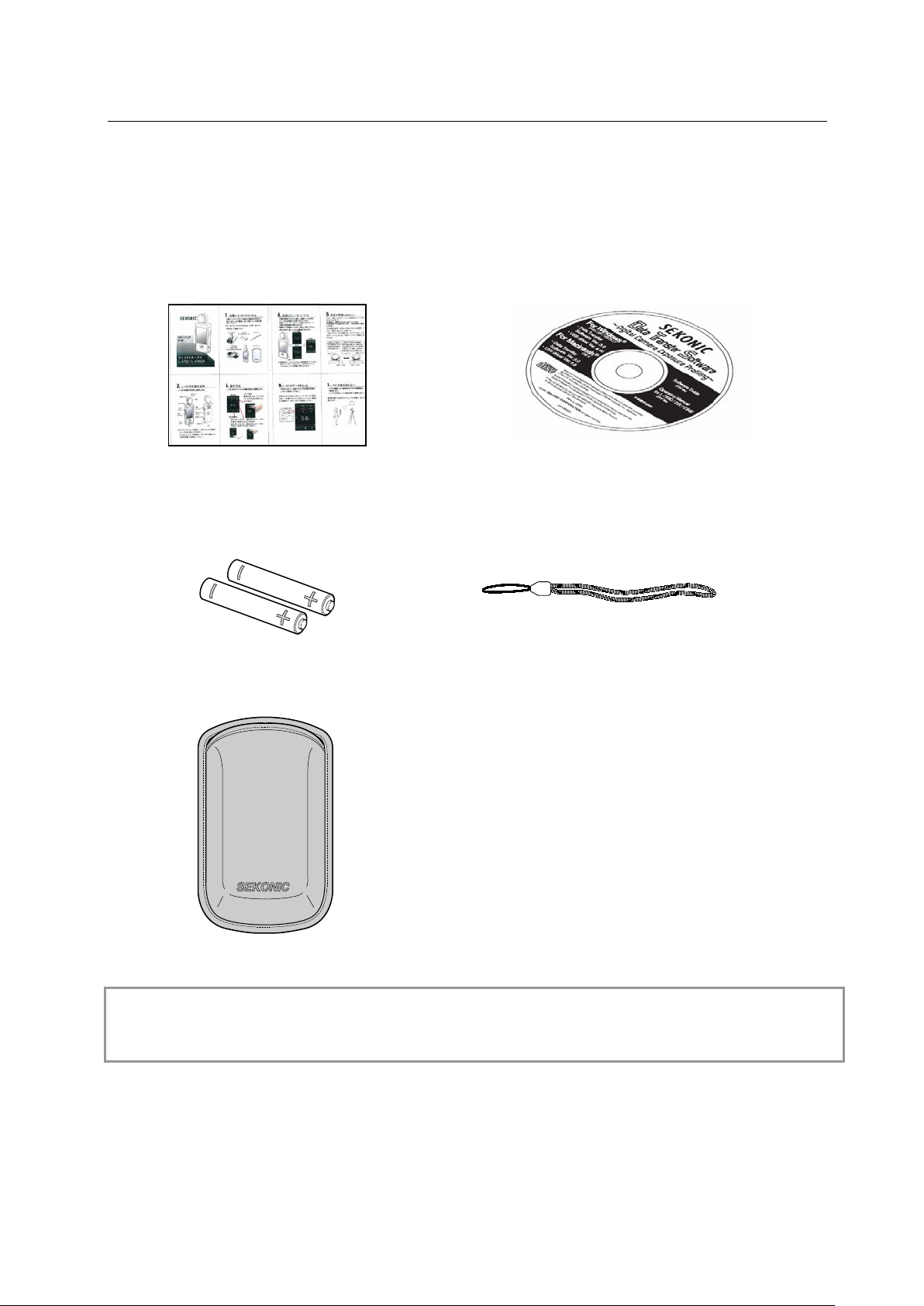
■ Accompanying Accessories
The light meter and accompanying accessories be low are packed together. Please check that all
accessories are included when unpac king.
If, by chance, something i s m issing, please contact the st or e of p ur c hase.
Star t up G uide CD-ROM
(Users’ Manual and Data T ran sfer Softwar e)
Two 4 AAA alkaline batter i es Strap
Soft case
Reference
● Please see “7. Separately Sol d Accessories” (P80) for details about avail able accessories.
3
Page 4
L-478D/L-478DR
Keep the strap out of reach of ba bies and infants, as they may mista kenly wrap
liable to punishment according to the law.
Do not use the product in the rain or l ocat ions where spray and/or moistur e
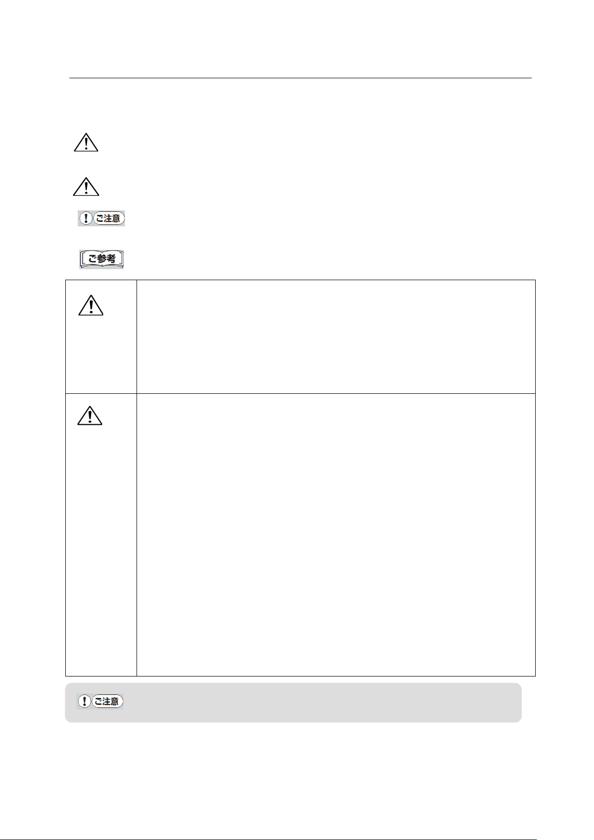
■For Safe and Correct Use
Before using the light meter please be sure to read these s af ety precautions thoroughly and t hen
use the light meter correctly at all times.
War ning
This symbol denotes the possibility of user death or injury if the product is not used
correctly.
Caution
This symbol denotes that there is a possibility of slight to moderate injury to the user
or a likely danger of material damage if the product is not used cor r ect ly.
Caution: This sym bol denotes operating cautions a nd/ or r est r ict i ons. Be sure to read
text accompanying this caution to prevent misoperat ion.
Reference: This symbol denot es information concerning operation references and
related functions. We recommend that you read thi s in formation.
●
War ning
the strap around their nec ks, w hich could lead to the danger of suffo c at io n.
● Do not place batteries in a flame, or shor t-circuit, or dismantle, or heat up, or
recharge (unless the batt er ies ar e rechargeable), as doing so may cause the
batteries to burst, which m ay in turn cause fire, injury and/or peripheral
contamination.
● For L-478DR only: If user intentionally modifies or converts the L-478RD, there
is a risk that doing so may vi ol at e t he Ra di o L aw, which may make the user
Caution
●
occur. Moreover, do not handle the product with wet hands.
Failure to observe the above leads to the danger of electric sho ck when the
product is in “Cord flash mode” (cord connected). Also, the product may become
damaged.
● Never dismantle the main unit of this product.
● Do not play the accompany in g CD-ROM in a music -type CD player, as there is a
risk of hearing damage as well as damage to speakers and/or earphones.
● Use fingers to lightly touch the LC D w hen operating. Do not use sharp obje c t s
such as ballpoint pens or pencils, as doing so may damage t he LCD or cause
damage.
● Do not look directly at the sun via the viewfinder (sold separately), as doing so
may damage eyesight.
● For L-478DR only: This product has certification of conformance to technical
standards as specified lo w power radio equipment in co mp li ance with the Radio
Law (the user is not required to apply for a permit, etc., to use the equi pment).
Nevertheless, the follow ing points must be observed when us ing L-478DR.
・ Do not dismantle and/or convert the product, as doing so is prohibited by law.
・ Do not peel off the label on the rear of the main unit, as using the product
without that label attached is prohibited by law.
・ This product does not conform to radio laws outside of Japan; therefore, this
product may only be used in Japan.
The LCD is covered by a protect ive sheet. Please peel off this sheet before using the
screen.
4
Page 5

L-478D/L-478DR
■Table of Contents
■ Accompanying Accessories ......................................................................................................... 3
■For Safe and Correct Use ............................................................................................................... 4
■Table of Contents .............................................................................................................................. 5
1. Component Names...................................................................................................................... 8
1-1 Main Unit ................................................................................................................................. 8
2. Before Using ................................................................................................................................ 9
2-1 Attaching Strap ........................................................................................................................ 9
2-2 Inserting Batteries ................................................................................................................... 9
2-3 Power ON/OFF ....................................................................................................................... 11
2-4 Checking Battery Capacity ................................................................................................... 12
2-5 Cautions about Battery Replacement during Measuring or the Use of Memory Function
....................................................................................................................................................... 12
2-6 Auto Power OFF Function ..................................................................................................... 12
3. Screen Operations .................................................................................................................... 13
3-1 On-screen Operations ............................................................................................................ 13
3-2 Locking and Releasing of Screen .......................................................................................... 15
3-3 Outline of Screen Transfer .................................................................................................... 15
3-4 Measuring Screen .................................................................................................................. 18
3-4-1 Status/Title Field ............................................................................................................ 18
3-4-2 Measuring Operation/Display Field .............................................................................. 20
3-4-3 Measuring Function Selection Icon ............................................................................... 22
3-5 Information Screen ................................................................................................................ 23
3-6 Toolbox Screen ........................................................................................................................ 23
3-7 Menu Screen ........................................................................................................................... 24
4. Basic Operations ....................................................................................................................... 26
4-1 Basic Operation Flow ............................................................................................................. 26
4-2 Setting Light Receiving System ............................................................................................ 27
4-2-1 Measuring with Incident Light Function (Lumisphere/Flat) ...................................... 27
4-2-2 Measuring with Reflected Light System ....................................................................... 28
4-3 Setting Measuring Mode ....................................................................................................... 29
5. Measuring ................................................................................................................................. 32
5-1 Measuring with Fixed Light Mode ....................................................................................... 32
5-1-1 T (Shutter Speed) Priority Measuring ........................................................................... 32
5-1-2 F (f-stop) Priority Measuring ......................................................................................... 33
5-1-3 TF Priority Measuring .................................................................................................... 33
5-1-4 Illuminance/Luminance Measuring ............................................................................... 33
5-1-5 Measuring when Shooting with Cine or HD Cine Camera .......................................... 37
5-2 Measuring in Flash Mode ...................................................................................................... 40
5-2-1 Measuring in Cord Flash Mode ...................................................................................... 41
5-2-2 Measuring in Cordless Flash Mode ............................................................................... 43
5
Page 6

L-478D/L-478DR
5-2-3 Measuring in Cord Flash Accumulative Mode .............................................................. 44
5-2-4 Measuring in Cordless Flash Accumulative Mode ....................................................... 45
5-3 Measuring with Radio-controlled Flash (for L-478DR only) .............................................. 46
5-3-1 How to Measure Using Radio Control ........................................................................... 46
5-3-2 How to Measure with Radio Control Channels ............................................................ 46
5-3-3 How to Adjust Flash Intensity using Radio Control Screen ........................................ 49
5-3-4 Measuring in Radio Flash Mode .................................................................................... 50
5-3-5 Measuring in Radio Flash Accumulative Mode ............................................................ 51
5-4 What to do when Displayed Range or Measuring Range is Exceeded ............................... 51
5-4-1 When Displayed Range is Exceeded .............................................................................. 51
5-4-2 When Displayed Range is Exceeded .............................................................................. 52
6. Functions ................................................................................................................................... 53
6-1 Memory Function ................................................................................................................... 53
6-1-1 Memory ............................................................................................................................ 53
6-1-2 Memory Recall ................................................................................................................. 54
6-1-3 Memory Clear .................................................................................................................. 55
6-2 Mid. Tone Function ................................................................................................................ 56
6-2-1 Setting Measuring Value as Mid. Tone .......................................................................... 56
6-2-2 Setting Memorized Measuring Value as Mid. Tone ...................................................... 56
6-2-3 Mid. Tone Modification ................................................................................................... 57
6-2-4 Mid. Tone Clearing .......................................................................................................... 57
6-2-5 Mid. Tone Recall .............................................................................................................. 58
6-3 Average Function ................................................................................................................... 59
6-4 Monitor Function ................................................................................................................... 60
6-5 Filter Compensation Function .............................................................................................. 62
6-5-1 Setting Filter Numbers and Compensation Values ...................................................... 62
6-5-2 Selecting Filter ................................................................................................................ 64
6-5-3 Deselecting Filter ............................................................................................................ 64
6-6 Functions by Menu Selection ................................................................................................ 65
6-6-1 Exposure Profile Selection/Editing Function ................................................................ 65
6-6-2 Analog Scale Switching ................................................................................................... 67
6-6-3 Calibrated Compensation Value Function .................................................................... 67
6-6-4 Custom Setting Function ................................................................................................ 68
6-6-5 Frame rate User Setting ................................................................................................. 70
6-6-6 Shutter Opening Angle User Setting ............................................................................. 71
6-6-7 Filter User Setting .......................................................................................................... 73
Reference ............................................................................................................................... 75
6-6-8 Exposure Profile Editing Function ................................................................................ 75
6-7 Hardware Setting Screen ...................................................................................................... 78
7. Separately Sold Accessories ........................................................................................................ 80
6
Page 7

L-478D/L-478DR
8. Registered Filters......................................................................................................................... 82
9. Specifications ................................................................................................................................ 83
10. Usage Precautions ..................................................................................................................... 85
11. About Aftercare Service ............................................................................................................. 86
7
Page 8
L-478D/L-478DR
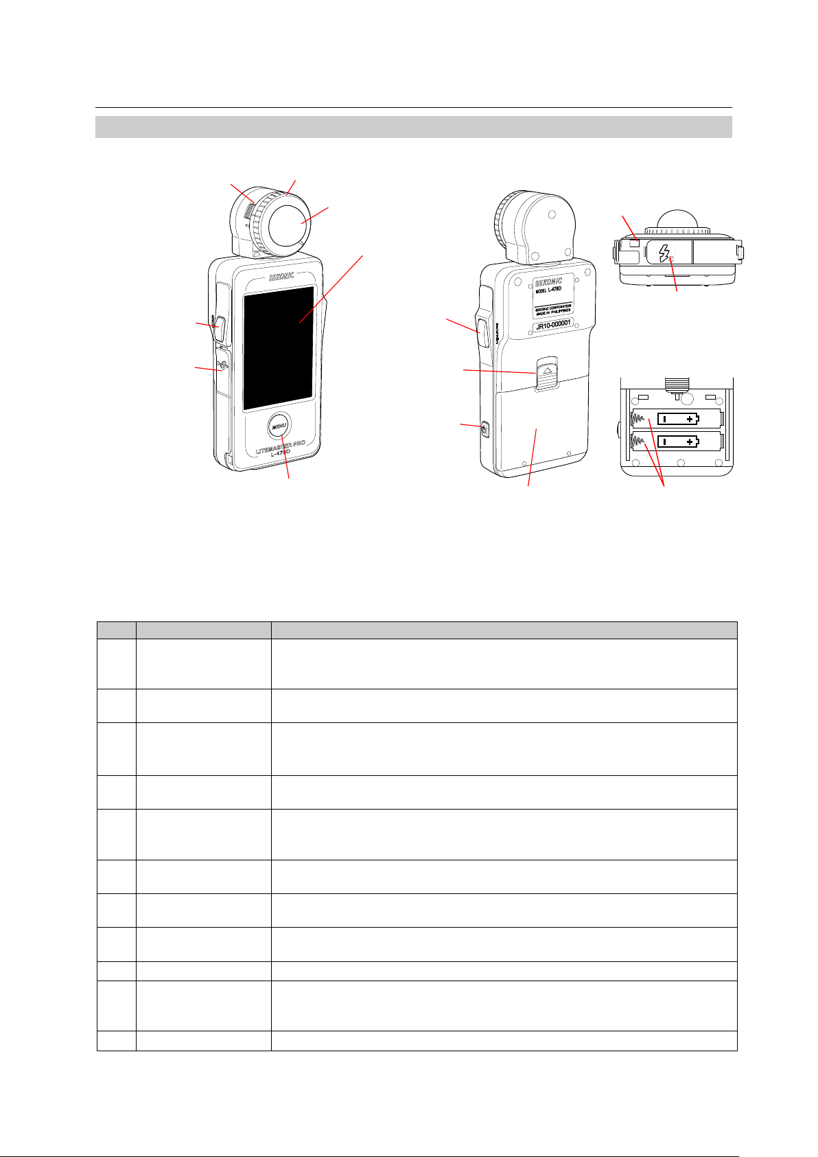
No.
Name
Explanation
Lumisphere
release lever
Hold this down when rem oving the lumisphere from the main un it .
Lumisphere
retracting ring
Use this to switch betwee n ext ended and retracted lumispher e. ( See
P23 for details.)
Lumisphere
Use the Lumisphere retracting ring to switch between extended and
Can be freely rotated through 270°to receive light.
Touch panel
This displays measurin g scr eens and setting screens. Touch this panel
to perform settings and oper at ion s . ( See P11 for details.)
Memory button*1
This memorizes the current measuring value in memory.
accumulated measuring values.
USB connector
This is for connecting to a computer installed with the Data Trans fer
Software. USB terminal is a 5-pin mini B connector.
Menu button
Press this to enter Menu mode fr om any of the screens.
Press again to return to the previous screen. (See P21 for det ai ls. )
Menu button*1
Press this when the Measur ing s c r een is displayed to implement
measuring.
Battery cover lock
This is the battery cover lock.
Power button
User this to turn power ON and O FF.
OFF.
Battery cover
This is the battery cov er.
Battery holder
Strap eyelet
②
Lumisphere retract
④
Touch panel
⑩
⑤
※
1
⑧
Measuring button
※
1
⑥
USB
connector
⑨
Battery cover
lock
⑪
Battery cover
Rear
Front
③
Lumisphere
① Lumisphere release and lock release
Menu button
1. Component Names
1-1 Main Unit
Memory button
⑦
※1 Using Custom Setting Function (see P74), the Memory butt on ⑤ and the Measuring
button ⑧ can be swapped from left to right.
The following are the main unit components and their fu nc t i ons.
ing ring
⑫
⑬ Synchro terminal
Inside battery case
Power button
⑭
Bottom
①
release and lock
②
③
④
⑤
⑥
⑦
⑧
⑨
⑩
⑪
(See P24 for details. )
retracted lumisphere.
Press this during measur i ng in accumulative mode to clear t he
Hold this button down (ap pr oxi m at ely one second) when turning pow er
8
Page 9
L-478D/L-478DR
Strap ey el et
This is for attaching t he st r ap ac cessory.
Synchro terminal
A sy nchr o c or d (s old separately) is plugge d into t his terminal when
measuring in a flash-conn ected mod e.
Battery holder
This is for housing the batt er ies. Be sure to insert batteries according
to polarity.
⑫ストラップ掛け
⑪電池カバー
⑨電池カバーロック
爪
⑭電池ホルダー
⑫
⑬
⑭
※1 Using Custom Setting Function, the Memory but t on ⑤ and the Measuring button ⑧ can be
swapped from left to r ight . ( See P 56 f or details.)
2. Before Using
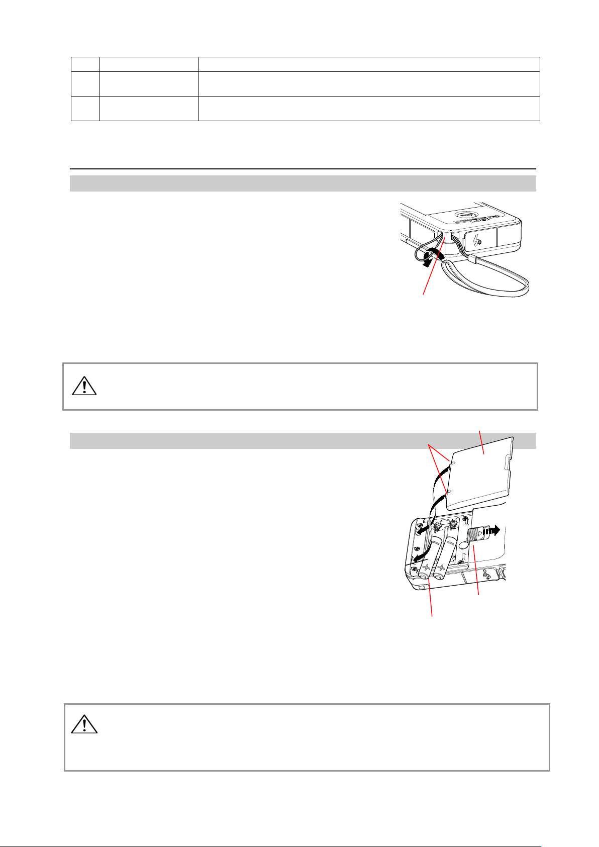
2-1 Attaching Strap
1) Attach the st r ap accessory by passing t he small end loop through the
eyelet ⑫.
2) Pass the end of t he st r ap t hr ough the small end loop.
⑫ Strap eyelet
Keep the strap out of reach of ba bi es and infants, as they may mistakenly wrap the
War ning
strap around their necks, which could lead to the danger of su ffoc at i on.
2-2 Inserting Batteries
1) Requires t w o 4 AAA alkaline batteries.
2) Slide the batt ery cover lock ⑨ in the
direction of the arrow and r em ove the
cover ⑪.
3) Insert the batt er ies, observing the
polarity with the + and – symbols.
※ Insert both batteries with + and – aligned as
shown in the diagram.
4) Insert the two prongs on the cover ⑪
and then press down cove r to close.
⑪ Battery cover
Clasping prongs
⑨ Battery cover lock
⑭ Battery holder
Do not place batteries in a flame, or short-circuit, or dis m ant le, or heat up, or
War ning
recharge (unless the batt er ies ar e rechargeable), as doing so may cause the
batteries to burst, which m ay in turn cause fire, injury and/or peri pheral
contamination.
9
Page 10

● Insert batteries from the minus (-) end. When removing batteries, pull out from plus
Caution
(+) end.
● Do not use different brands of battery. Also, do n ot use new and used batteries
together.
● Remove batteries if the light meter is not going to be used for a prolonged period.
Batteries can leak and may adversely affect t he main unit.
L-478D/L-478DR
10
Page 11
L-478D/L-478DR
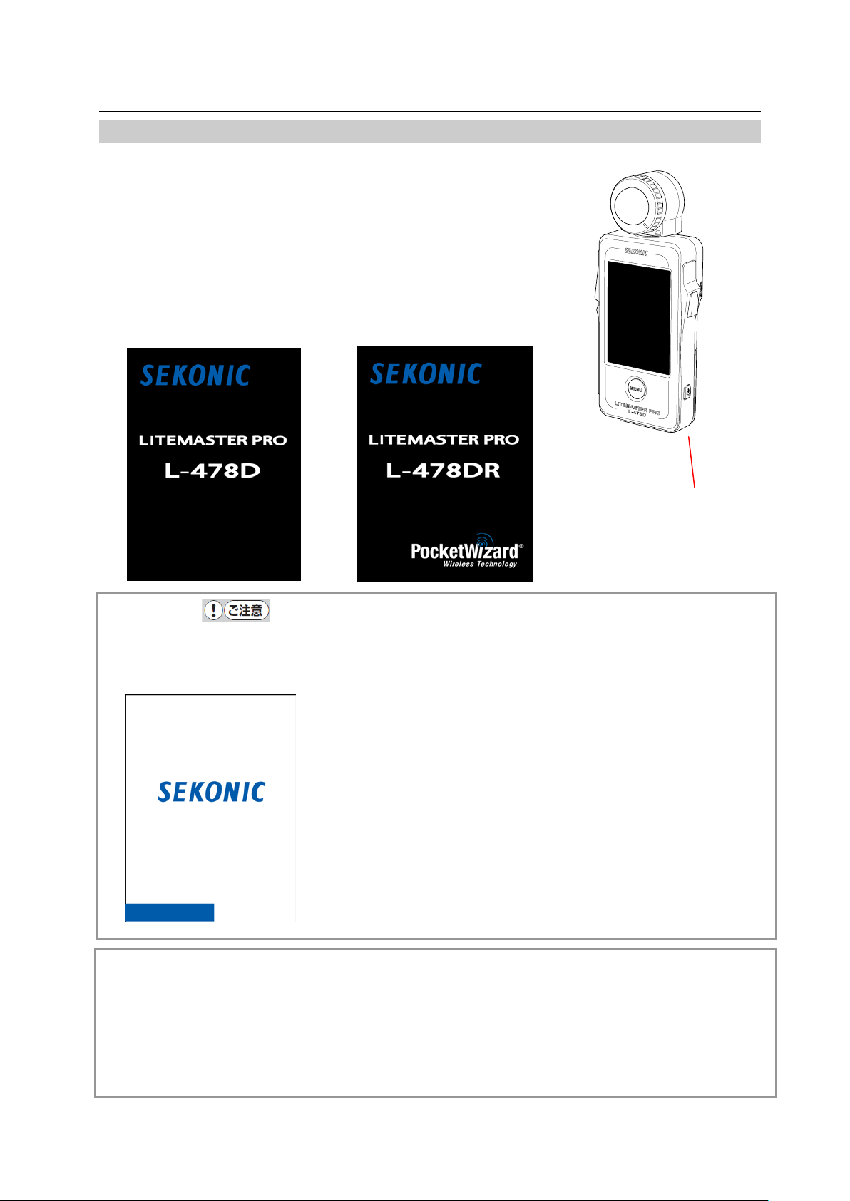
Title Screens
L-478D
L-478DR
Logo Screen
⑩
Power button
2-3 Power ON/OFF
Power ON: Press the Power button ⑩.
The main unit will turn ON, and af t er t he title
screen has been displayed, the Measuring
screen will be displayed.
Power OFF: Press the Power button ⑩ for one second or
longer. The main unit will turn O FF and the
display will close.
Caution
● Directly after replacing batteries, a white screen with the SEKONIC logo in blue will be
displayed, followed by t he appr opriate title screen above.
(※An L-478D/DR memory check is be ing executed while the blue
bar graph is moving when t he Logo s cr een is displayed, so
please do not turn OFF the power, as doi ng so may cause
damage.)
Reference
● If there is no display on the LCD (touch panel) once the power has been turned ON, check
battery capacity as well as whether or not batteries have been ins erted with polarities in
wrong direction.
● The setting values and measuring values are memorized even w hen t he power is turned OFF
and they will be redisplayed when t he power is turned ON again. Memorized setting values and
measuring values also ar e saved even when the batteries ar e r emoved.
11
Page 12
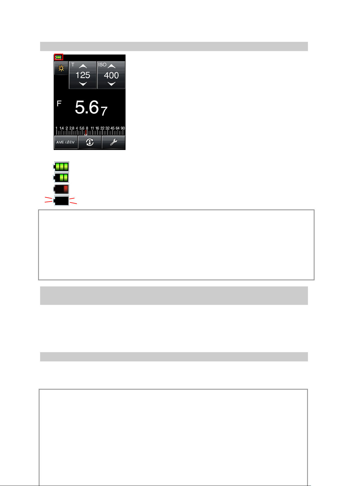
2-4 Checking Battery Capacity
When the power button is ON, the battery power indicator is displayed in the top left of the LCD.
Battery power level is good.
Battery power level is sufficient.
Battery power level is low. Have spar e batteries ready.
L-478D/L-478DR
If blinking, replace batteri es immediately.
Reference
● When there is no battery power, and the power is turned ON, the screen may appear and then
abruptly close, but this do es not m ean the main unit is damaged. Ple ase insert new batteries. We
recommend that you hav e spar e bat t er i es r eady at all times.
● With consecutive measuring, t he bat t er y lifespan for this product at room te m perature is
approximately ten hours (Sekonic test conditions for alkaline batteries).
● The batteries packed with t he pr oduct at time of purchase may have a short er l if espan.
2-5 Cautions about Battery Replacem ent during Measuring or the
Use of Memory Function
1) Always turn OFF the power befor e r eplacing batteries.
2)If an abnormal display (one t hat has not been set, etc.) appears on the LCD after battery
replacement or during me asur i ng, or the light meter will not oper at e even when an operation
button is pressed, remov e the batteries, wait ten seconds or longer and t hen reinsert them.
2-6 Auto Power OFF Function
The product is designed to save power, so al l dis plays will automatically close and the power
will turn OFF if approximat ely five minutes elapse from the last button operation.
Reference
● Even if the Auto Power OFF Function co m es i nto action and the power is turned OFF, the set
values and indicated values w il l be sav ed and then redisplayed once the power is turned ON
again.
● The Auto Power OFF time can be selected at the Custom Setting sc r een. Enter Custom
Setting mode and under setting number 21 select one of the foll ow ing 0: 5 min (default), 1: 10
12
Page 13
L-478D/L-478DR
Measuring Mode Selection Screen
Scroll bar
min, 2: 20 min, 3: Cancel Auto P ow er O FF. ( S ee P56 for details.)
● When Power button ⑩ is held down continually, the power will initially come ON but then
automatically turn OFF a fter appr oximately one minute. (This means battery depletion can be
avoided even if the Power but ton ⑩ is held down during transportat i on. )
3. Screen Operations
The screen is a touch panel, so you can use your fingers to touch buttons in order to select desired
menus and items.
※ Liquid Crystal Backlight
Once the power is turned ON, t he backlight will be lit at all times. However, it will dim s o
that it does influence mea sur ing values during measuring or c or dless flash standby.
3-1 On-screen Operations
Touch the icons on screen to perform operations.
The following are the icon types.
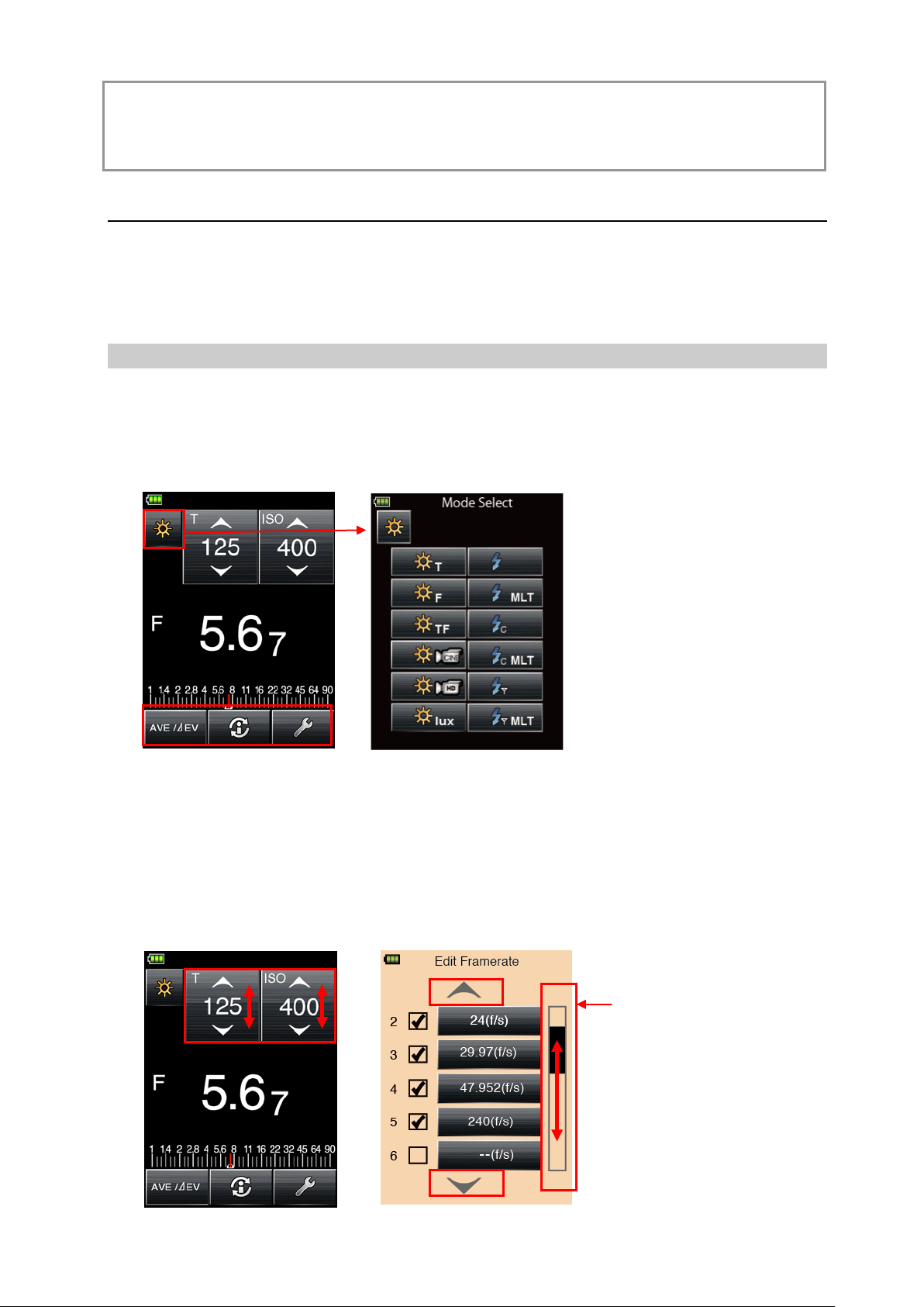
(1) Measuring Mode Icon
Touch the Meas ur ing mode icon to display the Measur ing Mode Selection screen. Touch any icon
to switch to that Measurin g mo de. ( See P25 for details.)
Example of Measuring Screen
(2) Setting Value Change/Item Selection Icon
Touch Operation:
Touch the up arrow (▲)to increase the value or change up to the next item.
Touch the down ar row (▼) to decrease the value or change down to the next item.
Slide Operation:
Slide numbers and items up and down with your fingertip to change display contents.
At screens with a scroll ba r displayed on the right side, you c an slide that scroll bar to
change screen contents.
Example of Measuring Screen Example of Edit Frame rate Selection Screen
13
Page 14
(3) Radio Button
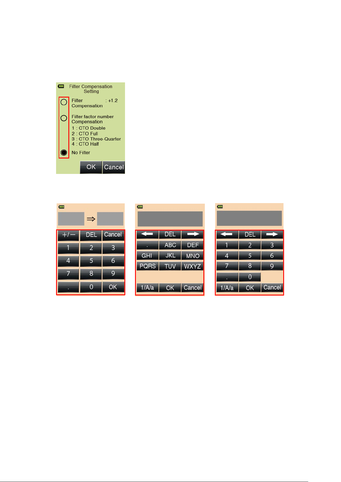
Filter Compensation Setting Screen
Touch the Radi o but ton and the item on the right of the Radi o but ton is selected.
Only one item can be select ed.
(4) Number/Alphabet Input Button
L-478D/L-478DR
Example of Value Input Screen Example of Alphabet Input Screen Example Number Input Screen
Inputting Values (Value Input Scre en):
0-9、Decimal point、+/-: Display input value at top of screen.
Enter: Confirms input value and returns to previou s scr een.
DEL: Deletes input value.
Cancel: Cancels input and returns to previous screen.
Inputting Alphabet and Nu m be rs (Alphabet Inp ut Screen and Num ber Input Screen):
1/A/a: Switches between Tenkey input/Uppercase/Lowercase.
ABC,abc,0-9, Decimal Point: Display input value at top of screen when touched.
Repeated pressing of the same butt on will change the alphabet
character to be input.
← →: Shift input position.
OK: Confirms input v alue and returns to previous screen.
DEL: Deletes input value.
Cancel: Cancels inputting and returns to previous screen.
14
Page 15
L-478D/L-478DR
⑦ Menu button
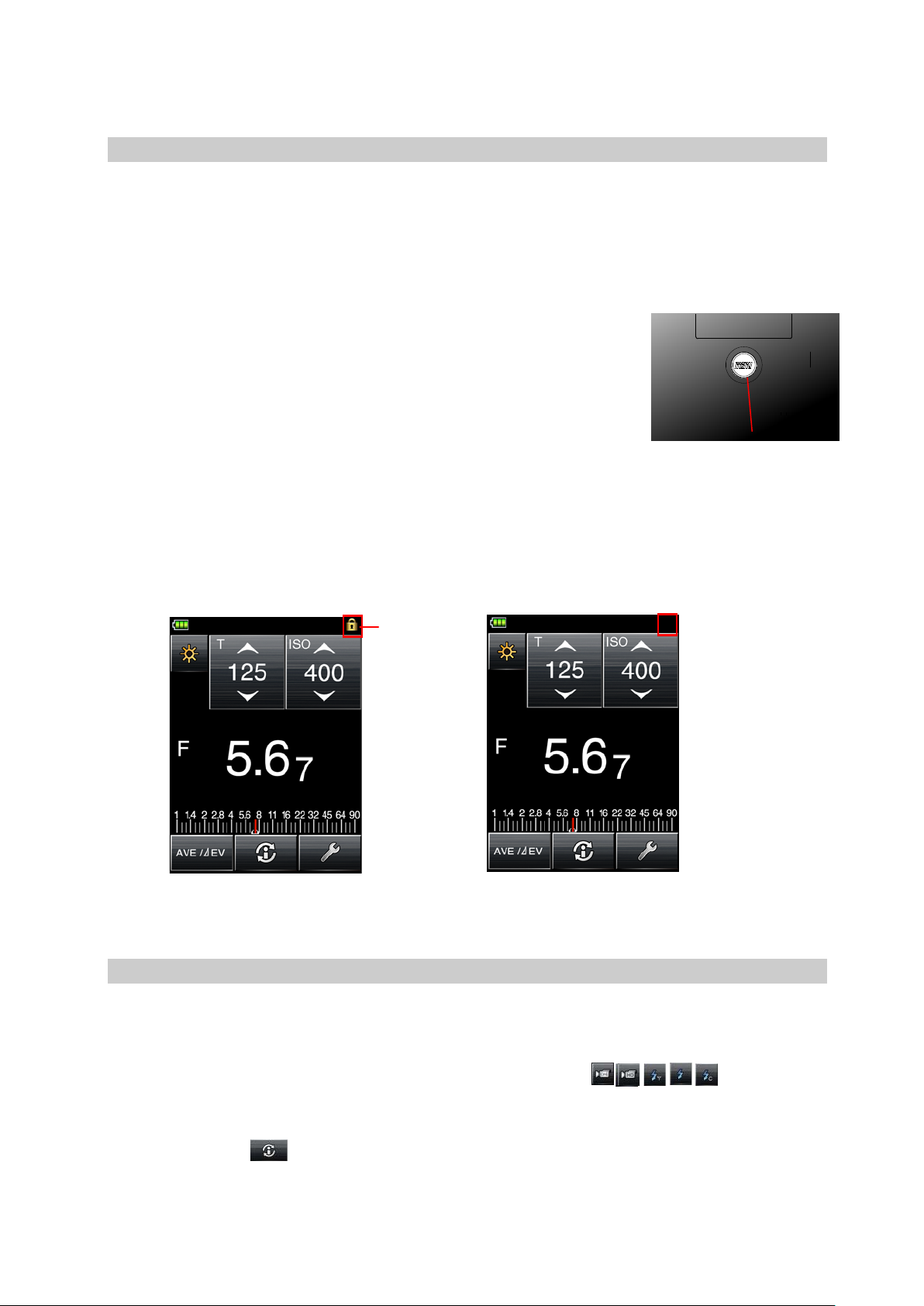
Screen lock
Lock Released
Locked
3-2 Locking and Releasing of Screen
The screen can be locked t o pr event unforeseeable misoperations, etc.
Touch operation of all screens is prohibit ed w hen locked (the lock icon is displa yed at the top of the
screen). Note however that t he M em or y button ⑤, Measuring button ⑧ and Power button ⑩
will be operational even i f lock is ON.
Lock status will be maintained even when power is turned OFF.
Setting Lock:
Press and hold down Menu but t on ⑦ to lock the screen
(the lock icon will be displ ayed at the top right of the screen).
Buttons and icons on the LCD (touch panel) cannot be
operated while the lock is ON. M or eover, pres si ng t he Menu
button ⑦ to open the Menu Functions is not possible.
※ This operation can be executed at t he M easuring screen.
Releasing Lock:
Press and hold down again t he M enu button to release the locked screen ( t he screen locked
icon will close.)
icon
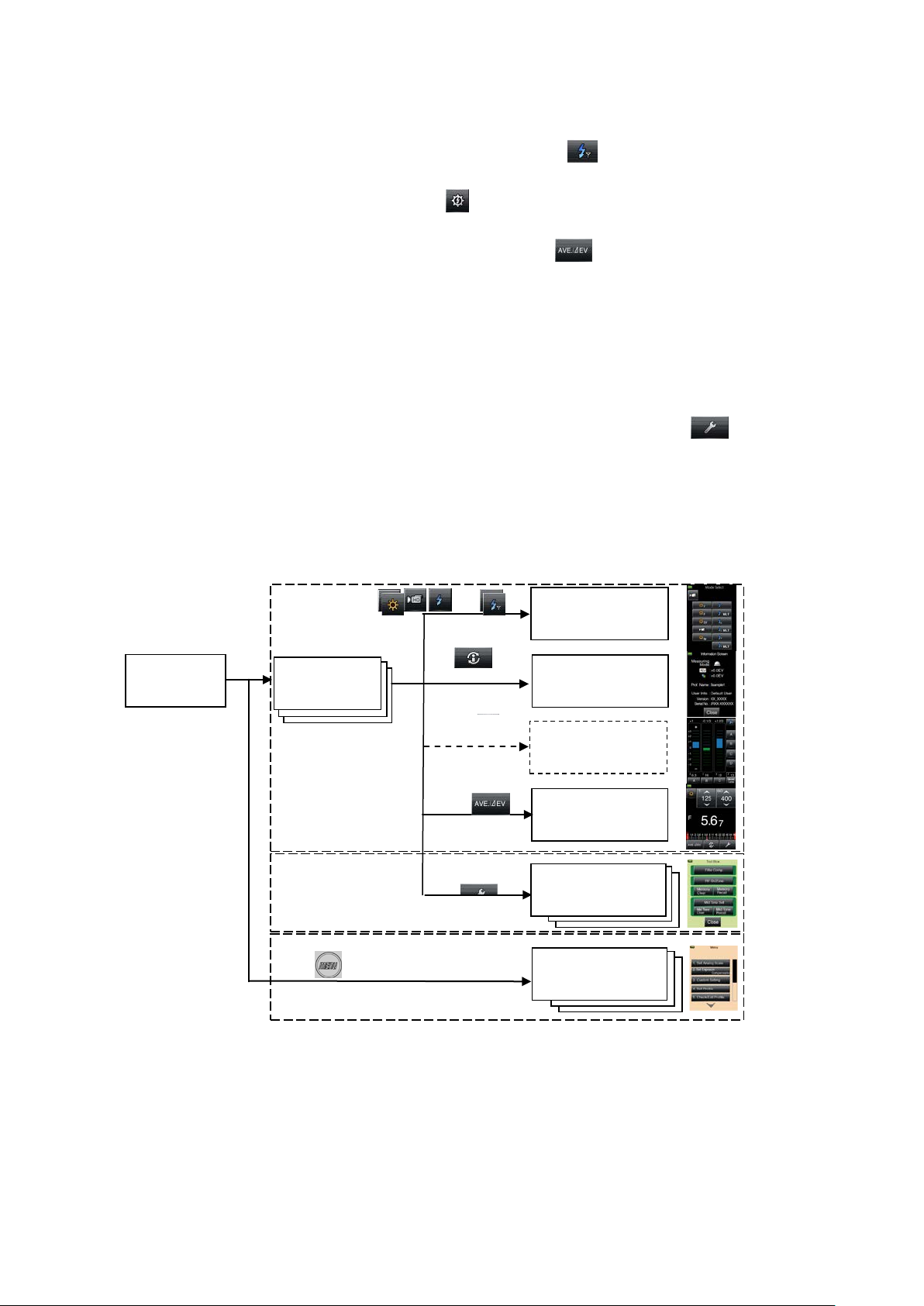
3-3 Outline of Screen Transfer
(1) Measuring Screen (Background color: Black)
1) When turning ON the power , the measuring screen will be disp layed using the setting
values that were current w hen t he power was turned OFF last.
,
,
,
,
To select another Measuri ng sc reen, touch a mode icon (,
select the desired Measur ing screen at the Select screen.
2) To find out detailed information about the currently display ed M easuring screen, touch the
Information icon (
). (See P20 for details.)
3) To perform Radio Control, press the Menu button ⑦ at the Exposure Metering screen and
15
)and then
Page 16
then select item 0 (ON) for Set t ing Number 14 (Radio Control).
Power ON
Measuring Mode
Information
Radio Control
⑩Power button
Info icon
Radio
Toolbox
⑦Menu button ※1
3-4
screen
3-7 Menu screen
3-6
Measuring
Toolbox screen
Menu screen
Measuring screen
Average
icon
Measuring Mode Icon
Next, touch the Measuring mode icon at the top left of the M easuring screen to display
the Measuring Mode Select screen and then touch the
Radio mode. (See P41 for details.)
Finally, touch the Radio Cont r ol i con(
)at the top left of the Measuring screen. (See
P38 for details.)
4) To use the Average Fu nct ion, touch the Average icon (
The Average Function can average out up to nine memorized readings and display the
average.
This function can be used with the following modes: Fixed Light Shutter Speed priority,
Stop priority, TF priority and Flash (cord, cordless, radio trigger), but note that it cannot be
used with Accumulative mode.
(2) Toolbox Screen (Background color: Green)
L-478D/L-478DR
icon to display the Flash
). (See P49 for details.)
To make various settings for the current Measuring screen, touch the Toolbox icon (
)at the
Measuring screen. (See P20 for details.)
(3) Menu Screen (Background color: Light orange)
Press the Menu button on t he ma in unit (while working in any screen) t o display the Menu
screen (※1).
At the Menu screen, you can set al l men u operations for this light meter. (See P21 for details.)
Measuring
, , ,
, ,
Select Screen
screen
Control icon
screen
screen(L-478DR)
(Average)
Toolbox screen
icon
※1 If you press the Menu button while working at another Setting screen,
the settings in mid-operation will be interrupted and the Menu List
displayed.
※2 This screen is display ed only when the Flash Radio mode is be ing used
(for L-478DR only).
16
Page 17
L-478D/L-478DR
Power button
⑦Menu button
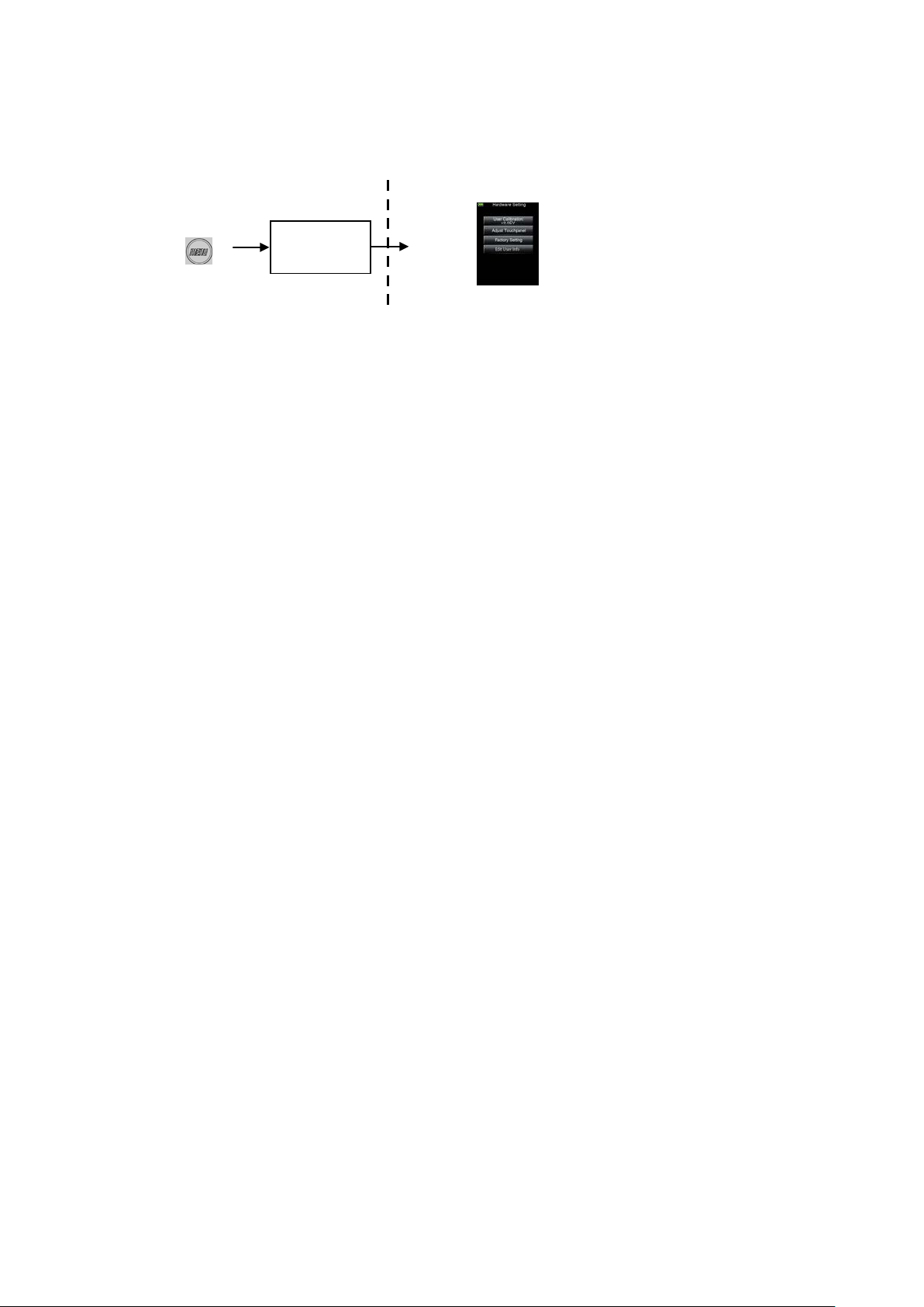
6-7 Hardware Setting Screen
Power ON
(4) Hardware Setting Screen
Hold down the Menu button ⑦ and then turn ON the power to display the Hardware Setting
screen. (See P62 for det ails.)
⑩
17
Page 18
L-478D/L-478DR
No.
Icon Name
Explanation
Indicator Display
compensation
actually measured exposure readings.
symbol.
measured exposure read ings.
for details.)
Status/Title field
Measuring function selection icon
Measuring operations/Display area
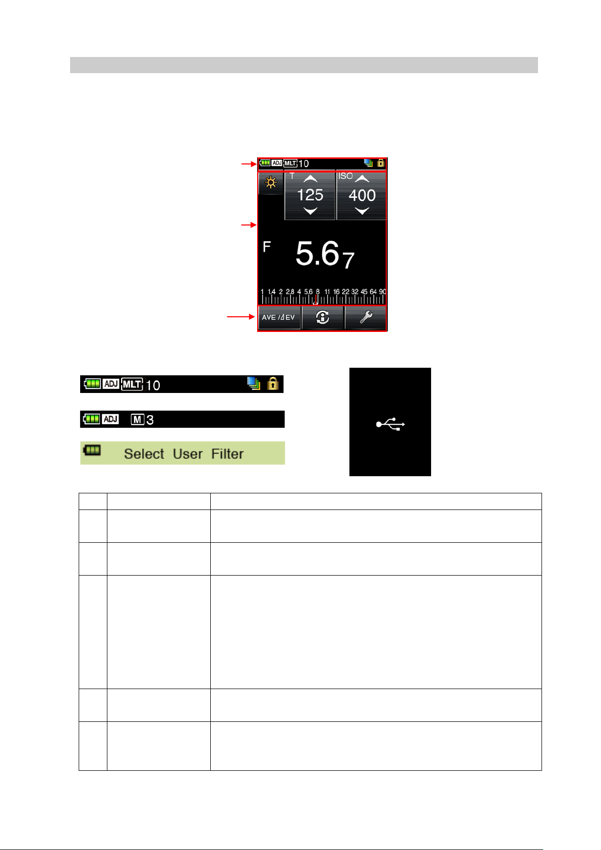
① ② ③ ④ ⑤ ⑥ ⑦ ⑧ Example of Fixed Light Screen
3-4 Measuring Screen
When the power is turned O N, t he Title scree n will appear , followed by the Measuring scre en.
Subject measuring c an be performed at the Measuring screen.
Basic Configuration of the Measuring Screen
3-4-1 Status/Title Field
① Battery Power
② Calibration
③ Accumulative
mode/Accumulativ
e count (multi)
This displays battery c apacity in four stages. (S ee P11 for details.)
This is displayed when ca l ibrat ion compensation is performed on
This is displayed when an Accumulative mode is selected. I t will be
displayed with the followin g M easuring screens.
・ Cordless Flash Accumulative
・ Cord Flash Accumulative
・ Flash Radio Accumulative Mode (for L-478DR only)
Accumulative count (up to 99) is displayed to the right of the MLT
④ Filter compensation This is displayed when filter compensat i on is performed on actually
⑤ Screen lock This is displayed when screen is locked. Operations cann ot be
performed on the touch panel when the screen is locked. ( See P11
18
Page 19

L-478D/L-478DR
main unit to a computer.
symbol.
screen.)
⑥ USB display
This is full-screen displayed when USB cable is used to conne ct the
⑦ Memory count This displays the number of memorized readings.
The memory count (up to 9) is di spl ayed to the right of the M
⑧ Title This is the screen title. (Title is displayed except for Measurin g
19
Page 20
L-478D/L-478DR
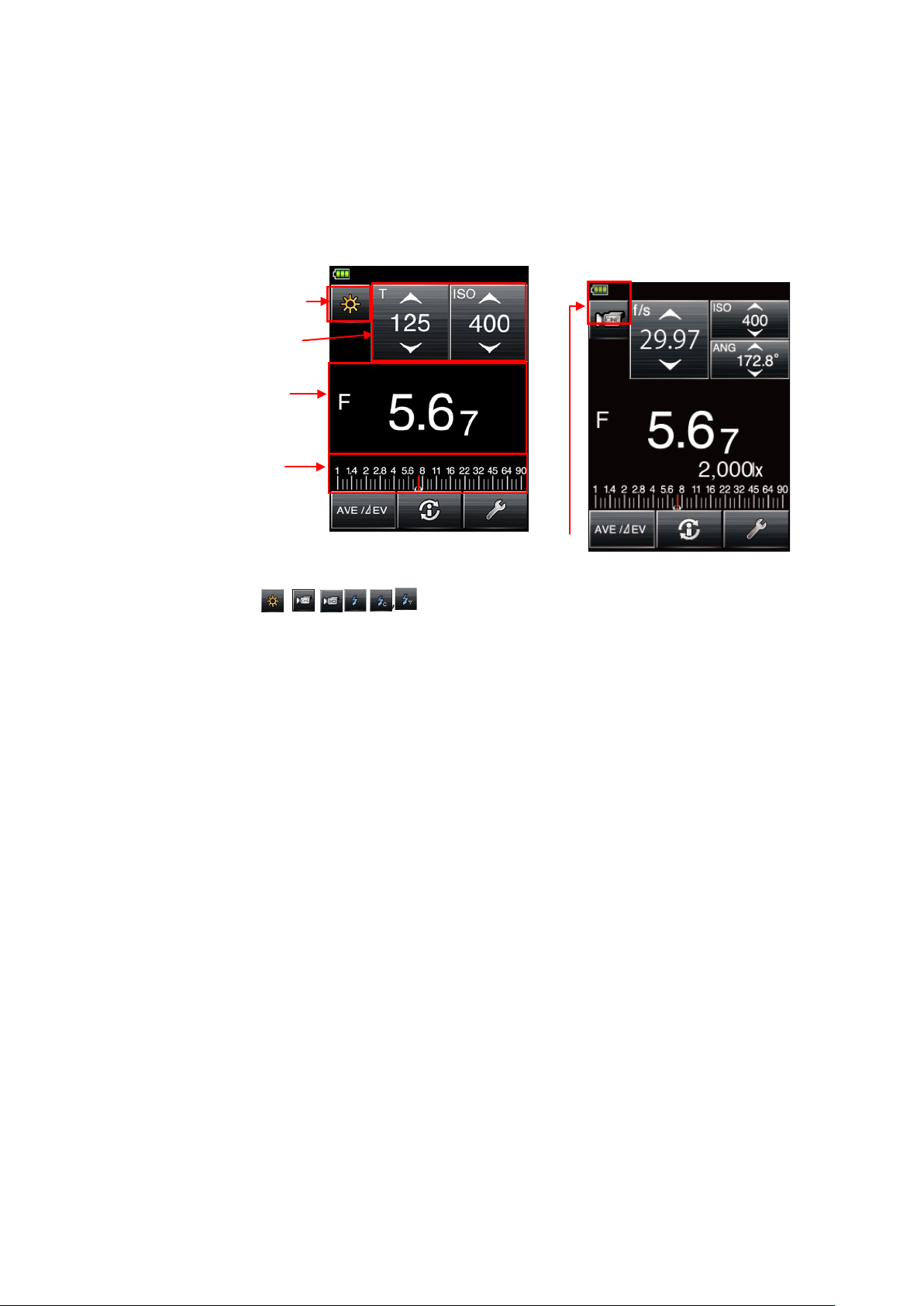
(4) Analog scale
(3) Measuring value/Setting
(2) Setting icons
(1) Measuring mode ic
Example of Screen for
fixed light
(1) Measuring mode icon[CINEmode]
3-4-2 Measuring Operation/Display Field
Measuring Operation/ D isplay Field is configured o f the following sections.
・ Measuring mode icons
・Setting icons
・ Measuring value/Settin g display field
・Analog scale
Cine Mode Screen
display field
(1) Measuring Mode
Touch a mode (
, , , ,,
)at the top left of the Measuring screen to display the
Measuring Mode Selecti on screen, where any of the Measur ing modes can be selected.(See
P29 for details.)
20
Page 21
L-478D/L-478DR
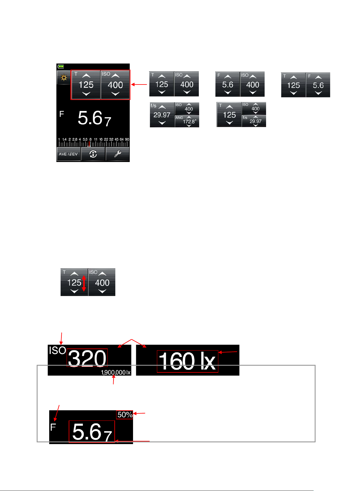
Measuring values
Measuring value unit: T (shutter speed), F (f-stop), ISO (ISO film speed)
Additional info for measuring value
Measuring mode information display
・
independent
・fc:
independent
display
・
independent display
・
display
Measuring value
Measuring value unit:F (f-stop)
(2) Setting Icons
Use this to set functions like s hut t er speed and f-stop. Setting values are displayed within the icons.
The displayed cons will change in accordance with the Measuring mode being used.
Shutter Speed Priority
f-stop Priority
TF Priority
CINE mode HD CINE mode
The alphabet letter in the top le f t of the set icon denotes setting contents.
・ T : Shutter speed
Shutter speed is displayed in the following way.
30m(30 minutes)、8s(8 seconds)、125(1/125 of a second)
・ ISO : ISO film speed
・ F : f-stop
・ ANG : Shutter opening angle
・ f/s : Frame rate (= cine frame rate)
Set Icon Operation:
V alue increases when up ar r ow (▲)is touched.
V alue decreases when do w n ar r ow (▼)is touched.
Slide the icon number up or down with y our finger t i p to increase or decrease the r eading.
(3) Measuring value/Setting display field
This displays information such as measured values and measuring unit s.
Example: 1,900,000lx
Component ratio display
・Component ratio display: Flash component ratio is numerically displayed
in 10% steps for overall intensity.
lx,:Fixed light illuminance lx
display
Fixed light illuminance fc
cd/㎡:Fixed light luminance cd/㎡
fl:Fixed light luminance fl independent
21
Page 22
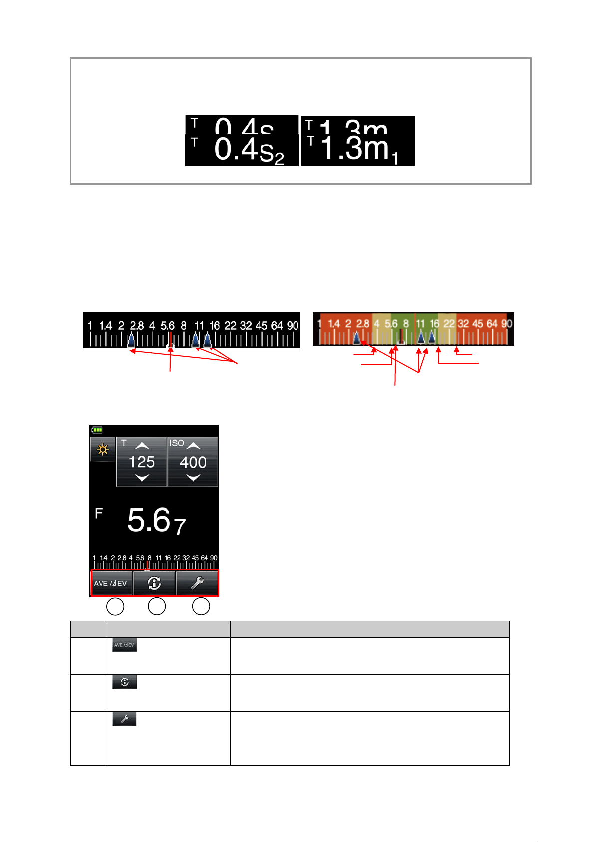
Reference
No.
Icon
Explanation
Use this icon when using the Average Function or Monitor
Monitor Function (P60) for details.
This displays detaile d information about the Measuring
(P20) for details.
Use this to proceed to the Toolbox screen related to the
1 2 3
Tolerance range[-]
Reproduction field [-]
Tolerance range[+]
Reproduction range [+]
Measuring value cursor
Memory value cursors
Measuring value cursor
Memory value cursors
Fraction
hidden
Fraction
displayed
The fractions of the measuring values can be hidden by changing setting at the Custom Setting Function.
Display setting number 2 (fraction display) and then select 0 (ON) to display fraction and 1 (OFF) to hide
fraction. (See P68 for details.
)
(4) Analog Scale
Depending on the Measur ing mode, the following values will be displayed in the scale.
・F value, T value, EV value (for incident), EV value (for reflected), illuminance lx (lux),
illuminance fc
The following is a scale displ ay example.
Scale Display (T val ue) Exam pl e
[Display when measuring](except for mid tone setting) [Display when measuring] when
reflected light mid tone is s et
3-4-3 Measuring Function Selection Icon
Press any one of the icons to execute that function.
L-478D/L-478DR
①
②
③
Average icon
Information icon
Toolbox icon
Function. See 6-3 Average Function (P59) and 6-4
screen currently selected. See 3-5 Information Scre en
current type of measuring. See 3-6 Toolbox Screen (P20)
for details.
22
Page 23
L-478D/L-478DR
No.
Item
Explanation
receiving mode
/reflected light
.
compensation
value.
1 2 3 4 5 6 7
8
5
6
1
2
3
4
7
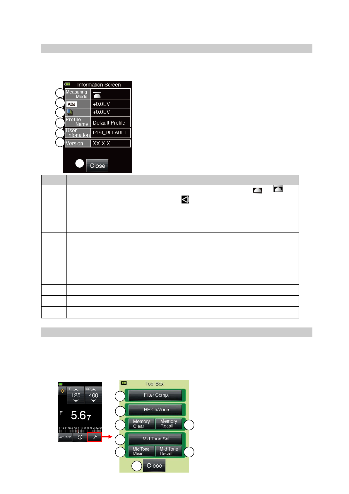
3-5 Information Screen
This displays detaile d information set for the light met er but not displayed in the Measuring
screen.
① Display of light
② Display of amount of
calibration
③ Display of amount of
filter compensation
④ Displays camera
exposure profile
⑤ User information Displays user informatio n.
⑥ Version inf ormation Displays firmware ver sion.
⑦ Close Returns to previous meas ur ing screen.
Displays selection st at us of incident light(
( )
Displays user-set calibration c ompensation value.
See P55 for details on s et t ing calibration compensation
Displays user-set filter comp ensation value.
See P51 for details on setting filter compensation
value.
Displays camera exposure profile name. See P25 for
details on selecting camera exposure profile name.
or
3-6 Toolbox Screen
The following settings can be made by selecting the Toolbox from the Measuring scr een.
・Filter compensation sett ing
・Memory recall, memory clear
・Mid tone set, mid tone clear, mid tone recall
・Radio trigger channel setting (for L-478DR only)
)
23
Page 24
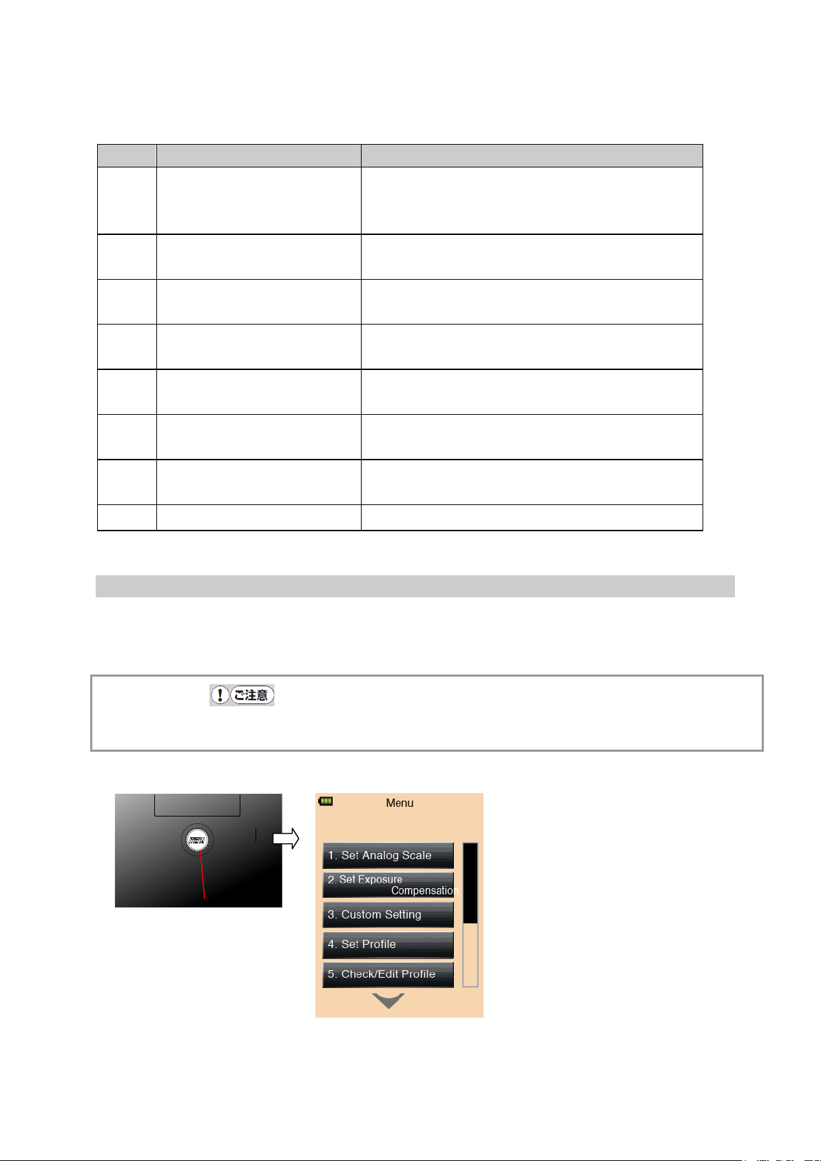
No.
Item
Explanation
for L-478DR only)
(See P38 for details. )
details.)
P45 for details.)
for details.)
details.)
details.)
⑦ Menu button
Menu Screen
① Filter compensation Displays Filter compens at ion setting screen. (See
P51 for details.)
L-478D/L-478DR
② Radio trigger channel
Displays Radio Trigger Channe l S et t ing screen.
(
③ Memory clear Displays Memory Clear screen. (See P44 for
④ Memory recall Displays Memory Recall Selection screen. (See
⑤ Mid tone set Displays M id . Tone Set screen (See P46 and P47
⑥ Mid tone clear Disp lays Mid. Tone clear screen. (See P47 for
⑦ Mid tone recall Displays Mid. Tone Recall screen. (Se e P48 for
⑧ Close Returns to previous Measuring screen.
3-7 Menu Screen
Press the Menu button ⑦ on the main unit to display the Menu screen.
Press the Menu button ⑦ again to return to the previous screen.
Caution
● If you press the Menu button ⑦ when another setting screen is displayed, t he settings in
mid-operation will be interrupt ed and the Menu List displayed.
24
Page 25
L-478D/L-478DR
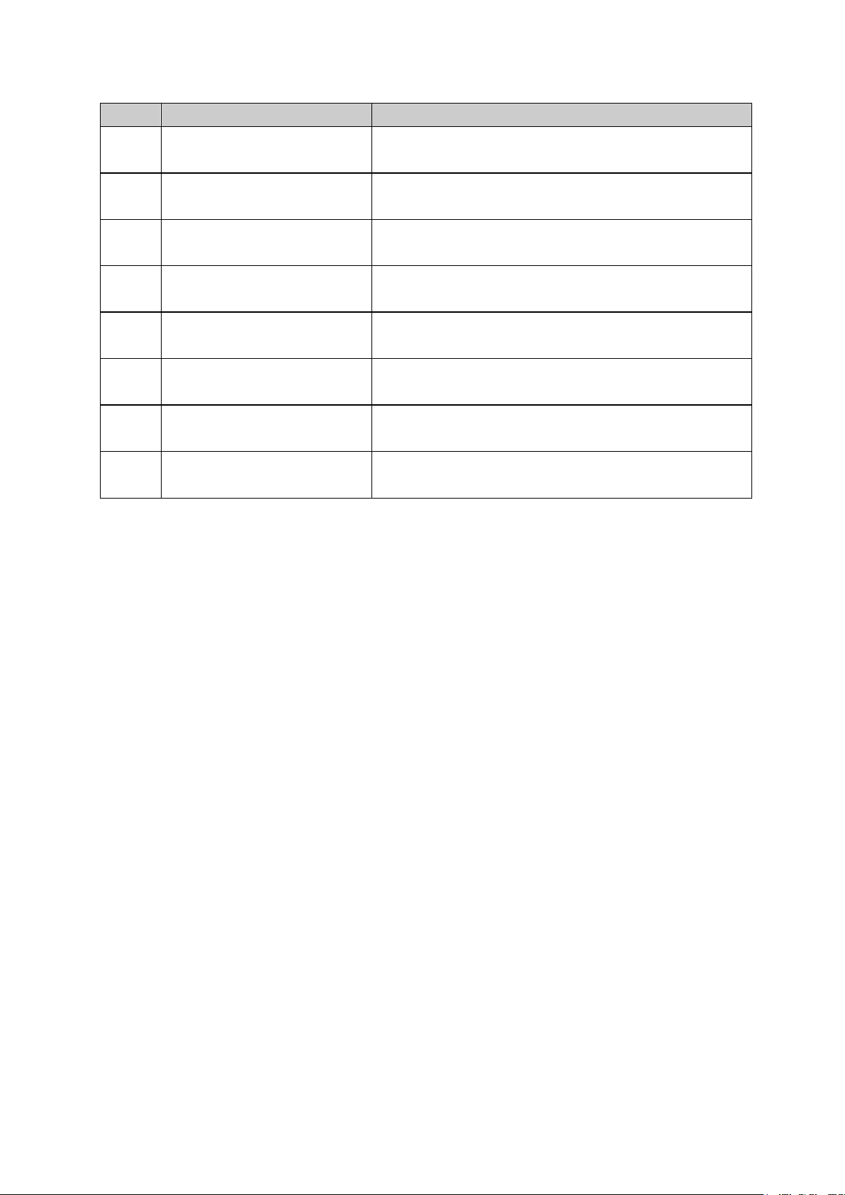
No.
Item
Explanation
for details.)
screen. (See P55 for det ails.)
details.)
P25 for details.)
(See P53 for details. )
P57 for details.)
P58 for details.)
details.)
Menu Items
1 Set Analog Scale Transfers to Analog Scale Selecti on s cr een. (See P55
2 Set Exposure Compensation Transfers to Calibration Compensation Value Setting
3 Custom Setting Transfers t o Custom Setting screen. (See P56 for
4 Set Profile Transfers t o Exposure Profile Selection screen. (See
5 Check/Editing Profile Transfers t o Exposure Profile Edit Selection screen.
6 Edit Frame Rate Transfers to Frame rate Edit Selection scr een. (See
7 Edit Shutter Angle Transfers t o Shut t er Angle Edit Selection screen. (See
8 Edit Filter Transfers t o Fi lt er Edit Selection screen. (See P59 f or
25
Page 26
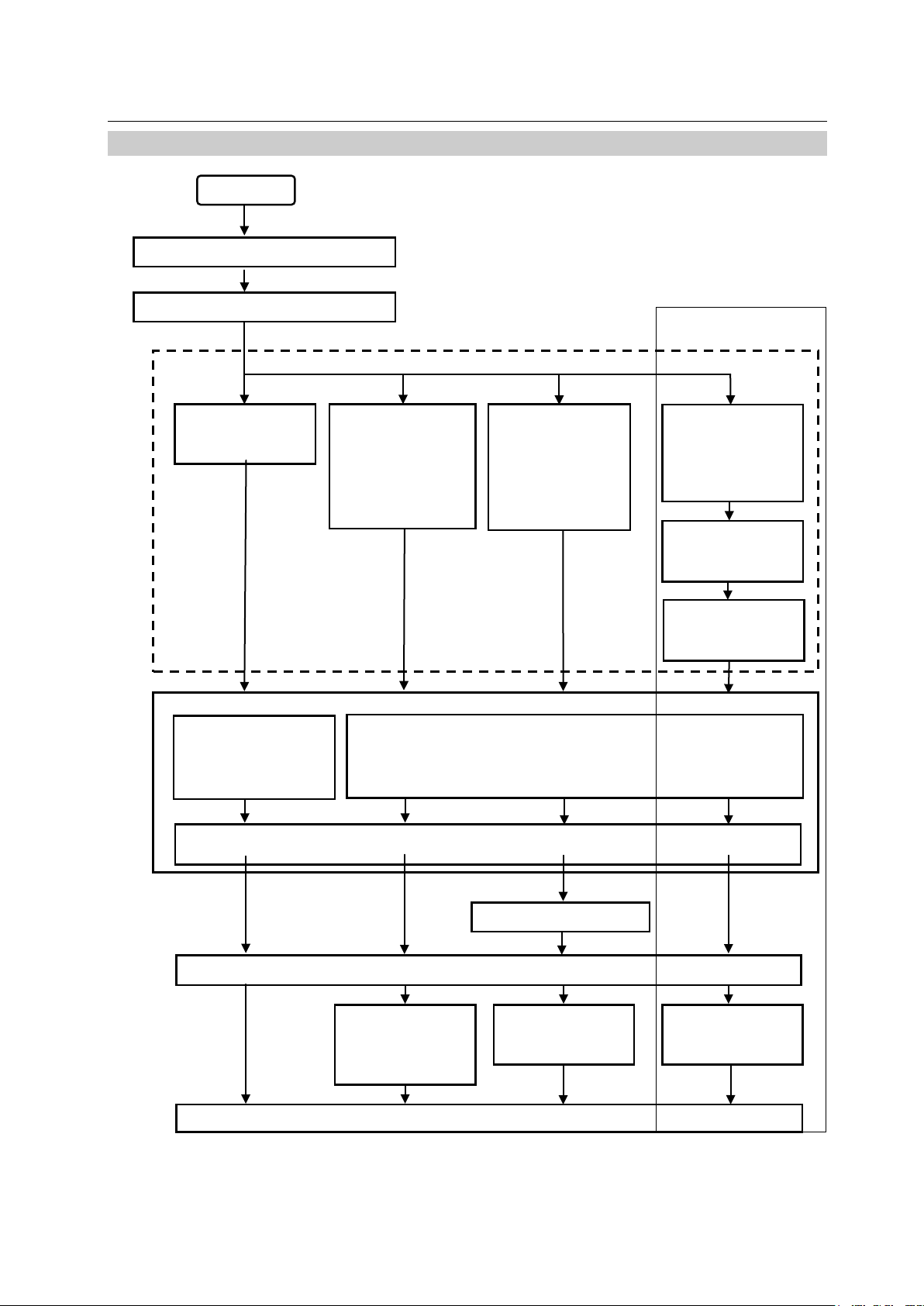
4. Basic Operations
Channel (Zone)
selection (See
Setting Measuring mode (See P25)
Select camera exposure profile
Power ON
Fixed Light mode
within 90
Flash triggers
ISO value, Shutter
See P23 for details.)
(See P25 for details.)
Cord Flash mode
34 for
Cord Flash
(See P38 for
Cordless Flash
(See P38 for
Flash Radio mode
Flash Radio
Adjustment screen
For L-478DR only
4-1 Basic Operation Flow
Set light receiving mode
(See P27 for
details.)
Speed, f-stop, Frame
rate/Shutter Angle
Calibration Compensation amount (See P19 for display and P55 for setting), Filter Compensation
mode (See P35 for
details.)
Cordless Flash
Accumulative mode
details.)
(
(See P
details.)
Accumulative mode
details.)
ISO value, Shutter Speed
(See P51 for details.)
Cord (sold separately)
Measuring (Measuring button ⑧)
L-478D/L-478DR
(See P39)
Accumulative mode
(See P24 )
P38)
Intensity
(See P38)
Manually trigger
flash
seconds
Display of measuring value
26
automatically
Flash triggers
automatically
Page 27
4-2 Setting Light Receiving S ystem
Lumisphere Extended
Lumisphere Retracted (flat)
details).
Ring mark
Extended
Retracted
Lumisphere
② Lumisphere
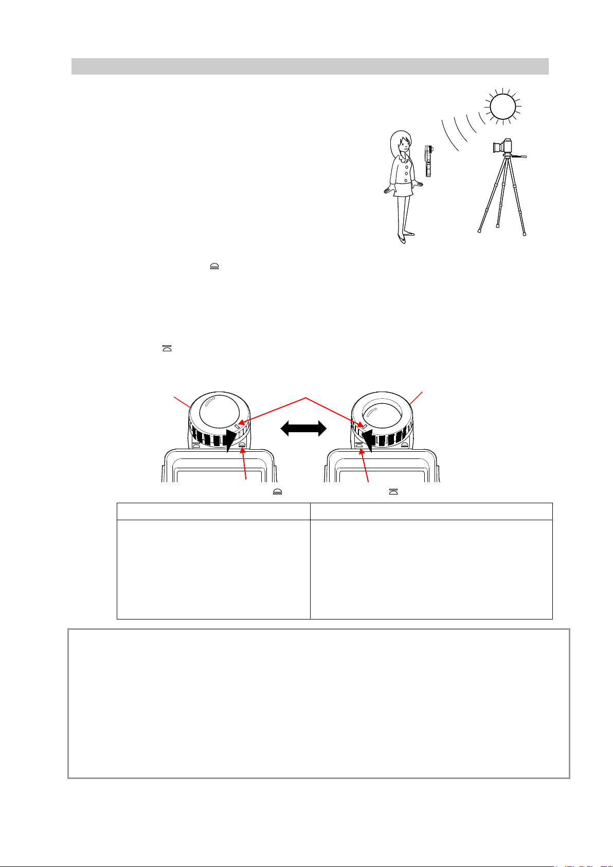
4-2-1 Measuring with Incident Light Function (Lumisphere/Flat)
Use either extended or retr act ed ( flat)
lumisphere to measure incident light. Point
the lumisphere at the camer a ( lens optical
axis) from a position close to the subject and
then measure.
1) Extending Lumisphere
Rotate the upper p ar t of t he lumisphere retracting
ring ② and fully align the ring mark with the
extended symbol (
2) Retracting Lumisphere
Rotate the upper p ar t of t he lumisphere retracting
ring ② and fully align the ring mark with retracted
symbol (
).
).
( )
②
( )
L-478D/L-478DR
Extend lumisphere when measuring
3-D subjects such as pe ople or
buildings.
Retract lumisphere when measuring flat
subjects such as manuscripts, books, pictures,
or when measuring light ing ratio (monitor
function) (see P50 for details) or simply
measuring intensity of ill umination (see P28 for
Caution
● Make sure the measurer does not influence the light measure ment. (Do not block out light
sources. Reflected light occurs due to the color of clothin g. Take care not to let such reflected
light enters Light Recept or Head.)
● If light meter is used with lumisphere retract ing ring set at mid position, luminous intensity
distribution characteri st ics will alter, resulting in inappropriate measuring.
● Do not push down the lumisphere w it h your hand.
● Keep lumisphere and Light Receptor Head clean and free of damage, as failure to do so may
affect accuracy. When lumisphere becomes dirty, wipe clean with a dry, soft cloth. Nev er use
organic solvent (thinner , benzene, etc.).
27
Page 28

L-478D/L-478DR
① Lumisphere lock
Lumispher
マーク
Main unit mark
Light receiving element
4-2-2 Measuring with Reflected Light System
When changing the light r eceiving system to the reflected light
system for use with this main unit, detach the lumispher e,
and attach a viewfind er ( sold separately).
The reflected light system involves measuring the
brightness (luminance) of light reflecting off of the subject.
This method is suited to measuring subjects that cannot
be approached closely, or light emitting subjects (neon
signs, etc.) or light-transm itting subjects (stained glass,
etc.). From the camera position and from the same
direction as the camera, c or rec t ly point t he l ight meter
lens at the part of the subj ect t o be me as ured and take
measurement.
※ See viewfinder manual for details on attaching
viewfinder (sold separately).
1) Detaching Lumisphere
②
Hold down the lumisphere loc k lever ①, take in hand both
the upper and lower rings co mpri s ed in the lumisphere
retracting ring and turn them anticlockwise to detach the
light receding unit.
2) Attaching Lumisphere
Align the mark on the lumisphere r et r acting ring ②
with the mark on the main unit, pr ess the Light
Receptor Head into main unit and then turn to the right
until you hear a clicking sound.
※ Check to see that the lumisphere loc k lev er ① is
sitting up.
Caution
● When attaching/detach ing lumisphere or viewfinder, be sure not to touch the light receiving
element on the main unit side.
28
Page 29

L-478D/L-478DR
Currently
mode
Measuring Mode Selection Screen
To measuring
1
2 3 4 5 6 7 8 9 10
11
12
4-3 Setting Measuring Mode
Touch the meas ur ing mode icon ( ) at the top left of the Measuring screen
and then select any one of the measuring modes.
※ The measuring modes displayed on the M easuring Mode Selection screen w ill change
depending on the settings at Custom Setting. (See P56 for details.)
selected
measuring
screens
29
Page 30

About Measuring Modes
Mode
No.
Icon
Explanation
Fixed Light mode
Fixed light T (shutter speed) priority
and ISO film speed. (See P27 for details.)
Fixed light F (stop) priority
and ISO film speed. (See P28 for details.)
Fixed light TF (expo sur e value [EV]) priority
shutter speed and f-stop. (See P28 for det ai ls.)
Fixed Light Cine
Measures f-stop in accord ance with set shutter
(See P30 for details. )
Fixed Light HD Cine
Measures f-stop in accord ance with set shutter
details.)
Fixed Light mode
Fixed illuminance lux inde pendent display
Measures brightness in lux unit. (See P29 for details.)
Fixed illuminance fc indep endent display
details.)
Fixed luminance cd/㎡ independent display (reflected
details.)
Fixed luminance fl independent display (reflected light
Measures brightness in fl unit. (See P30 for details.)
Cordless flash mode
Cordless flash
details.)
Select cordless flash accumulative measuring screen.
details.)
Cord flash mode
Cord flash (connected)
connected by synchro cor d. ( See P34 for details.)
Cord flash accumulative (connected)
details.)
Flash radio mode
Flash radio mode
a radio receiver. (See P39 for details.)
Flash radio accumulative mode
details.)
L-478D/L-478DR
mode
mode
①
②
③
④
⑤
⑥
Measures f-stop in accord ance with set shutter speed
Measures shutter speed i n acc ordance with f-stop
Measures ISO film speed in acc or dance with set
speed, ISO film speed and shutter opening angle.
speed, ISO film speed and frame rate. (See P30 for
Measures brightness us ing fc value. (See P29 for
light system)
Measures brightness in cd/㎡ unit. (See P30 for
(for L-478DR only)
⑦
⑧
⑨
⑩
⑪
system)
Measures f-stop in accordance with set shutt er speed
and ISO film speed even though the main unit and
flash are not connected (cor dless). (See P35 for
Accumulatively measures f-stop in accordance with
shutter speed and ISO film sp eed even though the
main unit and flash are not connect ed. (See P38 for
Measures f-stop in accord ance with set shutter speed
and ISO film speed with main unit and flash
Accumulatively measures f-stop in accordance with
set shutter speed and ISO film s peed with main unit
and flash connected by synchr o cord. (See P38 for
Measures f-stop in accord ance with set shutter speed
and ISO film speed when the fl ash i s equipped with
⑫
Accumulatively measures f-stop in accordance with
set shutter speed and ISO film s peed when the flash
is equipped with a radio re ceiver. ( See P 42 f or
30
Page 31

L-478D/L-478DR
Reference
● Fixed light r efers t o natural light (sunlight) as well as continuous light like tungsten lamps
and fluorescent lamps.
● Flash re fers t o momentary light such as that produced by a flashlight or flash bulb.
● If all light measuring modes are turned OF F, Fix ed Light T priority will be selected.
31
Page 32

L-478D/L-478DR
Setting value
Measuring value
5. Measuring
5-1 Measuring with Fixed Light Mode
Continuous light like natural light (sunlight) as well as tungst en l amps and fluorescent lamps
are measured in Fixed Light M ode.
The following are the meas ur in g methods in the Fixed Light Mode.
・T (shutter speed) priority
・F (stop) priority
・TF (EV) priority
・ Illuminance lux independent display
・Illuminance fc independent display
・Luminance cd/㎡ independent display (reflected light system)
・Luminance fl independent display (reflected light s yst em)
See 4-3 “Setting Measuri ng Mode” (P25) for details on changing measur ing mode.
Reference
● Shutter speed step numbers are switched using the Custom Setting Funct ion to change in
stepped increments of 1/3 step, 1/2 step or 1 step from the set number 1 [disp layed step].
(See P56 for details.)
● After measuring, if a setting values are changed at setting icons of screens, a measuring
value that corresponds to t hat c hange will be displayed.
● Press (touch) the Average icon (
the Average Function. (Se e P71 for details.)
● The display contents of Analog Scale (m easuring scale and EV scale) w il l change in
accordance with the settings for Measuring mode, Incident/Ref lected and Mid. Tone. (See
P25 for details.)
● See P42 for details about being over or under the display range and measuring range, and
combat these out-of-range issues by eit her c hanging the f-stop or adjustin g t he br ightness
of the measurement light source.
5-1-1 T (Shutter Speed) Priority Measuring
1) Touch the M easuring mode icon at the t op of the
Measuring screen and the n t ouc h t he
appears on the Measuring mod e scr een. (See P25 for
details.)
2) Set the ISO value at the ISO setting.
3) Set the shutter speed at the T icon.
4) Press the Measuring button ⑧ on the main unit.
When the Measuring button ⑧ is released,
measuring will end, and the measuring value (f-stop)
will be displayed.
Continuous measurin g w il l t ake p lac e while the
Measuring button ⑧ is held down.
) at the bottom of the Measuring screen to switch to
icon that
(f-stop)
32
Page 33

L-478D/L-478DR
Setting
Measuring value
Measuring value (shutter speed
Measuring value (EV)
Measuring value (f-stop)
5-1-2 F (f-stop) Priority Measuring
1)Touch the Measuring mode icon at the top left of the
Measuring screen and the n t ouc h t he
icon that
appears on the Measuring mod e scr een. (See P25 for
details.)
2) Set the ISO value at the ISO setting.
3) Set the shutter speed at the F icon.
4) Press the Measuring button ⑧ on the main unit.
When the Measuring button ⑧ is released, measuring
will end, and the measuring value (f-stop) will be displayed.
Continuous measurin g w il l t ake p lac e while the Measuring
button ⑧ is held down.
(shutter speed)
value
5-1-3 TF Priority Measuring
This setting can be used when set at the Custom Setting Function. To select TF Priority, select
item number 0 (ON) for se t t ing number 8 (TF Priority) in Custom Setting Function mode. (See
P56 for details.)
1) Touch the Measuring mode icon at t he top left of
the Measuring screen and then t ouch the
icon that appears on the Measuring mode screen.
(See P25 for details. )
2) Set shutter speed at T icon.
3) Set f-stop at F icon.
4) Press Measuring button ⑧ on main unit
When the Measuring button ⑧ is released,
measuring will end, and ISO fil m speed at that
point will be displayed as the measuring value.
Continuous measurin g w il l t ake p lac e while the
Measuring button ⑧ is held down.
5) Intensity can be addition al ly displayed on the Measuring screen.
Select item number 0 (O N ) for setting number 19 (Luminanc e/Illuminance Independent Display
mode) in Custom Setting Function mode. (See P56 for detai ls. )
5-1-4 Illuminance/Luminance Measuring
Illuminance can be meas ured using the incident light sy s t em and lu m inance can be measured
using the reflected light sys t em. The following are the units that can be set.
See respective unit pa ges for details on operating.
Incident light system (illuminance measuring)
・Lux (Unit: lx)
・Foot candle (Unit: fc)
33
Page 34

Reflected light system (luminance measuring)
・Candela per square meter (Unit: cd/m2)
・Foot-lambert (Unit: fl)
Reference
Calibration compensat ion value will be void with illuminance measuring.
L-478D/L-478DR
34
Page 35

② Lumisphere retracting ring
Measuring screen (lx)
Measuring value (illuminance lx)
Measuring value (illumination fc)
(1) Fixed Light Illuminance lux Independent Display
1) Rotate the lumisphere retracting ring ② and align the ring mark
with the
symbol.
2)Touch the Measuring mode icon at the top left of the Measuring screen
and then touch the icon displayed on the Measuring Mode
Selection screen. (See P25 for details.)
3)Align the surface to be measured with the Light Receptor Head so that
they are parallel and then press the Measuring button ⑧ on the main
unit.
When the Measuring button ⑧ is released, measuring will end, and
illuminance at that point will be displayed as a lux value.
Continuous measuring will be in place while the Measuring button ⑧ is
held down.
(2) Fixed Light Illuminance fc Independent Display
1) Rotate the lumisphere retracting ring ② and align the ring
mark with the
symbol.
2) Touch the Measuring mod e icon at the top left of the
Measuring screen and the n t ouc h t he
icon
displayed on the Measuri ng Mode Selection screen. (See
P25 for details.)
3) Align the surface to be measured with the Light Receptor Head
so that they are parallel and then press the Measuring button
⑧ on the main unit.
When the Measuring button ⑧ is released, measuring will end,
and illuminance at that point will be displayed as an fc (foot
candle) value.
Continuous measuring will be in place while the Measuring
button ⑧ is held down.
L-478D/L-478DR
Measuring screen (fc)
35
Page 36

L-478D/L-478DR
Measuring value (luminance cd/㎡)
Measuring value (luminance fl)
Measuring screen (fl)
(3) Fixed Light cd/㎡ Independent Display (Reflected Light System)
1) Attach a v iewfinder (sold separately). (See P24 for details.)
2) Touch the Measuring mod e icon at the top left of the
Measuring screen and the n t ouc h t he
icon
displayed on the Measuri ng Mode Selection screen. (See
P25 for details.)
3) Look through the viewfinder, and when the desired
measuring area is in the ci rc led s ight, press the Measuring
button ⑧ on the main unit.
When the Measuring button ⑧ is released, measuring w il l
end, and illuminance at t hat point w i ll b e displayed as a cd/㎡
value.
Continuous measurin g w il l be in place while the Measuring
button ⑧ is held down.
(4) Fixed Light fl Independent Di splay (Reflected Light System)
Measuring screen (cd/m2)]
1) Attach a v iewfinder (sold separately). (See P24 for details.)
2) Touch the Measuring mod e icon at the top left of the
Measuring screen and the n t ouc h t he
icon
displayed on the Measuri ng Mode Selection screen. (See
P25 for details.)
3) Look through the viewfinder, and when the desired
measuring area is in the ci r cled s ight, press the Measuring
button ⑧ on the main unit.
When the Measuring button ⑧ is released, measuring w il l
end, and illuminance at t hat point w i ll b e displayed as an fl
value.
Continuous measurin g w il l be in place while the Measuring
button ⑧ is held down.
36
Page 37

L-478D/L-478DR
Measuring value (illuminance)
Setting value
Measuring value (f-stop)
Measuring screen cine camera
5-1-5 Measuring when Shooting with Cine or HD Cine Camera
(1) Measuring when Shooting with Cine Camera
1) Touch the Measuring mod e icon at the top left of
the Measuring screen and t hen t ouc h t he
icon displayed on the Measuring Mode Selection
screen. (See P25 for det ails.)
2) Set frame rate for cine camera at f/s setting icon.
3)
Press the ISO (ISO value) setting icon to display an
expanded view. Set the ISO value in this expanded state.
The normal size will be restored after a set amount of time.
4) Set shutter op en angle at the ANG setting icon.
Press the ANG setting icon to display an expanded view.
Set the ISO value in this expanded state. The normal size
will be restored after a set amount of time.
5) Set the amount of c alibration compensation in
accordance with shootin g par ameters (highlight,
shadow criteria).
6) Press the Measuring button ⑧ on the main unit.
When the Measuring button ⑧ is released,
measuring will end, and the Measuring value
(f-stop) at that point will be displayed.
Continuous measurin g w il l be in place while the
Measuring button ⑧ is he ld down.
Reference
● The f-stop display steps a re s w itc hed using the Custom Setting Function to ch ange in
stepped increments of 1/3 step, 1/2 step or 1 step from the set number 1 [displayed step].
(See P56 for details.)
● There are 20 types of frame rate that can be set at User Settings. (See P57 for details.)
● There are 20 types of shut ter opening angles that can be set at User Settings. (See
P58for details.)
● After measuring, if frame rate is changed at f/s (frame rate) setting icon, an f-stop that
corresponds to that chang e will be displayed.
● After measuring, if ISO value is changed at ISO setting icon, an f-stop that corresponds
to that change will be display ed.
● After measuring, if an gl e is changed at ANG (shutter opening angle) setting icon, an
f-stop that corresponds to that change will be displayed.
● Press the Average icon (
) at the bottom of the Measuri ng scr een to switch to the
Average Function. (See P71 for details.)
● The display contents of Analog Scale (measuring scale and EV scale) will change in
accordance with the settings for Measuring mode, Incident/Ref lected and Mid Tone. (See
P25 for details.)
● See P42 for details abo ut bei ng over or under the display range and measuring range,
and combat these out-of-range issues by either changing the f-stop or adjusting the
brightness.
37
Page 38

L-478D/L-478DR
Setting value
Measuring Screen (HD Cine Camera)
(2) Measuring when Shooting with HD Cine Camer a
1) Touch the Measuring mod e icon at the top left of
the Measuring screen and t hen t ouc h t he
icon displayed on the Measuring Mode Selection
screen. (See P25 for det ails.)
2) Set frame rate for cine camera at f/s setting icon.
Press the ISO (ISO value) setting icon to display an
expanded view. Set the ISO value in this expanded state.
The normal size will be restored after a set amount of time.
3) Set the HD cine camera frame rate at the f/s
setting icon.
Press the f/s setting icon to display an expanded view. Set
the frame rate in this expanded state. The normal size will
be restored after a set amount of time.
4) Set shutter spe ed at the T (shutter speed) setting
icon.
5) Set the amount of calibr at ion compensation in
accordance with shootin g par ameters (highlight,
shadow criteria).
6) Press the Measuring button ⑧ on the main unit.
When the Measuring button ⑧ is released,
measuring will end, and the Measuring value
(f-stop) at that point will be displayed.
Continuous measurin g w il l be in place while the
Measuring button ⑧ is he ld down.
Reference
● The f-stop display steps a re s w itc hed using the Custom Setting Function to ch ange in
stepped increments of 1/3 step, 1/2 step or 1 step from the set nu mb er 1 [displayed step].
(See P56 for details.)
● There are 20 types of frame rate that can be set at User Settings. (See P57 for details.)
● After measur ing, i f speed is changed at T (shutter s peed) s et t ing icon, an f-stop that
corresponds to that chang e will be displayed.
● After measuring, if frame rate is changed at f/s (frame rate) setting icon, an f-stop that
corresponds to that chang e will be displayed.
38
Page 39

L-478D/L-478DR
● After measuring, if ISO value is changed at ISO setting icon, an f-stop that corresponds
to that change will be display ed.
● Press the Average icon (
) at the bottom of the Measuring screen to switch to the
Average Function. (See P71 for details.)
● The display contents of Analog Scale (measuring scale and EV scale) will change in
accordance with the settings for Measuring mode, Incident/Ref lected and Mid Tone. (See
P25 for details.)
● See P42 for details abo ut bei ng over or under the display range and measuring range,
and combat these out-of-range issues by either changi ng t he f-stop or adjusting the
brightness.
39
Page 40

L-478D/L-478DR
Measuring Example in Cord Flash Mode
Measuring value (f-stop)
Component
Setting value
Measuring Example in Cordless Flash
5-2 Measuring in Flash Mode
Measuring in Flash Mode r efers to a measuring method that uses momentary light such as
that produced by a flashlight or flash bulb. The follow ing ar e t he measuring methods used i n
Measuring in Flash Mode.
・Cord Flash Mode (conne ct ed)
・Cordless Flash Mode
・Cord Flash Accumulative Mode
・Cordless Flash Accumulativ e M ode
・Flash Radio Mode (for L-478DR only)
・Flash Radio Accumulative Mode (for L-478DR only)
※The following items exp lain Flash Radio Mode and Flas h Radio Acc umulative Mode.
Also see 4-3 Setting Measuring Mode (P25) for deta i ls on changing measuring mode.
1) About Screen Display Details
When flash light is measured, f-stop (a mixed valu e of
fixed light and flash light = t otal intensity) is displayed
on screen. Also, flash component r at io is d is played in
numerical 10% increments against the total intensity.
The respective measur ing r esults of fixed light (orange)
and flash light (blue) are disp layed in the Analog Scale.
2) About the Analog Scale
Ratio display
Touch the sca le to turn the component ratio display ON or OFF.
3) Light Analyzing Function
With a single measurement the ratio of flash light and fixe d
light are displayed. If flash light is measured, the measuring
value will denote the tot al intensity (a mixed value of flash
light and fixed light). Li kew ise, t he component ratio display
numerically shows in increments of 10% the ratio of flash
light against the tota l intensity. This numeric value can be
used to calibrate shooting to suit the artistic intention – for
example, when shooting w it h a flash in a room lit by tungsten
lamps, the tungsten lamp light (fixed light) can be
strengthened or weaken ed (flash effect strengt hened).
Mode
40
Page 41

L-478D/L-478DR
⑬ Synchro terminal
Setting values
Measuring value (f-stop)
Example of Measuring in Cord Flash Mode
Component ratio display
<Example>
As in the screen on the right, if shutt er speed is 125 and
ISO is 400, the flash compone nt and t ungsten lamp light
will be 50% each. Likewis e, t he respective measuring
results in the Analog Scale for f lash light (blue) and fixed
light (orange) will denote t his.
Reference
● The shutter speed display steps are switched us ing the Custom Setting Function to chan ge
in stepped increments o f 1/3 st ep, 1/2 step or 1 step from the set number 1 [ displayed step].
(See P56 for details.)
● The shutter speeds that can be set will vary depending on the displayed step.
● After measur ing, i f setting values are changed at IS O setting icon, an f-stop that
corresponds to that chang e will be displayed.
● See 8. Setting Range for details on values that can be set for ISO.
● After measur ing, i f speed is changed at T (shutter speed) setting icon, an f-stop that
corresponds to that chang e will be displayed.
● See P42 for details about being over or under the display range and measuring range,
and combat these out-of-r ange issues by either changing t he f-st op or adjusting the
brightness.
5-2-1 Measuring in Cord Flash Mode
In this measuring mode, a synchro cord (sold separately) is used to connect the flash and main u nit.
This is used when full confor m it y with the flash is desired or when mea sur i ng while a flash bulb is
being used.
1) Connect the flash’s synchro cord (sold separately) to
the main unit’s synch terminal ⑬.
2) Touch the M easuring mode icon in the top left of
the screen and then touch the
Measuring Mode Selecti on screen. (See P25 for details.)
3) Set the ISO value at the ISO setting icon.
4) Set shutter speed at the T (shutter speed) i con.
※ Check in advance the confor m ity range of
equipment to be used and t hen m ake
settings.
5) Press the Measurin g but t on ⑧ on the main unit.
The flash will trigger, and the measur ing value
taken at that point will be dis play ed.
icon displayed on the
41
Page 42

L-478D/L-478DR
Caution
● Depending on the flash, it may tr igger when the synch cord is inserted into the synchro
terminal or when the Pow er but t on ⑩ on the main unit is pressed.
● The flash may not trigger w hen it s t r igger voltage is extremely low, et c. I n s uch cases, take
measurement as shown i n 5-2-2 Measuring in Cordless F lash Mode. (See P35 for details. )
● When triggering a flash bulb to make a measurement, check the con formity range and set the
shutter speed.
● When triggering a flash bulb to make a measurement, note that a new bulb has to be loaded
for each trigger of the flash.
● The EV scale cannot be displ ayed.
42
Page 43

L-478D/L-478DR
Setting
Example of Measuring in Cordless Flash
Measuring value
Component
5-2-2 Measuring in Cordless Flash Mode
With this measuring mode, the main unit is set to
measuring standby status (90 seconds), an d dur i ng
this time the flash is triggered and t he measurement
taken. In general, this mode is used when there is
some distance between the flash and the main unit
(the synchro cord will not reach) or t he desire is to
measure the flash without the use of a synchro cord.
1) Touch the Mea s uring mode icon in the top left of
the screen and then touch the
displayed on the Measuri ng Mode Selection
screen. (See P25 for det ails.)
2)Set the ISO value at the ISO set t ing ic on.
3)Set shutter speed at the T (shut t er s peed) icon.
※ Check in advance the conformity range of
equipment to be used and t hen m ake
settings.
4) Press the Measurin g but t on ⑧ on the main unit.
Measuring standby w ill bec ome effective with the
Measuring mode icon
blinking for 90
seconds.
5) The flash has to be triggered manually while the
Measuring mode icon
is blinking.
The measurement will be per f ormed and the
measuring value (f-stop) displayed.
※ If the
icon stops blinking before t he f lash has been
triggered, and you want to st ar t again, pl ease repeat
procedures 4) and 5).
6) To release (cancel) the m easuring standby
status while the icon
is blinking for 90
seconds, touch the screen, or press either the
Memory button ⑤ or Menu button ⑦.
icon
Mode
ratio display
(f-stop
Caution
● If the amount of flash light seems sma ll in comparison to ambient light when flash is triggered,
there are times when the light may not be detected. In such cases, see 5-2-1 Measuring in
Cord Flash Mode (P34) for details on how to measure.
● Under rapid-start fluorescent lamps or special lighting equipment, on rare occasions such
lighting will be judged as flash light, and measured as such. I n suc h cases, see 5-2-1
Measuring in Cord Flash Mode (P34) for details on how to me asur e.
● Even if the flash is not triggered durin g measuring standby status, a sudden change of light in
the Light Receptor Head may cause a measurement to be take n. To avoid this, see 5-2-1
Measuring in Cord Flash Mode (P34) for details on how to me asur e.
● As the triggered light waveform of a flash bulb is gentle, light wil l not be detected in cordless
mode. Therefore, be sure t o see 5-2-1 Measuring in Cord Fl ash M ode (P34) for details on
how to measure.
43
Page 44

L-478D/L-478DR
Synchro terminal
Measuring value (f-stop)
Setting values
Component
5-2-3 Measuring in Cord Flash Accumulative Mode
With this measuring mode, when a single triggering provides an insufficient intensity, multi flash
triggering is performed and the measured value (f-st op) t hat is di splayed matches the value for
accumulative intensity.
The accumulative count w ill be displayed in the Test/Title field.
1) Connect the flash’s synchro cord (sold separately) to
the synchro terminal ⑬ of the main unit.
2) Touch the Measuring mode icon at t he t op left of
the Measuring screen and t hen t ouc h t he
⑬
icon at the displayed Mea sur ing Mode Selection
screen. (See P25 for details.)
3) Set ISO value at ISO setting icon.
4) Set shutter speed at T (shutter speed) setting
icon.
※ Check in advance the confor m ity range of
equipment to be used and t hen m ake settings.
5) Press the Measuring button ⑧ on the main unit.
ratio display
The flash will trigger and the m easuring value
(f-stop) at that point will be displayed.
6) Re peat t his operation (pressing the Mea sur i ng
button ⑧ on the main unit) only for the number of
times necessary.
The flash will trigger and the m easuring value
(f-stop) at that point will be display ed together with
the accumulative count.
Caution
● Depending on the flash, it may tr igger when the syncrho cord is inser t ed into the synchro
terminal or when the Pow er but t on ⑩ on the main unit is pressed.
● The flash may not trigger when its t r ig ger voltage is extremely low, etc. I n suc h cases, take
measurement as shown i n 5-2-2 Measuring in Cordless F lash Mode. (See P35 for details. )
● When triggering a flash bulb to make a measurement, check the con formity range and set the
shutter speed.
● When triggering a flash bulb to make a measurement, note that a new bulb has to be loaded
for each trigger of the flash.
● The EV scale cannot be displ ayed.
44
Page 45

L-478D/L-478DR
Setting values
Example of Measuring with Cordless Flash Mode
Component ratio display
Measuring value (f-stop)
5-2-4 Measuring in Cordless Flash Accumulative Mode
With this m easuring mode, when a single triggering provides an insufficient intensity, multi
flash triggering is perfor m ed and t he measured value (f-stop) that is displayed matches the
value for accumulative intensity.
With this measuring mode, the main unit is set to
measuring standby status (90 seconds) by press ing the
Measuring button ⑧ on the main unit, and during this
standby time the fla sh i s triggered and the measureme nt
taken. A measuring value (f-stop) is displayed for each
trigger of the flash.
The accumulative count is displayed in the Status/T itle
field.
This type of measuring can be used when the
Accumulative mode is ON at t he Cust om Setting
Function. (See P56 for details.)
1) Touch the Measuring mode icon at the top left of
the Measuring screen and then t ouch the
the displayed Measuring M ode Selection screen. (See
P25 for details.)
2) Set the ISO value at the ISO setting icon.
3) Set the shutter speed at the T (shutter speed)
setting icon.
※ Check in advance the confor m ity range of
equipment to be used and t hen m ake
settings.
4) If necessary, set calibration value for
compensation.
5) Press the Measuring button ⑧ on the main unit.
Measuring standby w ill bec ome effective with the
Measuring mode icon (
)blinking for 90
seconds.
6) The flash has to be triggered manually while the
Measuring mode icon
is blinking.
The measurement will be per f ormed and the
measuring value (f-stop) displayed.
※ If the
icon stops blinking before t he f las h has been
triggered, and you want to st ar t again, pl ease repeat
procedures 5) and 6).
7) Repeat this operation (pressing the Measuring button
⑧ on the main unit) only for t he number of times
necessary.
The flash will trigger and the m easuring value (f-stop) at
that point will be displayed together will the accumulat iv e
count.
8) To release (cancel) the measuring sta ndby status
while the icon
is blinking for 90 seconds,
touch the screen, or press either t he M emory
button ⑤ or Menu button ⑦.
icon at
45
Page 46

L-478D/L-478DR
5-3 Measuring with Radio-c ont rolled Flash (for L-478DR only)
5-3-1 How to Measure Using Radio Control
The measuring method using radio control involves connecting a radio receiver ( sold
separately) to the flas h i n or der t o t r igger the flash from the main unit side. This enables one
person to be able to measure the flash without the use of a synchro cor d.
The following are the modes t hat can be set to measure this way.
・ Radio Flash Mode
・Radio Flash Accumulative Mode
Note that prior to measuri ng t he R adio Control channels must be set. ( See P51 for details.)
※ Radio receivers compatible with L-478DR: PocketWizard
manufacturers that equ ip flashes with PocketWizard systems.
Please read the manual p r ovided with the radio receiver for details about operating the
radio receiver.
For compatible products, please se e the LPA we bsite (www.pocketwizard.com).
Caution
● The controllable distance of flash-compatible r adio systems varies in accorda nce with the
position and direction that the radio receiver is set. To set t he best parameters, be sure to
set up the main unit and the radio receiver in the following way.
1. Make sure the main unit and radio receiv er ar e visible to each other in a straight line.
2. Set up the radio receiver away from lar ge metallic objects, concrete or objects containing
a lot of moisture (people or wood, etc.).
3. Use Velcro tape or the tripod sl ot to secure the radio receiver. At this time, make sure the
radio receiver’s antenna is fully above the power source box of the flash. In all situations, do not
allow the radio receiver’s antenna to come into contact with metallic objects.
4. Depending on the location, there ar e cases w hen the radio receiver absolutely cannot
receive a signal. The causes are varied and include radio waves being reflected off of
nearby objects. Normally, this can be rectified by changing the direction of the radio
receiver by several centimeters. Alternatively, check to see if the radio receiver is behind
an object that absorbs or blocks radio waves, such as concr et e, metal or low hill.
5. Under the above parameters, use r adio control at a distance within 30 m et er s.
5-3-2 How to Measure with Radio Control Channels
(1) How to Set a Radio Contr ol C hannel for Use
®
series or other flash
The radio channels that can be used for measuring on this product are Standard Channels and
Control TL Channels.
Control TL Channel:
Among the PocketWizard
(calibrate intensity).
It has 20 channels. Each chan nel has three zones (A, B, C), which me ans t hat up to three
flashes can be controlled by setting a zone.
®
products, this is a radio system that can control power
46
Page 47

L-478D/L-478DR
Stan dard Ch ann els:
®
Among PocketWizard
products, this is a radio system that only triggers fl ashes.
It has 32 channels. Channels No. 1 to 16 are single channels. And, channels No. 17 to 32
are multi channels. Each channel has four zones (A, B, C, D) that can be set, which
means that up to four flashes c an be controlled by one channe l.
47
Page 48

Radio Trigger Channel Setting Screen
Zones
Channel numbers
Radio Trigger Channel Setting Screen
Channel numbers
Zones
Toolbox Screen
(1)-1 Setting Control TL Channel
L-478D/L-478DR
1) Touch the toolbox icon
at the bottom of the
Measuring screen to disp l ay the Toolbox screen and
then touch the RFCh/Zone t ab t o display the Radio
Trigger Setting screen. (See P20 for details.)
2) Touch the CTL tab.
3) Either touch the arrows ▲/▼ or slide the channel
number dial to select a channel from 1 to 20.
4) Set one or more control zones (A to C) for the
channel.
(When Control TL Chann el is set )
5) Touch the OK tab to confirm settings and t hen r et ur n
to the Measuring screen. (Touch the Cance l tab to cancel
settings.)
(1)-2 Setting Standard Channel
1) Touch the toolbox icon
at the bottom of the
Measuring screen to disp l ay the Toolbox screen and
then touch the RF Ch/Zone t ab to display the Radio
Trigger Channel Setting screen. (See P20 for
details.)
2) Touch the STD tab.
3) Either touch the arrows ▲/▼ or slide the channel
(When Standard Channel is set)
number dial to select channel number from 1 to 32.
4) Set control zones for selected channel number.
No settings for channels 1 t o 16
A, B, C, D types for channels 17 t o 32
5) Touch the OK tab to c onfirm settings and return to the[OK]
Measuring screen. (Touch Cancel tab to cancel setti ngs.)
Reference
● When setting both Stan dard Channel and Control T L Ch annel, after both channels and
zones have been selected , set t ing w il l be co m plete once the OK tab is presse d ( t ouched).
48
Page 49

5-3-3 How to Adjust Flash Intensity using Radio Control Screen
Setting
Measuring Screen (Radio
Control Screen
Standard 1~16 Channels
Radio Control Screen
Standar d 17~32 Channels
② ① ③
④ ⑤ ⑥
⑧
Control TL channel &
Compon
ent ratio
display
Standard channel & zone
display
Measuring value (f-stop)
This type of measuring can be used when Radio Trigger
mode is set at the Custom Set t ing Function. (See P73 for
details.)
1) Touch the Measuring mod e icon at the top left of the
Measuring screen and the n t ouc h t he
icon on the
displayed Measuring Mode Selection screen to call up
the Radio Flash mode. (S ee P25 for details.)
2) Touch the Radio Control icon(
) to display the
Radio Control screen.
3) Set flash intensity output at the Radio Control scre en.
※ Please set the channel number t o be us ed in
advance. (See P38 for details.)
1. Touch the Zone buttons you want to selec t.
When using a ControlTL channel: A to C buttons ②
are set at bottom.
2. The plus/minus (+/-) of the bar graph for the selected
zones will become active and the current setting
values will be shown at the t op ③ and in the bar
graph ④.
3. Either touch the +/- symbols on the bar grap h or
slide the bar up/down to set values.
4. Repeat the above items 1 to 3 in order to set t he
remaining desired zones.
5. Pressing the Measuring butt on ⑧ will display in item ⑤
the F value (f-stop) for ea ch zone as calculated out by the set T
value and ISO value.
6. The average F value (f-stop) for all zones will be
displayed in item ⑥.
7. Touch item ⑦ to set ON or OFF modeling lamp
used in measuring.
8. Touch item ⑧ to return to the original Measuring
screen.
4) Check that channel numbers (zones) ar e same for
zone display
the main unit and radio receiver.
Trigger mode)
Control TL +
L-478D/L-478DR
value
⑦
Control TL +
②
49
Page 50

L-478D/L-478DR
Setting value
Control TL channel &
zone display
Component
Standard channel &
Measuring
Caution
●The controllable distance of flash-compatible radio systems varies in accordance with the
position and direction that the radio receiver is set. To set t he best parameters, be sure to
set up the main unit and the radi o rec eiver carefully.
Reference
● The shutter speed display steps are switched us ing the Custom Setting Function to chan ge
in stepped increments of 1/3 step, 1/2 step or 1 step from the set number 1 (displayed step).
(See P56 for details.)
● The shutter speeds that can be set will vary depending on the displayed step.
● After measur ing, i f setting values are changed at IS O setting icon, an f-stop that
corresponds to that chang e will be displayed.
● See 8. Setting Range for details on values that can be set for I SO .
● After measur ing, i f shutter speed is changed at T (shutter s peed) setting icon, an f-stop that
corresponds to that chang e will be displayed.
● See P42 for details about being over or under the display range and measuring range, and
combat these out-of-range issues by either changing the f-stop or adjusting the brightness.
5-3-4 Measuring in Radio Flash Mode
This type of measuring can be used if Radio Trigger mode
settings have been made at t he Cust om Setting Function.
(See P73 for details. )
1) Touch the Measuring mode icon in the top left of the
Measuring screen and the n t ouc h t he
displayed Measuring Mode Selection screen. (See P25 for
details.)
2) Set the ISO value at the ISO setting icon.
3) Set the shutter speed at the T (shutter speed)
setting icon.
※ Check in advance the confor m ity range of
equipment to be used and t hen m ake
settings.
4) When you want t o c alibrate flash intensity, touc h t he
Radio Control icon
to display the Radio Control s cr een
and then set flash intensit y output.
6) Check that channel numbers (zones) are sa me for
the main unit and radio receiver.
7) Press the Measuring button ⑧ on the main unit.
The flash will trigger and the m easuring value (f-stop) at t hat point w il l
be displayed.
icon in the
zone display
ratio display
value (f-stop)
50
Page 51

L-478D/L-478DR
Control TL
channel & zone
display
Component
Standard channel &
Measuring
Example of Over Exposure Display
Example of Under Exposure Display
Setting
value
Measuring
Screen
5-3-5 Measuring in Radio Flash Accumulative Mode
This type of measuring can be used if Radio T r igger mode
settings have been made at t he Cust om Setting Function.
(See P73 for details. )
1)Touch the Me as uring mode icon in the top left o f t he
Measuring screen and the n t ouc h t he
icon in the
displayed Measuring Mode Selection screen. (See P25
for details.)
2) Set the ISO value at the ISO setting icon.
3) Set the shutter speed at the T (shutter speed) set t ing
icon.
※ Check in advance the confor m ity range of
equipment to be used and t hen m ake settings.
4) Set calibration v alue for amount of compensation if
necessary.
zone display
5) When you want to calibrate flash intensity, touch the
Radio Control icon
to display the Radio Control
screen and then set flash i nt ensity output.
7) Check that channel numbers (zones) are sa me for t he
main unit and radio receiv er.
8) Repeat the operation of pressing the Measuring b utton
⑧ on the main unit) only for t he number of times
necessary.
The flash will trigger and the meas ur ing value (f-stop)
at that point will be display ed t ogether with the
accumulative count in the bot t om title field.
5-4 What to do when Displayed Range or Meas uring Range is Exceeded
(※This example explains what needs to be done in Cord Flash mode.)
5-4-1 When Displayed Range is Exceeded
Even within the measuring r ange of this product, the “Over” (over exposure) me ssage will be
displayed for the maximum f-stop (F128) and t he “Under” (under exposed) me ssage will be
displayed for the minimum f-stop (F0.5) in the s et shutter speed. In such cases , t ake the
following action.
(1) When over exposure “Over” is displayed:
・ When the display range is exceeded and t he “Over” message appears, change the
ratio display
value (f-stop)
51
Page 52

L-478D/L-478DR
When brightness exceeds measuring
When brightness is under the measuring range
shutter speed to a higher speed at the T (shutter speed) icon. A suitable f-stop in
accordance with the new set t ing w i ll b e displayed.
(2) When under exposure “Under” is displayed:
・ Also, when the display range is exceeded and the “Under” message appears, chang e the
shutter speed to a lower speed at the T (shutter speed) icon. A suitable f-stop in
accordance with the new set t ing w i ll b e displayed.
5-4-2 When Displayed Range is Exceeded
When brightness (or darkness) exceeds the measur ing range of this product, the “Over” (or
“Under”) message will blink to inform the user that measuring is not possible. In such cases,
adjust the brightness.
52
Page 53

L-478D/L-478DR
Setting value
Measuring value (f-stop)
Memorized measuring value s (f-stop)
6. Functions
6-1 Memory Function
This product can memorize measur in g values. This function can be used with Fixed Light
Shutter S peed Priority, F (f-stop) Priority, EV Priority and Flash (cord connected, cordless)
modes. Regardless of whether the system is incident or r efle ct ed l ight, up to nine
measurement values can be m emorized and displayed. For example, after a value is
memorized in incident lig ht settings, it will remain in memor y even if settings are switched to
reflected light, and a memor y value for the new reflected light sett in gs can be displayed.
6-1-1 Memory
1) Press the M eas uring button ⑧ on the main unit
when at the Measuring screen.
2) Press the Memory button ⑤ to memorize measuring
value.
The memorized measur ing value will be displayed as
a dot on the scale.
3) Items 1) and 2) can be repeated.
Up to nine measuring values can be memorized.
Caution
● Memory Function cannot be used with the following flash accumulative modes.
・ Cord Flash Accumulative Mode
・ Cordless Flash Accumulative Mode
・ Radio Flash Accumulative Mode (for L-478DR only)
● The tenth measurement v alue onw ard will be displayed but will not be memorized.
Measuring Screen
53
Page 54

6-1-2 Memory Recall
Toolbox
Memory Recall Selection
Memory Recall Screen
This function is used to recal l memorized contents for
viewing. Memory recall it ems are listed in order, with
memory contents (memory number, incident light
reflected light
In Analog Scale, memorized measuring values are
displayed as dots on t he scale.
1) Touc h the Toolbox icon
Measuring screen.
2) Touch the Memory Recall tab on the Toolbox scr een.
(See P20 for details. )
3) The Memory Recall Selection screen will be
displayed and the memory contents will be shown.
Touch a desired item to view its deta ils .
4) The detailed contents will be displ ayed in the
Memory Recall screen.
For Analog Scale, the recalled measuring value will
be displayed.
5) Touch the Close tab to return to the Measuring screen.
Touch the Me mory Recall tab to return to the Memory
Recall Sele c tion screen.
6) Touch the Close tab at the Memory Recall Selection
screen to return to the Measuring screen.
and measuring value) disp layed.
at the bottom of the
or
Caution
● Memory cannot be recalled if there are no memorized memory values.
L-478D/L-478DR
Screen
54
Page 55

Toolbox Screen
Memory Clear Screen
6-1-3 Memory Clear
Memorized measuring values ca n be cl ear ed
individually or collectively.
Memory recall items are li st ed in order, with memory
contents (memory number, incident light
light
Recall screen.
In Anal og Scale, memorized measur i ng values are
displayed as dots on t he scale.
1) Touc h the Toolbox icon (
2) Touch the Memory Clear tab in the display ed Toolbox
screen. (See P20 for det ails.)
3) Touch the items you want to clear from the Memory
Clear screen. The Clear Confirmation screen will ap pear, so
select either the OK or Cancel tab. Pressing the OK tab
clears the item, and then the show n contents will be
redisplayed minus the cleared item.
4) Repeat items 2) and 3) above to clear other memory
5) Touch the Close tab at the M em or y Clear screen to
T otal Memory Clear:
Touch the ALL tab in procedure item 3) above. The Clear
Confirmation screen wi ll a ppear, so touc h t he OK tab to clear
all items and return to the Toolbox scree n.
and measuring value) display ed in the Memory
)at the bottom of the
Measuring screen.
items as necessary.
return to the Toolbox screen.
or reflected
Caution
● Memory Clear cannot be selected if ther e are no memorized memory values.
L-478D/L-478DR
55
Page 56

L-478D/L-478DR
Mid. Tone Set Screen
Mid. Tone Set Screen
Mid. Tone Set
6-2 Mid. Tone Function
Mid. Tone is a function used to set the middle tone as the standard when the camera exposure
profile function is to be used.
Mid. Tone has the following four functions.
・Sets measuring value as mid tone.
・Selects memorized measuring values (maximum of
nine) and sets as mid tones.
・Corrects mid tones.
・Recalls mid tone s
6-2-1 Setting Measuring Value as Mid. Tone
1) Press the Measuring button ⑧ of the main unit
whilst in any Measuring mode.
2) Touc h the Toolbox icon
Measuring screen.
3) Touch the Mid. Tone Set tab in the displayed Toolbox
screen. (See P20 for det ails.)
4) Touch the Set from Current Measurement tab in the
displayed Mid. Tone Set screen to set the current meas uring
value as a mid tone.
5) Touch the Close tab in the Mid. Tone Set screen to
return to the Toolbox screen.
6-2-2 Setting Memorized Measuring Value as Mid. Tone
1) Touc h the Toolbox icon at the bottom of the
Measuring screen.
2) Touch the Mid. Tone Set tab in the displayed Toolbox
screen. (See P20 for det ails.)
3) Touch the Set from Memory tab in the displayed Mid.
Tone Set screen.
The Mid. Tone Memory Set Screen will appear, with memor y
contents (memory number, incident light
light
In Anal og Scale, memorized measur i ng values are displayed
as dots on the scale.
4) Touch the Measuring value you want t o set as a mid
tone. The touched Me as uring value will be set and the
Measuring screen will be restored. At t his t i m e, the newly set
mid tone will be displayed on t he Analog Sc ale.
and measuring value) display ed.
5) Touch the Close tab on the Mid. Tone Memor y Set
screen to return to the Measuring screen.
at the bottom of the
or reflected
(Memory) Screen
56
Page 57

Displayed settings
during measuring
Mid. Tone Modification
Displays measuring result
Mid. Tone Set Screen
Toolbox Screen
Caution
● This cannot be set if there are no memoriz ed m emory values.
6-2-3 Mid. Tone Modification
This enables minute adju stment of the currently set Mid.
Tone value.
1) Touc h the Toolbox icon
Measuring screen.
2) Touch the Mid. Tone Set tab in the displayed Toolbox
screen. (See P20 for det ails.)
3) Touch the Modify Current Mid. Tone tab in the
displayed Mid. Tone Set screen.
The Mid. Tone Modification screen will be displayed.
4) Either touch the arrows ▲/▼ or slide the number
dial to modify the value.
5) Touch the OK tab to c onfirm modification and return to the
Measuring screen. Touch the Cancel tab to return to the
Measuring screen without making the modification.
at the bottom of the
Caution
● Modification is not possible if there are no mid t one settings.
6-2-4 Mid. Tone Clearing
This clears the set mid tone.
1) Touc h the Toolbox icon
Measuring screen.
2) Touch the Mid. Tone Clear tab in the displayed
Toolbox screen. (See P20 for details. )
The current mid tone setti ng cont ents will be cleared
and the Measuring screen r estored.
3) Touch the Cancel tab to ret ur n t o t he M easur ing screen
without clearing contents.
at the bottom of the
Caution
● Clearing is not possible if t her e ar e no mid tone settings.
L-478D/L-478DR
57
Page 58

Toolbox Screen
Mid. Tone Recall Screen
6-2-5 Mid. Tone Recall
This is a function for recal l ing t he set mid tone for viewing.
1) Touc h the Toolbox icon
at the bottom of the
Measuring screen.
2) Touch the Mid. Tone Recall tab in the displayed
Toolbox screen. (See P20 for details. )
3) The current mid tone setting contents in the
Measuring screen will be displayed.
4) Touch the Close tab in the Mid. Tone Recall screen to
return to the Measuring screen.
Caution
● Recalling is not possible if there are no mid tone sett ings.
L-478D/L-478DR
58
Page 59

L-478D/L-478DR
Averaged values
Exposure Metering Screen
Setting
Measuring value
Memorized measuring values (f-stop)
Exposure Metering
6-3 Average Function
The Average Function can average out up to nine memorized readings and display the average.
This function can be used w ith the following modes: Fixed Light Shutter Speed priority, f-stop
priority and Flash (cord, cordless, radio trigger).
1) Press the Measuring button ⑧ on the main unit.
2) Press Memory button ⑤ to memorize Measuring
value.
The memorized measur ing value will be displayed as
a dot in the scale.
3) Repeat items 1) and 2).
Up to nine measuring values can be memorized.
4) Touch the Average tab(
screen.
The average value for all the memory will be
displayed. And the Ave mark will be disp layed in the
screen. When the Average Function is running, the
Average icon
will be displayed in the negativ e
. .
5) To r emove average, touch the Average icon
The Ave mark will disappear from the middle of the
screen.
)at the bottom of the
.
59
Page 60

L-478D/L-478DR
② Lumisphere
EV Difference of Measuring
Value
Illumination Ratio
1
2:1
1.5
3:1
2
4:1
3
8:1
4
16:1
Exposure Metering Screen
6-4 Monitor Function
This is a useful function for checking studio lighting and illuminati on irregularities.
After setting as the standard a measuring value at some point and th en holding down the
Measuring button ⑧ at a location you want to comp ar e w it h, t he difference between t he
standard value and the other location will be disp layed as an EV value (step number) in t he
measuring value display fi eld. I n t he Analog Scale, the current measuring value will be
displayed.
※ The standard value will use the last measuring value w hen there are no measuring values
in memory. When there are me asuring values in memory, it will use the average value of all the
memory.
Example of illumination ratio measuring using the Monitor Function (i n Shutter Speed
Priority Mode with incident light system):
When measuring illumin ation ratio of the main light source a nd fill light source, use the Flat
Function (lumisphere ret r acted) to measure.
1) Rotate the Lumisphere retr acting ring ② until fully
switching to the flat position.
2) Turn ON just the main light source.
Place the Light Receptor Head close t o t he subject
and point it toward the main light source.
3) Touch the Average tab( )at the bottom of the
screen.
the Ave mark will appear on screen, and the main
light source value will bec om e t he standard value.
When the Average Function is running, the Average
icon
will be displayed in the negative
. .
4) Next, turn ON just the fill light source.
Now, point the lumisphere at t he fill l ight source, hold
down the Measuring button ⑧, and the difference
between measuring values for main and fill light
sources will be displayed as an EV value.
Simultaneously, the memory value and monitor value
(compared location mea suring values) will be
displayed on the Analog Scal e, enabling you to get
an illumination ratio (cont r ast ratio).
60
Page 61

L-478D/L-478DR
Touch
AVE
after
memorizing
Setting value
Screen Example (Main Light
Setting
Screen Example (Fill Light
Source Measuring)
Source Measuring)
/⊿EV
5) To remove Monitor, touch the Average icon
middle of the screen.
. The Ave mark will disappear from the
Reference
● The exposure decider when measuring in incident light inv olves turning ON both the
main and fill light sources, set t ing t he Light Receptor Head to lu m isphere extended,
pointing it at the camera (lens optical axis) and then measurin g.
● The Monitor Function also c an be used when measuring with re fl ect ed light.
61
Page 62

L-478D/L-478DR
Filter Number and Compensation Value
Filter Compensation Setting
Screen
Current filter
compensatio
Toolbox Screen
6-5 Filter Compensation Functi on
By registering and setting the filter compensation value in the light m et er, measuring result s
that reflect the compensation value can be obtained.
This is a useful function for mea sur i ng exposure when a filter is be ing used on the camera lens.
Again, when deciding exposure using the highlight standard or shutter standard, having each of the
compensation values registered in advance is useful.
The setting range of the filter com pensation value is ±5.0EV.
The following are the thre e types of filter compensation that c an be selected.
1) Filter co mp ensation value setting (Input n umeric value. The
the top of the screen.)
2) Selection of a filter name that has be en r egistered in advance
(Up to four filter names can be set , and the
icon will be displayed at the top of the
screen.)
3) Filter compensation cancel (The
icon will disappear from the top of the screen.)
6-5-1 Setting Filter Numbers and Compensation Values
These can be set in steps of 0.1 EV at a range of ±5.0EV.
1) Touc h the Toolbox icon (
screen.
2) Touch the Filter Comp. tab in the displayed Toolbox
screen. (See P20 for det ails.)
3) Touch the radio button for Input Filter Comp. Value in
the displayed Filter Co mp ensation Setting screen.
4) Input the compensation value in the display ed Filter
Numbers and Compensation Value Setting screen and then
touch the Enter tab. (See P22 for details about inputting.)
The original screen will be restored and the input
compensation value displayed.
5) Touch the OK tab to return to t he M easuring screen.
)at the bottom of the
icon will be displayed at
Setting Screen
62
Page 63

Reference
● Plus compensation will cause over exposure in shooting and minus co mpe nsation will
cause under exposure.
L-478D/L-478DR
63
Page 64

L-478D/L-478DR
Filter Compensation
Setting Screen
Filter Compensation Setting
Filter
names
Toolbox Screen
Filter Compensation List
6-5-2 Selecting Filter
(1) Setting Amount of Filter Compensat ion
1) Touc h the Toolbox icon
at the bottom of the
Measuring screen.
2) Touch the Filter Comp tab in the dis pl ayed Toolbox
screen. (See P20 for det ails.)
3) Touch-select the radio button for Select Fi lter factor
number in the displayed Filter Compensation Setting screen.
4) Touch the filter name you want to set in the list in the
middle of the screen.
5) In the displayed Filter Selection screen, either touch
or slide with your fingers the arr ows ▲/▼ to display the
desired number and then touch it to select it.
6) Repeat items 4) and 5) to set up to four
compensation values as n eces sary. (All of the set
compensation values wi ll become compensation
objectives.) After selecting the necessary filter names,
touch the Close tab to return to the Filter
Compensation List screen.
5) Having r et ur ned t o the Filter Compensation List
screen, please check that sel ect ed f ilter names are
displayed.
Touch the Clos e tab to return to the Filter
Compensation Setting screen.
6) To end operation, touch the OK tab at the Filter
Compensation Setting screen, to return to the
Measuring screen.
Reference
● See 8. Registered Filters for details about preset filters at time of sh ipping from factory. (See
P65 for details.)
● The user can set filter c om pensation values. (See P59 for det ails.)
6-5-3 Deselecting Filter
1) Touc h the Toolbox icon at the bottom of the
Measuring screen.
2) Touch the Filter Comp tab in the dis pl ayed Toolbox
screen. (See P20 for det ails.)
3) Touch-select the radio button for N o Filter in the
64
Page 65

displayed Filter Compensation Sett ing scree n.
Icon
Exposure Profile Information
Screen
ISO Selection Screen
Exposure Profile Editing
Selection Screen
4) Touch the OK tab to return to the Measuring screen.
6-6 Functions by Menu Selection
6-6-1 Exposure Profile Selection/Editing Function
With Data Transfer Softw are created exposure profiles , if
you want to edit (numeric values, names) using the
L-478D/L-478DR, this is the function to use. Also, you can create
exposure profiles indep endently with the L-478D/L-478DR.
(The maximum number of exposure profiles that can be
created are ten profiles.)
(1) Camera Exposure Profile Selection
1) Press the Menu button ⑦ on the main unit. (See P21 for
details.)
2) Touch 4. Set Profile in displayed Menu screen.
3) Items selected (check marked) ☑ are shown in the
displayed Exposure Profile Editing Selection screen.
To change profiles, either touch or slide your finger
over the arrows ▲/▼ to display a desired exposure
profile name and then tou ch it to select it.
4) When the exposure pr ofile name is touched, the
Measuring screen will be restored.
(2) Exposure Profile Editing
L-478D/L-478DR
1) Press the Menu button ⑦ on the main unit.
(See P21 for details.)
2) Touch 5. Check/Edit Profile on the displayed Menu
screen.
3) In the displayed Exposure Profile Edit Select ion
screen, either touch or slide w ith your fingers the
arrows ▲/▼ to display the desired exposure profile
name and then touch it to select it.
Items selected (chec k marked) ☑ are shown.
4) In the display ed Exposure Profile Informat io n sc reen,
touch one of the icons denotin g an exposure metering mode.
※ Selectable icons will be highlighted.
5) At the display ed I SO Selection screen, touch the
arrows ▲/▼ to display the desired ISO exposure profile
information and then touch it to select. The display can be
changed by sliding your fi nger up and down over the exposure
profile information.
6) Edit characteristics at the displayed Camera
65
Page 66

Film Speed Characteristic Setting screen.
Tolerance range
[
]
[
-
]
[
]
[ + ]
Camera Film Speed Characteristic Setting Screen
Compensation value cursor
Compensation
value (cursor
and movement)
-
Reproduction field
Tolerance range
+
Reproduction field
Exposure Profile Edit Selection
Screen
ISO Selection Screen
1. Touch the compensatio n v alu e cur s or to set
compensation value.
The cursor can be moved horizontally within the ±
5EV range.
The setting value is numerically displayed above the
cursor.
2. Set tolerance range (-), reproduction field (-),
reproduction field (+) and tolerance range (+) of the various
cursors.
Settings can be made to fulfill a range with the following
parameters: tolerance range (-) ≦ reproduction field (-)≦
reproduction field (+)≦tolerance range (+).
3. Touch the OK tab to return to the ISO Selection
screen.
(Touch the Cancel tab if editing is not needed.)
L-478D/L-478DR
7) Touch the Close tab at the ISO Selection screen to
return to the Exposure Profile Edit Selection screen.
※ If necessary, modify the current exposure profile
name. (See P55 for details.)
8) Touch the Close tab to return to t he M enu scr een.
Reference
● To return exposure pro fi les to t he initial settings, see the application software guide in
Data Transfer Software (o n t he CD-ROM) for details.
(3) Changing Exposure Profile Name
1) Press the Menu button ⑦ on the main unit. (See
P21for details.)
2) Touch 5. Check/Edit Profile on the displayed Menu
screen.
3) In the displayed Exposure Profile Edit Select ion
screen, either touch or slide w ith your fingers the
arrows ▲/▼ to display the exposure profile name
you want to change and then touc h it t o select it.
66
Page 67

L-478D/L-478DR
Exposure Profile Information Screen
EV scale
Measuring
Analog Scale Selection Screen (for incident light)
Exposure Profile Name Input Screen
Items selected (chec k marked) ☑ are shown.
4) In the displayed Exposure Profil e I nformation screen,
touch the Edit Profile nam e tab.
5) Input a name at the displayed Exposure Profile Name
Input screen and then press Enter. (See P13 for details
on inputting.)
6) Touch the Close tab to return to the Exposure Profile
Edit Selection screen.
6-6-2 Analog Scale Switching
At the bottom of screens, such as the Measuring screen, there is a scale to display readings such as the
latest measuring value, memory value, monitor value, average value, and tolerance range and
reproduction field. This scale can be switched between a measuring value scale and an EV scale.
1) Press the Menu button ⑦ on the main unit. (See P1 for
details.)
2) Touch 1. Set Analog scale in the displayed Menu
screen.
3) At the displayed Analog Scale Selection screen, touch
the Measurement Scale (f-stop standard scale) or the
value scale
EV Scale.
4) Touch the OK tab to return to the Menu screen.
(Touch the Cancel tab if you do not want to make a
selection.)
6-6-3 Calibrated Compensation Value Function
This product is corrected to a standard based on the Sekonic standard, but thi s me asuring
standard can be changed by using the Calibrated Com pensation Function. The compostable
range is ±9.9EV.
When using the Calibrated Compensation Function, first set the measuring mode (incident light or
reflected light). Compensation can be set independently for both incident and reflection.
67
Page 68

L-478D/L-478DR
Setting
Compensation value
for displayed
for displayed
for displayed
Calibration Compensation Value Setting Screen
Conditions for Minus Compensation:
Use minus compensation to prevent over exposure (whiteout, unnaturally bright shots) when
shooting in strong light.
Conditions for Plus Compensation:
Use plus compensation to prevent under exposure (blackout, unnaturally dark shots) when
shooting in weak light or darkness.
1) Confirm that the Measuring mode is selected.
2) Press the Menu button ⑦ on the main unit. (See P21
for details.)
3) Touch 2. Set Exposure Compensation on the displayed
Menu screen.
4) Sett compensation value at Calibration Compensation
Value Setting screen.
The minimum input unit is 0.1 EV. (See P31 for details.)
5) Touch the Enter tab to return to the Menu screen.
Caution
● When compensating, base your com pensations on the results of suffic ie nt test shooting and
your own personal prefer ences.
Reference
● When setting the calibrated compensation value, the icon will be displayed in the
screen title field to show t hat compensation is being perfor m ed.
● The amount of calibrated compensation can be confirmed using the icon at the
Information screen.
● The conventional Sekonic setting metho d inv olves selecting the setting nu mb er 3
(compensation value +/- definition) and item number 1 at the Custom Setting Function.
(See P56 for details.)
The following are possible: plus compensation for under exposure (increase f-stop or shutter
speed [= plus] achieves under exposure) and minus compensation for over exposure
(decrease f-stop or shutter speed [= minus] achieves over exposure).
6-6-4 Custom Setting Function
This enables the setting in advance of necessary functions a nd display methods. (See P57 for
details.)
(1) Custom Setting Function List
Custom Setting Name Item Number
No.
1
2
3
Displayed step
Fraction display
+/- definition
※1
※2
0 1 2 3 Default
1 step 1/3 段 1/2 段 ― 1 step
ON OFF ― ― ON
Increases
(compensation
value)
Decreases
(compensation
― ―
value)
Increases
(compensation
value
68
Page 69

Switching
Left: Memory
Left: Memory
Fixed light
cine camera
Display of additional
independent display
Liquid crystal
Liquid crystal
backlight brownout
Measuring/Memory
4
buttons
※3
L-478D/L-478DR
Left:
button
Right:
Measuring
button
Measuring
button
Right: Memory
button
Auto switching※3 ―
button
Right:
Measuring
button
5
measuring※6
6
T priority mode※6
7
F priority mode※6
8
TF priority mode※6
9
Cine camera mode
HD
10
mode※6
11
Flash measuring※6
12
Cordless mode※6
13
Cord-in mode※6
Radio trigger mode
14
(L-478DR のみ)
受信機タイプ選択
15
(for L-478DR only)
16
Accumulative mode※4
17
measuring data
Illuminance/luminance
18
19
20
unit setting
Illuminance/luminance
mode
Screen color scheme Black White Rose Blue Black
ON OFF ― ― ON
ON OFF ― ― ON
ON OFF ― ― ON
ON OFF ― ― OFF
※6
ON OFF ― ― OFF
ON OFF ― ― OFF
ON OFF ― ― ON
ON OFF ― ― ON
ON OFF ― ― ON
ON OFF ― ― ON
Control TL Standard CH
ON OFF ― ― OFF
None EV value Illuminance/luminance ― None
lux or cd/m2 fc or fl
ON OFF ― ― OFF
ControlTL +
Standard CH
― ―
― Control TL
lux or cd/m2
Auto power off time 5 min 10 min 20 min None 5 min
21
22
brightness
23
time
Custom Setting
24
reset※5
Bright Medium Dark ― Medium
20 sec 40 sec 60 sec
― ― ― ― OK/Cancel
No
brownout
20 sec
※1 Fractions in all modes are displayed in steps of 1/10.
※2 Fraction ON/OFF will be effective on ly when displayed step is 1/3 step or 1/2 s t ep.
※3 Auto switching: Measuring button ⑧ and Memory button ⑤ will be standard
configuration with incident light system, but the button configuration will reverse
automatically with the ref l ec t ed l ight system.
※4 When turned ON, the following can be set in t he M easuring Mode Selection screen:
Cordless Flash Accu mu lative mode, Cord Flash Accumul at ive mode and Radio Flash
Accumulative mode (for L-478DR only).
※5 This returns all items set in Custom Setting to the default s et t i ngs . Touch OK tab to return
default setting and touch Ca ncel tab to cancel the default settings.
※6 When all Measuring modes are turned OFF, the fixed light T Priority mode will be
selected.
69
Page 70

(2) Setting Custom Setting
Custom Setting Screen
Custom Setting Item Changing Screen
Frame rate Input Screen
Frame rate Edit Selection Screen
1) Press the Menu button ⑦ on the main unit. (See
P21 for details.)
2) Touch 3. Custom Setting in the displayed Menu
screen.
3) In the displayed Custom Setting scr een, either touch
or slide with your fingers the arr ows ▲/▼ to display
the desired number and then touch it to select it.
※ See (1) Custom Setting Function List ( P56) f or
details on item number s.
4) Touch-select the desired radio button from the
options in the detailed screen.
The ● symbol denotes the currently selected item.
5) Touch the OK tab to return to the Custo m Set t ing
screen.
(Touch the Ca ncel tab when you do not want t o mo di fy.)
6) Repeat items 3) to 5) above to set other Custom
Setting items.
7) Press the M enu button ⑦ at the Custom Setting
screen to return to the Menu screen.
6-6-5 Frame rate User Setting
In addition to the standard available frame rates, a maximum of 20 frame rates can be
registered.
Registered frame rates can be edited freely.
※ Frame rate is set in units of 0.001(f/s) over a range of
0.001 to 9999.999(f/s).
1) Press the Menu button ⑦ on the main unit. (See
P21 for details.)
2) Touch 6. Edit Frame Rate in the displayed Menu
screen.
3) The previously set frame rate items ar e check
marked (☑) in the displayed Fra me rate Edit
Selection screen.
4) In the displayed Frame rate Edit Selection screen,
either touch or slide with your fingers the arrows ▲/
▼ to display the desired frame rate and the n t ouch it
to select it. Items selected (check marked) ☑ are
shown.
5) Input the numerical value in the display ed Frame
rate Input screen and then touch the OK tab. (See
P13 for details on inputting.)
After the OK tab is tou c hed, the Frame rate Edit
Selection screen will be restored.
L-478D/L-478DR
70
Page 71

L-478D/L-478DR
Shutter Opening Angle Edit Selection Screen
Shutter Opening Angle Input Screen
6) Press the Menu button ⑦ to return to the Menu
screen.
7) The added frame rate will be added to the tail end of
the selection order at the Exposur e Metering screen.
Reference
● Frame rates without a check mark (☑) will be displayed with two dashes (- -).
6-6-6 Shutter Opening Angle User Setting
In addition to the standard available shutter opening ang les, a maximum of 20 shutter opening
angles can be set. Set shutt er opening angles can be edited freely .
※ Shutter opening angles ar e r egistered in units of 0.001°over a range from 0.001 to
360°.
1) Press the Menu button ⑦ on the main unit. (See
P21 for details.)
2) Touch 7. Edit Shutter Angle in the displayed Menu
screen.
3) The previously set opening angle items are check
marked (☑) in the displayed Shutter Opening Angle
Edit Selection screen.
4) In the displayed Shutter Opening Angle Edit
Selection screen, either touch or slide with your
fingers the arrows ▲/▼ to display the desired
shutter opening angle and then touch it to select it.
Items selected (chec k marked) ☑ are shown.
5) Input shutt er opening angle and then touch the Enter
tab. (See P13 for det ails on inputting.)
After the OK tab is touched, t he Shut t er O pening
Angle Edit Selection scre en will be restored.
At the Shutter Opening Angle Edit Sel ect i on s cr een, press
the Menu button ⑦ to return to the Menu screen.
7) The added shutter opening angle will be added t o t he
tail end of the selection order at the Exposure
Metering screen.
Reference
● Frame rates without a check m ark (☑) will be displayed with tw o das hes ( - -) and they will
not have opening angle valu es.
71
Page 72

L-478D/L-478DR
72
Page 73

L-478D/L-478DR
Filter Display Screen
Filter name edit
butt
Filter Compensation Input Screen
Filter Edit Selection Screen
Filter Display Screen
Filter
value button
6-6-7 Filter User Setting
The user can set up to 30 filter comp ensations. Set filter compensat i on contents can be edited
freely.
※ Filter compensation is set in 1/10 steps in a range of ±9.9EV.
※ User-set filter compensations are selected at the time of measuring in the same way as
the filter compensations i ncorporated in the main unit ( s ee P51 for details).
※ See P65 for details on registered filter types.
1) Press the Menu button ⑦ on the main unit. (See P21 for
details.)
2) Touch the 8.Edit Filter at the Menu screen.
3) The previously set filter names are check marked
(☑) in the displayed Filter Edit Selection scre en.
4) Either touch or slide with your fingers the arrows ▲/
▼ to display the desired item an d t hen t ouch it to
select it. Items selected (check marked) ☑ are
shown.
5) Set amount of filter compensation at the displayed
Filter Display screen.
1. Touch Filter Compensation button.
2. Input amount of compensation at d isp layed Filter
Compensation Input screen and then tou c h t he O K
tab. (See P13 for det ails on inputting.)
The input compensation v alue will be displayed at
the Filter Display screen.
6) Change filter names as necessary at the displayed Filter
compensation
Display screen.
1. Touch the Filter name butt on.
2. Input the filter name at the displayed Filt er Na me
Input screen and then touch the OK tab. (See P52
on
for details on inputt ing.)
The input name will be displayed in the Filter
73
Page 74

Display screen.
The Filter Display screen w il l be restored.
L-478D/L-478DR
74
Page 75

L-478D/L-478DR
ISO Selection Screen
Icons
Exposure Profile Information
Screen
Filter Name Input Screen
Exposure Profile Edit Selection
3. Touch the Close tab at the Filter Di splay screen to return to
the Filter Edit Selection sc r een.
4. Press the Menu button ⑦ at the Filter Edit Selection
screen to return to the Menu scr een.
Reference
● Classified filters are preset from 1 to 24. (See P65 for details.)
● The user can set filters from 25 to 30 ( in itia l v alue is : - -).
6-6-8 Exposure Profile Editing Function
(1) Exposure Profile Function
Use this function in cases w her e you want to refer to or edit exposure pro f il es created in the
Data Trans fer Softwar e at the main unit side. Further, you can create exposure profiles
independently with the ma in unit. (The maximum number of e xposure profiles that can be
created is ten.)
(2) Editing Exposure Profile
1) Press the Menu button ⑦ on the main unit. (See P21 for
details.)
2) Touch 5. Check/Edit Profile in the displayed Menu
screen.
3) The previously set exposure profile names ar e check
marked (☑) in the displayed Exposure Profile Edit
Selection screen.
4) Either touch or slide with your fingers the arrows ▲/
▼ to display the desired exposure profile name and
then touch it to select it. It em s selected (check
marked) ☑ are shown.
5) Touch one of the icons denoting a Measuring mode in the
displayed Exposure Profile Infor mation screen.
6) At the displayed ISO Selection screen, touch t he
arrows ▲/▼ to display ISO exposure profile
information that you want to edit and then touch it to
select it. You also can slide your finger up and down
over the exposure profile information to switch
information.
7) Edit characteristics at the displayed Camera F il m Speed Charact er istic Setting Screen.
1. Slide the compensation value cursor left or right
to set compensation value . Li kewi se, you can
press the +/- tabs to set t he compensation value.
75
Page 76

L-478D/L-478DR
Exposure Profile Edit Screen
[カメラ感度特性設定画面]
補正値カーソル
補正値(カーソル
と連動)
再現領域[-]
許容範囲
[-]
再現領域[+]
許容範囲
[-]
The cursor can be moved horizontally within the ±
5EV range.
The setting value is numerically displayed above the
cursor.
2. Set tolerance range (-), reproduction field (-),
reproduction field (+) and tolerance range (+) of the
various cursors.
Settings can be made to fulfill a range with the
following parameters: tolerance range (-) ≦
reproduction field (-)≦reproduction field (+)≦
tolerance range (+).
3. Touch the OK tab to con f irm an d t hen r et ur n to
the Exposure Profile Information screen.
(Touch the Ca ncel tab if you do not want to edit.)
8) Touch the Close tab at the Expos ur e Profile
Information screen to return to the Exposure Profile
Edit Selection screen.
※ Modify current exposure profile names a s
necessary (See below for details.)
9) Press the M enu button ⑦ on the displayed Exposure
Profile Edit Selection scre en t o r et ur n t o the Menu screen.
右上画面の英訳
Camera Film Speed Characteristic Setting Screen
Compensation value cursor
Compensation value (cur sor and movement)
Tolerance range [-]
Reproduction field [+]
Reproduction field [-]
Tolerance range [-]
Reference
● See the Application Software Guide in the Data Tra nsf er Software on the CD-ROM for details
on returning exposure pro fi les to t he initial settings.
(3) Changing Exposure Profile Name
1) Press the Menu button ⑦ on the main unit. (See
2) Touch 5. Check/Edit Profile in the displayed Menu
3) At the displayed Exposure Profile Edit Select ion
P21 for details.)
screen.
screen, touch or slide your fing er up and down over
the arrows ▲/▼ to display the exposure profile
76
Page 77

name that you want to change and then touch it to
Exposure Profile Information Screen
Exposure Profile Name Input Screen
select it.
The selected exposure profile names are check
marked ☑.
4) Touch Edit Profile Name in the dis played Exposure
Profile Information scre en.
5) Obtain a name at the displayed Exposure Pr ofile
Name Input screen and then pr ess Enter. (See P13
for details on inputt ing.)
6) Touch the Close tab to return to the Exposure Profile Edit
Selection screen.
7) Press the Menu button ⑦ at the displayed
Exposure Profile Edit Sel ection screen to return to
the Menu screen.
L-478D/L-478DR
77
Page 78

L-478D/L-478DR
⑩ Power button
⑦ Menu button
User Calibration Screen
Hardware Setting Screen
6-7 Hardware Setting Screen
(1) Hardware Setting Screen
The following settings can be performed at the Hardware Set t ing screen.
・User calibration of EV value
・Adjust touch panel display position
・Returning to default sett i ngs (factory settings)
・Editing user information
1) Hold down the Menu button ⑦ and press the Power
button ⑩ to turn ON the power.
The Hardware Setting screen will be displayed.
2) Touch the desired menu item.
1. User Calibration
Setting in advance means that compensation values
in measuring results can be calibrated using EV
value units.
(Setting range: -1.0EV to 1.0EV)
2. Adjust Touchpanel
The coordinate positions rec ognized by the touch sensor of the
touch panel can be adjusted.
3. Factory Setting
Parameters and setting contents are initialized back to factory
setting.
See Custom Setting (P56) for details on contents of factory settings.
3) When finished, press the Power button ⑩ to turn OFF the
power.
(2)User Calibration Operating Met hod
1) Press the User Calibration ta b at t he Hardware Setting
screen to display the User Cal ibration screen.
2) Using buttons at bottom of screen, adj ust setting value in
increments of ±0.1EV.
3) Press the Close button to retur n t o t he Exposure
Metering screen.
78
Page 79

(3)Adjust Touch Panel Operating Method
T ouch Panel Adjusting
T ouch Panel Adjust
Factory Setting Screen
Factory Setting Confirmation
1) T ouch the Adjust Touch Panel tab as the Hardware
Setting screen to display t he Touch Panel Adjusting
screen.
2) A w hite c ros s mark will light up at the top left of the
screen. Please touch this cr oss . A red cross mark wi ll b e
displayed in the touched position.
3) After touching, a white cr oss mark will appear in another
position every time a red cr os s appears, so repeat this
touch-and-display process eight ti me s.
4) After that, the Touch Panel Adjust Confir mation screen
will be displayed.
Press the OK button when you want to make
adjustments.
To cancel adjustments, press the Canc el b utton.
5) After pressing the OK or Canc el button, setting will be
ended and the Exposure Metering screen restored.
(4)Factory Setting Operating Method
1) Press Factory Setting at the Hardware Set t ing screen to
display the Factory Sett in g Confirm screen.
2) When implementing, if you are not going to implement
the settings with the Yes button, then please press the
No button.
3) Pressing the Yes button displays the Factory Setting
Confirm screen.
4) Pressing the Yes button implements the factory settings.
Pressing the No button m eans t hat the settings will not
be made.
5) After either pressing the OK or C ancel button, setting will
end, and the Exposure Meter ing screen will be restored.
L-478D/L-478DR
79
Page 80

(5)User Information Editing
1) Press User Information Edit at t he Hardware Setting screen to
display the alphabet input scr een. User information can be edited
here.
2) Changed user information wil l be di splayed on the Information
screen. (See P20 for details.)
(Number of alphabet characters that can be input: 31 charact ers)
7. Separately Sold Accessories
・ Synchro Cord
This is a three-way, five-meter long cord that sync
connects light meter, flas h and camera, which is great
because there is no need t o replug cords when shooting.
Also, one of the synchro cord’s connectors has a lo cking
mechanism to prevent disconnection.
(Cord has two male connectors and one female one.)
The connector with the lock function is a male one.
・Standard Gray Card
This is a gray card (110mm x 10 2mm) with 18% reflection
ratio. 1
With this card, you can check the standard measuring value
during shooting.
By using the standard gra y card to determine standard
exposure for results of meas ur i ng, you can acquire the
exposure data that will provide faithful color reproduction.
・Exposure Profil e Targe t
This is the test chart (260m m x 1 60mm) used to create
camera exposure profile s. The front features nine types of
gray patches including bla ck and w hite ones, while the
rear is 18% gray card, so it can be used t o det ermine
white balance for digital cameras and exposure with the
reflected light system.
・Exposure Profil e Targe t Ⅱ
This is the test chart (350m m x 1 20mm) used to create
camera exposure profile s. The front features 25 types of
gray patches including wh ite and black ones, while the
rear is 18% gray card, so it can be used to determine white
balance for digital cameras and exposure with the
L-478D/L-478DR
80
Page 81

reflected light system.
・Viewfinder 5°
This is a viewfinder with a five degree acceptance angle.
When measuring with the r eflect ed light system, remove t he
lumisphere and attach the viewfinder. When a subject
cannot be approached clo sely, point the viewfinder lens
correctly at the part of the subject to be measured and
make the measurement. (See P29 for details.)
L-478D/L-478DR
81
Page 82

L-478D/L-478DR
8. Registered Filters
Registered filters can be displayed at Filter Name Selection. The following are the registered filters
and their compensation values. (See P52 for details.)
No.
Filter Name
Compensation
1
2
3
4
5
6
7
8
9
10
11
12
13
14
15
16
17
18
19
20
21
22
23
24
CTO Double -2.1
CTO Full
CTO Three-Quarter
CTO Half
CTO Quarter
CTO Eighth
No.85
CTB Double
CTB Full
CTB Three-Quarter
CTB Half
CTB Quarter
CTB Eighth
Minusgreen Full
Minusgreen Half
Minusgreen Quarter
Minusgreen Eighth
Plusgreen Full
Plusgreen Half
Plusgreen Quarter
Plusgreen Eighth
ND0.3
ND0.6
ND0.9
-1.1
-0.8
-0.5
-0.3
-0.1
-0.8
-3.3
-1.5
-1.3
-0.9
-0.4
-0.3
-0.9
-0.5
-0.3
-0.2
-0.4
-0.2
-0.1
-0.2
-1.0
-2.0
-3.0
82
Page 83

L-478D/L-478DR
ng function (attachable/detachable viewfinder
uring using radio trigger (with/without accumulative) (for
9. Specifications
Type ●Digital light meter for flash and fixed light
Light Receiving Method ● Incident light and reflected light
Receptor Head ●Incident light Retract (flat) function
(by retracting the lumisphere into the main unit, the flat function
can also be used)
●Reflected light Lumisphere removi
[sold separately])
Light Receptor Element ● Silicon photo diodes
Measuring Modes ●Fixed light f-stop priority measuring
Shutter speed priority measuring
TF priority measuring
Cine camera measuring
HD cine camera measuring
Illuminance measuring (lux, foot candle)
Luminance measuring (foot-lambert, cdm2)
●Flash Measuring using synchro cord (with/without accumulative)
Measuring without synchro cord (with/without accumulative)
Meas
L-478DR only)
Repeat accuracy ●±0.1EV or less
Calibration Constant ●Incident light Lumisphere C = 340, Flat C = 250
●Reflected light K = 12.5
Setting Range ●ISO ISO 3 to 409600 (in 1/3 steps)
●Shutter speed
Fixed light 30 min to 1/64000 sec (in 1, 1/2 and 1/3 steps)
Other possible settings: 1/200, 1/400 sec
Flash light 30 min to 1/1000 sec (in 1, 1/2 and 1/3 steps)
Other possible settings: 1/75, 1/80, 1/90, 1/100, 1/200, 1/400
●f-stop
●Frame rate (f/s)
F0.5 to F128(in 1steps)
1 to 1000, other possible settings: 20 types
●Shutter opening angle
1°to 358°other possible settings: 20 types
●Monitor display -5.0EV to +5.0EV (in 1/10 steps)
●Filter compensation -9.9EV to +9.9EV(in 1/10 steps)
●Filter compensation selection Maximum of 4 types can be used simultaneously
●Accumulative count 0 to 99 times (Maximum of 99 times is displayed)
●Compensation display -9.9EV to +9.9EV (in 1/10 steps)
●Monitor display -9.9EV to +9.9EV (in 1/10 steps)
●Filter compensation -5.0EV to +5.0EV (in 1/10 steps)
83
Page 84

L-478D/L-478DR
ne, manganese,
Soft case, strap, 2 4AAA dry cell batteries,
fications in this manual and external appearance may be subject to
Measuring Range (ISO100)
●Fixed light
FNo.0.5 to FNo.161 (in 1/3 steps)
FNo.0.5 to FNo.128 (in 1steps)
FNo.0.5 to FNo.152 (in 1/2 steps)
Incident light EV-2 (F2.0, 15 sec) to EV22.9 (Approx F22.9, 1/8000
sec)
Reflected light EV2.0 to EV19.9
●Flash light component Incident light F1.0 to F128.9
Reflected light F2.8 to F128.9
●Illuminance 0.631(EV-2.0) to 2,000,000 (EV19.6) lux
0.058 (EV-2.0) to 180,000 (EV19.6) foot candle
●Luminance (Reflected light)
0.5 (EV3) to 980,000 (EV22.9) cdm2
0.10 (EV1.5) to 290,000 (EV22.9) foot-lambert (for L-478DR only)
●EV value EV-27.9 to EV55.8 (only effective with fixed light)
●Analog display T scale 2s to 1/8000
F scale F0.7 to F128(in 1/3 steps),
EV scale
-3EV to +3EV (incident light, in 1/3 steps)
-7EV to +7EV (reflected light, in 1/3 steps)
Illuminance lux
Illuminance fc (foot candle)
0 to 50,000 lux
0~5,000 fc
Luminance cd/㎡ (candela per square meter) 0~2,500 cd/㎡
Luminance fl (foot-lambert) 0~1,000 fl
Other Functions ●Accumulative count 0 to 99 times (Display: Max 99)
●Compensation display -9.9EV to +9.9EV(in 1/10 steps)
●Exposure profile display Max 10 profiles
●Light analyzing function 0 to 100% (in 10% increments)
●Memory function 9 readings
●Memory clear/recall function
●Average function
●Exposure out of range and display Under, Over warning display
●Battery power indicator display 4 stages
●Auto power OFF function Can be selected at Custom Setting
●Liquid crystal backlight (EL) ON (OFF after set time elapses)
●Touch Panel lock function
●Custom setting function 22 items (L-478D), 24 items (L-478DR)
Battery ●Dry cell battery 2 4AAA dry cell batteries (alkali
lithium, nickel hydride, or nickel based)
Operating temperature range ●-10℃ to 50℃ (no condensation)
Storage temperature range ●-20℃ to 60℃ (no condensation)
Dimensions ●Approx 56(W)×136(H)×25(D)mm (excluding protrusions)
Weight ●Approx 160g (L-478D without batteries), 170g (L-478DR without batteries)
Standard accompanying accessories ●
Startup Guide, CD-ROM (Users’ Manual (this manual) and Applications)
For improvement reasons the speci
84
Page 85

L-478D/L-478DR
future changes without prior notification.
10. Usage Precautions
Caution
● To avoid damaging this meter, never drop it or subject it to shock.
● Avoid using it in water spray or rain as doing so may cause damage.
● Avoid storing it in high-temperature and/or humid locations as doing so may cause damage.
● Beware of condensation caused by sudden temperature change, as such condensation may
cause damage or malfunction.
● If the temperature of the meter drops to -10 deg. C or beyond, response of the LCD becomes
extremely slow and displays are difficult to read. At temperatures between 0 and 10 deg. C the
LCD will become somewhat slower than normal but this does not hinder usage. Also, when the
temperature exceeds 50 deg. C, the LCD will turn black and will be hard to read. This will return
to normal when the temperature returns to normal.
● Do not place the meter in direct sunlight during midsummer or near heaters, etc., as the
temperature of the meter will rise beyond that of the air temperature. Be careful when using
the meter in hot locations.
Maintenance Notes
● If your meter is splashed with water, wipe immediately with a soft dry cloth. Leaving the meter
wet may cause rust or corrosion
● Keep the light receptor head away from dust/dirt and avoid scratching as accuracy may be
affected.
● When light meter gets dirty, clean it with soft dry cloth. Never use organic cleaners (like thinner
or benzene).
85
Page 86

L-478D/L-478DR
11. About Aftercare Service
● About Warranty Period
1. The warranty period is on e year from the date of purchase.
2. A war r ant y without the date or retailer’s name w il l be r egar ded as invalid. Always confirm
that the warranty has date and retailer name.
3. Note that in some cases there are paid-for repairs ev en w hile the product is under warranty,
so always confirm the warr ant y conditions.
4. Once the warranty expires, repairs will be charged fo r. Furthermore, costs – such as
shipping - will be the responsibility of the customer.
● About Warranty Period of Repair Parts
1. Repair parts are usually stocked for seven years after product is discontinued. Theref or e,
once this period is exceeded, we may not be able to accept repair work.
2. Repaired products will be issued with a Seko ni c delivery slip, so please confirm this slip.
3. Products that have been submerged in water, subjected t o s t r ong shocks, or markedly
damaged in any other way, and, as such, are deemed difficult to repair successfully, will be
deemed unviable for repair, even if they are still under war r ant y.
● Requesting Repairs
1. For product repair, please inc lude a letter with thorough explanation of the problem,
problem location or servic e t o be per formed. If these are not indicated, a thorough
inspection in terms of qua l ity and performance of the product in ques tion will be required,
and this may increase any charges due regarding rep airs.
2. Among the requests for r epair , w e sometimes find that all that needs to be don e is t he
simple task of replaci ng the batteries. Please thoroughly check that battery pow er and the
loading direction (+/- is correct).
● Inquiries
Please contact the Sekonic Sales Department w ith inquiries about the warranty, repairs and
usage of this product.
This product is guaranteed against irregularities occurring due to defects in m anufacturing;
however, we will not take respo nsi bility for any other irregular ities.
86
Page 87

This equipment has been tested and found to comply with the limits for a Class B digital device, pursuant to part
15 of the FCC Rules. These limits are designed to provide reasonable protection against harmful interference
in a residential installation. This equipment generates, uses and can radiate radio frequency energy and,
if not installed and used in accordance with the instructions, may cause harmful interference to radio
communications. However, there is no guarantee that interference will not occur in a particular installation. If this
equipment does cause harmful interference to radio or television reception, which can be determined by turning
the equipment off and on, the user is encouraged to try to correct the interference by one or more of the
following measures:
- Reorient or relocate the receiving antenna.
- Increase the separation between the equipment and receiver.
- Connect the equipment into an outlet on a circuit different from that to which the receiver is connected.
- Consult the dealer or an experienced radio/TV technician for help.
Caution: Any changes or modifications to this device not explicitly approved by manufacturer could void your
authority to operate this equipment.
)&&:DUQLQJ
This device complies with part 15 of the FCC Rules. Operation is subject to the following two conditions: (1) This
device may not cause harmful interference, and (2) this device must accept any interference received, including
interference that may cause undesired operation.
IC Warning
This device complies with Industry Canada licence-exempt RSS standard(s).
Operation is subject to the following two conditions: (1) this device may not cause interference, and (2) this
device must accept any interference, including interference that may cause undesired operation of the device.
Le présent appareil est conforme aux CNR d'Industrie Canada applicables aux appareils radio
exempts de licence. L'exploitation est autorisée aux deux conditions suivantes : (1) l'appareil ne doit
pas produire de brouillage, et (2) l'utilisateur de l'appareil doit accepter tout brouillage radioélectrique
subi, même si le brouillage est susceptible d'en compromettre le fonctionnement.
 Loading...