

Page 1

PARTS LIST / TECHNICAL GUIDE
KINETIC DIRECT DRIVE Cal. 5D88A
[SPECIFICATIONS]
5D88A
Driving system Step motor 2 pieces
Additional functions
• Direct drive indicator
Power reserve indicator
Real-time power indicator
• Energy depletion forewarning function
• Overcharge prevention function
• Electronic circuit reset function
• Second hand stop function
• Date correction function
• Moon phase display func tion
Crown operation
Normal position
Free
1st click position
Day set ting ( clockwise), Date setting (counterclock wise)
2nd click position
Time setting, hand position adjustment, reset ting the circuit
Loss/gain
Monthly rate: less than 15 seconds
(worn on the wrist at temperature range between 5 to 35 ºC)
Regulation system Nil
Measuring gate by quartz tester
10-second gate
Current consumption
Movement: less than 0.65
μA
Circuit block : nil
Circuit block for calendar: less than 0.40 μA
Coil resistance
4002535 1 piece:1.90K Ω - 2.15KΩ Coil block for hour,minute, and second hand
4002540 1 piece :0.585KΩ - 0.645KΩ Generating coil block
4002529 1 piece:1.25KΩ - 1.50KΩ Power reserve coil block
Power supply
Power generator
Automatic generating system + Manual winding power generating system
Rechargeable
battery
MT920 Manganese titanium lithium rechargeable battery
Operating voltage range
1.05V - 2.50V
Maximum continuous operating time
Approximately 1 month after the watch is fully charged
Number of jewels 12 jewels
• 3 hands (Hour, Minute and Second hands) ,
24-hour hand
• Calendar (Date dial, Day dial, Moon phase)
Cal. No.
Item
Movement
• Casing diameter:
Ø 28.0 mm
• Diameter
Outside: Ø 30.0 mm
Height : 6.52 mm
Page 2
BEFORE STARTING REPAIR WORK ON CAL. 5D88A
2/51
SEIKO Kinetic Direct Drive Cal. 5D88 is an embodiment of the SEIKO’s ‘emotional technology’.
The watch features new functions but the knowledge of repairing the existing KINETIC series
will be helpful.
To repair the Cal. 5D88, therefore, you are requested to have the full knowledge of its functions
and strictly observe the repairing and checking instructions provided in this guide so that the
watch will be correctly repaired.
FEATURES
1. DISPLAY AND HOW TO USE
The Cal. 5D88 is a KINETIC watch equipped with two winding functions and two indicator
functions.
l
Two winding functions
As in all existing Kinetic calibers, the wearer automatically generates the electrical
energy by her/his wrist movement. With Kinetic Direct Drive, however, the wearer can
also generate energy by winding the crown.
l
Tw
o indicator functions
Kinetic Direct Drive shows not only the power held in reserve but also the level of power
generation when the wearer hand-winds the crown. The wearer can see and feel, in real
time, the direct transfer of power from his or her winding of the crown to the reserve.
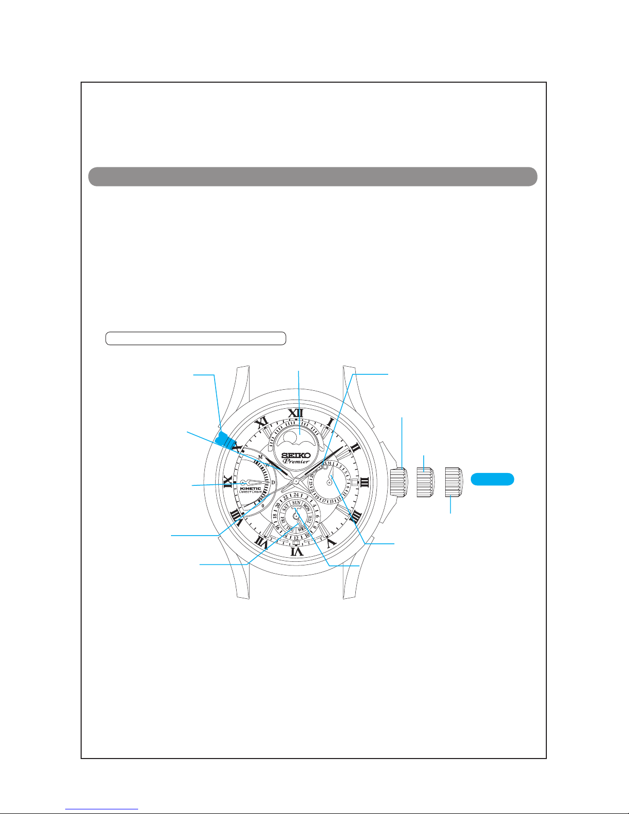
15
10
5
0
02
15
25
29
1
2
2
First click position: Date
and day setting
Second click position:
Time setting
Hour hand
Direct drive indicator
hand (for indicating
amount of power
reserved, power
generation status and
amount of generated
power)
Date hand
Day hand
Minute hand
Normal position: Electric power
generation by manual winding
Second hand
Button (moon phase
setting / resetting the
built-in IC)
CROWN
24-hour hand
Moon phase display
Page 3
BEFORE STARTING REPAIR WORK ON CAL. 5D88A
3/ 51
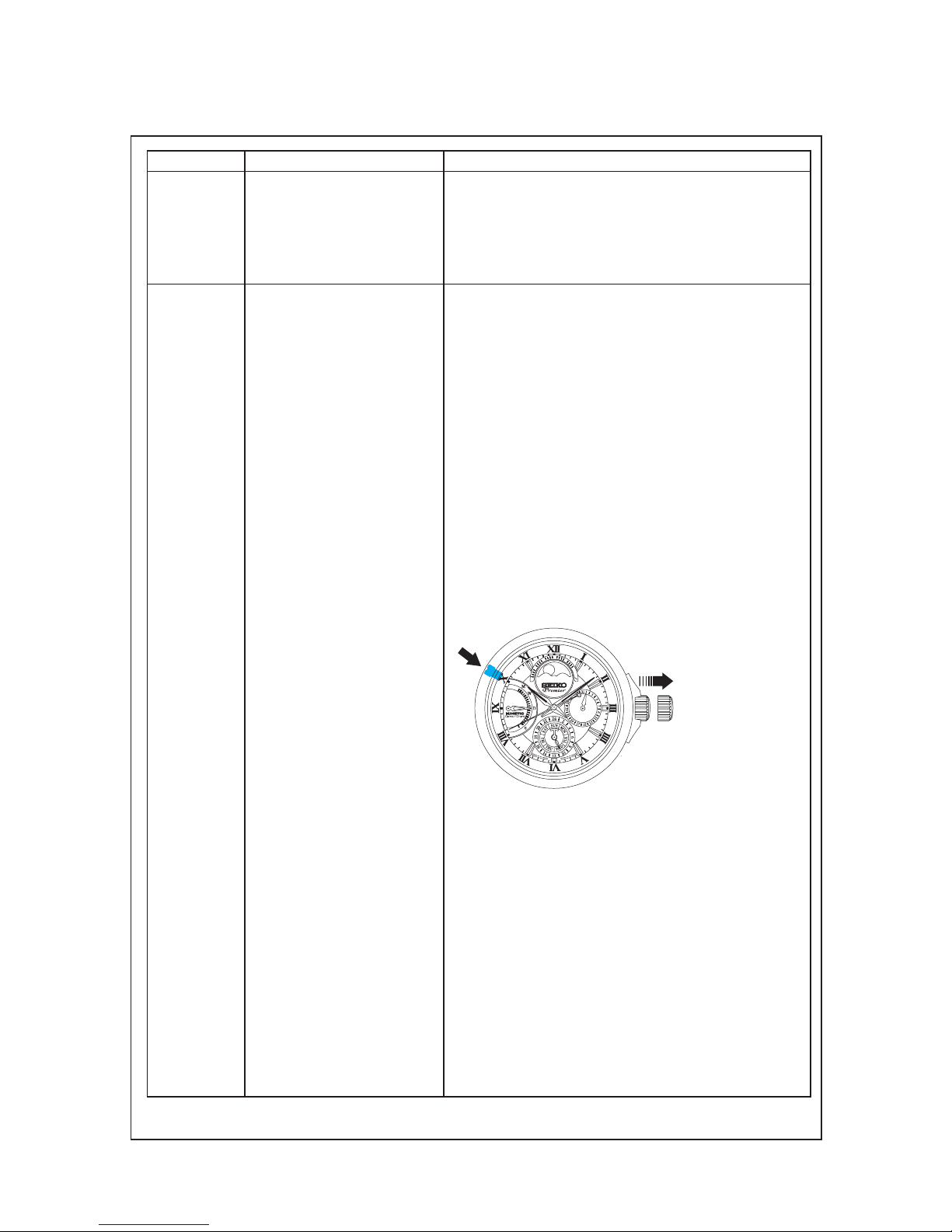
Crown position
Functions by crown operation Functions by button operation
Normal • Electric power generation
by manual winding
Clock wise turn:
charging the watch by
manual winding
Counterclockwise turn:
No function
First click • Calendar setting
Clock wise turn:
day setting
Counterclockwise turn:
date setting
Manual 0 position alignment of the direct drive
indicator hand
The watch automatically corrects the position of the
direct drive indicator hand once ever y 24 hours. While
correcting its position, the direct drive indicator hand
automatically moves, but it is not a malfunction.
How to manually correct the position of the direct
drive indicator hand
• The position of the direct drive indicator hand can be
also corrected by hand.
1. Pull out the crown to the first click.
2. Press the button located at the 10 o’clock position for
2 seconds or more.
By doing this, the direct drive indicator hand returns
to the standby position.
3. Press the button at the 10 o’clock position to set the
position of the direct drive indicator hand pointing
exactly to the 0 position.
15
10
5
0
02
15
25
2
9
1
2
2
With each pressing of the button, the direct drive indicator
hand moves up the scale by one increment. By pressing
the button, adjustment can be made upto the second
increment. At the third pressing of the button, the direct
drive indicator hand returns to the standby position. Repeat
the procedures until the direct drive indicator hand is
correctly aligned to the 0 position.
How to set the Moon Phase
• The moon phase represents the period from the time
when the last new moon occurred to noon of the
current day in day increments.
• The period between new moons is called a “synodic
month,” and its average length is approximately 29.5
days.
* Round off the number of moon phase to the nearest
whole number (Example: 7.8, 8, 24.2, 24)
* Refer to the weather report of your local newspaper
for current moon phase information.
Page 4
BEFORE STARTING REPAIR WORK ON CAL. 5D88A
4/ 51
2. CHARACTERISTICS OF MANUAL WINDING FUNCTION OF KINETIC DIRECT DRIVE
1. As for mechanical watches, the amount of power generated increases in propor tion to the
number of times the mainspring is wound. As for the KINETIC DIRECT DRIVE watches, however,
the amount of power generated by manual winding varies depending on the speed and length of
strokes in which you wind the crown.
The more efficiently the power is generated, the more the direct drive indicator hand moves.
It is even possible to reach the maximum scale value of power reserve with only one stroke.
2. The size of the crown will also affect the amount of power generated by manual winding.
Even if the crown is turned in exactly the same manner, the amount of power generated will vary
depending on the size or the shape of the crown.
Generally, the smaller the crown is, the more efficiently the watch can generate the power.
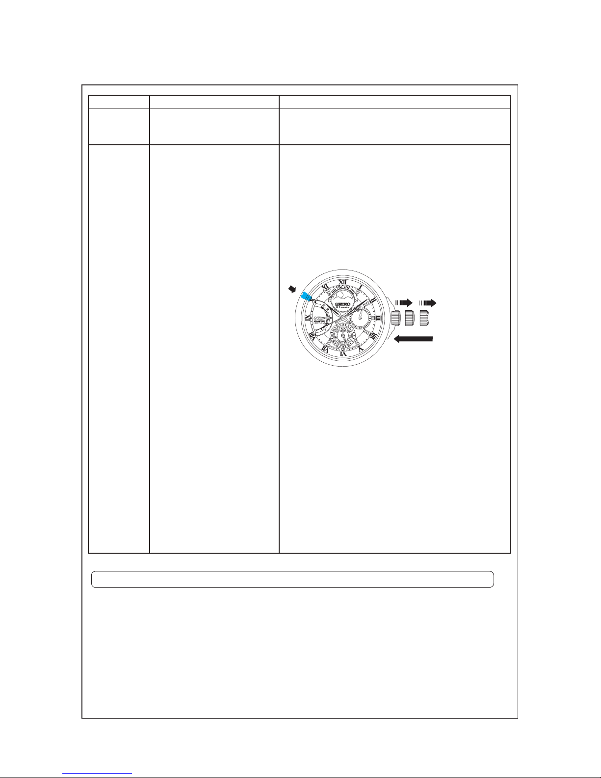
Crown position
Functions by crown operation Functions by button operation
* Do not set the moon phase between 9 pm and 1 am,
as the moon phase may not change to the correct
display on the following day.
Second click • Time setting System reset (No power is generated.)
If any improper function occurs, for example, the direct
drive indicator hand stops moving while it is pointing
anywhere other than the standby position, follow the
instruction below to reset the built-in IC.
1. Pull out the crown to the second click.
2. Press the button at the 10 o’clock position for 2
seconds or more.
3. Push the crown back into the normal position.
15
1
0
5
0
02
15
25
29
1
2
2
After pushing the crown back into the normal position,
charge the watch by manual-winding method and check
that the hands start moving. At the same time the hands
start moving, the direct drive indicator hand will return
to point at the 0 position, and the watch will resume its
normal operation.
After the built-in IC is reset, the continuous operating
time is cleared and the direct indicator hand points at the
0 position. If no power is generated subsequently, the
watch will stop operating within three minutes. In order to
avoid this, charge the watch at least until the direct drive
indicator hand points at the first indication on the dial. It is
also recommended that you correct the position of direct
drive indicator hand manually as instructed on page 3.
Page 5

BEFORE STARTING REPAIR WORK ON CAL. 5D88A
5/ 51
3. HOW THE DIRECT DRIVE INDICATOR HAND WORKS
1. Power reserve indicator function
• Except when the crown is being turned to charge the watch, the direct indicator hand functions
as a power reserve indicator which shows how long the watch will keep operating within the
range between the minimum 3 hours and the maximum 1 month.
For more details, refer to
“ How to read the power reserve indicator” below.
• If the direct drive indicator hand indicates the 0 position, the watch will stop operating within 3
hours. When the watch stops, the direct drive indicator hand moves to the standby position to
show that the watch stops operating due to a power shortage.
• T
he direct drive indicator hand constantly displays the most up-to-date amount of stored
power. If the amount of stored power is increased by the wearer’s wrist movement or by the
manual crown windings, the direct drive indicator hand displays the increased amount of power
accordingly. On the other hand, if the watch is left unworn and the stored power is decreased
as the watch consumed some power during the time it is left unworn, the direct drive indicator
hand displays the decreased amount of stored power accordingly.
•
The
maximum amount of power reserve that the watch can store is the amount of power
reserve to keep the watch operating for one month. When more power is generated after the
watch already stores this maximum amount of power, the power generated is not further
accumulated, and the direct drive indicator hand shows the power reserve of one month.
Scale marking
0 1 2 3 4 5 6 7 8 9 10
Indication on dial
0 D
Power reserve display
0 3h 6h 9h 12h 15h 18h 21h 1 day
Scale marking
11 12 13 14 15 16 17 18 19 20
Indication on dial
W
M
Power reserve amount
2 days 3 days 4 days 5 days 6 days 1W 2W 3W
30days
*note 1
How to read the power reserve indicator
*note 1 Even though the continuous operating time reaches one month, the direct drive
indicator hand remains moving to show that the power generating function is
operating.
• T
he scale marking indicates the minimum continuous operating time.
Scale marking Power reserve
3 3 hours (Not shorter than 3 hours and not longer than 6 hours)
13 4 days (Not shorter than 4 days and not longer than 5 days)
17 2 weeks (Not shorther than 2 weeks and not longer than 3 weeks)
20 *note 1
Page 6
BEFORE STARTING REPAIR WORK ON CAL. 5D88A
6/ 51
*note 1 When the watch is charged by any other method than manual winding, such as using KINETIC
ENERGY SUPPLIER, the direct drive indicator hand may move in slightly slower motion.
*n
ote 2 The direct drive indicator hand will stop at the maximum scale value pointing at the ‘M+1’ position.
If the crown is turned after the direct drive indicator hand stops at the ‘M+1’ position, the watch
continues to accumulate power reserve, but the real-time power indicator function stops. If you
want to display the a
mount of generated power
, stop turning the crown, and after the direct drive
indicator hand returns to the power reserve display, start turning the crown again.
Wh
en the electric power is generated without interruption, for example when an electric charger
is used, the direct drive indicator hand will stop and remain pointing at the ‘M+1’ position.
*n
ote 3 After the direct drive indicator hand displays the accumulated amount of generated power, it
returns to the power reserve display.
(Caution)
To
enjoy the real-time powe r indic ator functio n, power gene ration by manu al wind ing is
recommended as it enables you to check the power generating status.
2.
Real-time power indicator function
How to read the real-time power indicator
Scale marking
0 1 2 3 4 5 6 7 8 9 10
Indication on dial
0 D
Amount of generated power
h=hour(s) min=minute(s)
Standby
position
0
20 min 40 min
1h
1h
20 min1h40 min
2h
2h
20 min2h40 min
Scale marking
11 12 13 14 15 16 17 18 19 20
Indication on dial
W
M
Amount of generated power
h=hour(s) min=minute(s)
3h
3h
20 min3h40 min
4h
4h
20 min4h40 min
5h
5h
20 min5h40 min
6h
<Display and movement flow of the direct drive indicator hand while charging the watch>
Power reserve
display
Power generation status and generated power display
Power reserve display
Initial status
In-progress
A. While turning the crown
B. When temporarily
stopping turning the
crown
After
approximately 4
seconds since
stopping turning
the crown
After
approximately
1 second since
starting to turn
the crown
A B
✽
The direct drive indicator hand points at
a scale marking between 0 and ”M+1”
according to power generation status.
✽
Th
e point where the indicator
hand starts moving goes up as
generated power increases.
Page 7
BEFORE STARTING REPAIR WORK ON CAL. 5D88A
7/51
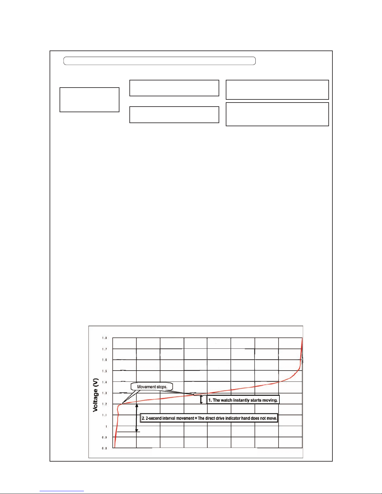
Case 1: The watch has been stopped temporarily.
The watch in this condition falls in the range shown by ‘1. The watch instantly starts moving’ in the
diagram below.
• T
he watch starts operating within a few seconds after you start turning the crown, and
automatically correct the position of the direct drive indicator hand to the 0 position (0
indication on the dial).
• After
the direct drive indicator hand returns to the 0 position, if no further power is generated
subsequently, the watch will stop operating within three minutes.
• T
o prevent the watch from stopping during the subsequent procedures such as time setting
and date setting, charge the watch at least until the direct drive indicator hand points at the first
indication on the dial (3 hours of power reserve).
Ca
se 2: The watch has been left unworn and stopped for a long time. (3 to 5 years or even more)
The watch in this condition falls in the range shown by ‘2. 2-second interval movement = The direct
drive indicator hand does not move’ in the diagram below.
Wh
en the voltage of the rechargeable battery is reduced to an extremely low level after the watch
is left unworn for a long time, the watch moves in 2-second intervals after you start turning the
crown until the voltage is increased to a reasonable level.
Ch
arge the watch by manual winding method until the direct drive indicator hand returns to the 0
position from the standby position.
•
If
power generation is stopped while the watch is moving in 2-second intervals and before the
direct drive indicator hand returns to the 0 position, the watch will stop operating within one
minute.
• E
stimated time required for manual winding to reactivate the watch in this condition:
approximately 5 to 6 minutes
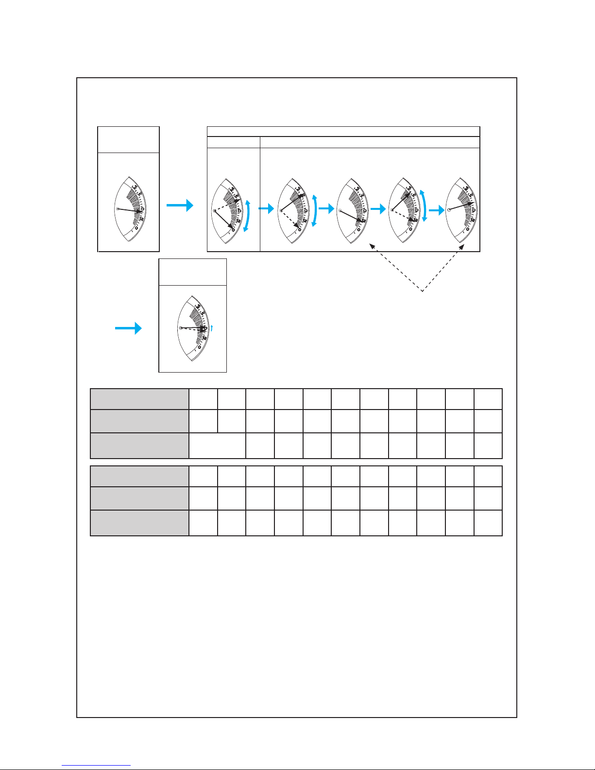
4.
HOW TO REACTIVATE THE WATCH AFTER IT STOPPED
Charge the stopped
watc h manually by
turning the crown.
Th e wa t ch st ar t s ope r a ting
normally within a few seconds.
Th e
wa tch sta r t s o pera ting
in
2-second intervals.
Case 1:
The watch has been stopped temporarily.
Case 2:
Th e wat ch has bee n lef t unw orn f or a
long time.
To reactivate the stopped watch, see the condition of the watch by following the steps below.
voltage and reactivation process diagram
amount of power reserve
a
a
a
a
Page 8

BEFORE STARTING REPAIR WORK ON CAL. 5D88A
8/ 51
Set the crown to the 5D position.
• M a ke sur e th a t the wa t c h is co r r ec t ly
positioned as it may af fec t the amount of
power generated.
• T
he amount of power generated may var y
depending the models of the watch.
• I
n some cases, the dire c t dri ve indi cator
hand does not move.
• I
f the direct drive indicator indicates a fully-charged status, the KINETIC ENERGY SUPPLIER will
continue to charge the watch.
5.
HOW TO CHARGE THE WATCH WITH KINETIC ENERGY SUPPLIER YT-02A
5D
Before setting the KINETIC ENERGY SUPPLIER,
make sure that the watch is moving.
• In some cases, the KINETIC ENERGY SUPPLIER
does not start charging the watches with cal.5D
series when the watch stops.
Page 9

PARTS LIST
Cal. 5D88A
9/ 51
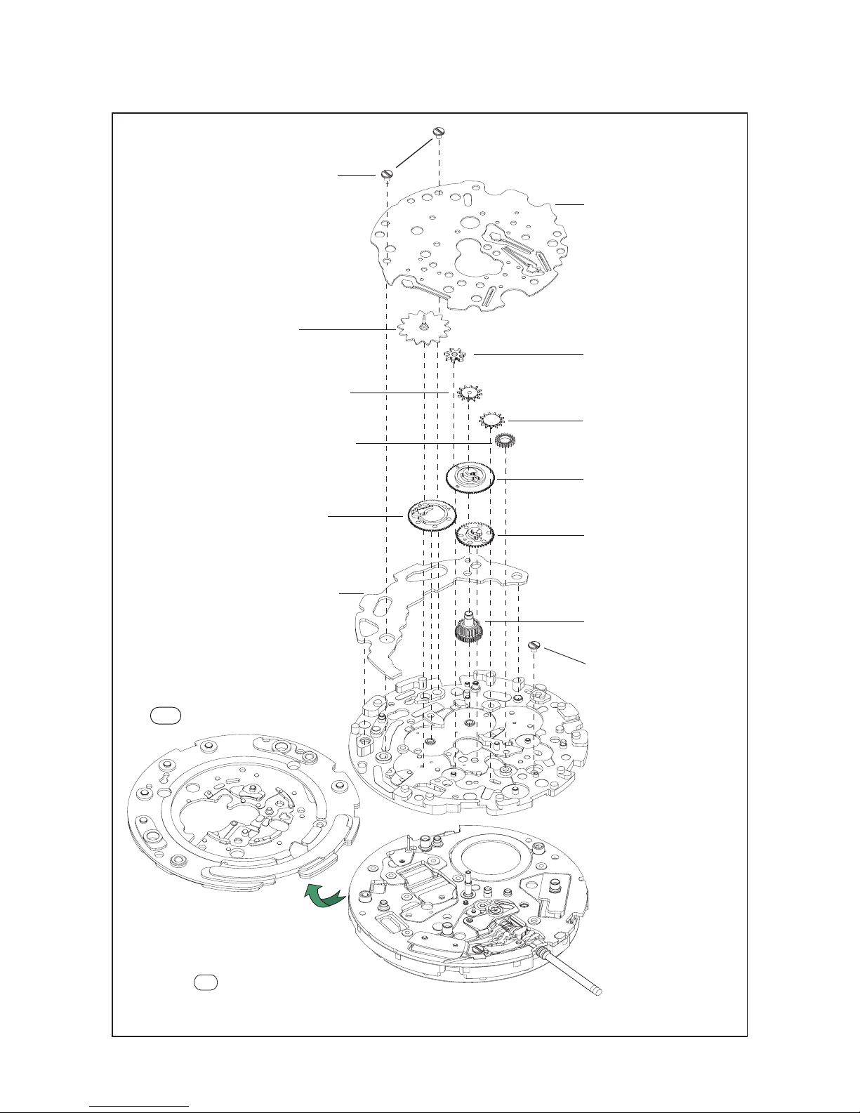
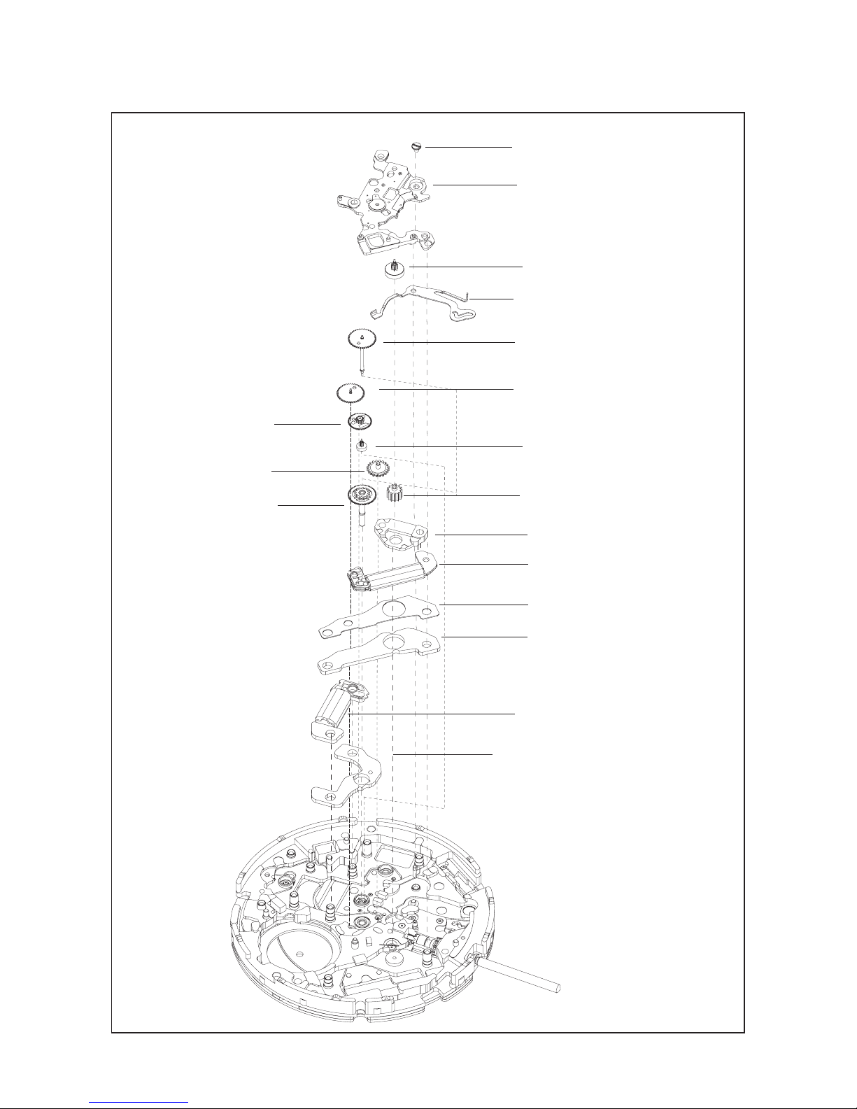
490
20
battery
Oscillating weight screw
0022
Oscillating weight
0500 509
Oscillating weight wheel
1002
Rechargeable battery guard screw
0012 354
Rechargeable battery guard
4225 563
Insulator for rechargeable
4216 546
Rechargeable battery unit
3023 24L
1
2
3
5
6
7
4
Disassembling procedures Figs.:
1
Reassembling procedures Figs. :
1
* For the t ype of oil and quantity of lubrication,
re fe r to the fo ll ow ing TEC HN ICA L GUIDE
section.
ij
ij
[Automatic Generating Mechanism]
Page 10

Cal. 5D88A
PARTS LIST
10/ 51
Calendar train bridge screw
0016704
Dial Washer
Moon phase indicator wheel
0634524
Calendar train bridge
Calendar train bridge screw
0491735
0012354
0439508
Date star wheel
0970501
Date corrector wheel
0804500
Calendar train cover
4283515
24 Hour indicator wheel
1021508
Intermediate wheel for
24 Hour indicator
0817534
Moon phase corrector lever
0595500
qd
qf
qg
qh
qj
qk
8
9
q;
qa
qs
Page 11
PARTS LIST
Cal. 5D88A
11/51
Date jumper
0810503
1026506
1026504
1002531
2nd Intermediate wheel
for day corrector
3rd Intermediate wheel for
calendar corrector
Date driving wheel
Mooh phase indicator
driving wheel
0802514
0271633
Hour wheel
Calendar plate screw
0012354
0271633
Calendar plate
Dammy plate H-G001
* After assemble the oscillating weight bridge,
turn over the movement.
Release the
1026505
1026503
0898500
4259514
1st Intermediate wheel for
day corrector
2nd Intermediate wheel
for calendar corrector
Day driving wheel
Anti-magnetic shield plate
Dummy plate H-G001
32-T
Date jumper screw
0012354
1002529
Day star wheel
w;
ws
wf
wh
wk
e;
ea
es
ql
wa
wd
wg
wj
wl
Calendar plate screw and
ea
remove the
Dummy plate H-G001 and mount
32-T
the
Calendar plate.
es
[Calendar Mechanism]
Page 12
Cal. 5D88A
PARTS LIST
12/51
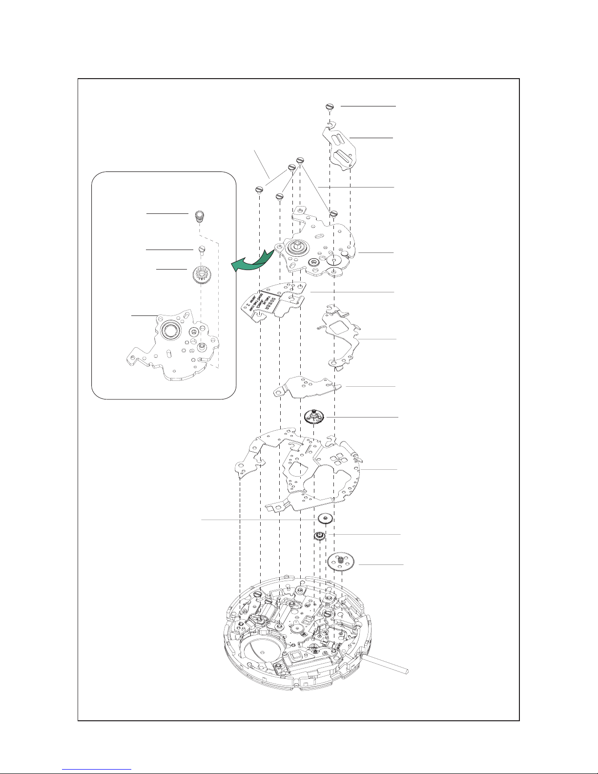
Oscillating weight bridge
screw
Circuit block cover B screw
Oscillating weight bridge
0198 508
Circuit block cover B
4461511
Circuit block cover A
4457 992
2nd intermediate wheel for
manual winding
1026501
Circuit block cover C
4457 994
Switching wheel
1002 518
Circuit block
4000649
3rd intermediate wheel for
manual winding
1026502
1st intermediate wheel for
manual winding
1026500
wheel
Circuit block cover A screw
0012354
Friction spring for sliding
0353527
1002521
Crown wheel fixing
screw
0012354
Crown whee
l
0284500
Oscillating weight
bridge
0198508
Sliding crown wheel
0012354
0012354
ej
ek
r;
eh
ra
rs
rd
rf
rg
rj
rk
rh
eh
eg
ef
ed
el
[Manual Winding Mechanism and Circuit Block]
Page 13
PARTS LIST
Cal. 5D88A
13/ 51
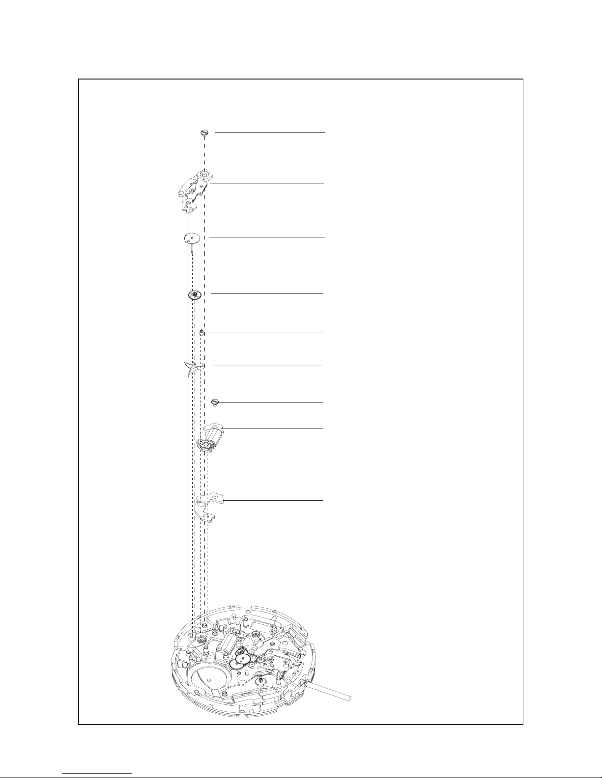
Power reserve coil block screw
0012 354
Power reserve coil block
4002 529
Power reserve train wheel bridge screw
0012 354
Power reserve train wheel bridge
0125 512
Power reserve indicator wheel
1002 522
Intermediate wheel for power reserve
0701 504
Power reserve rotor
4146 502
Power reserve stator
4239 516
Rechargeable
battery connection (+)
4271 627
rl
t;
ta
ts
td
tf
tg
th
tj
[Power Reserve Indicator Mechanism]
Page 14
Cal. 5D88A
PARTS LIST
14/51
Generating rotor
4146 522
Generating stator
4239 542
Spacer for generating stator
4408 562
Coil block
4002 535
Train wheel setting lever
0391503
Fourth wheel
0241565
Third wheel
0231 904
Fifth wheel
0701 504
Rotor
4146886
2nd intermediate wheel
0817 520
Minute wheel
0261 505
Center wheel
0221 594
Rotor stator
4239 541
This part can be found in both silver and
gold color but they are compatible and
there is no difference in their quality and
performance. Spare parts to be supplied
are in silver color.
Train wheel bridge
0125 511
Spacer for coil block rotor
0439 506
Train wheel bridge screw
0012 354
Generating coil block
for minute wheel
tk
tl
y;
ya
ys
yd
yg
yj
yl
u;
ua
us
ud
uf
yf
yh
yk
[Gear Train Mechanism and Stepping Motor]
Page 15
PARTS LIST
Cal. 5D88A
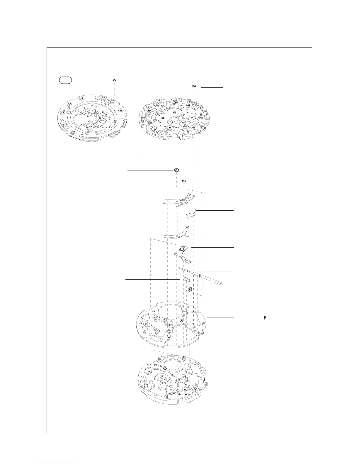
15/51
Calendar
plate screw
0012 354
Calendar plate
4283515
1st intermediate wheel for
0817 519
Setting lever jumper screw
0012 354
Setting lever jumper
0388 500
Setting lever
0383 701
Yoke
0384 502
Switching lever with setting wheel
1017 502
Winding stem
0351 ***
Clutch wheel
0282 505
Winding pinion
0283 500
Main plate
0100 569
Main plate A
4408 571
minute wheel
and intermediate wheel for date
corrector
Mount the Dummy plate instead of
the Calenar plate when assembling
Dummy plate H-G001
32-T
and tighten it
by the Calendar plate screw
Calendar
plate screw
ea
uj
ul
ea
es
uk
i;
ia
is
id
ig
ih
ij
if
[Setting Mechanism]
Page 16
TECHNICAL GUIDE
Cal. 5D88A
16/ 51
1) Pivot portions
Refer to the illustrations A and B.
1. REMARKS ON DISASSEMBLING AND REASSEMBLING
GENERAL INSTRUCTIONS FOR LUBRICATION
Illutration A
Illutration B
2) Part of axis of wheels (generally found on the center wheel and pinion and the fourth wheel.
Refer to the illustrations C and D.
3) S-6 oil on lubricating tool.
Refer to the illustrations E.
Illutration C
Illutration D
Illutration E
Page 17

TECHNICAL GUIDE
Cal. 5D88A
17/51
Front side
Reverse side
• Watch oils
SEIKO watch grease (S-6) and watch oils (AO-3 and AO-2)
S-6
AO-2
AO-3
l
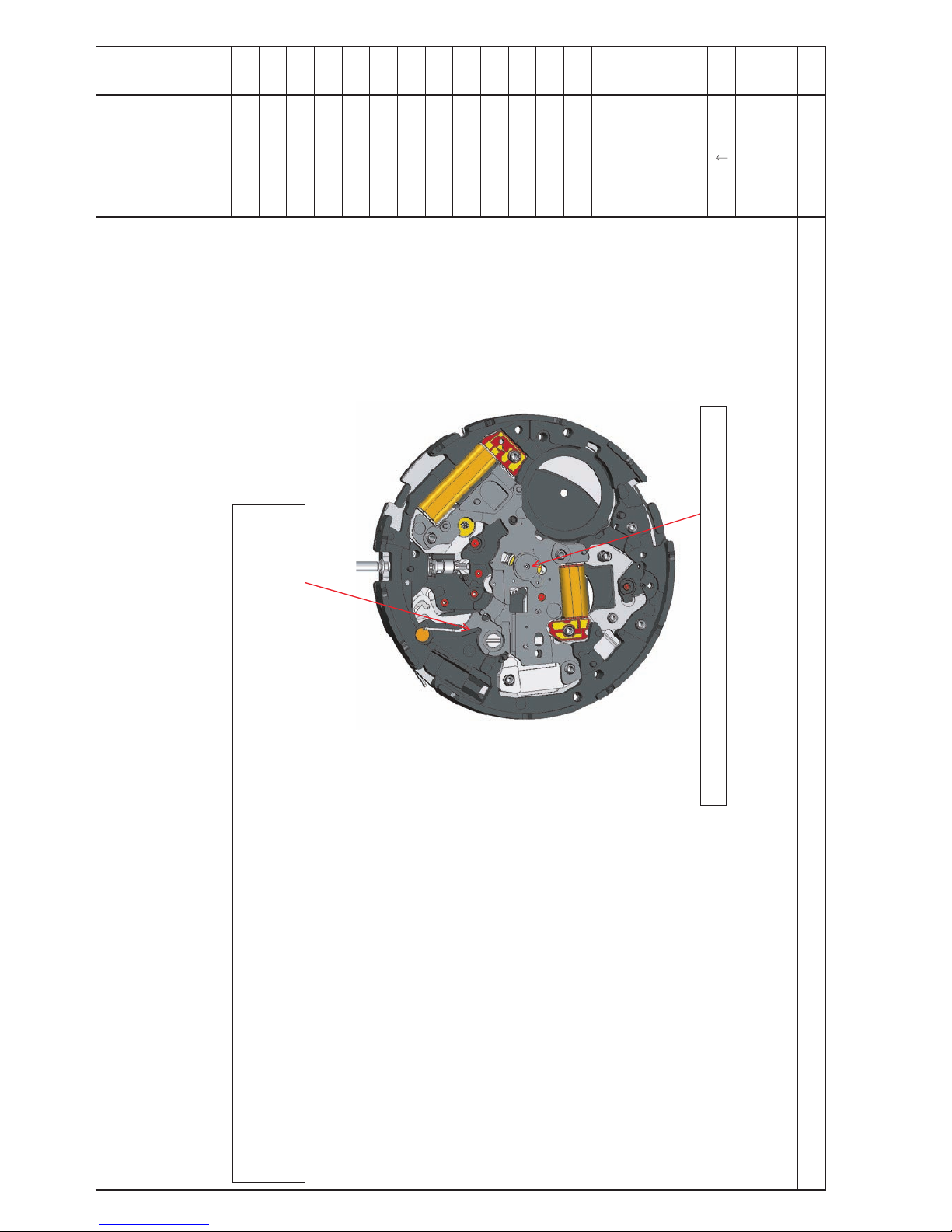
Tools and consumables required for disassembling/reassembling
• 5D Exclusive Movement Holder
2 pins marked with red arrows should be taken out. Even after taking 2 pins out from the
movement holder, it can be used for former 5D calibers.
• UN
IVERSAL MOVEMENT HOLDER
(S-682)
•
Dammy Plate H-G001
Page 18
TECHNICAL GUIDE
Cal. 5D88A
18/ 51
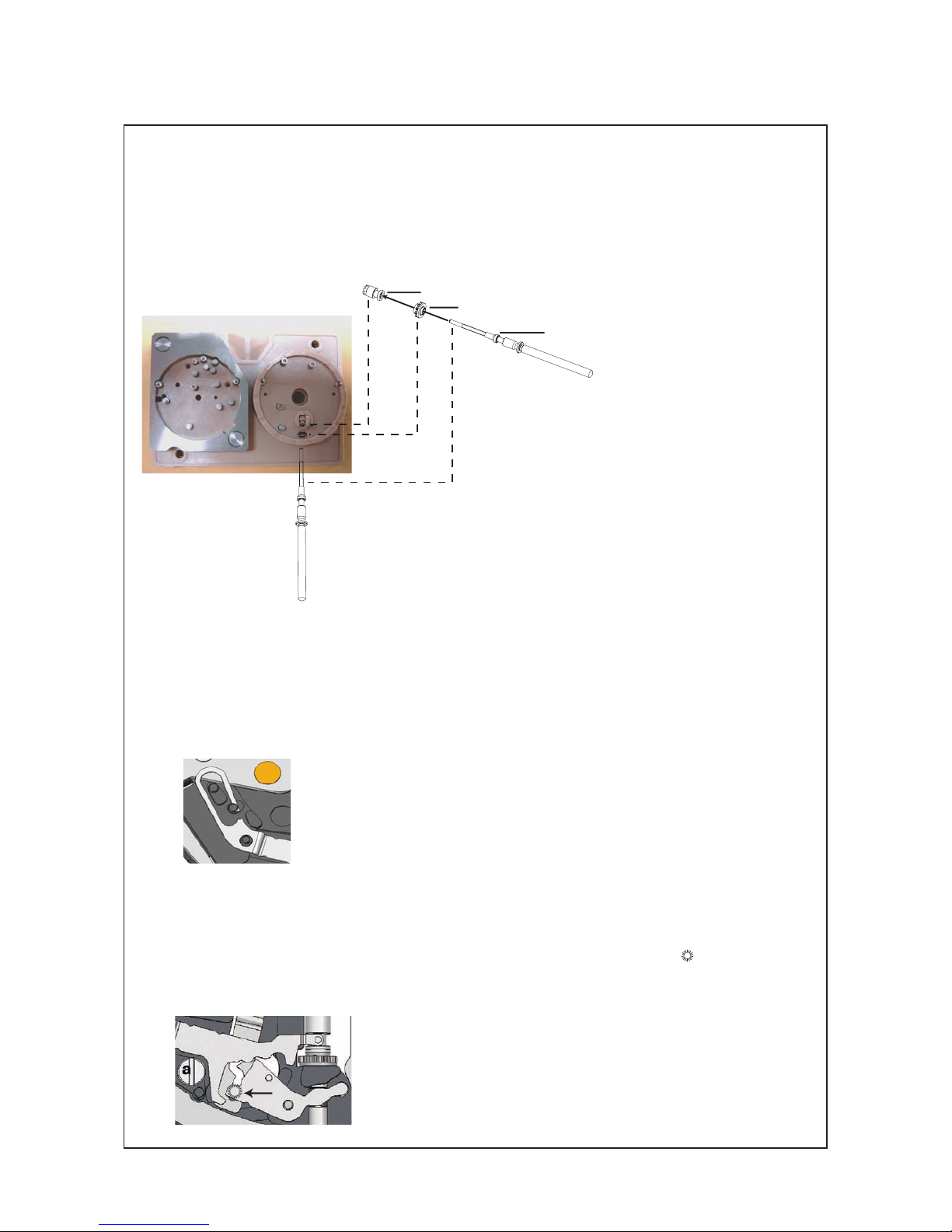
id
Winding stem
iff
Clutch wheel
igg
Winding pinion
Wh
en installing the WINDING STEM, support the WI
NDING PINION and the CLUTCH WHEEL by
using the movement holder as illustrated below.
Winding stem
Winding pinion
if
ig
id
Clutch wheel
ul
Yoke
Se
curely hook the arm of the YOKE inside the pin of the main plate, taking care so as not to
deform the arm of the YOKE.
uk
Setting lever
uj
Setting lever jumper
uh
Setting lever jumper screw
Se
curely engage the pin on the backside of the SETTING LEVER (indicated by
in the illustration
below) with the guiding slit of the SW
ITCHING LEVER. Sliding the SWITCHING LEVER towards the
“a” portion in the illustration below will make this easier.
Page 19

TECHNICAL GUIDE
Cal. 5D88A
19/51
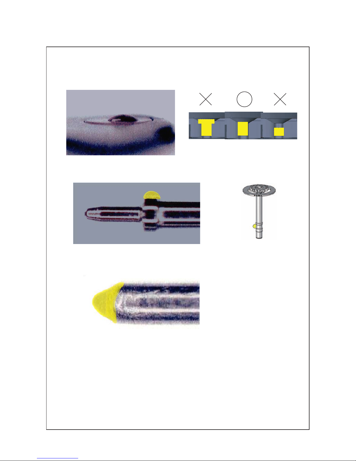
yg
Rotor
Do not mix up the ROTOR ( 65) with the POWER RESERVE ROTOR (53). To discriminate between
the two, see the illustrations below.
rotor (65) power reserve rotor (53)
yj
Second intermediate minute wheel
Do not mount the SECOND INTERMEDIATE WHEEL FOR MINUTE WHEEL (67) upside down. See
the illustrations below to make sure the correct direction.
ya
Train wheel setting lever
Insert the tail portion of the train wheel setting lever with the guiding slit at an angle into the gap
of the circuit bridge, and securely set the guiding slit to the dowel pin of the setting lever.
dowel pin of the setting lever
Hook the arm of the SETTING LEVER after fixing the SETTING LEVER JUMPER by tightening the
SETTING LEVER JUMPER SCREW, taking care so as not to deform the arm of the setting lever.
Page 20

TECHNICAL GUIDE
Cal. 5D88A
20/ 51
td
Power reserve rotor
ts
Intermediate wheel for power reserve
ta
Power reserve indicator wheel
t;
Power reserve train wheel bridge
rl
Power reserve train wheel bridge screw
Check the alignment carefully after mounting the P
O
WER RESERVE ROTOR (53), INTERMEDIATE
WHEEL FOR POWER RESERVE (52) and PO
WER RESERVE INDICATOR WHEEL (51) guided by pins
and built-in magnet on the movement holder before assembling the PO
WER RESERVE TRAIN WHEEL
BRIDGE (50) and PO
WER RESERVE TRAIN WHEEL BRIDGE SCREW (49).
[How to check the alignment]
Af ter tightening the screw, check the alignment of the INT ERMEDIATE WHEEL FOR POWER
RESERVE (52) and PO
WER RESERVE INDICATOR WHEEL (51) once again.
If it is not good, disassemble the parts from the PO
WER RESERVE
TRAIN WHEEL BRIDGE SCREW (49) to the PO
WER RESERVE ROTOR (53) and repeat the same process again. In case the alignment
of wheels and the power reserve rotor is not correct, the direct drive
indicator hand may not be able to indicate the correct value of the
power reserve.
ek
Friction spring for sliding wheel
I
n
se r t the FRICT ION SPRING FOR SLID ING W HEEL ( 3 8 ) bene ath the “ f ” por tion on the
OSCILLATING BRIDGE and securely engage with the dowel without any clearance.
Page 21

TECHNICAL GUIDE
Cal. 5D88A
21/51
2) Direct drive indicator hand
Before installing the direct drive indicator hand, force the direct drive indicator hand position
back to “ 0 ” by resetting the built-in IC (system reset).
[How to retrieve the remaining power reserve (after system reset)]
* A
fter system reset, power reserve indicator goes back to “ 0 ” but the energy is still stored in
rechargeable battery. Instead of using KINETIC energy supplier or manual charging, you can
retrieve the stored energy by following the operations below.
i)
STEP 1
1
. Pull out the crown to the second click position.
2. Hold it for two or more seconds.
3. Repeat the following action within two seconds; [push it back to the normal
position], [pull it out to the second click], [push it back to the normal positon] ,[pull
it out to the second click] and then [push it back to the normal position.]
4.
The hand goes down below "0" shaking, then goes up again toward "D" (*note).
ii) STEP 2
1
. Press the button at the 10 o'clock position.
2. Pull the crown out to the first click position then push it back to the normal
position immediately while holding down the 10 o'clock button.
3.
Af ter confirming that the hand moves up toward "M"(*note), release the 10
o'clock button. (The watch will continue working according to the duration time
indicated.)
within two second
s
*note: depending on the energy level = voltage stored
Page 22
E D I U G L A C I N H C E T A 8 8 D 5 . l a C
1 .ON
l e e h w n w o r c
1.giF
33
7
0
#
s
c
r
e
w
w e r c s g n i x i f l e e h w n w o r c
3 .giF
. w o l e b 3 . g i F e h t n i d e t a c i d n i s a l e e h w g n i h c t i w s e h t e t a c i r b u L ) (
.oN
SSECORP
I
)
A
s
s
e
m
b
l
i
n
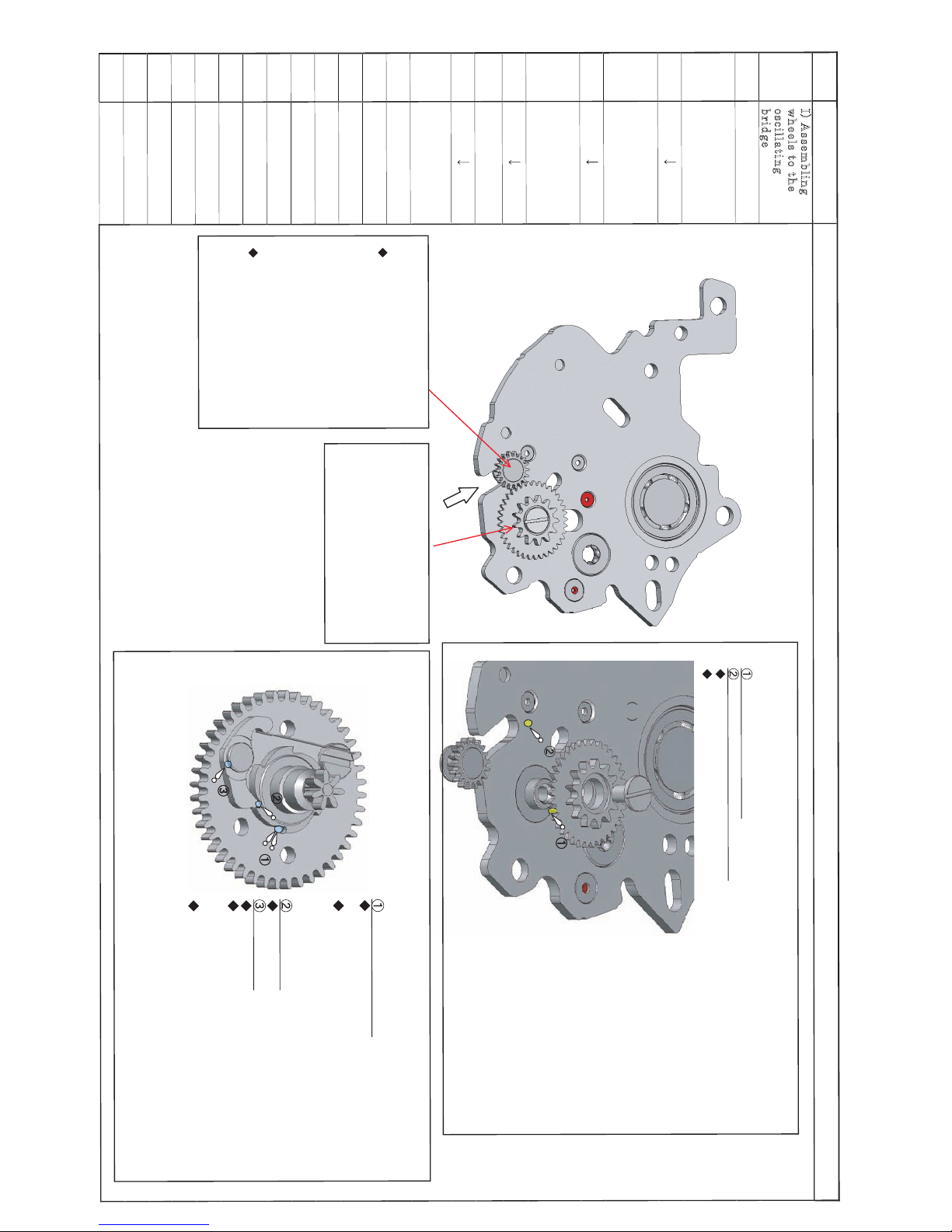
g
w
h
e
e
l
s
t
o
t
h
e
o
s
c
i
l
l
a
t
i
n
g
b
r
i
d
g
e
e h t e t a c i r b u L
t h g i e w g n i t a l l i c s o
e h t o t r e f e R . e g d i r b
. 2 . g i F
35
n w o r c e h t t n u o M
f o s i x a e h t o t l e e h w
g n i t a l l i c s o e h t
. e g d i r b t h g i e w
n w o r c e h t x i F
g n i n e t h g i t y b l e e h w
l e e h w n w o r c e h t
. w e r c s g n i x i f
) (
e h t e t a c i r b u L
. l e e h w g n i h c t i w s
. 3 . g i F e h t o t r e f e R
o t l e e h w n w o r c e h t t n u o M > 35<
t h g i e w g n i t a l l i c s o e h t f o s i x a e h t
. e g d i r b
y b l e e h w n w o r c e h t x i F > 34<
l e e h w n w o r c e h t g n i n e t h g i t
. w e r c s g n i x i f
1 .giF
2 .giF
. w o l e b 2 . g i F e h t n i d e t a c i d n i s a e g d i r b t h g i e w g n i t a l l i c s o e h t e t a c i r b u L
l e e h w n w o r c e h t r o f s i x A
n o i t r o p d e s s e c e r e p a h s - U e h t f o d n E
6 - S : l i o f o e p y T
.ylhtooms nrut leehw
d n a l e e h w n w o r c e h t t a h t e r u s e k a M
e Sliding crown h t t r e s n I > <
d e t a c i d n i n o i t c e r i d e h t m o r F
e
sliding
h t t r e s n i , w o r r a e h t y b
fo dne eht ot
n o i t r o p d e s s e c e r e p a h s - U e h t
t h g i e w g n i t a l l i c s o e h t f o
n e e b s a h 6 - S e r e h w , e g d i r b
x i f y l i r a r o p m e t d n a , d e i l p p a
. 6 - S f o y t i s u o c s i v e h t y b t i
g n i k a e r c g n i k a m t u o h t i w
. s e s i o n
s i x a e h t f o e c a f r u s e d i S
3 - O A : l i o f o e p y T
. e c i w t n o i t a c o l e m a s e h t e t a c i r b u L : e t o N
e c n a r a e l c e h t o t t n a c i r b u l e h t y l p p A
t n a c i r b u l e h t t a h t o s h t e e t e h t h t a e n r e d n u
f o e c a f r u s e d i s e h t o t d e i l p p a y l h g u o r o h t s i
. s i x a e h t
g u l e h t f o p i T
3 - O A : l i o f o e p y T
g u l e h t f o s i x A
3 - O A : l i o f o e p y T
e c n a r a e l c e h t o t t n a c i r b u l e h t y l p p A
s i t n a c i r b u l e h t t a h t o s s i x a e h t d n u o r a
. s i x a e h t f o e c a f r u s e r i t n e e h t o t d e i l p p a
l i o f o t n u o m a e t a i r p o r p p a n a t a h t e r u s n E
s a , s i x a e h t f o t r a p r e w o l e h t o t d e i l p p a s i
e s u a c y a m n o i t a c i r b u l e v i s s e c x e
. s i x a e h t f o s n o i t c n u f l a m
34
33
33
35
44
44
wheel
Make sure that the Sliding
crown wheel smoothly moves
Sliding crown wheel
ILLUSTRATION AND SPECIAL INSTRUCTIONS ETC.
22/51
34
Insert the sliding crown
wheel.
crown wheel
sliding crown
Page 23

E D I U G L A C I N H C E T A 8 8 D 5 . l a C
I
I
) A s s
e
m
b
l
i
n g
t
h
e
d
i a
l
s
i
d
e
o
f
t
h
e
m o v e
m
e
n t
( 1
)
& 87
86
) 85 (
e h t e t a c i r b u L
. n o i n i p g n i d n i w
& 6 . s g i F o t r e f e R
. 7
) (
e h t e t a c i r b u L
. m e t s g n i d n i w
. 8 . g i F o t r e f e R
84 , 85
83 &
g n i d n i w e h t l l a t s n I
n i a M e h t o t m e t s
h c t u l c d n a n o i n i p
. l e e h w
e h t e t a c i r b u L
. r e v e l g n i h c t i w s
9 . g i F e h t o t r e f e R
. 0 1 &
82
e h t t n u o M
. r e v e l g n i h c t i w s
e h t k c e h C (
r e f e R ) . e c n a r a e l c
. 5 . g i F e h t o t
1 8
, e k o y e h t t n u o M
k o o h y l e r u c e s d n a
. g n i r p s s t i
n o i n i p g n i d n i w e h t e t a c i r b u L ) 85 (
. w o l e b d e t a r t s u l l i s a
6 - S : l i o f o e p y T
k o o h y l e r u c e s d n a , e k o y e h t t n u o M > 81 <
. g n i r p s s t i
e d i s n i e k o y e h t f o m r a e h t t e s y l e r u c e S
e r a c g n i k a t , e t a l p n i a m e h t f o n i p e h t
e h t f o m r a e h t m r o f e d o t t o n s a o s
. e k o y
e h t n o e g d i r b t i u c r i c e h t t u P
. l a C r o f r e d l o h t n e m e v o m e h t f o t r a p A
) . w o l e b o t o h p e h t o t r e f e R ( . s e i r e s D 5
e ta l p n i a m e h t t n u o m , n e h t d n A
. e g d i r b t i u c r i c
> <
e h t o t m e t s g n i d n i w e h t l l a t s n I
n o i n i p g n i d n i w h t i w e t a l p n i a m
. l e e h w h c t u l c d n a
) 83 (
3 - O A : l i o f o e p y T
. m e t s g n i d n i w e h t f o e l i f o r p e r i t n e e h t e t a c i r b u L
S
e
t t i
n
g
w h e
e
l
t i l s g n i d i u g e h t f o s a e r a e h t e t a c i r b u L
. w o l e b d e t a r t s u l l i s a
6 - S : l i o f o e p y T
. r e v e l g n i h c t i w s e h t e t a c i r b u L
e t a i d e m r e t n i e h t r o f s i x a e h t e t a c i r b u L
. r o t c e r r o c r a d n e l a c r o f l e e h w
3 - O A : l i o f o e p y T
e c n a r a e l c e h t o t t n a c i r b u l e h t y l p p A
s i t n a c i r b u l e h t t a h t o s s i x a e h t d n u o r a
e c a f r u s e r i t n e e h t o t d e i l p p a y l h g u o r o h t
. s i x a e h t f o
t i g n i v i g , m e t s g n i d n i w e h t l l a t s n i y l e r u c e S
e h t f o e c a f t a l f e h t t a h t o s s n o i t a t o r e l t n e g
e l o h e h t h t i w d e g a g n e e b l l i w m e t s g n i d n i w
. l e e h w h c t u l c e h t f o
d e t a c i r b u l e b o t a e r A
4.giF
5.giF
iF g 7 & 6 .
8 .giF
9 .giF
01 .giF
11 .giF
Mount the switching lever with setting wheel
<82>
the intermediate wheel for calendar corrector and with the setting
Two wheels are attached to the switching lever as illustrated at
right. Check if the switching lever has appropriate clearances with
wheel so that they turn smoothly without making creaking nose.
Intermediate wheel for calendar corrector
83
Lubricate the winding stem
Lubricate the entire profile of the winding stem
Movement holder
A
B
Put the Main plate A
on the A part of the
movement holder
for Cal.5D series.
(Refer to the photo)
And then, mount
the Main plate B to
the Main plate A
plate B with winding
85, 84 & 83
B to the
<87 & 86>
2 . O N
23/51
ILLUSTRATION AND SPECIAL INSTRUCTIONS ETC.
PROCESS
No.
Page 24

E D I U G L A C I N H C E T A 88 D 5 . l a C
3 . O N
.oN
SSECORP
.CTE SNOITCURTSNI LAICEPS DNA SNOITARTSULLI
80
g n i t t e s e h t t n u o M
e h t o t r e f e R . r e v e l
. 3 1 . g i F
f o m r a e h t k o o H
. r e v e l g n i t t e s e h t
. 4 1 . g i F e h t o t r e f e R
, e k o y e h t e t a c i r b u L
d n a r e v e l g n i t t e s
o t r e f e R . s l e e h w
. 5 1 . g i F e h t
d n a r e v e l g n i t t e s , e k o y e h t e t a c i r b u L
. s l e e h w
e k o y e h t n e e w t e b t n e m e g a g n e f o t n i o P
g n i r p s r e v e l g n i t t e s d n a
d n a e k o y e h t n e e w t e b t c a t n o c f o t n i o P
r e v e l g n i t t e s
d n a e k o y e h t n e e w t e b t c a t n o c f o t n i o P
l e e h w h c t u l c
l e e h w h c t u l c e h t f o h t e e t e h t f o s p i T
e h t n e e w t e b t n e m e g a g n e f o t n i o p (
) l e e h w g n i t t e s d n a l e e h w h c t u l c
e t a i d e m r e t n i t s r i f e h t r o f s i x A
3 - O A : l i o f o e p y T
. r e v e l g n i t t e s e h t t n u o M > 80 <
e h t n o n i p e h t e g a g n e y l e r u c e S
r e v e l g n i t t e s e h t f o e d i s k c a b
3 1 . g i F e h t n i y b d e t a c i d n i (
e h t f o t i l s g n i d i u g e h t h t i w ) w o l e b
e h t g n i d i l S . r e v e l g n i h c t i w s
” a “ e h t s d r a w o t r e v e l g n i h c t i w s
e k a m l l i w 3 1 . g i F e h t n i n o i t r o p
. r e i s a e s i h t
a
>79<
> <
. r e v e l g n i t t e s e h t f o m r a e h t k o o H
r e v e l g n i t t e s e h t h s u p t o n o D
m r o f e d y a m o s g n i o d s a , y l e v i s s e c x e
. r e v e l g n i t t e s e h t f o m r a e h t
41 .giF
51 .giF
21 .giF
79
Place the setting lever jumper
Fix the setting lever jumper
by tightening the setting lever
jumper screw.
Fix the setting lever
jumper by tightening
the setting lever
Refer to the Fig.12
Place the setting lever
jumper
Refer to the Fig.12
78
78
jumper screw.
77
Mount the 1st
Intermediate wheel
for minute wheel
Refer to the Fig.12
<77> Mount the 1st Intermediate wheel for minute wheel
This part is reversible
Fig.13
wheel for
minute wheel of the Main plate B
24/51
✽
Page 25
Cal.5D88A TECHNICAL GUIDE
ILLUSTRATION AND SPECIAL INSTRUCTIONS ETC.
NO. 4
32-T
31
Mount the
Fix the Dummy
plate by tightening
the Calendar plate
screw.
Dummy plate
25/51
Fig.16
Fix the Dummy plate to the main plate by
tightening the Calendar Plate screw.<31>
Mount the Dummy plate.
<32-T>
Firmly press down the points of engagement ( “a” and “b” portions)
so that the dummy
Before assembling the case back side of the movement, mount the Dummy plate instead of
a
b
instead of
Calendar plate.
Refer to the Fig.16
the Calendar plate.
(The Calendar plate is thicker, and if the Calendar plate is mounted,
the pins on the movement holder cannot come through the holes of the other side of the
main plate and cannot guide the alignment.)
plate is securely mounted.
PROCESS
No.
Page 26
Cal.5D88A TECHNICAL GUIDE
ILLUSTRATION AND SPECIAL INSTRUCTIONS ETC.
NO.5
I
I
I
)
A s s
e
m
b
l
i
n g
t
h e
c
a s
e
b a c k
s i d
e
o
f
t
h e
m
o
v e m
e n t
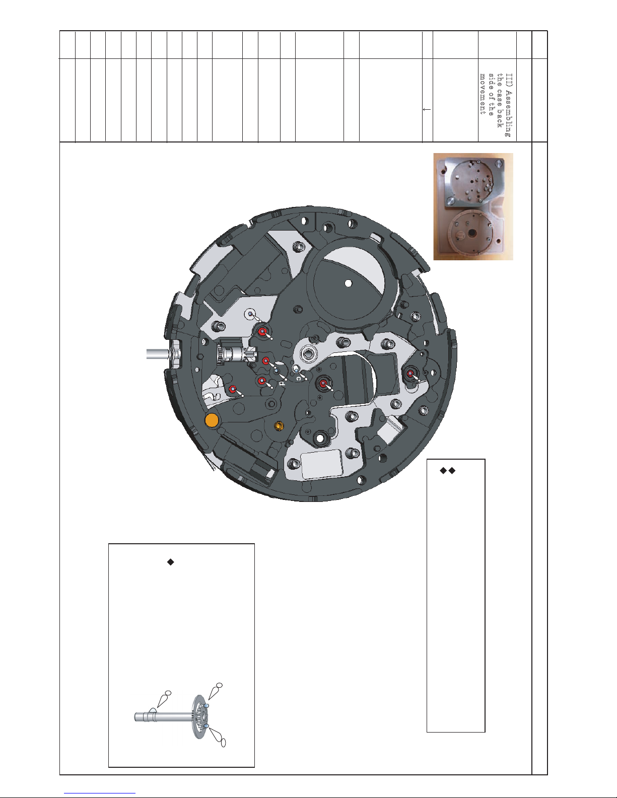
e t a l p n i a m e h t t u P
o t n o n w o d e d i s p u
e h t f o t r a p B e h t
. r e d l o h t n e m e v o m
. o t o h p e h t o t r e f e R
r e w o l e h t e t a c i r b u L
s l e e h w e h t f o s t o v i p
” i “ o t ” a “ m o r f
n w o h s s a s n o i t r o p
. 7 1 . g i F e h t n i
e h t e t a c i r b u L
d n a l e e h w r e t n e c
e h t o t r e f e R . n o i n i p
. 8 1 . g i F
. g i F e h t n i n w o h s ” i “ o t ” a “ m o r f s l e e h w e h t f o s t o v i p r e w o l e h t e t a c i r b u L
. t f e l t a 8 1
2 - O A : ” b “ d n a ” a “ r o f l i o f o e p y T
3 - O A : ” i “ o t ” c “ m o r f l i o f o e p y T
b
a
g f
h
i
e
c
d
71 .giF
81 .giF
) 8 6 (
l e e h w r e t n e c e h t e t a c i r b u L
e h t n i n w o h s s a
. t h g i r t a 8 1 . g i F
3 - O A : l i o f o e p y T
(68)
26/51
PROCESS
No.
A
B
Movement holder
Page 27
Cal.5D88A TECHNICAL GUIDE
ILLUSTRATION AND SPECIAL INSTRUCTIONS ETC.
NO.6
27/51
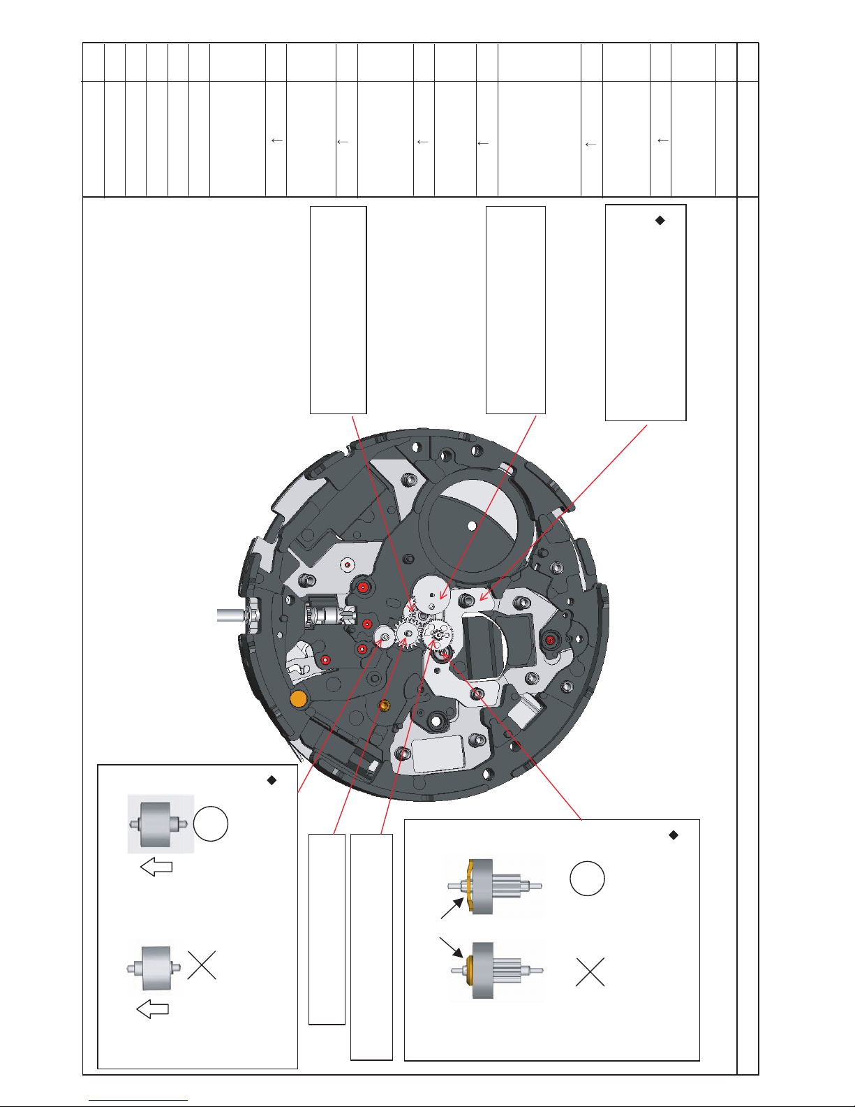
r o t o r e h t t n u o M
. r o t a t s
e h t t n u o M
. l e e h w e t u n i m
. r o t o r e h t t n u o M
. g i F e h t o t r e f e R
. 0 2
h t f i f e h t t n u o M
d n a l e e h w
. n o i n i p
d r i h t e h t t n u o M
d n a l e e h w
. n o i n i p
. r o t o r e h t t n u o M
r o t o r e v r e s e r r e w o p e h t t n u o m t o n o D
r o t o r e h t e t a n i m i r c s i d o T . e k a t s i m y b
e h t e e s , r o t o r e v r e s e r r e w o p e h t m o r f
r o t o r r i e h t f o s e p a h s e h t n i e c n e r e f f i d
. s e g d i r b
. l e e h w e t u n i m e t a i d e m r e t n i d n o c e s e h t t n u o M
e t a i d e m r e t n i d n o c e s e h t t n u o m o t e r u s e k a M
. n o i t c e r i d t c e r r o c e h t n i l e e h w e t u n i m
. r o t a t s r o t o r e h t t n u o M > <
, r o t a t s r o t o r e h t g n i t n u o m n e h W
r o t r o t s i d o t t o n s a o s e r a c e k a t
e s u a c y a m t i s a , t i m r o f e d
. r o t o m e h t f o n o i t a r o i r e t e d
. l ee h w r e t n e c e h t t n u o M
t n u o M e h t e t u n i m . l e e h w
> <
d n a l e e h w d r i h t e h t t n u o M
. n o i n i p
. n o i n i p d n a l e e h w h t f i f e h t t n u o M
) r o t o r e v r e s e r r e w o P (
91 .giF
12 .giF
02 .giF
e g d i r b r o t o r
) r o t o R (
74
Mount the Center
wheel.
68
Mount the Second
Intermediate wheel
for minute wheel.
Refer to Fig.21.
74
67
66
65
<68>
64
63
<65>
65
53
63
<64>
<66>
<67>
PROCESS
No.
Page 28

7 .ON
.oN
SSECORP
62
61
73
72
71
60
70
69
<73>
rotor.
72
g
e n
e
r
a t
i
n
g s t
a
t
o r
3 - O A : l i o f o e p y T
22 .giF
32 .giF
42 .giF
52 .giF
r e v e l g n i t t e s e h t f o n i p l e w o d
Cal.5D88A TECHNICAL GUIDE
ILLUSTRATION AND SPECIAL INSTRUCTIONS ETC.
<62> Lubricate and set the fourth wheel.
Lubricate and set
the fourth wheel.
Refer to the Fig.24
Mount the train
wheel setting
lever.
Refer to the Fig.25.
Mount the coil
block.
Mount the spacer
for generating stator
Refer to the Fig.23.
<61> Mount the train wheel setting lever.
Insert the tail portion of the train wheel setting lever with
the guideing slit at an angle into the gap of the circuit bridge,
and securely set the guiding slit to the dowel pin of the setting
lever.
Mount the
generating coil
block.
Mount the
generating rotor.
Mount the
generating stator.
Refer to the Fig.23.
<69> Mount the spacer for coil block rotor.
Mount the coil block.
When mounting the coil block, take care so as not to
distort or deform the coil blocl core as it may cause
deterioration of the motor.
* Coil block resistance between 1.9KΩ and 2.15KΩ
(as reference value)
<70> Mount the generating coil block.
When mounting thegenerating coil block, take care so as not to
distort or deform the coil block core as it may cause deterioration
of the motor.
* Coil block resistance between 585Ω and 645Ω (as reference value)
<60>
Mount the
generating
rotor.
<72> Mount the spacer for generating stator.
<71> Mount the generating stator.
When mounting the spacer for generating stator and
generating
stator, take care so as not to distort or deform the
coil block
core as it may cause deterioration of the motor.
71
Mount the Spacer
for coil block rotor
28/51
Spacer for generating stator
Page 29
8 .ON
.oN
SSECORP
59
62 .giF
Cal.5D88A TECHNICAL GUIDE
ILLUSTRATION AND SPECIAL INSTRUCTIONS ETC.
Mount the train
wheel bridge and
check the pivot hole.
<59>
Mount the train wheel bridge and check the pivot hole.
69
Fix the train wheel
bridge to the spacer
for coil block rotor
by tightening the
train wheel bridge
screw.
<69>
Fix the train wheel bridge to the spacer for coil block rotor by tightening the train wheel bridge screw.
* Do not overtighten the train wheel bridge screw as doing so may cuase sinking of the train wheel
bridge applying pressure on other parts underneath it, which may result in deterioration of the motor.
29/51
Page 30

9 . O N
.oN
SSECORP
. r o t o r e v r e s e r r e w o p e h t t n u o M > <
f o ) e v i t a g e n d n a e v i t i s o p ( s e i t i r a l o p c i t e n g a m e h t t a h t e r u s e k a M
w o l e b d e t a r t s u l l i s a d e n g i l a e r a r o t o r e v r e s e r r e w o p e h t
t c e r r o c y l l a c i t e n g a m l l i w r e d l o h t n e m e v o m e h t f o s t e n g a m n i - t l i u b e h T *
. r o t o r e v r e s e r r e w o p e h t f o t n e m n g i l a e h t
) k c e h c t n e m n g i l A ( . e v r e s e r r e w o p r o f l e e h w e t a i d e m r e t n i e h t t n u o M > <
) k c e h c t n e m n g i l A ( . l e e h w r o t a c i d n i e v r e s e r r e w o p e h t t n u o M > <
e h t n o ) w o l e b n o i t a r t s u l l i e h t n i y b d e t a c i d n i ( s e l o h g n i n g i l a e h t t e S
n o s n i p g n i n g i l a e h t o t g n i d n o p s e r r o c s n o i t i s o p e h t o t s l e e h w e h t f o e c a f r u s
) . w o l e b . g i F e h t o t r e f e R ( . r e d l o h t n e m e v o m e h t
e v r e s e r r e w o p e h t t l i t , e v r e s e r r e w o p r o f l e e h w e t a i d e m r e t n i e h t g n i t t e s r e t f A
e h t t a h t e r u s e k a M . e v r e s e r r e w o p r o f l e e h w e t a i d e m r e t n i e h t s d r a w o t r o t o r
e v r e s e r r e w o p r o f l e e h w e t a i d e m r e t n i e h t n o k r a m e h t y b d e t n i o p h t o o t r a e g
. r o t o r e v r e s e r r e w o p e h t f o n o i n i p e h t f o h t o o t r a e g a h t i w d e g a g n e y l e r u c e s s i
) . w o l e b . g i F e h t o t r e f e R (
. r o t a t s e v r e s e r r e w o p e h t t n u o M > <
30.giF
g
e a
r
t o o t
h
p
o
i
n
t e
d
b
y
t h
e m a
r k
29 .giF
(
) p
o
w
e
r
r
e
s
e
r
v
e
i
n
d
i c a
t
o
r
w
h
e
e
l
A
l
i
g
n
m e n
t
72 .giF
82 .giF
Cal.5D88A TECHNICAL GUIDE
ILLUSTRATION AND SPECIAL INSTRUCTIONS ETC.
<54>
Mount the
rechargeable
battery
connection (+).
57
Mount the power
reserve stator.
53
Mount the power
reserve rotor.
Refer to the Fig.
28 for the align-
ment of the power
reserve rotor.
52
Mount the
Intermediate wheel
for power reserve.
Refer to the Figs.29
& 30 for the align-
ment of the inter-
mediate wheel for
Mount the power
reserve indicator
wheel. Refer to
the Figs.29 & 30 for
the alignment of the
power reserve
indicator wheel.
51
Mount the
rechargeable
battery
connection (+).
54
57
53
52
51
power reserve.
30/51
51
(52) Intermediate
wheel for power
reserv
(53) Power reserv rotor
29
30
Page 31

01 .ON
.oN
SSECORP
t n e m e v o m e h t e g n a h C
l a s r e v i n u n a o t r e d l o h
. ) 2 8 6 - S ( r e d l o h
e v r e s e r r e w o p e h t x i F
y b e g d i r b l e e h w n i a r t
r e w o p e h t g n i n e t h g i t
l e e h w n i a r t e v r e s e r
. w e r c s e g d i r b
r e p p u e h t e t a c i r b u L
e h t f o s t o v i p
” c “ , ” b “ , ” a “ ( . s l e e h w
r e f e R ) s n o i t r o p ” d “ d n a
. 1 3 . g i F e h t o t
g n i d i u g e h t e t a c i r b u L
lever.g n i t t e s e h t f o t i l s
.giF eht ot refeR
3.
3
r e w o p e h t t n u o M
. k c o l b l i o c e v r e s e r
e v r e s e r r e w o p e h t x i F
y b k c o l b l i o c
r e w o p e h t g n i n e t h g i t
k c o l b l i o c e v r e s e r
. w e r c s
t n e m n g i l a e h t k c e h C
e v r e s e r r e w o p e h t f o
e h t d n a ) 2 4 ( r o t a c i d n i
r o f l e e h w e t a i d e m r e t n i
) 3 4 ( e v r e s e r r e w o p
f o s e l o h e h t h g u o r h t
e g d i r b l e e h w n i a r t e h t
. ) 1 4 (
> < n i a r t e v r e s e r r e w o p e h t t n u o M
. e l o h t o v i p e h t k c e h c d n a e g d i r b l e e h w
b
c
d
a
> < e h t g n i n e t h g i t y b k c o l b l i o c e v r e s e r r e w o p e h t x i F
. w e r c s k c o l b l i o c e v r e s e r r e w o p
l i o c e v r e s e r r e w o p e h t t n u o M > <
. k c o l b
e v r e s e r r e w o p e h t g n i t n u o m n e h W
o t t o n s a o s e r a c e k a t , k c o l b l i o c
e r o c k c o l b l i o c e h t m r o f e d r o t r o t s i d
e h t f o n o i t a r o i r e t e d e s u a c y a m t i s a
. r o t o m
k 5 2 . 1 : e c n a t s i s e r k c o l b l i o C
k 5 . 1 -
) e u l a v e c n e r e f e r s a (
e v r e s e r r e w o p e h t x i F > <
y b e g d i r b l e e h w n i a r t
e v r e s e r r e w o p e h t g n i n e t h g i t
. w e r c s e g d i r b l e e h w n i a r t
e v r e s e r r e w o p e h t n o s e l o h e h t f o s n o i t i s o p e h t t a h t e r u s e k a M
) w o l e b n o i t a r t s u l l i e h t n i y b d e t a c i d n i ( e g d i r b l e e h w n i a r t
e h t n o s e l o h e h t f o s n o i t i s o p e h t o t d e d n o p s e r r o c y l t c i r t s e r a
e v r e s e r r e w o p d n a e v r e s e r r e w o p r o f l e e h w e t a i d e m r e t n i
. l e e h w r o t a c i d n i
I
n
t
e
r
m
e d
i
a
t
e
w
h e
e l
f
o
r
p
o w
e
r
r e s
e
r v e
P
o
w
e
r
r
e
s e
r v
e
i
n
d
i
c a
t
o r
P
o w e r r
e
s
e r v
e
r
o
t
o
r
: e l p m a x e d a B
r e w o p r o f l e e h w e t a i d e m r e t n i e h T
r o t o r e v r e s e r r e w o p e h t d n a e v r e s e r
. d e g a g n e y l t c e r r o c t o n e r a
23 .giF
13 .giF
. g i F e h t o t r e f e r : r e v e l g n i t t e s e h t f o t i l s g n i d i u g e h t e t a c i r b u L
. w o l e b 3 3
3 - O A : l i o f o e p y T
e h t f o t i l s g n i d i u g e h t e t a c i r b u L
r e v e l g n i t t e s
33 .giF
d n a ) 2 4 ( r o t a c i d n i e v r e s e r r e w o p e h t f o t n e m n g i l a e h t k c e h C
e h t h g u o r h t ) 3 4 ( e v r e s e r r e w o p r o f l e e h w e t a i d e m r e t n i e h t
. ) 1 4 ( e g d i r b l e e h w n i a r t e h t f o s e l o h
. s l e e h w e h t f o s t o v i p r e p p u e h t e t a c i r b u L
s n o i t r o p ” b “ d n a ” a “
2 - O A : l i o f o e p y T
s n o i t r o p ” d “ d n a ” c “
3 - O A : l i o f o e p y T
Cal.5D88A TECHNICAL GUIDE
ILLUSTRATION AND SPECIAL INSTRUCTIONS ETC.
50
50
49
49
56
56
55
55
31/51
Mount the power
reserv train wheel
bridge and check the
pivot hole.
Page 32

1 1 . O N
.oN
SSECORP
t s r i f e h t t n u o M
e t a i d e m r e t n i
l a u n a m r o f l e e h w
. g n i d n i w
t i u c r i c e h t t n u o M
. k c o l b
e h t t n u o M
. l e e h w g n i h c t i w s
d r i h t e h t t n u o M
e t a i d e m r e t n i
l a u n a m r o f l e e h w
. g n i d n i w
d n o c e s e h t t n u o M
e t a i d e m r e t n i
l a u n a m r o f l e e h w
. g n i d n i w
. g n i d n i w l a u n a m r o f l e e h w e t a i d e m r e t n i t s r i f e h t t n u o M > <
. k c o l b t i u c r i c e h t t n u o M > <
o t ” a “ m o r f s t n i o p x i s ( s t n e m e g a g n e f o s t n i o p e h t n w o d s s e r p y l m r i F
. 4 3 . g i F e h t n i y b d e t a c i d n i ” f “
> <
. g n i d n i w l a u n a m r o f l e e h w e t a i d e m r e t n i d n o c e s e h t t n u o M
> < g n i d n i w l a u n a m r o f l e e h w e t a i d e m r e t n i d r i h t e h t t n u o M
.
a
f
d
b
c
e
43 .giF
> <
. l e e h w g n i h c t i w s e h t t n u o M
Cal.5D88A TECHNICAL GUIDE
ILLUSTRATION AND SPECIAL INSTRUCTIONS ETC.
48
48
45
44
45
44
47
47
46
46
32/51
Page 33

21 .ON
.oN
SSECORP
t i u c r i c e h t t n u o M
. C r e v o c k c o l b
t i u c r i c e h t t n u o M
. A r e v o c k c o l b
t i u c r i c e h t t n u o M
. B r e v o c k c o l b
e h t t n u o M
g n i t a l l i c s o
n i e g d i r b t h g i e w
d n a I s s e c o r p
t o v i p e h t k c e h c
e h t o t r e f e R . e l o h
. 7 3 . g i F
e h t x i F
g n i t a l l i c s o
e g d i r b t h g i e w
k c o l b t i u c r i c d n a
y b B r e v o c
e h t g n i n e t h g i t
” a “ m o r f s w e r c s
o t r e f e R . ” e “ o t
. 6 3 . g i F e h t
s i e r e h t f i k c e h C
e t a u q e d a n a
o t e c n a r a e l c
l a c i t r e v w o l l a
e h t f o t n e m e v o m
s l e e h w
e h t h t a e n r e d n u
g n i t a l l i c s o
. e g d i r b t h g i e w
. C r e v o c k c o l b t i u c r i c e h t t n u o M > <
t o v i p e h t k c e h c d n a I s s e c o r p n i e g d i r b t h g i e w g n i t a l l i c s o e h t t n u o M > <
. e l o h
n w o r c e h t t a h t e r u s e k a m , e g d i r b t h g i e w g n i t a l l i c s o e h t g n i t t e s n e h W
s i l e e h w n w o r c e h t s a , d e g a g n e y l e r u c e s e r a n o i n i p g n i d n i w d n a l e e h w
t s u j d A . h s e m f o t u o s e o g t i n e h w n o i n i p g n i d n i w e h t e d i r r e v o o t y l e k i l
g n i d n i w e h t f i k c e h C . e s i w k c o l c m e t s g n i d n i w e h t g n i n r u t y b h s e m e h t
. y l h t o o m s s n r u t m e t s
. A r e v o c k c o l b t i u c r i c e h t t n u o M > <
> <
. B r e v o c k c o l b t i u c r i c e h t t n u o M
> <
d n a e g d i r b t h g i e w g n i t a l l i c s o e h t x i F
e h t g n i n e t h g i t y b B r e v o c k c o l b t i u c r i c
. ” e “ o t ” a “ m o r f s w e r c s
O s c i l
l
a t
i
n g
w
e
i
g
h t
b
r i
d g e
T
u
r
n
t h
e w
i
n d i
n
g
s t e
m
c
l
o
c k
w
i s e
t o s e
c u
r e
l
y
e n
g a
g
e t h
e c r
o
w
n
w h
e
e
l
a
n
d w i
n
d
i
n
g p
i n
i
o
n
.
c
e
d
b
a
C
r
o w n
w
h e
e
l
W
i
n
d i
n g
p
i
n i
o
n
53 .giF
63 .giF
73 .giF
Cal.5D88A TECHNICAL GUIDE
ILLUSTRATION AND SPECIAL INSTRUCTIONS ETC.
43
43
42
41
36
39
42
41
39
36
&
40
&
40
33/51
88
88
Page 34

31.ON
e h t e t a c i r b u L
f o s t o v i p r e p p u
r o f s l e e h w e h t
g n i d n i w l a u n a m
e h t t a m s i n a h c e m
s n o i t r o p ” e “ o t ” a “
e h t n i n w o h s s a
. g i F
e h t e t a c i r b u L
e h t f o s g n i r a e b
n w o h s s a s l e e h w
. g i F e h t n i
e h t t r e s n I
r o f g n i r p s n o i t c i r f
l e e h w
” f “ e h t h t a e n e b
n i n w o h s n o i t r o p
. 0 4 . g i F e h t
t i u c r i c e h t x i F
) ( A r e v o c k c o l b
n o i t c i r f e h t d n a
r o f g n i r p s
y b ) (38 l e e h w
e h t g n i n e t h g i t
e h t k c e h C
t n e r r u c
n o i t p m u s n o c
e h t g n i t t e s r e t f a
t i n u y r e t t a b
. y l i r a r o p m e t
e g a p e h t o t r e f e R
. 0 3
r o f s l e e h w e h t f o s t o v i p r e p p u e h t e t a c i r b u L
” e “ o t ” a “ e h t t a ms i n a h c e m g n i d n i w l a u n a m
. 0 4 . g i F e h t n i n w o h s s a s n o i t r o p
3 - O A : l i o f o e p y T
r o f g n i r p s n o i t c i r f e h t t r e s n I > <
n o i t r o p ” f “ e h t h t a e n e b l e e h w
. w o l e b 40 . g i F e h t n i n w o h s
o t n w o d e h t s s e r p y l m r i F
l e w o d e h t h t i w t i e g a g n e y l e r u c e s
t f e l t a 8 3 . g i F e h t n i d e t a c i d n i
o s
y n a t u o h t i w d e t n u o m s i t i t a h t
g n i r p s n o i t c i r f e h t n e e w t e b e c n a r a e l c
g n i t a l l i c s o e h t d n a l e e h w r o f
. e g d i r b t h g i e w
e h t d n a ) ( A r e v o c k c o l b t i u c r i c e h t x i F > <
y b ) ( l e e h w r o f g n i r p s n o i t c i r f
g n i n e t h g i t
f
f
e
c
d
b
a
b
e
a
r
i
n
g s
s a s l e e h w e h t f o s g n i r a e b e h t e t a c i r b u L
. e v o b a .g i F eh t n i n w o h s
3 - O A : l i o f o e p y T
39 .giF
.giF
l e w o d
40 .giF
Cal.5D88A TECHNICAL GUIDE
ILLUSTRATION AND SPECIAL INSTRUCTIONS ETC.
38
38
37
37
34/51
39
39
38
39
PROCESS
No.
sliding
sliding
rechargeable
circuit block cover
A screw.
sliding
38
circuit block cover A screw.
sliding
sliding
42
42
88
Page 35

ILLUSTRATION AND SPECIAL INSTRUCTIONS ETC.
NO. 14
32-T
31
Mount the
Calendar plate
screw.
<32> After removing the Dummy plate, mount
Firmly press down the points of engagement
(217#, 68#)
to securely set it in position.
<31> Fix the Calendar Plate by tightening
Calendar Plate screw (36#).
Target value)
lower than 350gcmTightening torque:
◆
Dummy plate.
Fig.17
Release the Calendar Plate screw.
<31>
a
b
Set the movement
upside down on
the Universal
movement holder.
Release the
Calendar plate
Remove the
32
by tightening the
Calendar plate
Remove the Dummy plate.
<32-T>
After assembling the Oscillating weight bridge, turn
plate before starting to assemble the calendar side
over the movement and disassemble the dummy
of the movement.
the Calendar Plate.
screw.
Cal.5D88A TECHNICAL GUIDE
217#
217#
68#
36#
PROCESS
No.
35/51
Page 36

Cal.5D88A TECHNICAL GUIDE
ILLUSTRATION AND SPECIAL INSTRUCTIONS ETC.
NO.15
PROCESS
No.
Assembling the
Calendar
mechanism
Set the movement
upside down on
the Universal
movement holder.
Pull out the winding
click position.
Lubricating
Mount the Hour
wheel.
Mount the Anti-
magnetic shield
plate (Fig.43).
Mount the Date
driving wheel
Alignment check.
Mount the Day
driving wheel.
Alignment check
Mount the Moon
phase indicator
Alignment check
driving wheel.
30
29
28
27
26
<28>
Mount the Date driving wheel.
Alignment check
After setting the Date driving wheel,
place the hole on the marked point
on the calendar plate (indicated by
in the Fig. 45 below) by turning
the winding stem clockwise.
Lubricating
Lubricate the pipe of the
Center wheel as indicated in
Fig.44 below.
Lubricate the point of contact
the Hour wheel.
between the main plate and
◆
Type of oil: AO-3
(Reducing the resistance by
friction)
<29>
Mount the Anti-magnetic shield plate.
<30>
Mount the Hour
wheel.
<26>
Mount the Moon phase indicator
driving wheel.
Alignment check
◆
◆
<27>
Mount the Day driving wheel.
Alignment check
◆
The top of the triangle mark on
the Moon phase indicator driving
wheel should be set and aligned
within the marked area on the
stem to the 2nd
Fig.44
Fig.45
Calendar plate as indicated in
Fig.47
Fig.47
Fig.46
The peak of the mark on the Day
driving wheel should be set and
aligned within the marked area on
the Calendar plate as indicated in
Fig.46
Fig.43
2
1
1
2
36/51
Page 37

Cal.5D88A TECHNICAL GUIDE
ILLUSTRATION AND SPECIAL INSTRUCTIONS ETC.
NO.16
PROCESS
No.
Mount the 2nd
25
intermediate wheel
for calendar
corrector.
24
Mount the 3rd
intermediate wheel
for calendar
corrector.
23
Mount the 1st
intermediate wheel
for day corrector.
22
Mount the 2nd
intermediate wheel
for day corrector.
21
Mount the Day
star wheel.
<21>
Mount the Day star wheel.
<22>
Mount the 2nd intermediate
wheel for day corrector.
◆
Correct dirrection is as shown
Fig.49 below.
<23>
Mount the 1st intermediate
wheel for day corrector.
<24>
Mount the 3rd intermediate wheel
for day corrector.
◆
To discriminate the 3rd Intermediate
wheel for calendar corrector from the
1st Intermediate wheel for day
corrector, see the difference in the
shapes of each wheel. Fig. 50
*3rd Intermediate
wheel for calendar
corrector
*1st Intermediate
wheel for day
corrector
<25>
Mount the 2nd Intermediate wheel for
calendar corrector.
This part is reversible.
37/51
Fig.49
Fig.49
Fig.48
✽
Page 38

Cal.5D88A TECHNICAL GUIDE
ILLUSTRATION AND SPECIAL INSTRUCTIONS ETC.
NO.17
fi
★★
★
★★
★
★
★★
★
20
Mount the Date
jumper.
19
Fix the Date
jumper to the
calendar plate by
tightening the
Date jumper
screw.
Set and hook the
date jumper to the
day star wheel.
21
<20>
Mount the Date jumper.
◆
Firmly press down the points
of engagement to securely
set it in position. (455#, 456#)
<19>
Fix the Date jumper to the
calendar plate by tightening
the Date jumper screw.
Lubricate the Day
star wheel.
Lubricate the Day star wheel.
◆
◆
Apply the lubricant as shown Fig.53
below.
Type of oil: AO-3 (Reducing the
resistance by friction)
(68#, 101#)
◆
Set and hook the date jumper
to the day star wheel.
Take care so as not to deform
the date jumper.
Check the clear-
ance between the
wheels under the
Date jumper.
Check the clearance between wheels.
2nd Intermediate
wheel for calendar
corrector
3rd Intermediate
wheel for calendar
corrector
1st Intermediate
wheel for day
corrector
2nd Intermediate
wheel for day
corrector
Day driviing wheel
◆
◆
When checking, the Date jumper should be mounted without clearance (hold the point
Target value)
Tightening torque:
lower than 350gcm
38/51
Fig.53
Fig.52
Fig.51
lightly.)
The points of checking are shown in the above illustrations.
5
4
3
2
1
1
2
3
4
5
68#
455#
456#
101#
PROCESS
No.
Page 39

Cal.5D88A TECHNICAL GUIDE
ILLUSTRATION AND SPECIAL INSTRUCTIONS ETC.
NO.18
Set the Moon phase corrector
18
Mount the Moon
phase corrector
lever.
Lubricant
Hook the spring
24
Lubricate the points
of engagement of
the 3rd Inter-
mediate wheel for
calendar corrector.
<18>
Lubricate the Moon phase
corrector lever.
◆
Apply the lubricant as shown
Fig. 56 below.
◆
Type of oil: S-6
Mount the Moon phase corrector
lever. Then hook the spring.
◆
<24>
3rd Intermediate wheel for
calendar corrector
Lubricate the contact point
Fig.55
Fig.56
Fig.57
Fig.54
◆
Take care so as not to deform the
spring.
of the spring.
◆
Apply the lubricant as shown Fig.55
below.
◆
Type of oil: AO-3
39/51
inside the Switch spring.
PROCESS
No.
Page 40

Cal.5D88A TECHNICAL GUIDE
ILLUSTRATION AND SPECIAL INSTRUCTIONS ETC.
NO.19
◆
17
Mount the Inter-
mediate wheel for
24 Hour indicator.
16
Mount the 24 Hour
indicator wheel.
15
Mount the Date
corrector wheel.
Mount the Date
star wheel.
Set and hook the
jumper to Date
star wheel.
14
Mount the
Calendar train
bridge.
13
12
Fix the Calendar
train bridge by
tightening the
Calendar train
bridge screrw.
Check the clear-
ance between the
wheels under the
Calendar train
bridge.
<16>
Mount the 24 Hour
indicator wheel.
<17>
Mount the Intermediate wheel
for 24 Hour indicator.
<15>
Mount the Date corrector
wheel.
<13>
Mount the Calendar train bridge.
◆
Firmly press down the points of
engagement. (451#, 452#)
<12>
Fix the Calendar train bridge by
tightening the Calendar train
bridge screw. (471#)
<14>
Mount the Date star wheel.
Set and hook the jumper to Date
star wheel.
(See Fig.60.)
Take care so as not to deform the
jumper.
◆
Securely engage the Date star wheel
and the Date corrector wheel (indicated
by in the upper left diagram.)
Check the clearance between the wheels.
Date driving wheels
Moon phase
Indicator wheel
◆
Checking points are indicated in Fig.59.
40/51
Fig.58
Fig.59
Fig.60
✻
This part is reversible.
Target value)
Tightening torque:
lower than 350gcm
2
1
452#
471#
451#
1
2
PROCESS
No.
Page 41

Cal.5D88A TECHNICAL GUIDE
ILLUSTRATION AND SPECIAL INSTRUCTIONS ETC.
NO.20
11
Mount the Moon
phase indicator
wheel.
Mount the Dial
washer.
10
9
Mount the calendar
train cover.
Set and hook the
jumper to the Moon
phase indicator
wheel.
9
Fix the calendar
8
train cover by
tightening the
calendar train
bridge screw.
<11>
Mount the Moon phase
indicator wheel.
<10>
Mount the Dial washer.
Make sure the dial washer
◆
is put in the correct direction.
(See the Fig.63 below.)
When mounting the dial
◆
washer, handle it with
care so as not to bend
or deform it.
<9>
Mount the calendar train
cover.
<How to set and hook the jumper
of the Moon phase indicator
◆
Firmly press down the point
of engagement 451# first.
Hook the jumper before
pressing down the engage-
ment 452#. Then, press down
the point of engagement 452#.
◆
Take care so as not to deform
the jumper of the Calendar
wheel>
train wheel.
<8>
Fix the Calendar train cover by
tightening the Calendar train bridge
screw (453#, 454#, 457#.)
◆
When handling the Moon
phase indicator wheel, take
care so as not to damage the
printed surface of the Moon
phase indicator.
Target value)
lower than 200gcmTightening torque:
Lubricate the
jumpers.
Lubricate the jumpers.
Lubricate the jumper of the Date driving wheel
◆
Type of oil: AO-3
Lubricate the jumper of the Day driving wheel
(See Fig.64 shown as right)
◆
Type of oil: AO-3
(See Fig.65 shown as right)
Lubricate the jumper of the Moon phase
Type of oil: S-6
(See Fig.66 shown as right)
indicator driving wheel
◆
(For preventing the abrasion of the parts)
(For preventing the abrasion of the parts)
Fig.61
Fig.62
Fig.63
41/51
Fig.63
Fig.64
Fig.65
Fig.66
3
2
1
1
2
3
452#
454#
451#
457#
453#
PROCESS
No.
Page 42

21 .ON
.oN
SSECORP
e h t t n u o M
. t i n u
e h t t n u o M
r o f r o t a l u s n i
e h t t n u o M
. d r a u g
r o t a l u s n i e h t x i F
n i t l i u b e h t t e s e R
e h t o t r e f e R . C I
. t i n u y r e t t a b y r a d n o c e s e h t t n u o M > <
y r e t t a b y r a d n o c e s e h t f o m r a e h t k o o H
e h t n i n o i t r o p ” a “ e h t o t t i n u
. w o l e b
s u n i m e h t m r o f e d o t t o n s a o s e r a c e k a T
y r a d n o c e s e h t g n i v o m e r n e h w l a n i m r e t
. t i n u y r e t t a b
a
y r a d n o c e s r o f r o t a l u s n i e h t t n u o M > <
. y r e t t a b
e h t f o e l o h e h t n w o d s s e r p y l m r i F
e h t o t y r e t t a b y r a d n o c e s r o f r o t a l u s n i
n e h t , ) ” e “ ( e t a l p n i a m e h t f o e b u t e d i u g
” d “ t n e m e g a g n e f o t n i o p e h t n w o d s s e r p
s i y r e t t a b y r a d n o c e s r o f r o t a l u s n i l i t n u
. n o i t i s o p n i t e s y l e r u c e s
. d r a u g y r e t t a b y r a d n o c e s e h t t n u o M > <
. n o i t i s o p n i t i t e s y l e r u c e s o t t n e m e g a g n e f o s t n i o p e h t n w o d s s e r p y l m r i F
” e “ : e b u t e d i u g g n i n o i t i s o P •
” d “ d n a ” c “ : t n e m e g a g n e f o s t n i o P •
y r e t t a b y r a d n o c e s d n a y r e t t a b y r a d n o c e s r o f r o t a l u s n i e h t x i F > <
. ”f “ d n a ” b “ s w e r c s d r a u g y r e t t a b y r a d n o c e s e h t g n i n e t h g i t y b d r a u g
b
f
e
c
d
. C I n i t l i u b e h t t e s e R
y b C I n i - t l i u b e h t t i u c r i c - t r o h S
e h t n o n r e t t a p t e s e r e h t g n i t c e n n o c
k c o l b t i u c r i c e h t d n a k c o l b t i u c r i c
r o f s r e z e e w t f o r i a p a g n i s u A r e v o c
. s d n o c e s 2 y l e t a m i x o r p p a
S h
o r t - c
i
r c u
i
t
R e
s e t
p
a
t
t
e
r
n
Cal.5D88A TECHNICAL GUIDE
ILLUSTRATION AND SPECIAL INSTRUCTIONS ETC.
7
7
6
6
5
5
4
4
rechargeable battery
rechargeable battery
rechargeable battery
for rechargeable
battery and
rechargeable battery
guard by tightening
the rechargeable
battery guard
screws “b” and “f ”
42/51
Fig.69
Fig.69
Fig.68
Fig.70
Fig.70.
Page 43

. O N
.oN
SSECORP
t e s d n a e t a c i r b u L
g n i t a l l i c s o e h t
. l e e h w t h g i e w
. g i F e h t o t r e f e R
e h t t n u o M
g n i t a l l i c s o
t h g i e w
g n i t a l l i c s o e h t x i F
y b t h g i e w
e h t g n i n e t h g i t
t h g i e w g n i t a l l i c s o
w e r c s
r e w o p e h t k c e h C
g n i t a r e n e g
. e c n a m r o f r e p
e h t k c e h C
e h t f o t n e m e v o m
g n i t a l l i c s o
. t h g i e w
e h t k c e h C
e h t f o t n e m e v o m
. n w o r c
t h g i e w g n i t a l l i c s o e h t t n u o M > <
w e r c s t h g i e w g n i t a l l i c s o e h t g n i n e t h g i t y b t h g i e w g n i t a l l i c s o e h t x i F > 1 <
e.c n a m r o f r e p g n i t a r e n e g r e w o p e h t k c e h C
s i t h g i e w g n i t a l l i c s o e h t e l i h w d e t a r e n e g s i r e w o p e h t f i k c e h C
g n i t a t o r
V 5 5 . 1 d n a V 0 3 . 1 n e e w t e b : e g a t l o v l a i t i n i e h t f o e g n a R
t h g i e w g n i t a l l i c s o e h t g n i n n i p s r e t f a e g a t l o v n i e s a e r c n i e h T
. V m 0 5 n a h t s s e l e b t o n d l u o h s
s i m e t s g i d n i w e h t e l i h w d e t a r e n e g s i r e w o p e h t f i k c e h C
g n i t a t o r
t h g i e w m e t s g n i d n i w e h t g n i t a t o r r e t f a e g a t l o v n i e s a e r c n i e h T
. Vm 0 5 n a h t s s e l e b t o n d l u o h s
. t h g i e w g n i t a l l i c s o e h t f o t n e m e v o m e h t k c e h C
s e t a t o r t h g i e w g n i t a l l i c s o e h t t a h t e r u s n E
. e c n a t s i s e r r o n o i t c i r f y n a t u o h t i w y l h t o o m s
t a e s i w k c o l c t i g n i d n i w y b n w o r c e h t f o t n e m e v o m e h t k c e h C
. n o i t i s o p l a m r o n s t i
t i t a h t d n a e l d i n u r t o n s e o d n w o r c e h t t a h t e r u s e k a M
. e c n a t s i s e r y n a t u o h t i w y l h t o o m s s e t a t o r
. s e s i o n g n i k a e r c g n i k a m t u o h t i w e t a t o r d l u o h s n w o r c e h T
u o y , d e t a c i r b u l y l e t a i r p o r p p a t o n s i r o t o r g n i t a r e n e g e h t f I *
. ) d n u o s h c t i p - h g i h ( g n i k a e r c e h t r a e h l l i w
g n i t a l l i c s o e h t t e s d n a e t a c i r b u L > <
e h t n i n w o h s s a l e e h w t h g i e w
n o i t r o p g n i r p S
3 - O A : l i o f o e p y T
e c n a r a e l c e h t o t t n a c i r b u l e h t y l p p A
e h t t a h t o s g n i r p s e h t f o p i t e h t d n u o r a
e r i t n e e h t o t d e i l p p a s i t n a c i r b u l
. e c a f r u s
s i x A
l e e h w e h t f o n o i t r o p g n i t a l l i c s o
3 - O A : l i o f o e p y T
e c n a r a e l c e h t o t t n a c i r b u l e h t y l p p A
e h t t a h t o s n o i t a t n e d n i e h t d n u o r a
e h t o t y l e r i t n e d e i l p p a s i t n a c i r b u l
. s i x a e h t f o e c a f r u s e d i s n i
Cal.5D88A TECHNICAL GUIDE
ILLUSTRATION AND SPECIAL INSTRUCTIONS ETC.
3
3
2
2
1
43/51
22
Fig.71
Fig.72
Fig.72.
72
.
.
Page 44

EDIUG LACINHCET A88D5.laC
3 2 . O N
SSECORP
).CTE SDOHTEM GNILDNAH ,SNOITACIFICEPS YTILAUQ( SNOITACIFICEPS
V
) F
u
n
c t i
o
n c
h
e
c
k s a
n d
i n
s
t a
l
l a
t
i o n o
f
t h
e
e
x
t
e
r
i
o
r
p
a
r
t
s
f o t n e m e v o m e h t k c e h C
d n a m e t s g n i d n i w e h t
. s l e e h w d e t c e n n o c
. n o i t i s o p y n a t a d e g g a r d g n i e b t u o h t i w y l h t o o m s s k r o w m e t s g n i d n i w e h t t a h t e r u s n E
• . a s r e v e c i v d n a n o i t i s o p k c i l c d n o c e s d n a t s r i f e h t o t m e t s g n i d n i w e h t t u o l l u P
• . n o i t i s o p h c a e t a e s i w k c o l c r e t n u o c d n a e s i w k c o l c n w o r c e h t n r u T
f o t n e m e v o m e h t k c e h C
g n i d n i w y b s d n a h e h t
t a n w o r c h t i w m e t s e h t
k c i l c d n o c e s e h t
. n o i t i s o p
. n o i t c i r f y n a t u o h t i w r o g n i t a t o r e l i h w d e g g a r d g n i e b r o f f o g n i p p o r d t u o h t i w y l h t o o m s e v o m d l u o h s s d n a h e h T
d n a e t a d e h t f i k c e h C
n e h w d e t c e r r o c e r a y a d
t s r i f e h t t a s i n w o r c e h t
. n o i t i s o p k c i l c
. e c n a t s i s e r r o n o i t c i r f y n a t u o h t i w y l h t o o m s d e t c e r r o c s i r a d n e l a c e h t t a h t e r u s n E
. leehwrats yad dna e t a d e h t h t o b f o n o i t a t o r l l u f k c e h C
d n a e t a d e h t f i k c e h C
y l t c e r r o c e g n a h c y a d
e h t t a s i n w o r c e h t n e h w
. n o i t i s o p k c i l c d n o c e s
yad e, t a d e h t t a h t e r u s n E
. d e g g a r d g n i e b t u o h t i w y l t n a t s n i e g n a h c d l u o h s y a d d n a e t a d e h T
. e m i t e n o t a s y a d o w t r o f e c n a v d a t o n s e o d t i t a h t e r u s e k a m , s e g n a h c e t a d e h t n e h W
. t s 1 e h t o t y a d h t 7 e h t m o r f y l t n a t s n i d n a y l t c e r r o c s e g n a h c y a d e h t t a h t e r u s e k a M
44/51
and Moon phase correctly changes without any friction or resistance.
leehwrats
Ensure that the Moon phase indicator wheel moves correctly and
smoothly.
Check if the Moon phase
indicator wheel move
correctly when the 18
Moon phase corrector
lever is pushed.
Page 45

E D I U G L A C I N H C E T A 8 8 D 5 . l a C
42 .ON
.oN
SSECORP
).CTE SDOHTEM GNILDNAH ,SNOITACIFICEPS YTILAUQ( SNOITACIFICEPS
.CTE SNOITCURTSNI LAICEPS DNA SNOITARTSULLI
laid eht tnuoM
.rehsaw
.ti mrofed ro dneb ot ton sa os erac ekaT
eht tnuoM
.laid rof eceip-dne
.laid eht tnuoM
ta 46 .giF eht ot refeR .”b“ dna ”a“ ta snip gnixif laid rof seloH
.thgir
eht kcehC
eht fo ecnaraelc
.leehw ruoh
rof noitaraperP
eht gnitnuom
evird tcerid
dnah rotacidni
).thgir ta noitcurtsni eht ot refeR(
b
a
P
r
e
p
a
r
a t
i
o
n
f
o
r
m
o
u
n
t
i
n g
t h
e
d
i
r
e c
t
d
r i
v
e
i
n
d
i
c
a
t
o
r
h a n d
0 e h t o t s n r u t e r y l i r a r o p m e t d n a h r o t a c i d n i e v i r d t c e r i d e h t , t e s e r s i C I n i - t l i u b e h t n e h W
. s e t u n i m 9 m u m i x a m f o d o i r e p a r o f e r e h t s n i a m e r d n a n o i t i s o p
. s e t u n i m 9 f o t i m i l e m i t s i h t n i h t i w s e r u d e c o r p g n i w o l l o f e h t t u o y r r a C
<
H
o w
t
o i
n
s t a
l
l
t
h
e
d
i
r
e
c
t
d r
i
v
e i
n
d
i
c
a
t o
r
h
a
n
d
a
f t e
r
r e
s e
t
t
i
n
g
t
h
e b
u
i
l
t
- i
n I
C >
k c o l c ’ o 0 1 e h t t a d e t a c o l n o t t u b e h t s s e r p , n o i t i s o p d n o c e s e h t t a m e t s g n i d n i w e h t h t i W . 1
. e r o m r o s d n o c e s 2 r o f n o i t i s o p
k c a b m e t s g n i d n i w e h t h s u p n e h t d n a , e r o m r o s d n o c e s 2 r o f t i a w , n o t t u b e h t g n i s a e l e r r e t f A . 2
e v i r d t c e r i d e h T . n o i t a r e p o t e s e r m e t s y s e h t r e g g i r t l l i w s i h t g n i o D . n o i t i s o p l a n i g i r o e h t o t
. ) n o i t i s o p y b d n a t s ( n o i t i s o p 0 e h t o t s n r u t e r d n a h r o t a c i d n i
. s d n a h e h t g n i t n u o m t r a t s d n a n i a g a n o i t i s o p d n o c e s e h t o t m e t s g n i d n i w e h t t u o l l u P . 3
e h t , n o i t i s o p k c i l c t s r i f e h t t a r o n o i t i s o p l a n i g i r o e h t t a s i m e t s g n i d n i w e h t f I ) e t o N
3 y l n o r o f n o i t i s o p y b d n a t s e h t t a g n i y a t s s n i a m e r d n a h r o t a c i d n i e v i r d t c e r i d
. t e s e r s i C I n i - t l i u b e h t r e t f a s e t u n i m
iF g 46 .
66 .giF
45/51
Page 46

Cal.5D88A TECHNICAL GUIDE
NO. 25
46/51
No. PROCESS
SPEC IFIC ATIO NS (QUALITY SPE CIFIC ATIONS, HA NDLING ME THODS ETC.)
ILLUSTRATIONS AND SPECIAL INSTRUCTIONS ETC.
Mount the direct drive
indicator hand.
The direct drive indicator hand should indicate the “0” position
as illustrated at right.
Push-in force: push it in with a force less than 2 kg.
Mount the date hand. Set the date hand to the appropriate date scale.
Mount the 24H hand.
Make sure that the date hand moves properly when turning
the crown at the second click position. Then mount the 24H
hand to the 24H position.
Mount the day hand.
Mount the hour hand.
Mount the minute
hand.
Mount the second
hand.
Check the hand
installation height.
Make sure that the hands turn a full circle without having any
friction with other hands or markings on the dial or the
surface of the dial.
Check the movement
of the hands.
Check if the date and
day change correctly.
Remove the winding
stem.
Set the movement into
the case.
Ensure that the case is firmly mounted without any clearance.
Set the winding stem
with the crown.
Close the case back.
24H hand
Date hand
Day hand
Direct drive indicator hand
Page 47

TECHNICAL GUIDE
Cal. 5D88A
47/51
2. VALUE CHECKING AND ADJUSTMENT
l
Coil block resistance
Measure the resistance of each coil block and make sure that each measured value falls in the
range as below.
C
oil block: 1.9kΩ – 2.15k
Ω
G
enerating coil block: 585Ω – 645
Ω
Po
wer reserve coil block: 1.25kΩ – 1.50kΩ
l Cu
rrent consumption
For the whole movement: Less than 0.65μA (with the supplied voltage range between 1.25V and
1.45V from the rechargeable battery)
* The above information is provided only as reference.
Please
note that the current consumption value may slightly vary each time you
measure it, depending on the model of the watch (hand specification, or moment of
inertia).
* When using a SEIKO multi-tester S-860, select the following range.
For the whole movement: NORMAL 40 μA
l
Ho
w to measure the current consumption
1. R e move the os c illat i n g we ight ,
in s ul a to r fo r th e re c ha r g e a b l e
ba t tery and rec har geable ba t tery
cover.
2.
R e move th e se c o nda r y ba t te r y
and ro t a t e it approxim a te l y 180
degrees, then place it in a temporary
po sition for current cons umption
measurement as illustrated.
3. Measure the voltage of the rechargeable bat tery and make sure the result falls in the range
between 1.25V and 1.45V. If the result is out of the range, please replace the rechargeable
bat ter y and check the volt age a gain (Af ter chec king the current c ons umpti on, you c an
reassemble the original rechargeable battery as it does not mean the bat tery itself has a
failure).
4
.
Pull out the crown to the second click position.
5. Apply each probe of the tester to the (- ) and (+) terminal of the movement as illustrated.
Avoid touching metal part other than the terminals by the probes so as not to short-circuit the
rechargeable battery.
6.
Hold the probes for 2 seconds or more, then push back the crown into the normal position.
7. Wait for approximately 20 to 30 seconds until the current consumption becomes stable. When
the current consumption shows stable measurements, read the measurement.
Page 48

TECHNICAL GUIDE
Cal. 5D88A
48/51
Initial voltage Guideline of normal/defective decision
1.05V - 1.55V Af ter charging, the voltage of the rechargeable
battery increase more than 0.05 from the initial
voltage.
* The
guidelines specified in the above table is applicable only when the voltage of the
rechargeable battery is within the range between 1.05 V and 1.55 V.
* The
amount of electricity generated by swinging the watch varies depending on the
manner in which you swing it, such as the rate of swinging and the size of the swinging
arc. Please note, therefore, that checking through the procedure above is provided only
as a guideline of normal/defective decision.
*
I
f the current consumption keeps going down or exceeds the standard value, repeat
the procedure from the step 4 above.
l Ch
ecking the automatic generating system
1. Apply the probes of the tester as shown in the illustration, and measure the voltage of the
rechargeable battery. (The obtained voltage is called the initial voltage.)
Notes:
• W
hen applying the minus probe of the
tester to the rechargeable battery, take care
so as not to short-circuit the lead terminal (-)
and the rechargeable battery clamp.
•
I
f a short-circuit has occurred, leave the
watch untouched for more than 10 minutes,
and measure the voltage again, checking
that a stable measurement is obtained.
2
.
Close the case back tentatively, and swing the watch
from side to side 200 times at a rate of 2 to 3 swings
a second, making an arc of approximately 20 cm.
3.
Within 3 minutes af ter swinging the watch, measure
the voltage of the rechargeable battery. in the same
manner as in step 1 above.
4.
Refer to the table below, and decide whether the
automatic generating system is normal or defective.
[Initial voltage of the rechargeable battery and guidelines of normal/defective decision]
Page 49

TECHNICAL GUIDE
Cal. 5D88A
49/51
<Notes on generating power and power reserve amount >
l
Number of swings and power reserve
• W
hen the power reserve in the rechargeable battery is depleted and the watch stops
completely, swing the watch for a few seconds at a rate of 2 to 3 times a second, and then check
if the direct drive indicator hand moves to the 0 position from the standby position. After the
direct drive indicator hand returns to the 0 position, charge the watch either by manual winding
or by swinging the watch, observing the movement of the direct drive indicator hand.
•
I
f the direct drive indicator hand remains moving at 2-second intervals, swing the watch
approximately 500 times at a rate of 2 to 3 times a second. By doing so, the direct drive
indicator hand will start moving at 1-second intervals.
If the
direct drive indicator hand still remains moving at 2-second intervals after this, continue
swinging the watch further until the second hand starts moving at 1-second intervals.
*
After the direct drive indicator hand resumes its 1-second-interval movement, if no
further power is generated subsequently, the watch will stop operating within three
minutes. While the direct drive indicator hand is moving at 2-second intervals, and no
further power is generated, the watch will stop operating within one minute.
l
Number of crown turnings and power reserve
• T
urning the crown 60 times within approximately one minute will generate the power reserve of
approximately 6 hours.
* The
amount of power generated by manual winding varies depending on the manner
in which you turn the crown, such as the speed or the length of strokes of turning the
crown.
Page 50

TECHNICAL GUIDE
Cal. 5D88A
50/51
3. TROUBLESHOOTING
The watch stops operating.
1) The battery voltage has been
depleted.
2) The coil is broken.
3)
O n e or mo r e whe e ls hav e
been contaminated with dirt,
dust or other particles.
A
n exce s sive or insu f f icient
amount of lubricant has been
applied to the wheels.
Symptom Possible causes Solutions
The oscillating weight rotates
at an abnormally high rate,
and no charging is made.
1) The coil of the generating coil
block is broken.
2)
T he piv ot of the g e nera ting
rotor is broken.
(
The pinion of the generating
r o t or an d th e ge a r of t h e
i n t e r m e d i a t e w h e e l f o r
gen e r ating roto r ar e out of
mesh.)
1
)
Ch e ck t he r esistan c e o f the
generating coil block. If the
coil is broken, rep l a c e th e
generating c oil bloc k with a
new one.
2
)
R em o v e th e b r o ke n pi e c e
of the generating roto r, and
rep l a c e the gener a t ing c o il
blo c k wit h a ne w one an d
lubricate it appropriately.
(
O v er h au l an d c l ea n th e
relevant parts if necessary.)
1)
Charge the watch.
2) Replace the coil wit h a new
one.
3)
Remove dirt or dust and clean
the co n t a mi na ted whe e l s.
Lubricate the relevant wheels
wi th appropriat e amount of
lubricant.
The o scillating weight does
not rotate.
1)
The ge a r of t h e os c i l la t ing
weight and the pinion of the
intermediate wheel are out of
mesh.
2)
T he piv ot of the g e nera ting
rotor is broken.
(
The pinion of the generating
r o t or an d th e ge a r of t h e
i n t e r m e d i a t e w h e e l f o r
gen e r ating roto r ar e out of
mesh.)
1) If the gear of the o scillating
weight and the pinion of the
intermediate wheel are intact,
reassemble them correctly.
2
)
R em o v e th e b r o ke n pi e c e
of the generating roto r, and
rep l a c e the gener a t ing c o il
blo c k wit h a ne w one an d
lubricate it appropriately.
(
O v er h au l an d c l ea n th e
relevant parts if necessary.)
The current consumption for
the move ment exc eeds t he
standard value.
1)
When the me a s u r e m e n t is
ma d e , the IC is still in th e
quic k st ar t mo d e . ( Whe n
th e c u r r e nt co n su m pt i on
measures about 20 0μA , it is
likely that the IC is in the quick
start mode.)
2)
The load applied on the gear
train has increased, and the
driving pulse to compensate
it has been generated.
1)
Af ter connec t ing the tes ter,
t u r n t h e c r o w n s e v e r a l
times, and then, make the
measurement again.
2 ) Ov e r h au l an d c l ea n t he
mov e m e n t par t s, and th e n
make the measurement again.
The date star wheel does not
rotate.
The day star wheel does not
rotate.
1
)
The day s tarr wheel/the date
staar wheel and each jumper
are disengaged.
2
)
T h e d a y s t a r w h e e l / t h e
d a te s t ar w h e e l an d e a c h
i n t er m e d i a t e w he e l a r e
disengaged.
Check the clearance of the date
star wheel and day star wheel.
Correct the defected parts.
Page 51

TECHNICAL GUIDE
Cal. 5D88A
51/51
©2010 by
The crown falls off.
Small amount of wate r/blur
inside of the glass persists.
Water resistance is deteriorated.
The watch has been subjected to
water pressure that exceeds the
guaranteed degree.
Inves t igat e t he cau s es to take
n e c e s s ar y me a su r e s , w h il e
cleaning inside of the watch.
Symptom Possible causes
Solutions
The di r e ct drive i n d i cator
hand does not move.
1
)
The battery voltage has been
depleted.
2)
The coil is broken.
3) On e or mor e whe e l s hav e
been contaminated with dirt,
dust or other particles.
A
n exce s sive or insuf fi cie nt
amount of lubricant has been
applied to the wheels.
1) Charge the watch.
2) Replace the power reserve coil
with a new one.
3) Remove dirt or dust and clean
the co n tam i n a ted wh e els .
Lubricate the relevant wheels
wi th approp ria te amoun t of
lubricant.
The dire c t dr i ve in d i cato r
hand is not correctly aligned.
1) The direct drive indicator hand
has been incorrectly mounted
to the wrong position.
2 )T h e po s i tio n of the po w e r
reser v e related wh e e l s are
incorrect.
1
)
Ch e ck th e po si t i on of th e
p o we r r e se r ve h a nd an d
remount it correctly.
2)
C he c k th e po s it i o n of the
power reserve related wheels.
3)
Overhaul and clean the power
reser ve related wheels.
The winding ste m has become
loose.
(The setting lever and the yoke
are disengaged. )
Check if the main plate, winding
stem, setting lever and yoke are
correctly mounted. Replace any
defected part with a new one.
* For the troubleshooting of such defects as conventional quartz watches have in common, refer
to the "TECHNICAL GUIDE, GENERAL INSTRUCTIONS".
Page 52

PARTS LIST
Cal. 5D88A
9/ 51
490
20
battery
Oscillating weight screw
0022
Oscillating weight
0500 509
Oscillating weight wheel
1002
Rechargeable battery guard screw
0012 354
Rechargeable battery guard
4225 563
Insulator for rechargeable
4216 546
Rechargeable battery unit
3023 24L
1
2
3
5
6
7
4
Disassembling procedures Figs.:
1
Reassembling procedures Figs. :
1
* For the t ype of oil and quantity of lubrication,
re fe r to the fo ll ow ing TEC HN ICA L GUIDE
section.
ij
ij
[Automatic Generating Mechanism]
Page 53

Cal. 5D88A
PARTS LIST
10/ 51
Calendar train bridge screw
0016704
Dial Washer
Moon phase indicator wheel
0634524
Calendar train bridge
Calendar train bridge screw
0491735
0012354
0439508
Date star wheel
0970501
Date corrector wheel
0804500
Calendar train cover
4283515
24 Hour indicator wheel
1021508
Intermediate wheel for
24 Hour indicator
0817534
Moon phase corrector lever
0595500
qd
qf
qg
qh
qj
qk
8
9
q;
qa
qs
Page 54

PARTS LIST
Cal. 5D88A
11/51
Date jumper
0810503
1026506
1026504
1002531
2nd Intermediate wheel
for day corrector
3rd Intermediate wheel for
calendar corrector
Date driving wheel
Mooh phase indicator
driving wheel
0802514
0271633
Hour wheel
Calendar plate screw
0012354
0271633
Calendar plate
Dammy plate H-G001
* After assemble the oscillating weight bridge,
turn over the movement.
Release the
1026505
1026503
0898500
4259514
1st Intermediate wheel for
day corrector
2nd Intermediate wheel
for calendar corrector
Day driving wheel
Anti-magnetic shield plate
Dummy plate H-G001
32-T
Date jumper screw
0012354
1002529
Day star wheel
w;
ws
wf
wh
wk
e;
ea
es
ql
wa
wd
wg
wj
wl
Calendar plate screw and
ea
remove the
Dummy plate H-G001 and moun
t
32-T
the
Calendar plate.
es
[Calendar Mechanism]
Page 55

Cal. 5D88A
PARTS LIST
12/51
Oscillating weight bridge
screw
Circuit block cover B screw
Oscillating weight bridge
0198 508
Circuit block cover B
4461511
Circuit block cover A
4457 992
2nd intermediate wheel for
manual winding
1026501
Circuit block cover C
4457 994
Switching wheel
1002 518
Circuit block
4000649
3rd intermediate wheel for
manual winding
1026502
1st intermediate wheel for
manual winding
1026500
wheel
Circuit block cover A screw
0012354
Friction spring for sliding
0353527
1002521
Crown wheel fixing
screw
0012354
Crown wheel
0284500
Oscillating weight
bridge
0198508
Sliding crown wheel
0012354
0012354
ej
ek
r;
eh
ra
rs
rd
rf
rg
rj
rk
rh
eh
eg
ef
ed
el
[Manual Winding Mechanism and Circuit Block]
Page 56

PARTS LIST
Cal. 5D88A
13/ 51
Power reserve coil block screw
0012 354
Power reserve coil block
4002 529
Power reserve train wheel bridge screw
0012 354
Power reserve train wheel bridge
0125 512
Power reserve indicator wheel
1002 522
Intermediate wheel for power reserve
0701 504
Power reserve rotor
4146 502
Power reserve stator
4239 516
Rechargeable
battery connection (+)
4271 627
rl
t;
ta
ts
td
tf
tg
th
tj
[Power Reserve Indicator Mechanism]
Page 57

Cal. 5D88A
PARTS LIST
14/51
Generating rotor
4146 522
Generating stator
4239 542
Spacer for generating stator
4408 562
Coil block
4002 535
Train wheel setting lever
0391503
Fourth wheel
0241565
Third wheel
0231 904
Fifth wheel
0701 504
Rotor
4146886
2nd intermediate wheel
0817 520
Minute wheel
0261 505
Center wheel
0221 594
Rotor stator
4239 541
This part can be found in both silver and
gold color but they are compatible and
there is no difference in their quality and
performance. Spare parts to be supplied
are in silver color.
Train wheel bridge
0125 511
Spacer for coil block rotor
0439 506
Train wheel bridge screw
0012 354
Generating coil block
for minute wheel
tk
tl
y;
ya
ys
yd
yg
yj
yl
u;
ua
us
ud
uf
yf
yh
yk
[Gear Train Mechanism and Stepping Motor]
Page 58

PARTS LIST
Cal. 5D88A
15/51
Calendar
plate screw
0012 354
Calendar plate
4283515
1st intermediate wheel for
0817 519
Setting lever jumper screw
0012 354
Setting lever
jumper
0388
500
Setting lever
0383 701
Yoke
0384 502
Switching lever with setting wheel
1017 502
Winding stem
0351 ***
Clutch wheel
0282 505
Winding pinion
0283 500
Main plate
0100 569
Main plate A
4408 571
minute wheel
and intermediate wheel for date
corrector
Mount the Dummy plate instead of
the Calenar plate when assembling
Dummy plate H-G001
32-T
and tighten it
by the Calendar plate screw
Calendar
plate screw
ea
uj
ul
ea
es
uk
i;
ia
is
id
ig
ih
ij
if
[Setting Mechanism]
Page 59

TECHNICAL GUIDE
Cal. 5D88A
16/ 51
1) Pivot portions
Refer to the illustrations A and B.
1. REMARKS ON DISASSEMBLING AND REASSEMBLING
GENERAL INSTRUCTIONS FOR LUBRICATION
Illutration A
Illutration B
2) Part of axis of wheels (generally found on the center wheel and pinion and the fourth wheel.
Refer to the illustrations C and D.
3) S-6 oil on lubricating tool.
Refer to the illustrations E.
Illutration C
Illutration D
Illutration E
Page 60

TECHNICAL GUIDE
Cal. 5D88A
17/51
Front side
Reverse side
• Watch oils
SEIKO watch grease (S-6) and watch oils (AO-3 and AO-2)
S-6
AO-2
AO-3
l
Tools and consumables required for disassembling/reassembling
• 5D Exclusive Movement Holder
2 pins marked with red arrows should be taken out. Even after taking 2 pins out from the
movement holder, it can be used for former 5D calibers.
• UNIVERSAL MOVEMENT HOLDER
(S-682)
•
Dammy Plate H-G001
Page 61

TECHNICAL GUIDE
Cal. 5D88A
18/ 51
id
Winding stem
iff
Clutch wheel
igg
Winding pinion
When installing the WINDING STEM
, support the WINDING PINION and the CLUTCH WHEEL by
using the movement holder as illustrated below.
Winding stem
Winding pinion
if
ig
id
Clutch wheel
ul
Yoke
Securely hook the arm of the YOKE
inside the pin of the main plate, taking care so as not to
deform the arm of the YOKE.
uk
Setting lever
uj
Setting lever jumper
uh
Setting lever jumper screw
Securely engage the pin on the backside of the SETTING LEVER
(indicated by in the illustration
below) with the guiding slit of the SWITCHING LEVER. Sliding the SWITCHING LEVER towards the
“a” portion in the illustration below will make this easier.
Page 62

TECHNICAL GUIDE
Cal. 5D88A
19/ 51
yg
Rotor
Do not mix up the
ROTOR (65) with the POWER RESERVE ROTOR (53). To discriminate between
the two, see the illustrations below.
rotor (65) power reserve rotor (53)
yj
Second intermediate minute wheel
Do not mount the SECOND INTERMEDIATE WHEEL FOR MINUTE WHEEL
(67) upside down. See
the illustrations below to make sure the correct direction.
ya
Train wheel setting lever
Insert the tail portion of the train wheel setting lever with the guiding slit at an angle into the gap
of the circit bridge, and securely set the guiding slit to the dowel pin of the setting lever.
dowel pin of the setting lever
Hook the arm of the SETTING LEVER af ter fixing the SETTING LEVER JUMPER by tightening the
SETTING LEVER JUMPER SCREW,
taking care so as not to deform the arm of the setting lever.
Page 63

TECHNICAL GUIDE
Cal. 5D88A
20/ 51
td
Power reserve rotor
ts
Intermediate wheel for power reserve
ta
Power reserve indicator wheel
t;
Power reserve train wheel bridge
rl
Power reserve train wheel bridge screw
Check the alignment carefully after mounting the POWER RESERVE ROTOR (53), INTERMEDIATE
WHEEL FOR POWER RESERVE
(52) and POWER RESERVE INDICATOR WHEEL (51) guided by pins
and built-in magnet on the movement holder before assembling the POWER RESERVE TRAIN WHEEL
BRIDGE (50) and POWER RESERVE TRAIN WHEEL BRIDGE SCREW (49).
[How to check the alignment]
Af ter tightening the screw, check the alignment of the INT ERMEDIATE WHEEL FOR POWER
RESERVE (52) and POWER RESERVE INDICATOR WHEEL (51) once again.
If it is not good, disassemble the parts from the POWER RESERVE
TRAIN WHEEL BRIDGE SCREW
(4 9) to the POWER RESERVE ROTOR (53) and repeat the same process again. In case the alignment
of wheels and the power reserve rotor is not correct, the direct drive
indicator hand may not be able to indicate the correct value of the
power reserve.
ek
Friction spring for sliding wheel
In sert the FRI CTION SPRING FOR SLIDING WHEEL
( 3 8 ) b ene ath the “ f ” por tion on the
OSCILLATING BRIDGE and securely engage with the dowel without any clearance.
Page 64

TECHNICAL GUIDE
Cal. 5D88A
21/51
2) Direct drive indicator hand
Before installing the direct drive indicator hand, force the direct drive indicator hand position
back to “ 0 ” by resetting the built-in IC (system reset).
[How to retrieve the remaining power reserve (after system reset)]
* After system reset, power reserve indicator goes back to “ 0 ” but the energy is still stored in
rechargeable battery. Instead of using KINETIC energy supplier or manual charging, you can
retrieve the stored energy by following the operations below.
i) STEP 1
1. Pull out the crown to the second click position.
2. Hold it for two or more seconds.
3. Repeat the following action within two seconds; [push it back to the normal
position], [pull it out to the second click], [push it back to the normal positon] ,[pull
it out to the second click] and then [push it back to the normal position.]
4. The hand goes down below "0" shaking, then goes up again toward "D" (*note).
ii) STEP 2
1. Press the button at the 10 o'clock position.
2. Pull the crown out to the first click position then push it back to the normal
position immediately while holding down the 10 o'clock button.
3. After confirming that the hand moves up toward "M"(*note), release the 10
o'clock button. (The watch will continue working according to the duration time
indicated.)
within two second
s
*note: depending on the energy level = voltage stored
Page 65

E
D
I
U
G
L
A
C
I
N
H
C
E
T
A
8
8
D
5
.
l
a
C
1
.
O
N
l
e
e
h
w
n
w
o
r
c
1
.
g
i
F
33
7
0
#
s
c
r
e
w
w
e
r
c
s
g
n
i
x
i
f
l
e
e
h
w
n
w
o
r
c
3
.
g
i
F
.
w
o
l
e
b
3
.
g
i
F
e
h
t
n
i
d
e
t
a
c
i
d
n
i
s
a
l
e
e
h
w
g
n
i
h
c
t
i
w
s
e
h
t
e
t
a
c
i
r
b
u
L
)
(
.
o
N
S
S
E
C
O
R
P
I
)
A
s
s
e
m
b
l
i
n
g
w
h
e
e
l
s
t
o
t
h
e
o
s
c
i
l
l
a
t
i
n
g
b
r
i
d
g
e
e
h
t
e
t
a
c
i
r
b
u
L
t
h
g
i
e
w
g
n
i
t
a
l
l
i
c
s
o
e
h
t
o
t
r
e
f
e
R
.
e
g
d
i
r
b
.
2
.
g
i
F
35
n
w
o
r
c
e
h
t
t
n
u
o
M
f
o
s
i
x
a
e
h
t
o
t
l
e
e
h
w
g
n
i
t
a
l
l
i
c
s
o
e
h
t
.
e
g
d
i
r
b
t
h
g
i
e
w
n
w
o
r
c
e
h
t
x
i
F
g
n
i
n
e
t
h
g
i
t
y
b
l
e
e
h
w
l
e
e
h
w
n
w
o
r
c
e
h
t
.
w
e
r
c
s
g
n
i
x
i
f
)
(
e
h
t
e
t
a
c
i
r
b
u
L
.
l
e
e
h
w
g
n
i
h
c
t
i
w
s
.
3
.
g
i
F
e
h
t
o
t
r
e
f
e
R
o
t
l
e
e
h
w
n
w
o
r
c
e
h
t
t
n
u
o
M
>
35
<
t
h
g
i
e
w
g
n
i
t
a
l
l
i
c
s
o
e
h
t
f
o
s
i
x
a
e
h
t
.
e
g
d
i
r
b
y
b
l
e
e
h
w
n
w
o
r
c
e
h
t
x
i
F
>
34
<
l
e
e
h
w
n
w
o
r
c
e
h
t
g
n
i
n
e
t
h
g
i
t
.
w
e
r
c
s
g
n
i
x
i
f
1
.
g
i
F
2
.
g
i
F
.
w
o
l
e
b
2
.
g
i
F
e
h
t
n
i
d
e
t
a
c
i
d
n
i
s
a
e
g
d
i
r
b
t
h
g
i
e
w
g
n
i
t
a
l
l
i
c
s
o
e
h
t
e
t
a
c
i
r
b
u
L
l
e
e
h
w
n
w
o
r
c
e
h
t
r
o
f
s
i
x
A
n
o
i
t
r
o
p
d
e
s
s
e
c
e
r
e
p
a
h
s
-
U
e
h
t
f
o
d
n
E
6
-
S
:
l
i
o
f
o
e
p
y
T
.
y
l
h
t
o
o
m
s
n
r
u
t
l
e
e
h
w
d
n
a
l
e
e
h
w
n
w
o
r c
e
h
t
t
a
h
t
e
r
u
s
e
k
a
M
e Sliding crown
h
t
t
r
e
s
n
I
>
<
d
e
t
a
c
i
d
n
i
n
o
i
t
c
e
r
i
d
e
h
t
m
o
r
F
e
sliding
h
t
t
r
e
s
n
i
,
w
o
r
r
a
e
h
t
y
b
f
o
d
n
e
e
h
t
o
t
n
o
i
t
r
o
p
d
e
s
s
e
c
e
r
e
p
a
h
s
-
U
e
h
t
t
h
g
i
e
w
g
n
i
t
a
l
l
i
c
s
o
e
h
t
f
o
n
e
e
b
s
a
h
6
-
S
e
r
e
h
w
,
e
g
d
i
r
b
x
i
f
y
l
i
r
a
r
o
p
m
e
t
d
n
a
,
d
e
i
l
p
p
a
.
6
-
S
f
o
y
t
i
s
u
o
c
s
i
v
e
h
t
y
b
t
i
g
n
i
k
a
e
r
c
g
n
i
k
a
m
t
u
o
h
t
i
w
.
s
e
s
i
o
n
s
i
x
a
e
h
t
f
o
e
c
a
f
r
u
s
e
d
i
S
3
-
O
A
:
l
i
o
f
o
e
p
y
T
.
e
c
i
w
t
n
o
i
t
a
c
o
l
e
m
a
s
e
h
t
e
t
a
c
i
r
b
u
L
:
e
t
o
N
e
c
n
a
r
a
e
l
c
e
h
t
o
t
t
n
a
c
i
r
b
u
l
e
h
t
y
l
p
p
A
t
n
a
c
i
r
b
u
l
e
h
t
t
a
h
t
o
s
h
t
e
e
t
e
h
t
h
t
a
e
n
r
e
d
n
u
f
o
e
c
a
f
r
u
s
e
d
i
s
e
h
t
o
t
d
e
i
l
p
p
a
y
l
h
g
u
o
r
o
h
t
s
i
.
s
i
x
a
e
h
t
g
u
l
e
h
t
f
o
p
i
T
3
-
O
A
:
l
i
o
f
o
e
p
y
T
g
u
l
e
h
t
f
o
s
i
x
A
3
-
O
A
:
l
i
o
f
o
e
p
y
T
e
c
n
a
r
a
e
l
c
e
h
t
o
t
t
n
a
c
i
r
b
u
l
e
h
t
y
l
p
p
A
s
i
t
n
a
c
i
r
b
u
l
e
h
t
t
a
h
t
o
s
s
i
x
a
e
h
t
d
n
u
o
r
a
.
s
i
x
a
e
h
t
f
o
e
c
a
f
r
u
s
e
r
i
t
n
e
e
h
t
o
t
d
e
i
l
p
p
a
l
i
o
f
o
t
n
u
o
m
a
e
t
a
i
r
p
o
r
p
p
a
n
a
t
a
h
t
e
r
u
s
n
E
s
a
,
s
i
x
a
e
h
t
f
o
t
r
a
p
r
e
w
o
l
e
h
t
o
t
d
e
i
l
p
p
a
s
i
e
s
u
a
c
y
a
m
n
o
i
t
a
c
i
r
b
u
l
e
v
i
s
s
e
c
x
e
.
s
i
x
a
e
h
t
f
o
s
n
o
i
t
c
n
u
f
l
a
m
34
33
33
35
44
44
wheel
Make sure that the Sliding
crown wheel smoothly moves
Sliding crown wheel
ILLUSTRATION AND SPECIAL INSTRUCTIONS ETC.
22/51
34
Insert the sliding crown
wheel.
crown wheel
sliding crown
Page 66

E D I U G
L
A
C I N H
C
E
T
A
8
8 D 5 . l a
C
I I ) A s s e m b l
i
n g
t h e d i a l s i d e o
f
t
h e m o v e m e
n t
( 1
)
&
87
86
)
85
(
e
h t e t a c i r b
u L
. n o i
n i
p g n i d n i
w
& 6
.
s
g
i F
o t r e f e
R
.
7
)
(
e h t e t a c i r b
u L
. m e
t s
g
n i d
n i
w
.
8
.
g i
F
o
t
r e
f e R
84 ,
85
83
&
g
n i
d
n i w e
h t l l
a t s n
I
n i
a M e h t o t
m
e t
s
h
c t
u l
c
d
n
a
n
o i n i
p
. l e
e
h w
e h t
e t a c i
r
b u L
. r
e
v
e l
g
n i
h
c
t i w s
9
. g i F e h t o t
r
e f
e R
.
0
1 &
82
e h
t
t n u o
M
. r
e v
e l
g
n
i
h c
t i w
s
e h t
k
c
e
h
C
(
r e f
e R ) . e c n a r a
e
l c
.
5
.
g i
F
e
h t o
t
1
8
, e
k
o
y
e h
t
t n u o
M
k
o
o h y l e r u c e s
d
n
a
. g n
i
r p s
s t
i
n o i
n i p
g n i d n i w e h t
e t a c
i r b u L )
85
(
. w o
l
e b
d e t a r
t s
u
l
l i s a
6
-
S : l i o
f o
e p y T
k
o o h
y l e r u c e s d n a ,
e k
o y
e
h t t
n
u
o M >
81
<
. g n i r p s s
t i
e d i
s n i e k o
y e
h t f o
m
r a
e
h t t e
s
y l e r u c e S
e
r a c g
n
i k a t
, e t a l p n i
a m
e h
t f o
n
i p
e h
t
e h t f o
m
r
a
e h t
m
r o
f e d
o t
t
o n s
a
o
s
.
e k
o
y
e
h t
n o e g d i
r
b t i u c r
i
c
e h t
t
u
P
. l a
C
r o
f r e d l o h t n e m e
v o
m e h t f o t r
a
p A
) . w o l e b o t o h p e h t o t
r e f e
R ( . s e i r
e s D 5
e
t
a l p
n i a m e h
t
t n
u o m , n
e
h
t d
n A
. e g d i
r b t i u c r i c
>
<
e h t
o t
m
e
t s g n i d n i w
e
h
t
l
l a t s
n I
n o i n i p g
n
i
d n i w
h t
i w e t a l
p n
i
a
m
.
l e
e h w h
c t u l
c
d n a
) 83
(
3 - O A : l i o f o e p y
T
.
m e t s
g n
i d n i w e h t f o e l i f o r p e r i
t n
e
e h t e t a c i r b u
L
S e t t i
n
g
w h e
e
l
t i l s g n i d i u g
e
h
t
f o s a e r a
e
h
t
e
t a c i r
b
u
L
.
w o l
e b
d
e t a
r t
s
u
l
l i
s a
6 - S
:
l
i
o
f o
e p
y T
. r e v
e l g n i h
c t
i w s
e h
t
e t a
c i r b u
L
e t a i d e
m r
e t n i e h t r o f
s i x
a e
h t e t a c i r b u
L
. r
o t c
e r r
o c r
a d n e
l
a c
r o f l e
e h w
3 - O A : l i o
f o e
p y
T
e c n a
r
a
e l
c
e
h t
o t
t
n
a
c i
r
b u l
e
h
t
y
l p
p A
s i t
n a c i r b u
l
e h
t
t
a
h
t
o s s
i x a
e h
t
d
n u o r a
e
c a f r
u s
e
r i t n e e
h t
o t d
e i l p p a
y
l h g
u o
r o h t
. s i
x
a e
h t
f o
t i
g n i v i g ,
m e t s g n i d n i w e h t
l
l a t s n
i
y l e
r
u c e
S
e h t f o e c a f t
a l
f e h t t a h t o s
s n
o i t
a t o r
e l
t n e g
e l o h
e h
t h t
i w
d e g a
g n e e b l l
i
w
m e t s
g n
i d n i
w
. l e
e h
w
h c t u l
c e h t
f
o
d e t a c i r b u l
e b
o t
a
e r A
4
.
g
iF
5.giF
i
F g 7
& 6
.
8 .giF
9 .gi
F
01 .
g
i
F
1
1 .g
iF
Mount the switching lever with setting wheel
<82>
the intermediate wheel for calendar corrector and with the setting
Two wheels are attached to the switching lever as illustrated at
right. Check if the switching lever has appropriate clearances with
wheel so that they turn smoothly without making creaking nose.
Intermediate wheel for calendar corrector
83
Lubricate the winding stem
Lubricate the entire profile of the winding stem
Movement holder
A
B
Put the Main plate A
on the A part of the
movement holder
for Cal.5D series.
(Refer to the photo)
And then, mount
the Main plate B to
the Main plate A
plate B with winding
85, 84 & 83
B to the
<87 & 86>
2 .
O
N
23/51
ILLUSTRATION AND SPECIAL INSTRUCTIONS ETC.
PROCESS
No.
Page 67

E
D
I
U G
L
A
C
I
N H
C
E
T
A
88
D
5
. l a
C
3 .
O
N
.
o
N
SSE
C
ORP
.CTE SNOITC
URT
S
N
I
LAICE
P
S D
N
A
S
NO
I
T
A
R
TSU
L
L
I
80
g
n i
t
t
e
s e
h t
t
n u o
M
e h t
o
t
r
e f
e R
. r
e
v
e
l
.
3
1
.
g i
F
f
o
m
r a e
h
t
k
o
o
H
. r e
v
e
l
g
n
i
t t
e s
e h t
.
4
1
.
g
i F
e
h t
o
t r
e f e R
,
e k o y
e
h t
e t a
c i r
b u L
d
n
a
r
e
v e l
g n i t
t
e
s
o
t
r e f
e
R
. s
l
e
e h w
.
5
1
.
g
i F
e
h
t
d
n
a
r e v
e l g n i t t e
s
, e
k o y e h t
e
t
a c
i r b u
L
. s
l e e h w
e k o y
e
h
t n e e w t e b
t n
e m e g
a
g n e f o
t n i
o
P
g
n i r p s
r
e
v e l
g
n
i
t
t
e s d n a
d n a
e k o y e h t n e
e w
t e b
t c
a
t n
o c f o
t n
i o P
r
e v
e
l g n i
t t e s
d
n a
e
k o y e h t n e e w t e b t c
a t
n o c f o t n i o P
l
e e h
w
h c t u l
c
l e
e h
w
h
c
t
u l
c
e h
t f o
h t e
e
t
e h t f
o
s
p i T
e h t n e e w t e b
t
n e m e g a g n
e
f o
t
n
i o
p
(
)
l e
e h w
g n
i
t t e s d n a l e
e
h
w h c t u l c
e t
a i d e m r e t n i t s r i f
e h t
r o f s i x A
3 - O A
: l i
o
f o e p y T
. r e
v
e l
g
n i
t
t
e s
e
h
t
t
n u o
M
>
80
<
e
h
t
n
o
n i p
e
h
t
e
g
a
g n
e y
l
e
r
u c
e S
r e v e l
g
n
i t
t e s
e
h t
f o
e
d
i s k
c
a
b
3
1 .
g
i
F
e
h t n
i
y b
d
e t
a
c i d n i
(
e
h t
f o t i l
s
g
n
i
d i
u
g
e
h t
h t
i
w
)
w o
l e
b
e
h
t g
n
i d i
l S
. r e v
e
l
g n
i h
c t
i
w
s
”
a
“
e h
t
s d
r a
w o
t r e v
e
l
g n
i h c t
i
w
s
e
k
a m
l
l i w
3
1
.
g
i
F e
h
t
n i n o i
t
r o p
. r e
i
s
a
e
s
i
h
t
a
>
79
<
> <
. r e v
e
l g
n
i t t e
s
e
h t
f o m
r
a
e
h
t k
o o
H
r
e
v
e
l
g
n
i t t
e
s
e h
t h
s
u p
t
o
n o
D
m
r
o f e
d
y
a
m
o s g n i o d
s
a
, y l
e
v
i
s
s
e c x
e
.
r
e
v
e
l
g n i
t
t e s
e h
t
f
o
m r a
e
h
t
41 .giF
5
1
.g
i
F
21 .
g
i
F
79
Place the setting lever jumper
Fix the setting lever jumper
by tightening the setting lever
jumper screw.
Fix the setting lever
jumper by tightening
the setting lever
Refer to the Fig.12
Place the setting lever
jumper
Refer to the Fig.12
78
78
jumper screw.
77
Mount the 1st
Intermediate wheel
for minute wheel
Refer to the Fig.12
<77> Mount the 1st Intermediate wheel for minute wheel
This part is reversible
Fig.13
wheel for
minute wheel of the Main plate B
24/51
✽
Page 68

Cal.5D88A TECHNICAL GUIDE
ILLUSTRATION AND SPECIAL INSTRUCTIONS ETC.
NO. 4
32-T
31
Mount the
Fix the Dummy
plate by tightening
the Calendar plate
screw.
Dummy plate
25/51
Fig.16
Fix the Dummy plate to the main plate by
tightening the Calendar Plate screw.
<31>
Mount the Dummy plate.
<32-T>
Firmly press down the points of engagement ( “a” and “b” portions)
so that the dummy
Before assembling the case back side of the movement, mount the Dummy plate instead of
a
b
instead of
Calendar plate.
Refer to the Fig.16
the Calendar plate.
(The Calendar plate is thicker, and if the Calendar plate is mounted,
the pins on the movement holder cannot come through the holes of the other side of the
main plate and cannot guide the alignment.)
plate is securely mounted.
PROCESS
No.
Page 69

Cal.5D88A TECHNICAL GUIDE
ILLUSTRATION AND SPECIAL INSTRUCTIONS ETC.
NO.5
I I I ) A s s e m b l i n g
t
h e c a s e b a c k
s i d e o f t
h e
m
o
v e m
e n t
e
t a l
p
n i a m
e
h t
t u P
o t
n
o
n
w
o d
e d i s p u
e
h
t
f
o t r a
p
B
e h t
. r e
d l
o
h
t
n
e
m
e
v
o
m
. o
t
o h
p
e h
t
o t r e
f e R
r e
w o
l
e
h t
e
t
a c i
r b u
L
s l e e
h w e h
t f
o s t o
v
i
p
” i “
o
t
” a “
m
o r f
n
w
o h s
s
a
s
n
o
i
t r
o
p
. 7
1
. g
i F
e h t n
i
e
h t e
t
a
c
i r b u L
d n
a
l e e
h w
r e t n
e c
e
h t
o t
r e
f
e
R . n o i n i
p
. 8
1 . g
i F
.
g
i
F e
h t n
i n w o h s
” i
“
o t ” a
“ m o r f s l e
e
h w
e h
t f o s t o v i p
r
e
w o
l e
h
t e
t a
c i r b
u
L
.
t
f e l t a
8 1
2 - O A : ” b
“
d
n a ”
a “
r o
f l
i
o
f
o
e
p
y
T
3 -
O
A
:
” i “ o t ” c “
m o r f l i o f o e p y
T
b
a
g
f
h
i
e
c
d
71 .giF
81 .
g
i
F
) 8 6
(
l e e h w
r e t n e
c e h t
e t a
c
i
r b u L
e
h t n i n
w
o h s
s
a
. t
h
g i r t a
8 1 . g i F
3 -
O A
:
l i o
f
o e
p y
T
(68)
26/51
PROCESS
No.
A
B
Movement holder
Page 70

Cal.5D88A TECHNICAL GUIDE
ILLUSTRATION AND SPECIAL INSTRUCTIONS ETC.
NO.6
2
7/51
r o t o r e h
t
t
n
u o
M
. r o t a t s
e h t
t n u o
M
.
l e e h w
e
t u n i
m
. r o t
o r
e h
t
t n u o M
. g
i F
e h t o t
r
e
f e R
. 0 2
h t
f i
f
e
h t t n u o M
d n a l e e h
w
. n o
i n
i p
d
r
i h t e h t
t
n
u o M
d
n a
l e e h
w
. n o
i n
i p
. r o
t
o r
e h t
t
n u o M
r o t o r e v r
e s e r r
e w
o p
e
h t t n u
o
m
t
o
n o D
r
o
t o r
e
h t
e
t a n i
m i r
c s i
d
o T . e k a t s
i
m y
b
e
h
t
e e s , r o
t o r
e
v
r
e
s e r
r e
w o
p
e h t m o r f
r
o t
o
r r i
e
h t
f o
s e p a h s e h t n i
e
c n e r e
f f i d
.
s e
g d
i r b
. l e e h w e t u
n i m
e
t
a
i
d e m
r e t n
i d n o c e
s
e h
t t n u o M
e t
a i
d
e m r
e
t n i
d n o c
e s
e
h t t
n
u o m
o t e r u s e k a M
. n o i t c e
r i d
t
c
e r r
o c
e
h t n i l e
e h w e t u n
i
m
.
r
o t a t
s
r
o
t
o r
e h t
t n u o M > <
, r o t a t s
r
o
t
o
r
e h t g
n i t n
u o m n e
h W
r o
t r o t
s
i d
o
t
t o
n s a
o
s
e
r a c
e k
a t
e s
u a c
y
a m
t i
s a
,
t i m r o f e d
.
r o t o m e h t f o n o i t a r o i r e t e d
. l
ee h w r e t n
e c e h t t n u o M
t n u o M
e h t e
t u n
i
m . l
e
e
h w
>
<
d
n a
l e
e h
w
d
r i h t e h
t
t
n
u o M
. n o
i n
i p
. n o i n i p
d n a
l e e h w
h t f i f
e h
t
t n u o M
) r o t o r e v r e s e r
r e w
o P (
91 .giF
12 .giF
02 .gi
F
e
g
d i r b r o t
o r
)
r o
t o
R
(
74
Mount the Center
wheel.
68
Mount the Second
Intermediate wheel
for minute wheel.
Refer to Fig.21.
74
67
66
65
<68>
64
63
<65>
65
53
63
<64>
<66>
<67>
PROCESS
No.
Page 71

7 .
O
N
.oN
S
SEC
O
R
P
62
61
73
72
71
60
70
69
<73>
rotor.
72
g e n
e
r
a t
i
n
g s t a t
o r
3
-
O
A
: l i
o f
o
e p
y
T
22
.
g
i
F
32
.
g
i
F
42 .giF
52 .
g
i
F
r
e
v
e
l
g
n
i
t
t e s
e h t f
o
n
i p l e w o d
Cal.5D88A TECHNICAL GUIDE
ILLUSTRATION AND SPECIAL INSTRUCTIONS ETC.
<62> Lubricate and set the fourth wheel.
Lubricate and set
the fourth wheel.
Refer to the Fig.24
Mount the train
wheel setting
lever.
Refer to the Fig.25.
Mount the coil
block.
Mount the spacer
for generating stator
Refer to the Fig.23.
<61> Mount the train wheel setting lever.
Insert the tail portion of the train wheel setting lever with
the guideing slit at an angle into the gap of the circuit bridge,
and securely set the guiding slit to the dowel pin of the setting
lever.
Mount the
generating coil
block.
Mount the
generating rotor.
Mount the
generating stator.
Refer to the Fig.23.
<69> Mount the spacer for coil block rotor.
Mount the coil block.
When mounting the coil block, take care so as not to
distort or deform the coil blocl core as it may cause
deterioration of the motor.
* Coil block resistance between 1.9KΩ and 2.15KΩ
(as reference value)
<70> Mount the generating coil block.
When mounting thegenerating coil block, take care so as not to
distort or deform the coil block core as it may cause deterioration
of the motor.
* Coil block resistance between 585Ω and 645Ω (as reference value)
<60>
Mount the
generating
rotor.
<72> Mount the spacer for generating stator.
<71> Mount the generating stator.
When mounting the spacer for generating stator and
generating
stator, take care so as not to distort or deform the
coil block
core as it may cause deterioration of the motor.
71
Mount the Spacer
for coil block rotor
28/51
Spacer for generating stator
Page 72

8 .
O
N
.
o
N
S
SEC
ORP
59
62
.
g
i
F
Cal.5D88A TECHNICAL GUIDE
ILLUSTRATION AND SPECIAL INSTRUCTIONS ETC.
Mount the train
wheel bridge and
check the pivot hole.
<59>
Mount the train wheel bridge and check the pivot hole.
69
Fix the train wheel
bridge to the spacer
for coil block rotor
by tightening the
train wheel bridge
screw.
<69>
Fix the train wheel bridge to the spacer for coil block rotor by tightening the train wheel bridge screw.
* Do not overtighten the train wheel bridge screw as doing so may cuase sinking of the train wheel
bridge applying pressure on other parts underneath it, which may result in deterioration of the motor.
29/51
Page 73

9 .
O
N
.
oN
SSE
C
O
R
P
. r o t o
r
e v
r
e
s e
r r e
w o
p
e
h
t t n
u o M
>
<
f
o
)
e v i
t
a
g e n
d n
a
e
v i t i s o
p
(
s e
i t i r a l
o
p
c i
t e n
g a m e h t
t a
h t e r u s
e k
a
M
w o
l e
b d e
t a r
t
s u l l i
s a
d
e n g i
l
a
e r a
r o
t
o r e v r e s e r r e w o p
e
h
t
t
c e r r o c
y l l a
c
i
t
e
n
g a m
l
l
i
w r e d l o h t n e m e v
o m
e
h
t
f o
s
t
e n g a m
n
i
- t
l i
u b
e
h
T
*
. r o t o r e
v r e s e r r e w o p
e h t
f o
t n e m
n g i
l
a
e
h t
) k
c
e h c
t
n
e m n
g i
l
A
(
.
e v r e
s e r r e w o p
r
o f
l e
e h
w
e
t a i d
e
m r
e
t n i
e
h
t
t
n
u o
M
>
<
) k c e h
c
t n e m n g i
l A
( .
l
e
e h
w
r
o t a
c
i d n i
e
v r e s e
r
r e w
o
p
e
h
t
t n
u
o M >
<
e h t n o
)
w o
l
e b n
o i
t a r t
s u l
l i
e h t n i
y b
d
e
t a c i d
n
i ( s
e l o h
g n i n
g i
l a
e
h
t
t
e S
n
o
s n i p g n i n g
i l a e h t
o t
g n i
d n o
p s
e r r o c
s n o
i t
i s o p
e h t
o t
s
l e e h w e h t
f
o
e
c a f r
u
s
) .
w o l e
b
. g
i F
e
h
t o t r
e f
e R ( . r e d l
o
h
t n
e
m e
v
o
m
e
h t
e
v
r e
s e
r
r e
w o
p e
h
t t
l i
t
, e
v
r e
s e
r
r e
w o
p
r o f
l e e h w e
t a i d e m r e t n i
e
h
t
g
n
i
t
t
e
s
r e
t f
A
e h t t
a
h t
e r
u
s
e k a M
. e
v
r e
s e r r e
w o
p
r o f
l e e
h
w
e
t
a i d e m r e
t
n i e
h
t
s
d
r
a
w
o
t
r o
t
o
r
e v r e s e
r r
e w
o
p
r o
f l
e e
h w
e t a i d e m r
e t
n i
e h t n o k r a m e h t
y b
d e t n i
o
p
h t
o
o t
r a
e
g
.
r
o
t
o
r e v r
e
s
e r r
e
w
o p e h
t
f o
n
o i
n
i p
e h t f
o
h t o
o
t
r a e g a
h
t i
w
d
e
g a g
n e
y l e r
u
c e s
s
i
) . w
o
l e b . g
i
F
e h
t
o t r e f
e R
(
. r o
t
a t s
e v
r e
s
e r
r e
w
o
p e h t
t
n u
o
M >
<
30
.
giF
g
e a r t o o t h p o i
n
t e
d
b y t h
e m a
r k
29 .giF
(
)
p
o
w e r
r e s
e r v
e
i
n
d
i c a
t o r
w
h
e
e
l
A l i
g
n
m e n
t
72
.g
i
F
82
.g
i
F
Cal.5D88A TECHNICAL GUIDE
ILLUSTRATION AND SPECIAL INSTRUCTIONS ETC.
<54>
Mount the
rechargeable
battery
connection (+).
57
Mount the power
reserve stator.
53
Mount the power
reserve rotor.
Refer to the Fig.
28 for the align-
ment of the power
reserve rotor.
52
Mount the
Intermediate wheel
for power reserve.
Refer to the Figs.29
& 30 for the align-
ment of the inter-
mediate wheel for
Mount the power
reserve indicator
wheel. Refer to
the Figs.29 & 30 for
the alignment of the
power reserve
indicator wheel.
51
Mount the
rechargeable
battery
connection (+).
54
57
53
52
51
power reserve.
30/51
51
(52) Intermediate
wheel for power
reserv
(53) Power reserv rotor
29
30
Page 74

0
1 .
O
N
.
o
N
S
S
E
C
ORP
t n
e
m e v
o m
e h
t
e g n a h
C
l a
s
r
e
v i n
u
n
a o t
r
e d l
o
h
.
) 2 8 6 -
S
(
r e d l o
h
e
v r
e s e
r r
e
w
o
p e h
t x
i F
y b
e g d i r
b
l
e e
h
w
n
i
a r t
r e w o p e h t
g
n i
n e t
h g i
t
l e
e h w
n
i a r t e v r e
s e r
. w e r c s
e g
d
i r
b
r e p
p u
e h t e t a
c
i r b u L
e h
t
f o s t o v i p
” c “ , ” b “ , ” a “ (
. s
l
e e h
w
r e f
e
R ) s n
o
i t r o
p
”
d
“
d
n
a
.
1 3 .
g
i
F e h t
o
t
g n i
d i u
g
e h t
e t
a c i r b u L
lever.g n i t t e
s
e h t f
o t i l
s
.giF
eht
o
t
refeR
3.
3
r
e w o
p
e
h
t
t
n
u o M
. k c o l
b
l i o
c
e v
r e s e r
e
v r
e s e
r r e w o
p e h t x i F
y b
k c o l b l i o
c
r e w o p e h t
g
n i
n e t
h g i
t
k c o l b
l i o
c
e v r e
s e r
. w e r c
s
t n e m n
g
i
l
a
e
h t
k c e h
C
e v
r e
s e r
r e w
o p e h t f o
e
h t d n a )
2
4
(
r
o t a c i d n i
r
o f l e e h w
e t a i d e m r e t n
i
) 3
4 (
e
v r e s e
r r e w o
p
f
o
s
e
l
o
h
e h
t
h g u o
r
h
t
e g d i r b l e
e h w n i
a r t
e h t
. ) 1
4 (
> <
n
i
a
r
t e
v
r
e
s
e r
r e w o p e h t
t n u
o
M
. e
l o h
t o
v
i p e
h
t
k
c e h
c
d
n a e g
d
i
r b l e e
h
w
b
c
d
a
> <
e h
t
g
n
i
n e t h g i t y
b
k c o
l b l i o c
e v
r
e s
e r r e
w
o p e h
t x
i F
.
w e r c s k c o
l b
l i
o
c e
v r e s
e
r
r
e w o p
l
i o
c
e v r
e
s e
r
r e
w o
p
e
h
t t n u o M
>
<
. k c
o
l
b
e v r
e
s
e
r
r e w
o p
e
h t
g
n i
t
n
u
o
m
n e
h
W
o
t
t o
n
s
a
o s e
r
a
c e k a
t
, k c
o
l
b l
i o
c
e r
o
c
k
c
o l
b
l i
o c e
h t
m r o
f
e
d
r
o t r o
t s i d
e
h
t
f o
n
o
i
t
a
r
o i
r
e t e
d
e
s
u
a
c
y a m
t
i
s
a
.
r
o
t
o m
k 5 2
. 1
:
e
c n
a t s i
s
e r
k c o l b
l i o C
k 5 .
1
-
) e u l
a
v
e
c
n
e
r
e f
e
r
s
a (
e
v
r e
s
e
r r e w o
p
e
h
t
x
i F >
<
y
b
e
g
d
i
r
b
l
e
e
h
w
n
i
a
r t
e
v
r
e s
e
r
r
e
w
o p e
h t
g
n
i
n
e
t
h
g i t
.
w
e
r
c
s
e
g
d
i
r
b
l
e
e
h
w
n
i
a
r t
e v r e
s e
r
r
e
w
o p
e h
t n
o s e l o h
e h t f o
s n
o
i
t i
s o p e h
t
t a h t e
r u s
e
k a
M
) w o l e
b
n o i t a r t s u l
l
i e
h
t
n
i
y
b
d e t a c
i d n
i
( e
g d
i r
b
l e e h w
n
i a
r t
e h
t
n o s e l o h
e
h
t f o
s n o
i
t
i
s o p
e h t o t d e d n o p
s
e r
r
o c
y l
t c
i r
t
s e r
a
e v
r e
s e
r
r e w o
p
d
n a
e
v r
e s e
r
r e
w
o
p
r o f
l
e e h w
e t
a i d e m r
e t n i
. l e e
h w
r o t a c i d n i
I
n
t e r
m
e d i a
t e w
h e
e l
f o r
p
o w e r
r e s
e
r v e
P
o w e
r
r e s e
r v
e
i n d
i
c a
t
o r
P
o w e r r e s
e r v
e
r o t o r
:
e l p
m
a x e
d
a B
r
e w o p r o f l e e
h w e
t a i
d e m
r e
t n
i
e h
T
r o t o r
e v r
e s
e r
r e
w
o
p
e h
t
d n
a
e v r e s e r
. d e g
a g n e y l t c
e r r o
c
t
o n
e r a
23 .giF
13 .gi
F
.
g
i F e
h t
o t r e
f
e
r : r e v
e l
g n i t t e s e
h t
f
o
t
i
l s
g n i d i u g e
h t e t a
c
i r b u L
.
w
o l e b
3
3
3 -
O
A
: l i
o
f o
e p y
T
e h t f o
t
i l s g n i
d
i u g
e
h
t
e t a c
i
r b u L
r e
v e l g
n i
t
t e
s
33 .
g
i
F
d n
a
) 2 4 (
r o t a c
i d n i
e
v r
e
s
e r
r
e
w
o
p e h t f o t n e m n g i l
a e
h
t
k c e
h C
e h
t
h
g u
o r h
t
)
3 4 (
e v r e
s
e r
r e w o p r o f l
e
e
h w e
t
a
i d
e
m r
e
t
n i e h
t
. )
1 4
( e
g d i
r b
l e e h w n i a r t
e h t
f o
s e l
o
h
. s l e e h
w
e
h t f o
s t o v
i
p r e p p u e
h t
e t
a c i r b
u
L
s n o
i
t r o p
” b “ d n a ”
a
“
2
-
O
A : l
i
o
f o e p y T
s n o i t r o p ” d “ d n a
”
c
“
3
- O
A
: l i
o
f o e p y T
Cal.5D88A TECHNICAL GUIDE
ILLUSTRATION AND SPECIAL INSTRUCTIONS ETC.
50
50
49
49
56
56
55
55
31/51
Mount the power
reserv train wheel
bridge and check the
pivot hole.
Page 75

1
1 . O N
.
o
N
SS
ECORP
t s
r i f
e h
t
t n u o M
e t a i d
e
m r e t n
i
l a u
n a m r o f l
e
e
h w
. g n i d
n i
w
t i u c r i c e h
t
t n
u o
M
. k c o l b
e h
t
t n u o M
.
l e e h w g
n i h c
t i w
s
d
r i h t e h t t
n
u o
M
e t a i
d
e m r e t n
i
l a u n a m r o f l e e h w
. g n i d n i w
d n o
c e s
e h
t
t n u o M
e t
a
i d
e
m r e t n
i
l a u n a
m r
o f
l
e
e h
w
. g n i d n i w
. g
n i
d n i w
l a
u n a m
r
o f l
e
e h
w
e
t a i d e m r
e t
n
i t s
r i
f e h t t n u o M > <
. k c o l b
t i
u c r
i
c
e h t t
n u o
M
>
<
o t ” a
“
m
o
r
f
s t n i o p
x i
s
(
s
t
n e m
e
g a g n e f o s t n i o p e h t
n w o
d s s e r p
y l m
r
i F
. 4
3 . g i F
e
h t n i
y b d
e
t a c
i d
n i
”
f “
> <
.
g
n i d n i w l a u n a m
r
o
f l e e h w e t a i d e m r e t n i d n o c e s e h t t n u o M
> < g n i d n i w l a u
n a m
r
o f l e e
h
w
e
t
a i d
e
m
r
e t n i
d r i h
t
e h t t n
u
o
M
.
a
f
d
b
c
e
43 .giF
> <
. l e
e
h
w
g
n
i
h
c
t i w s e h t t n
u o
M
Cal.5D88A TECHNICAL GUIDE
ILLUSTRATION AND SPECIAL INSTRUCTIONS ETC.
48
48
45
44
45
44
47
47
46
46
32/51
Page 76

21
.ON
.
oN
S
SEC
ORP
t i u c r i
c
e h
t
t n
u o M
. C
r e v o
c
k c o l b
t i u c r i c e h
t
t n
u o
M
.
A
r e v
o c k c o l b
t i u c r i c
e h
t
t n
u o M
. B
r
e v o
c
k c o
l b
e h
t
t n u o M
g n i t a l l
i c s
o
n i
e g d i r b t
h
g i
e w
d n a I
s
s
e c
o
r p
t o v i p e h
t
k c
e h c
e h t o t
r e f
e R
.
e l
o
h
. 7 3 .
g i
F
e
h
t
x i F
g n i t a l l
i c s
o
e g
d
i
r b
t
h
g
i
e
w
k c
o l b
t
i u c r i c d n
a
y b
B r e v o
c
e
h t
g
n i
n
e
t h g i
t
”
a “ m
o r f s w e r c s
o t
r e f e R . ” e “ o t
. 6 3
.
g i F
e
h
t
s i e r e h
t
f
i
k c e
h C
e t a u q e d a
n
a
o t
e
c n a
r
a e
l
c
l a c
i t r e v
w o
l
l
a
e h
t
f o
t n e m
e
v o m
s l e e
h w
e h t
h t a e n r e d n u
g n i
t a l l i c s
o
.
e g d i
r
b
t h g i e
w
. C r e
v o c
k c o l b t
i u
c r i c
e h
t
t n
u o M > <
t o v i p e h t k c
e h c
d n
a
I
s s e c o r p
n i
e g d
i
r b
t h g i e
w g n i t a l l i c
s
o
e
h
t
t n u o M
> <
. e l
o
h
n w
o r
c e h t
t
a h t
e r u s e k a m , e g d i r b t h g
i e w
g n i t a
l l i c s o
e h t
g
n i t t e s n
e h W
s i l e e h
w
n w o r c
e h t s a
, d e g a
g n e
y l
e r u c e s e r
a
n o
i n
i p g n
i d
n
i w d n a l e e h w
t
s
u
j d
A
. h s e m
f o t u o
s
e
o g
t i
n e h w n o i n i p
g n i
d n i w
e h t e d i r
r
e v o
o t y l
e k i l
g n i d n i w e h t f i k c e h C
. e
s i w
k
c o l c
m e t
s
g n i
d
n
i w
e
h t g n i n r u t y b
h
s e m e h t
. y l
h
t
o
o m s
s n r u t
m e
t
s
. A r e v o c k c
o l
b t
i u c r i c e h
t
t n
u
o M >
<
> <
. B
r e
v o
c
k
c o
l
b
t
i u
c r i
c
e
h
t
t
n
u o
M
>
<
d n a
e g d i
r
b t h g
i
e w
g n i
t a
l
l
i c s
o
e h t x i F
e h t
g n i n e t
h
g
i
t
y
b B r e v
o c k c o l
b t i u c r i c
. ” e
“
o
t
” a “ m o
r
f
s w e r
c s
O s c i l l a t i n g w e i g
h t b r i
d g e
T
u
r n t h
e w
i
n d i
n
g
s t e
m
c l o
c k w i s e
t o s e
c u
r e
l
y
e n
g a
g
e t h
e c r o w n w h e e
l
a
n
d w i n d
i
n
g p
i n i o
n
.
c
e
d
b
a
C
r
o w n
w
h e e l
W i n
d i
n g p i
n i
o
n
53
.
g
i
F
63 .giF
73 .g
iF
Cal.5D88A TECHNICAL GUIDE
ILLUSTRATION AND SPECIAL INSTRUCTIONS ETC.
43
43
42
41
36
39
42
41
39
36
&
40
&
40
33/51
88
88
Page 77

3
1
.
O
N
e
h t e t a c i r b
u L
f o
s t o
v i
p r
e
p
p u
r o
f s
l e
e h w e
h
t
g n
i d n i
w l a u
n a
m
e h t t a m s i n a h c e
m
s n
o i
t r
o
p
” e
“ o t
” a
“
e h
t n
i n w o h
s s a
. g
i F
e h t e t a c i r b
u L
e
h t
f o s g n i r a e b
n w o
h
s
s a s l
e
e h w
. g
i
F e h t n i
e h t t r e
s
n
I
r o f g n i
r
p
s
n o i
t c i
r f
l e e h w
” f “ e h t
h t a
e
n
e b
n i
n w
o h
s
n o i t r o p
. 0
4
.
g
i F e h
t
t i u
c r i
c e h t
x
i
F
) (
A r
e v o
c
k c o l
b
n o i t
c
i r
f
e
h t d n a
r
o
f g n i
r p
s
y b ) (38
l e e
h
w
e
h
t
g
n i
n
e t
h g
i
t
e
h t k c
e
h
C
t
n
e
r r u
c
n
o
i
t
p m u s
n o
c
e h t
g
n i t
t e s
r
e t f
a
t i n
u
y
r e t t
a
b
.
y l i
r
a r o
p
m e t
e g a p e h t o t
r e
f e R
.
0
3
r o f
s
l
e
e
h w
e
h
t
f o s
t
o v i
p
r
e
p
p
u e h
t
e
t
a
c
i r
b
u L
”
e “
o t ” a “
e
h t t a m
s
i n a
h c e
m g
n
i d n
i w
l a u n a
m
. 0 4
.
g i
F
e
h
t n i n w
o
h
s s a
s
n
o i
t
r o p
3 - O A : l i o
f o
e
p y
T
r o
f
g n i r p s
n o
i t c i r f e
h t
t
r e
s n I
>
<
n o i t
r o p ” f “
e h t
h t
a e
n e b l e e
h w
. w o l e b 40 . g i F e
h t
n i
n w
o h s
o t n
w o
d
e
h t s s e r
p
y l m r i F
l
e
w o d
e
h t
h t i w
t i
e g
a g n e
y
l
e r u c e s
t
f
e l
t
a 8 3
. g i F
e h
t
n
i d e t
a c i d n i
o
s
y n a t u o h t
i w d e t n u o
m s i t i
t a
h
t
g n i r p s n o i
t
c
i r
f
e h t
n e e
w
t e b e c n a r a e l
c
g
n
i t a l l i
c
s o
e h t
d
n
a
l
e e h w
r o
f
.
e
g d i
r b
t h g i e
w
e h t
d
n
a
) (
A r
e v o c k c o l b
t i u c r
i
c
e h t
x i F > <
y b
) (
l
e
e h w
r o
f
g
n i r p s n o i t c i r
f
g n i n e t h g i
t
f
f
e
c
d
b
a
b
e
a r i
n
g s
s a
s
l
e e h w e h
t
f o s g n i r a e b
e h
t
e
t
a c i
r b u
L
. e v o
b a .
g
i
F eh t
n
i
n w o
h s
3 - O A : l i o f o e p
y T
39 .giF
.
g
i
F
l e
w o
d
40
.gi
F
Cal.5D88A TECHNICAL GUIDE
ILLUSTRATION AND SPECIAL INSTRUCTIONS ETC.
38
38
37
37
34/51
39
39
38
39
PROCESS
No.
sliding
sliding
rechargeable
circuit block cover
A screw.
sliding
38
circuit block cover A screw.
sliding
sliding
42
42
88
Page 78

ILLUSTRATION AND SPECIAL INSTRUCTIONS ETC.
NO. 14
32-T
31
Mount the
Calendar plate
screw.
<32> After removing the Dummy plate, mount
Firmly press down the points of engagement
(217#, 68#)
to securely set it in position.
<31> Fix the Calendar Plate by tightening
Calendar Plate screw (36#).
Target value)
lower than 350gcmTightening torque:
◆
Dummy plate.
Fig.17
Release the Calendar Plate screw.
<31>
a
b
Set the movement
upside down on
the Universal
movement holder.
Release the
Calendar plate
Remove the
32
by tightening the
Calendar plate
Remove the Dummy plate.
<32-T>
After assembling the Oscillating weight bridge, turn
plate before starting to assemble the calendar side
over the movement and disassemble the dummy
of the movement.
the Calendar Plate.
screw.
Cal.5D88A TECHNICAL GUIDE
217#
217#
68#
36#
PROCESS
No.
35/51
Page 79

Cal.5D88A TECHNICAL GUIDE
ILLUSTRATION AND SPECIAL INSTRUCTIONS ETC.
NO.15
PROCESS
No.
Assembling the
Calendar
mechanism
Set the movement
upside down on
the Universal
movement holder.
Pull out the winding
click position.
Lubricating
Mount the Hour
wheel.
Mount the Anti-
magnetic shield
plate (Fig.43).
Mount the Date
driving wheel
Alignment check.
Mount the Day
driving wheel.
Alignment check
Mount the Moon
phase indicator
Alignment check
driving wheel.
30
29
28
27
26
<28>
Mount the Date driving wheel.
Alignment check
After setting the Date driving wheel,
place the hole on the marked point
on the calendar plate (indicated by
in the Fig. 45 below) by turning
the winding stem clockwise.
Lubricating
Lubricate the pipe of the
Center wheel as indicated in
Fig.44 below.
Lubricate the point of contact
the Hour wheel.
between the main plate and
◆
Type of oil: AO-3
(Reducing the resistance by
friction)
<29>
Mount the Anti-magnetic shield plate.
<30>
Mount the Hour
wheel.
<26>
Mount the Moon phase indicator
driving wheel.
Alignment check
◆
◆
<27>
Mount the Day driving wheel.
Alignment check
◆
The top of the triangle mark on
the Moon phase indicator driving
wheel should be set and aligned
within the marked area on the
stem to the 2nd
Fig.44
Fig.45
Calendar plate as indicated in
Fig.47
Fig.47
Fig.46
The peak of the mark on the Day
driving wheel should be set and
aligned within the marked area on
the Calendar plate as indicated in
Fig.46
Fig.43
2
1
1
2
36/51
Page 80

Cal.5D88A TECHNICAL GUIDE
ILLUSTRATION AND SPECIAL INSTRUCTIONS ETC.
NO.16
PROCESS
No.
Mount the 2nd
25
intermediate wheel
for calendar
corrector.
24
Mount the 3rd
intermediate wheel
for calendar
corrector.
23
Mount the 1st
intermediate wheel
for day corrector.
22
Mount the 2nd
intermediate wheel
for day corrector.
21
Mount the Day
star wheel.
<21>
Mount the Day star wheel.
<22>
Mount the 2nd intermediate
wheel for day corrector.
◆
Correct dirrection is as shown
Fig.49 below.
<23>
Mount the 1st intermediate
wheel for day corrector.
<24>
Mount the 3rd intermediate wheel
for day corrector.
◆
To discriminate the 3rd Intermediate
wheel for calendar corrector from the
1st Intermediate wheel for day
corrector, see the difference in the
shapes of each wheel. Fig. 50
*3rd Intermediate
wheel for calendar
corrector
*1st Intermediate
wheel for day
corrector
<25>
Mount the 2nd Intermediate wheel for
calendar corrector.
This part is reversible.
37/51
Fig.49
Fig.49
Fig.48
✽
Page 81

Cal.5D88A TECHNICAL GUIDE
ILLUSTRATION AND SPECIAL INSTRUCTIONS ETC.
NO.17
fi
★★
★
★
★
★
★
★
★
★
20
Mount the Date
jumper.
19
Fix the Date
jumper to the
calendar plate by
tightening the
Date jumper
screw.
Set and hook the
date jumper to the
day star wheel.
21
<20>
Mount the Date jumper.
◆
Firmly press down the points
of engagement to securely
set it in position. (455#, 456#)
<19>
Fix the Date jumper to the
calendar plate by tightening
the Date jumper screw.
Lubricate the Day
star wheel.
Lubricate the Day star wheel.
◆
◆
Apply the lubricant as shown Fig.53
below.
Type of oil: AO-3 (Reducing the
resistance by friction)
(68#, 101#)
◆
Set and hook the date jumper
to the day star wheel.
Take care so as not to deform
the date jumper.
Check the clear-
ance between the
wheels under the
Date jumper.
Check the clearance between wheels.
2nd Intermediate
wheel for calendar
corrector
3rd Intermediate
wheel for calendar
corrector
1st Intermediate
wheel for day
corrector
2nd Intermediate
wheel for day
corrector
Day driviing wheel
◆
◆
When checking, the Date jumper should be mounted without clearance (hold the point
Target value)
Tightening torque:
lower than 350gcm
38/51
Fig.53
Fig.52
Fig.51
lightly.)
The points of checking are shown in the above illustrations.
5
4
3
2
1
1
2
3
4
5
68#
455#
456#
101#
PROCESS
No.
Page 82

Cal.5D88A TECHNICAL GUIDE
ILLUSTRATION AND SPECIAL INSTRUCTIONS ETC.
NO.18
Set the Moon phase corrector
18
Mount the Moon
phase corrector
lever.
Lubricant
Hook the spring
24
Lubricate the points
of engagement of
the 3rd Inter-
mediate wheel for
calendar corrector.
<18>
Lubricate the Moon phase
corrector lever.
◆
Apply the lubricant as shown
Fig. 56 below.
◆
Type of oil: S-6
Mount the Moon phase corrector
lever. Then hook the spring.
◆
<24>
3rd Intermediate wheel for
calendar corrector
Lubricate the contact point
Fig.55
Fig.56
Fig.57
Fig.54
◆
Take care so as not to deform the
spring.
of the spring.
◆
Apply the lubricant as shown Fig.55
below.
◆
Type of oil: AO-3
39/51
inside the Switch spring.
PROCESS
No.
Page 83

Cal.5D88A TECHNICAL GUIDE
ILLUSTRATION AND SPECIAL INSTRUCTIONS ETC.
NO.19
◆
17
Mount the Inter mediate wheel for
24 Hour indicator.
16
Mount the 24 Hour
indicator wheel.
15
Mount the Date
corrector wheel.
Mount the Date
star wheel.
Set and hook the
jumper to Date
star wheel.
14
Mount the
Calendar train
bridge.
13
12
Fix the Calendar
train bridge by
tightening the
Calendar train
bridge screrw.
Check the clear ance between the
wheels under the
Calendar train
bridge.
<16>
Mount the 24 Hour
indicator wheel.
<17>
Mount the Intermediate wheel
for 24 Hour indicator.
<15>
Mount the Date corrector
wheel.
<13>
Mount the Calendar train bridge.
◆
Firmly press down the points of
engagement. (451#, 452#)
<12>
Fix the Calendar train bridge by
tightening the Calendar train
bridge screw. (471#)
<14>
Mount the Date star wheel.
Set and hook the jumper to Date
star wheel.
(See Fig.60.)
Take care so as not to deform the
jumper.
◆
Securely engage the Date star wheel
and the Date corrector wheel (indicated
by in the upper left diagram.)
Check the clearance between the wheels.
Date driving wheels
Moon phase
Indicator wheel
◆
Checking points are indicated in Fig.59.
40/51
Fig.58
Fig.59
Fig.60
✻
This part is reversible.
Target value)
Tightening torque:
lower than 350gcm
2
1
452#
471#
451#
1
2
PROCESS
No.
Page 84

Cal.5D88A TECHNICAL GUIDE
ILLUSTRATION AND SPECIAL INSTRUCTIONS ETC.
NO.20
11
Mount the Moon
phase indicator
wheel.
Mount the Dial
washer.
10
9
Mount the calendar
train cover.
Set and hook the
jumper to the Moon
phase indicator
wheel.
9
Fix the calendar
8
train cover by
tightening the
calendar train
bridge screw.
<11>
Mount the Moon phase
indicator wheel.
<10>
Mount the Dial washer.
Make sure the dial washer
◆
is put in the correct direction.
(See the Fig.63 below.)
When mounting the dial
◆
washer, handle it with
care so as not to bend
or deform it.
<9>
Mount the calendar train
cover.
<How to set and hook the jumper
of the Moon phase indicator
◆
Firmly press down the point
of engagement 451# first.
Hook the jumper before
pressing down the engage ment 452#. Then, press down
the point of engagement 452#.
◆
Take care so as not to deform
the jumper of the Calendar
wheel>
train wheel.
<8>
Fix the Calendar train cover by
tightening the Calendar train bridge
screw (453#, 454#, 457#.)
◆
When handling the Moon
phase indicator wheel, take
care so as not to damage the
printed surface of the Moon
phase indicator.
Target value)
lower than 200gcmTightening torque:
Lubricate the
jumpers.
Lubricate the jumpers.
Lubricate the jumper of the Date driving wheel
◆
Type of oil: AO-3
Lubricate the jumper of the Day driving wheel
(See Fig.64 shown as right)
◆
Type of oil: AO-3
(See Fig.65 shown as right)
Lubricate the jumper of the Moon phase
Type of oil: S-6
(See Fig.66 shown as right)
indicator driving wheel
◆
(For preventing the abrasion of the parts)
(For preventing the abrasion of the parts)
Fig.61
Fig.62
Fig.63
41/51
Fig.63
Fig.64
Fig.65
Fig.66
3
2
1
1
2
3
452#
454#
451#
457#
453#
PROCESS
No.
Page 85

21
.ON
.
oN
S
S
E
C
ORP
e
h
t
t n u o
M
. t i n u
e h t
t n u o
M
r
o f r
o t
a l u s
n i
e
h t t n u o
M
.
d
r
a u g
r o
t a
l u s n
i
e h
t
x i F
n
i t
l
i u b
e h
t
t e s e
R
e h t o
t
r e f
e R
. C
I
. t i
n u y
r e t t a
b
y
r
a
d
n
o c e
s e
h t t n
u
o
M
> <
y
r
e
t
t
a
b
y
r
a
d
n
o
c
e s
e
h
t
f
o
m
r
a
e h t
k o
o
H
e h
t
n i
n
o
i t r
o
p
” a “ e h
t o t t i n u
.
w o l
e
b
s
u
n
i
m e
h
t
m r o
f
e d
o
t
t o n
s
a o
s
e r
a
c
e k a T
y
r
a
d n
o
c e s
e h
t
g
n i v
o m
e
r
n e
h
w
l
a
n i m
r
e
t
.
t
i n u
y r e
t
t
a
b
a
y r
a d n
o c e s r o f r
o t
a l u s
n i e
h t
t n u
o
M
> <
. y r
e t t a b
e h t
f o
e l o h
e h
t n w o d
s
s e
r p
y l m r i F
e
h t o t
y
r e t t a b y r a
d n o c e s
r o f
r
o t
a l u s
n i
n e
h t
, ) ”
e “ ( e t a l
p n i
a
m e
h t f
o
e
b
u t e d i u
g
” d “ t
n
e
m e g a g n e
f
o
t
n i
o p
e h t n
w
o
d s s e r
p
s i y r
e
t
t a b
y r a d n o c e s r o f
r o t
a l
u s
n
i
l i t n u
.
n o i t i s o
p
n i
t e
s y l
e r u c e s
. d r a u
g
y r
e t t a b y r a d n
o c e
s e
h
t
t
n
u
o M > <
.
n o
i t
i
s
o
p n i t i t e s y
l e
r u c e s
o
t
t n e m e
g a
g n
e
f
o s
t n
i o p
e h
t
n
w o d s
s e r p
y l m r i F
” e “ : e b u t
e d i
u g
g n i
n o
i t
i
s o P •
”
d “
d
n
a ”
c “
:
t n
e m e g a
g n
e
f o
s
t n
i
o P
•
y r e
t t a b y r a d n o c e
s d
n
a
y r e t
t
a b
y
r a d
n o c
e
s
r o f r o t a
l u s n i e h
t x i F
> <
.
”f “
d n a
”
b “
s
w e r c s
d r
a
u g y r e t
t a
b
y r a
d n o
c e
s e h
t g n
i n
e t h
g i t y b d r
a u g
b
f
e
c
d
.
C
I
n i
t
l
i u b e h
t t e
s e R
y b C I n i - t l i
u b
e h
t
t i
u c
r i
c - t r o h S
e h t
n
o n r
e
t
t a
p
t e s e r e h t g n i
t c
e n n o
c
k
c o l b
t i
u
c
r
i c e
h
t
d n a
k c o l b t i u c r
i
c
r o f s r
e
z e
e w t f o r i a p a g n i s
u
A
r e v o
c
.
s d n o
c e s
2 y l e t
a m i
x
o
r p
p
a
S h
o r t - c i r c u i t
R e
s e t
p
a t t e r
n
Cal.5D88A TECHNICAL GUIDE
ILLUSTRATION AND SPECIAL INSTRUCTIONS ETC.
7
7
6
6
5
5
4
4
rechargeable battery
rechargeable battery
rechargeable battery
for rechargeable
battery and
rechargeable battery
guard by tightening
the rechargeable
battery guard
screws “b” and “f ”
42/51
Fig.69
Fig.69
Fig.68
Fig.70
Fig.70.
Page 86

. O N
.
o
N
S
SEC
O
R
P
t e
s d n a
e
t
a
c
i r b
u
L
g
n
i t
a
l
l i
c s o
e
h t
.
l
e
e
h
w
t h
g i
e
w
.
g
i F
e
h t
o
t
r
e
f e R
e
h t t n u
o
M
g n i
t a l l
i
c
s
o
t
h
g
i
e
w
g n
i
t a l
l
i
c s o e
h t x
i
F
y b
t h
g
i
e
w
e
h
t
g
n i n
e
t
h g
i
t
t h g
i
e
w
g n
i
t
a
l
l
i
c
s
o
w e r c s
r
e
w
o
p
e
h
t
k c
e
h
C
g
n
i t a r e
n
e g
.
e c
n a m r o f r e p
e h t
k
c
e h
C
e h t f
o
t n e m
e
v o m
g n i t a l l
i c s
o
.
t h
g
i e
w
e
h
t
k
c
e h
C
e h t f
o
t n e m e
v
o m
.
n
w o r
c
t h g i
e w
g n
i
t a
l l
i
c s o e h t
t n u o
M >
<
w e
r c s t
h g
i
e w
g n i t a l
l i c s o e
h t g
n i n e t h g i t y b t
h
g
i e w g n i t a l l
i c s o e h t
x i F > 1
<
e.
c n
a m
r o f
r e p g n
i t
a
r
e
n e g
r
e
w o
p
e h t
k c
e h
C
s i
t
h
g
i e
w
g n
i
t
a
l
l
i
c
s o
e
h
t
e
l
i
h
w
d
e
t a
r e n e
g s
i
r e w o p
e
h t f
i
k
c e
h
C
g n i
t a t o r
V 5
5
. 1
d
n a V 0
3 . 1 n e e
w
t e b
: e g a t l o v
l
a
i t i
n
i
e h
t
f
o
e g
n a R
t
h g i
e w
g
n i
t
a l
l i c
s
o
e h
t
g n i
n n i
p s r
e t f a
e g
a t l o v
n
i
e s
a
e r c n i e
h T
. V
m 0
5
n a
h
t
s s e l e b
t
o
n
d l
u
o
h
s
s
i
m e
t
s
g
i d
n
i
w
e
h
t
e l i
h w
d e t a
r e n e g
s
i r e
w
o
p e
h
t
f
i
k
c
e h
C
g n i t a
t o r
t h g i e w
m e t
s
g n
i d n
i w
e
h t
g n
i t a t
o r
r
e t
f
a e
g a t l o v n i
e
s a e
r c n i
e h T
. V
m
0 5 n a
h
t
s s e l e
b
t o n d l u o h
s
. t
h
g i e w
g n i t a l l i c
s o
e h
t f o t n e m e v o m
e h t
k c e h
C
s e t
a
t
o
r t h g i
e w
g n
i t a l
l i c
s
o e
h t
t a
h
t
e
r u
s
n E
. e c n a t s i
s e
r r o n o i t c i r f y n a
t u o
h
t
i
w
y
l h t
o o m
s
t a
e s
i
w
k
c o
l
c t i g n i
d
n
i w
y
b n
w
o
r c e h t
f
o
t n e m e
v
o m
e
h
t
k c
e h
C
. n o i
t
i s o
p l a
m
r
o n s t i
t
i
t a
h
t d n a e l d
i n u r t
o
n
s e
o
d n
w o
r
c
e
h t t a
h t
e
r
u
s e k a
M
. e
c n a t
s
i
s
e
r y n a t u
o
h t i w
y l h t o o m s s e t
a
t o
r
.
s
e s
i
o n
g n i
k a
e r
c g n
i
k a
m
t u
o h t
i w e t a
t o r d l u o h s
n
w
o r
c e h
T
u o y ,
d
e t a
c i
r b u l
y
l
e
t a
i r
p
o r p p a t
o n s i r
o t
o r
g n
i t a
r
e n e
g
e
h t f I *
. )
d
n
u o
s
h c t i p - h g i
h (
g n i k
a
e r
c
e
h
t
r
a
e h
l
l
i w
g n i
t
a
l
l
i
c s
o e h
t
t
e s
d
n
a
e
t
a
c
i
r
b
u
L
>
<
e
h t
n
i
n
w
o
h
s
s
a l
e
e
h w
t
h
g i
e
w
n
o
i t r o p g n i r p S
3
-
O
A
:
l
i o f o
e p
y
T
e
c
n
a r
a e
l c e h t
o t
t
n
a c
i r b
u
l
e
h
t
y l p
p A
e h
t
t
a
h t o
s
g
n
i
r
p s
e
h
t f
o p i t
e
h
t d n u o r
a
e
r i
t
n
e
e h
t
o
t
d
e i l
p p a
s
i
t
n
a c i r
b
u l
. e c a f r
u
s
s i x
A
l e e
h w
e h
t f o
n o i t r
o
p g
n
i t a l
l i
c
s o
3
-
O
A
:
l i o
f
o e
p
y
T
e
c
n a r a e
l
c
e
h
t
o t
t
n
a
c i
r
b
u l
e
h t
y
l p p A
e
h
t
t a
h
t
o s n o
i
t a t
n
e
d
n
i
e h t
d
n
u o
r
a
e h t o t
y
l
e
r i
t n
e
d
e
i
l
p
p a
s i t
n a
c i
r
b
u
l
. s
i
x
a e
h t f o
e
c
a
f
r
u s e
d
i s
n
i
Cal.5D88A TECHNICAL GUIDE
ILLUSTRATION AND SPECIAL INSTRUCTIONS ETC.
3
3
2
2
1
43/51
22
Fig.71
Fig.72
Fig.72.
72
.
.
Page 87

ED
IU
G
L
AC
INH
C
E
T
A
88D
5
.la
C
3
2
.
O
N
S
SEC
O
R
P
)
.
CT
E
SDOH
T
EM
GNILDNAH ,SNOITACIF
ICEPS
YTI
LAUQ(
S
N
OIT
ACI
F
I
C
EPS
V
) F u n
c t i o n c h e c k s a
n d
i n s t a l l a t i o n o f t h e e x t e r i o
r
p
a
r
t
s
f o
t n e m e v o m e h t k c
e
h
C
d
n a
m
e
t s g n
i d n
i w e h
t
.
s
l
e e h
w d
e t c e n n o c
.
n o i
t i s
o p y n a
t a d e g
g a
r d
g n i
e b
t
u
o h t
i
w y
l
h
t o o
m
s
s
k r o
w
m
e
t s
g
n
i
d n i w e h t t a
h t
e r
u s n E
•
. a s r e
v
e c i v d n
a
n o i t
i
s
o
p
k c i l
c
d
n
o
c e s
d
n
a
t s r i
f
e h t
o
t
m e t s
g n i d n i w
e h t t u
o l l
u P
•
.
n
o
i
t
i
s
o p h c a e
t
a e
s
i
w
k c
o
l
c
r e t
n
u
o c
d
n
a
e
s
i
w k c o l c n w o r c
e
h t
n r
u T
f o
t n e m e v o m e h t k c e h C
g n i d n i w
y b
s d n a h
e h
t
t a n w o r c h
t i w
m e t s
e h
t
k c i l c
d
n o
c e s e h
t
. n
o i
t i s o
p
. n o i
t c
i
r
f
y
n
a
t u
o h
t i
w
r
o
g n i
t
a
t o r e l
i
h
w
d e g g
a r d
g n i
e b r
o
f f
o
g
n i
p
p o r d
t
u
o
h
t
i
w y l h t o o m s
e v
o m d l u o h
s s d n
a h
e
h T
d n a e t a d e h t f i k c e h C
n e h w
d
e t c e r r o c
e r a
y
a
d
t s r
i
f
e h t
t a s i n w o
r c e h
t
.
n o
i t i
s
o
p k c i
l
c
.
e c n
a t
s
i s
e r
r o n o i
t c i
r
f
y n a
t
u o
h t
i w
y l h t o o m s
d e t c e r
r o
c s i r a d n e l a c e h
t
t a h
t e
r u s n E
.
l
eehw
ra
ts yad dna
e
t a d e h t h t
o b
f o
n o i t a t o r l l u f
k c e h C
d n a e t a d
e h t f i k c e h C
y l t c e
r
r
o c
e
g n a
h
c
y
a d
e h t t a s i n
w
o
r
c e h t
n e h w
.
n o i t i s
o
p k
c i
l c d n o c
e s
y
a
d e,
t a d e h t t
a h
t
e
r u
s n E
. d e g g a r
d g n i e b t u o h t i w y
l t n a t s n i e g n
a h
c d l u o h s y a d d n a e t a d
e
h
T
.
e
m
i t
e
n o t
a s y a
d o w
t
r o f e c n a v d a
t o n s e o d
t i t a h t e r u
s
e k a m ,
s e
g n a h
c e
t a d e h
t n
e h
W
. t
s
1
e h t
o t
y a
d h t 7 e h t
m o
r f
y l t n
a t s n i d
n
a
y l t c e
r r
o c s
e g
n a h c y a d e h
t
t a h t e
r
u
s e k a M
44/51
and Moon phase correctly changes without any friction or resistance.
l
eehw
ra
t
s
Ensure that the Moon phase indicator wheel moves correctly and smoothly.
Check if the Moon phase
indicator wheel move
correctly when the 18
Moon phase corrector
lever is pushed.
Page 88

E
D
I
U G
L
A
C
I
N H
C
E
T
A
8
8
D
5
. l a
C
42 .
O
N
.oN
S
SEC
ORP
)
.CTE
SD
O
H
TEM GNIL
D
NAH ,SNO
I
T
A
C
IFI
C
EP
S
Y
T
ILA
U
Q( SN
O
I
T
A
CI
F
IC
EP
S
.CTE
SNO
I
TCURTS
NI LA
ICEPS D
NA
SNOIT
A
R
T
S
U
L
L
I
l
a
id
e
h
t
tnuo
M
.reh
s
aw
.ti
mrofed r
o
d
n
eb
ot t
on
sa
o
s
er
ac
ekaT
e
ht
tnuoM
.
l
aid
r
o
f e
c
e
ip-dne
.
l
a
i
d
e
h
t
t
n
u
o
M
t
a
4
6
.giF
eh
t
o
t
r
e
feR
.
”
b
“
dna
”
a
“
t
a
sni
p gni
x
i
f l
aid rof
s
e
loH
.
t
h
g
i
r
eht kc
e
h
C
eh
t
f
o
ecn
ar
a
elc
.l
eehw
ru
oh
rof
noi
t
ar
aper
P
eht g
nitnuom
e
v
i
r
d
tce
rid
dna
h rot
a
cidni
).t
h
g
i
r
t
a noit
c
urts
n
i
e
h
t
o
t
ref
e
R
(
b
a
P
r e p
a r a t
i
o n f
o
r
m
o u n t i
n g
t h e d i r
e c t d
r i
v e i n d i c
a
t o r
h a n d
0 e h t o t s n r u t e r
y l i r a r o p
m e t
d n a h
r o t a c i d
n i
e
v
i
r d
t c e r
i d
e h t ,
t
e s e
r
s i
C I n i -
t l i
u
b
e
h t
n
e
h W
. s e
t u
n
i
m
9 m u m i x a
m
f o
d o
i r
e p a
r
o
f
e r
e
h t
s
n i a
m
e r d
n
a
n
o i t
i
s
o
p
. s e t u n i
m
9
f o t
i m i
l
e m i
t s
i h t
n
i h t
i w
s e
r u d e c o
r
p
g n i w o
l
l
o
f
e
h
t
t
u
o
y
r r
a
C
<
H
o w
t
o i
n
s t a
l
l
t
h
e
d
i
r e c
t
d r
i v e i n d
i c a
t o
r
h
a n d
a
f t e r r e
s e t t i n g t h e b
u
i
l
t
- i
n I
C >
k c o
l c ’ o
0
1
e h
t t a d
e t
a c
o l n
o
t
t u
b
e h t
s s
e r
p
, n
o i t
i
s
o
p d
n
o
c e s e h
t
t a
m
e
t
s
g
n
i
d
n
i
w
e
h
t
h
t
i
W .
1
.
e
r
o m
r o s
d
n
o
c
e
s
2
r
o
f
n o i
t i
s o p
k c
a b m e t s g n i d n i w
e
h t
h s
u p
n e h t d n a
, e
r o m
r o s d
n
o
c e
s 2
r o f t i a
w , n o
t
t
u b
e
h
t
g
n
i s a e l e
r
r e
t f
A
. 2
e v
i r d t
c e r i d
e
h
T
. n o i t
a r
e p
o
t e
s
e r m e t s y s e h t
r
e g g i r
t l l i w
s
i h t g
n
i
o
D
. n
o
i
t
i s o
p
l a n i g i r
o
e h t o
t
.
) n
o
i t
i s o p
y b
d n
a t s
(
n
o
i
t
i s
o
p 0 e h t
o t
s n
r u
t e r d
n
a
h
r o
t
a
c
i
d n
i
.
s d
n a h e h t
g n
i
t n
u
o
m t
r a t s d n a n
i a
g
a n o i
t i
s
o p
d n o c e s e
h t
o
t
m
e t
s
g
n i
d
n
i
w
e
h t
t
u
o
l l
u
P .
3
e
h t
,
n o i
t
i s o p
k
c
i
l
c
t
s r i
f
e
h
t
t a
r o
n o i
t
i s o p l
a
n
i g i
r o
e
h t
t a s
i
m
e
t
s
g
n i
d n i
w
e
h
t
f I
)
e t o
N
3 y
l
n o
r o
f
n
o
i
t
i s o
p y
b
d n a
t
s
e h t t
a
g n
i y a t
s s n i a m
e r d
n a h
r o t a
c
i d
n
i e v
i r
d
t
c e r i
d
. t e s e
r
s
i C
I
n
i
- t
l i u
b
e h
t
r e t
f a
s
e
t u
n
i
m
iFg 46
.
66 .giF
45/51
Page 89

Cal.5D88A TECHNICAL GUIDE
NO. 25
46/51
No.
PROCESS
SPEC IFIC ATIONS (QUALITY SPECIFIC ATIONS, HA NDL IN G ME THODS E TC.)
ILLUSTRATIONS AND SPECIAL INSTRUCTIONS ETC.
Mount the direct drive
indicator hand.
The direct drive indicator hand should indicate the “0” position
as illustrated at right.
Push-in force: push it in with a force less than 2 kg.
Mount the date hand. Set the date hand to the appropriate date scale.
Mount the 24H hand.
Make sure that the date hand moves properly when turning
the crown at the second click position. Then mount the 24H
hand to the 24H position.
Mount the day hand.
Mount the hour hand.
Mount the minute
hand.
Mount the second
hand.
Check the hand
installation height.
Make sure that the hands turn a full circle without having any
friction with other hands or markings on the dial or the
surface of the dial.
Check the movement
of the hands.
Check if the date and
day change correctl y.
Remove the winding
stem.
Set the movement into
the case.
Ensure that the case is firmly mounted without any clearance.
Set the winding stem
with the crown.
Close the case back.
24H hand
Date hand
Day hand
Direct drive indicator hand
Page 90

TECHNICAL GUIDE
Cal. 5D88A
47/51
2. VALUE CHECKING AND ADJUSTMENT
l
Coil block resistance
Measure the resistance of each coil block and make sure that each measured value falls in the
range as below.
Coil block: 1.9k
Ω
– 2.15k
Ω
Generating coil block: 585
Ω
– 645
Ω
Power reserve coil block: 1.25k
Ω
– 1.50kΩ
l
Current consumption
For the whole movement: Less than 0.65μA (with the supplied voltage range between 1.25V and
1.45V from the rechargeable battery)
* The above information is provided only as reference.
Please note that the current consumption value may slightly vary each time you
measure it, depending on the model of the watch (hand specification, or moment of
inertia).
* When using a SEIKO multi-tester S-860, select the following range.
For the whole movement: NORMAL 40 μA
l
How to measure the current consumption
1. R e move the os c illat i n g we ight ,
in s ul a to r fo r th e re c ha r g e a b l e
ba t tery and rec har geable ba t tery
cover.
2. R e mov e th e se c ond a r y ba t te r y
and ro t a t e it approxim a te l y 180
degrees, then place it in a temporary
po sition for current cons umption
measurement as illustrated.
3. Measure the voltage of the rechargeable bat tery and make sure the result falls in the range
between 1.25V and 1.45V. If the result is out of the range, please replace the rechargeable
bat ter y and check the volt age a gain (Af ter chec king the current c ons umpti on, you c an
reassemble the original rechargeable battery as it does not mean the bat tery itself has a
failure).
4. Pull out the crown to the second click position.
5. Apply each probe of the tester to the (- ) and (+) terminal of the movement as illustrated.
Avoid touching metal part other than the terminals by the probes so as not to short-circuit the
rechargeable battery.
6. Hold the probes for 2 seconds or more, then push back the crown into the normal position.
7. Wait for approximately 20 to 30 seconds until the current consumption becomes stable. When
the current consumption shows stable measurements, read the measurement.
Page 91

TECHNICAL GUIDE
Cal. 5D88A
48/51
Initial voltage Guideline of normal/defective decision
1.05V - 1.55V Af ter charging, the voltage of the rechargeable
battery increase more than 0.05 from the initial
voltage.
* The guidelines specified in the above table is applicable only when the voltage of the
rechargeable battery is within the range between 1.05 V and 1.55 V.
* The amount of electricity generated by swinging the watch varies depending on the
manner in which you swing it, such as the rate of swinging and the size of the swinging
arc. Please note, therefore, that checking through the procedure above is provided only
as a guideline of normal/defective decision.
* If the current consumption keeps going down or exceeds the standard value, repeat
the procedure from the step 4 above.
l
Checking the automatic generating system
1. Apply the probes of the tester as shown in the illustration, and measure the voltage of the
rechargeable battery. (The obtained voltage is called the initial voltage.)
Notes:
• When applying the minus probe of the
tester to the rechargeable battery, take care
so as not to short-circuit the lead terminal (-)
and the rechargeable battery clamp.
• If a short-circuit has occurred, leave the
watch untouched for more than 10 minutes,
and measure the voltage again, checking
that a stable measurement is obtained.
2. Close the case back tentatively, and swing the watch
from side to side 200 times at a rate of 2 to 3 swings
a second, making an arc of approximately 20 cm.
3. Within 3 minutes after swinging the watch, measure
the voltage of the rechargeable battery. in the same
manner as in step 1 above.
4. Refer to the table below, and decide whether the
automatic generating system is normal or defective.
[Initial voltage of the rechargeable battery and guidelines of normal/defective decision]
Page 92

TECHNICAL GUIDE
Cal. 5D88A
49/51
<Notes on generating power and power reserve amount >
l
Number of swings and power reserve
• When the power reserve in the
rechargeable bat tery is depleted and the watch stops
completely, swing the watch for a few seconds at a rate of 2 to 3 times a second, and then check
if the direct drive indicator hand moves to the 0 position from the standby position. After the
direct drive indicator hand returns to the 0 position, charge the watch either by manual winding
or by swinging the watch, observing the movement of the direct drive indicator hand.
• If the direct drive indicator hand remains moving at 2-second intervals, swing the watch
approximately 500 times at a rate of 2 to 3 times a second. By doing so, the direct drive
indicator hand will start moving at 1-second intervals.
If the direct drive indicator hand still remains moving at 2-second intervals after this, continue
swinging the watch further until the second hand starts moving at 1-second intervals.
* After the direct drive indicator hand resumes its 1-second-interval movement, if no
further power is generated subsequently, the watch will stop operating within three
minutes. While the direct drive indicator hand is moving at 2-second intervals, and no
further power is generated, the watch will stop operating within one minute.
l
Number of crown turnings and power reserve
• Turning the crown 60 times within approximately one minute will generate the power reserve of
approximately 6 hours.
* The amount of power generated by manual winding varies depending on the manner
in which you turn the crown, such as the speed or the length of strokes of turning the
crown.
Page 93

TECHNICAL GUIDE
Cal. 5D88A
50/51
3. TROUBLESHOOTING
The watch stops operating.
1) The battery voltage has been
depleted.
2) The coil is broken.
3) On e or mor e wh ee l s have
been contaminated with dirt,
dust or other particles.
An exces sive or insufficien t
amount of lubricant has been
applied to the wheels.
Symptom Possible causes Solutions
The oscillating weight rotates
at an abnormally high rate,
and no charging is made.
1) The coil of the generating coil
block is broken.
2) The p i vot of the gene rati ng
rotor is broken.
(The pinion of the generating
r o t or an d th e ge a r of t h e
i n t e r m e d i a t e w h e e l f o r
gen e r ating roto r ar e out of
mesh.)
1) Ch e c k t he r e sistan c e o f the
generating coil block. If the
coil is broken, rep l a c e th e
generating c oil bloc k with a
new one.
2) Re m ov e the br o k en pie c e
of the generating roto r, and
rep l a c e the gener a t ing c o il
blo c k wit h a ne w one an d
lubricate it appropriately.
( Ov e rh a ul a n d c l e an t he
relevant parts if necessary.)
1) Charge the watch.
2) Replace the coil wit h a new
one.
3) Remove dirt or dust and clean
the co n t a mi na ted whe e l s.
Lubricate the relevant wheels
wi th appropriat e amount of
lubricant.
The o scillating weight does
not rotate.
1) The g ea r of th e os c i lla t ing
weight and the pinion of the
intermediate wheel are out of
mesh.
2) The p i vot of the gene rati ng
rotor is broken.
(The pinion of the generating
r o t or an d th e ge a r of t h e
i n t e r m e d i a t e w h e e l f o r
gen e r ating roto r ar e out of
mesh.)
1) If the gear of the o scillating
weight and the pinion of the
intermediate wheel are intact,
reassemble them correctly.
2) Re m ov e the br o k en pie c e
of the generating roto r, and
rep l a c e the gener a t ing c o il
blo c k wit h a ne w one an d
lubricate it appropriately.
( Ov e rh a ul a n d c l e an t he
relevant parts if necessary.)
The current consumption for
the move ment exc eeds t he
standard value.
1) When the me a s u r e m e n t is
ma d e , the IC is still in th e
quic k st ar t mo d e . ( Whe n
th e c u r r e nt co n su m pt i on
measures about 20 0μA , it is
likely that the IC is in the quick
start mode.)
2) The load applied on the gear
train has increased, and the
driving pulse to compensate
it has been generated.
1) Af ter connec t ing the tes ter,
t u r n t h e c r o w n s e v e r a l
times, and then, make the
measurement again.
2 ) Ov e r h au l an d c l ea n t he
mov e m e n t par t s, and th e n
make the measurement again.
The date star wheel does not
rotate.
The day star wheel does not
rotate.
1) The day s tarr wheel /the date
staar wheel and each jumper
are disengaged.
2) T he d a y s t a r w h e e l / t h e
d a te s t ar w h e e l an d e a c h
i n t er m e d i a t e w he e l a r e
disengaged.
Check the clearance of the date
star wheel and day star wheel.
Correct the defected parts.
Page 94

TECHNICAL GUIDE
Cal. 5D88A
51/51
©2010 by
The crown falls off.
Small amount of wate r/blur
inside of the glass persists.
Water resistance is deteriorated.
The watch has been subjected to
water pressure that exceeds the
guaranteed degree.
Inves t igat e t he cau s es to take
n e c e s s ar y me a su r e s , w h il e
cleaning inside of the watch.
Symptom Possible causes
Solutions
The di r e ct drive i n d i cator
hand does not move.
1) The bat tery voltage has been
depleted.
2) The coil is broken.
3) On e or mor e whe e l s hav e
been contaminated with dirt,
dust or other particles.
An excess ive o r ins uf fici ent
amount of lubricant has been
applied to the wheels.
1) Charge the watch.
2) Replace the power reserve coil
with a new one.
3) Remove dirt or dust and clean
the co n tam i n a ted wh e els .
Lubricate the relevant wheels
wi th approp ria te amoun t of
lubricant.
The dire c t dr i ve in d i cato r
hand is not correctly aligned.
1) The direct drive indicator hand
has been incorrectly mounted
to the wrong position.
2 )T h e po s i tio n of the po w e r
reser v e related wh e e l s are
incorrect.
1) Ch e ck the po si t io n of th e
p o we r r e se r ve h a nd an d
remount it correctly.
2) Ch e ck the po si t io n of th e
power reserve related wheels.
3) Overhaul and clean the power
reser ve related wheels.
The winding ste m has become
loose.
(The setting lever and the yoke
are disengaged. )
Check if the main plate, winding
stem, setting lever and yoke are
correctly mounted. Replace any
defected part with a new one.
* For the troubleshooting of such defects as conventional quartz watches have in common, refer
to the "TECHNICAL GUIDE, GENERAL INSTRUCTIONS".
 Loading...