


LCD Television
SE324FB

TABLE OF CONTENTS
1
I M P O R T A N T
INFORMATION
2 PREFACE
3
SAFETY
PRECAUTIONS
4 IN THE CARTON
FRONT/BACK
5CONNECTIONS OF LCD TV
TV INSTALLATION
6
DRAWINGS
7 REMOTE CONTROL
8 MENU OPERATION
9 |
TROUBLESHOOTING |
10 |
SPECIFICATIONS |
|
2 |
|
|
|
|
|
4 |
|
|
|
|
|
4 |
|
|
|
|
|
6 |
|
|
|
|
|
7 |
|
|
|
|
Power Cord Connection |
8 |
Antenna Connection |
8 |
AV Connection |
9 |
YPbPr(component) Connection |
9 |
VGA(PC) Connection |
10 |
COAXIAL Connection |
10 |
HDMI Connection |
11 |
Service Port Function |
11 |
|
|
|
|
Remote control instructions |
12 |
Remote control setup |
14 |
|
|
|
|
Setup Wizard |
15 |
Select Input Source |
17 |
Basic Operation |
17 |
Picture Menu |
18 |
Sound Menu |
20 |
Channel Menu |
22 |
Lock Menu |
24 |
Setup Menu |
28 |
Other Menu |
30 |
Picture Menu in PC Source |
31 |
|
|
|
|
|
35 |
|
|
|
|
|
38 |
1

IMPORTANT INFORMATION
The lightning flash with arrowhead symbol, within an equilateral triangle, is intended to alert the user to the presence of un-insulated dangerous voltage within the products enclosure that may be of sufficient magnitude to constitute a risk of electric to persons.
The exclamation point within an equilateral triangle is interded to aler the user to the presence of important operating and maintenance (servicing) instruction the literature
accompanying the appliance.
CAUTION: USE OF ANY CONTROLS, ADJUSTMENTS, OR PROCEDURES OTHER THAN THOSE SPECIFIED HEREIN MAY RESULT IN HAZARDOUS RADIATION EXPOSURE.
CAUTION: These servicing instructions are for use by qualified service personnel only. To reduce the risk of electric shock, do not perform any servicing other than that contained in the operating instructions unless you are qualified to do so.
Refer to service manual for servicing instructions.
Please note that changes or modifications not expressly approved by the party responsible for compliance could void the user's authority to operate the equipment.
This device complies with Part 15 of the FCC Rules. Operation is subject to the following two conditions: (1) this device may not cause harmful interference, and (2) this device must accept any interference received, including interference that may cause undesired operation.
“Warning: Changes or modifications to this unit not expressly approved by the party responsible for compliance could void the user’s authority to operate the equipment.”
“NOTE: This equipment has been tested and found to comply with the limits for a Class B digital device, pursuant to Part 15 of the FCC Rules. These limits are designed to provide reasonable protection against harmful interference in a residential installation. This equipment generates, uses and can radiate radio frequency energy and, if not instalLCD and used in accordance with the instructions, may cause harmful interference to radio communications.
However, there is no guarantee that interference will not occur in a particular installation. If this equipment does cause harmful interference to radio or television reception, which can be determined by turning the equipment off and on, the user is encouraged to try to correct the interference by one or more of the following measures:
Reorient or relocate the receiving antenna.
Increase the separation between the equipment and receiver.
Connect the equipment into an outlet on a circuit different from that to which the receiver is connected.
Consult the dealer or an experienced radio/TV technician for help.”
2
IMPORTANT INFORMATION
Important Safety Instructions
Note:
1.Read these instructions. 2.Keep these instructions. 3.Heed all warnings.
4.Follow all instructions. 5.Do not use near water. 6.Clean only with dry cloth.
7.Do not block any ventilation openings. Install in accordance with the manufacturer's instructions. 8.Do not install near any heat sources such as radiators, heat registers, stoves, or other apparatus
(including amplifiers) that produce heat.
9.Do not defeat the safety purpose of the polarized or grounding-type plug. A polarized plug has two blades with one wider than the other. A grounding type plug has two blades and a third grounding prong. The wide blade or the third prong are provided for your safety. If the provided plug does not fit into your outlet, consult an electrician for replacement of the obsolete outlet.
10.Protect the power cord from being walked on or pinched particularly at plugs, convenience receptacles, and the point where they exit from the apparatus.
11.Only use attachments / accessories specified by the manufacturer.
12.Use only with the cart, stand, tripod, bracket, or table specified by the manufacturer, or sold with the apparatus. When a cart is used, use caution when moving the cart / apparatus combination to avoid injury from tip-over.
13.Unplug this apparatus during lightning storms or when unused for long periods of time. 14.Refer all servicing to qualified service personnel. Servicing is required when the apparatus has
been damaged in any way, such as power-supply cord or plug is damaged, liquid has been spilLCD or objects have fallen into the apparatus, the apparatus has been exposed to rain or moisture, does not operate normally, or has been dropped.
15.Apparatus shall not be exposed to dripping or splashing and that no objects filLCD with liquids, suchas vases, shall be placed on the apparatus.
16.WARNING:To reduce the risk of fire or electric shock, do not expose this apparatus to rain or moisture.
17.Mains plug or appliance coupler is used as the disconnect device, shall be readily operable.
WARNING: The battery (battery or batteries or battery pack) shall not be exposed to excessive heat such as sunshine, fire or the like.
This equipment is a Class II or double insulated electrical appliance. It has been designed in such a way that it does not require a safety connection to electrical earth.
3

PREFACE
2. PREFACE
Thank you for buying this TV! Please read this manual thoroughly before operating the TV. Make sure the TV was not damaged in transit. Should the TV be damaged, do not install it and contact your dealer. Check that you have all the accessories according to the model.
3. SAFETY PRECAUTIONS
Put the TV on a stable surface.
Do not place any material on the TV.
Minimum distances
10cm |
10cm 5cm |
Do not use the TV with fixtures other than those provided or
20cm
suggested by the manufacturer.
Do not block or cover the ventilation openings on the TV.
If you have a wall mount, check that it is steady.
Power cord and cables must be properly placed and protected to prevent people from stepping on them and causing the TV to fall.
4

SAFETY PRECAUTIONS
Keep the TV dry and away from humidity.
Keep the TV away from heat sources.
Unplug the TV before cleaning it. Do not use solvent or liquid to clean the TV.
Only clean the TV with a soft and dry cloth.
In case of troubleshooting, do not use spare parts other than those suggested by the manufacturer. Using inadequate spare parts can
lead to electric shocks, short-circuits, fire or other incidents.
Unplug the TV during lightning storms or when unused for long periods of time.
5

IN THE CARTON
4. IN THE CARTON
LCD TV SET
1.5V
|
V |
.5 |
|
1 |
|
AAA Batteries
LCD Television
SE324FB
USER'S MANUAL
MUTE |
|
|
POWER |
P.MOD E |
S.M ODE |
SL EE P |
MT S |
1 |
|
2 |
3 |
4 |
|
5 |
6 |
7 |
|
8 |
9 |
- |
|
0 |
|
CH .LI ST |
AS PE CT |
CC |
|
A |
B |
C |
D |
ME NU |
|
|
SOURCE |
|
|
OK |
|
|
EN TE R |
|
|
DISPLAY |
|
|
EX IT |
|
FAV |
|
|
+ |
|
|
|
VO L |
AD D/ER AS E |
CH |
|
- |
|
|
|
AU TO |
V-C HI P |
TV |
|
VG A |
CO MP |
HD MI |
|
Remote Control
Warranty Card
Quick Connect Guide
6
FRONT/BACK CONNECTIONS OF LCD TV
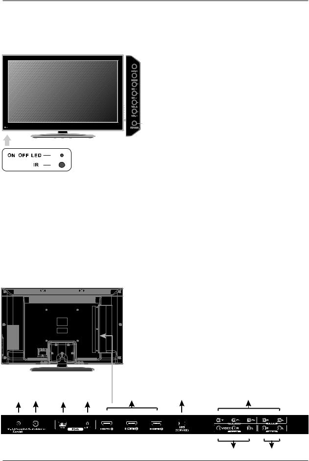
5. FRONT/BACK CONNECTIONS OF LCD TV
Front View
|
|
|
|
1. |
Press“INPUT”to select the input source. |
||||
|
|
1 |
2. |
Press “MENU”to bring up the main menu on |
|||||
|
|
||||||||
|
|
2 |
|
the screen. |
< |
|
|
|
|
|
|
|
|
|
|
||||
|
|
|
3 |
3. |
Press“CH |
”or “CH |
> |
”to scan through channels. |
|
|
|
|
|||||||
|
|
|
|
|
|||||
|
|
4. |
Press“VOL+”or “VOL-”to increase or decrease |
||||||
|
|
|
|
||||||
|
|
|
4 |
|
the volume. |
|
|
|
|
|
|
|
|
|
|
|
|||
|
|
5. |
Press“POWER” button to turn the TV on or off. |
||||||
|
|
||||||||
|
|
|
|
||||||
6. REMOTE SENSOR: infrared sensor for the
5
remote control.
7. POWER INDICATOR: Shows red in standby mode.
Shows blue when your TV is turned on.
7
6
Back View and Control Connections
1.Digital Audio Out (Coaxial): Connects to the coaxial audio input of your digital stereo equipment.
2.Cable/Antenna: RF input that connects to your cable or
VHF/UHF antenna.
3. VGA(PC): Connects to a personal computer's video output connector.
4.PC AUDIO: Connects to a personal computer's audio output connector.
5.HDMI1/HDMI2/HDMI3: HDMI (High-Definition Multimedia Interface) provides an uncompressed, all-digital audio/ video interface between this TV and any HDMI-equipped
A/V equipment. HDMI supports enhanced, or highdefinition video, plus digital audio.
6. USB SERVICE: This USB port is for service only. Output power 5V  0.5A.
0.5A.
7.YPbPr/AUDIO(L/R): Connect the YPbPr /Audio output jack of DVD or VCR.
8.VIDEO/AUDIO(L/R): Connect the Video/Audio output jack of DVD or VCR.
9.L-OUT/R-OUT: Connect to Audio Amplifier device.
1 |
2 |
3 |
4 |
5 |
6 |
7 |
|
|
|
|
|
|
|
|
|
|
|
|
|
|
8 9
7

TV INSTALLATION DRAWINGS
6. TV INSTALLATION DRAWINGS
Power Cord Connection
-Connect the power cord correctly as shown.
-Press the Power of your LCD TV to turn on the LCD TV. The power indicator on the front panel lights up in blue .
Antenna Connection
To ensure good picture and sound, TV antenna system needs to be instalLCD. The antenna system as shown can be sourced from TV equipment shops, which will provide service for correct installation and connection. After installation, insert the 75-ohm antenna plug into the antenna jack as shown.
VHF ANTENNA |
UHF ANTENNA |
OUTDOOR
ANTENNA
AMPLIFIER
INDOOR
ANTENNA
AMPLIFIER
75 OHM
ANTENNA PLUG
POWER PLUG OF
ANTENNA
AMPLIFIER
8

TV INSTALLATION DRAWINGS
AV Connection
Connect the VIDEO and AUDIO output jack of the DVD or VCR to the VIDEO jacks on the set using the RCA cable. Match the jack colors: Video is yellow, Audio left is white, and Audio right is red. Select the AV input source using the SOURCE button on the remote control.
TV Back
Video Cable |
|
|
|
|
AUDIO cable |
|
|
|
|
|
|
|
|
|
|
|
|
|
|
|
|
|
|
|
|
|
|
|
|
|
|
|
|
|
|
|
|
|
|
|
|
|
|
|
|
|
|
|
VIDEO |
R |
L |
DVD or VCR Back
DVD or VCR
YPbPr(Component) Connection
Connect the YPbPr output of the DVD or VCR to the YPbPr input on the set. The picture quality is improved; compared to connecting a regular VCR to the video input. Connect the Audio output of the DVD or VCR to the Audio input jacks on the set using the RCA cable.
Match the jacks colors :Y is green, Pb is blue, Pr is red, Audio left is white and Audio right is red.
Select component input source using the SOURCE button on the remote control.
TV Back
YPbPr cable
AUDIO cable
Y Pb Pr R L
DVD or VCR Back
DVD or VCR
9

TV INSTALLATION DRAWINGS
VGA(PC) Connection
Connect the RGB output of the PC to the VGA(PC) jack on the set. Connect the AUDIO output of the PC to the PC AUDIO jack on the set. Select the RGB input source with using the SOURCE button on the remote control.
TV Back
|
|
|
|
|
|
|
|
|
|
|
|
VGA Cable |
|
|
Audio Cable |
||
|
|
|
|
|
|
|
|
|
|
|
|
|
|
|
|
|
|
|
|
|
|
|
|
|
|
|
|
|
|
|
|
|
|
|
|
|
|
|
|
|
|
|
|
|
|
|
|
RGB-PC OUTPUT AUDIO
COAXIAL Connection
Connect to Audio Amplifier device to the Coaxial output jack on the TV.
TV Back
COAX Cable
COAX
the audio amplifier back
Audio amplifier
10

TV INSTALLATION DRAWINGS
HDMI Connection
HDMI plug which replaces the HDMI connection allows transfer of all audio/video/control
signals through one cable only. These signals are transferred in digital.
TV Back
HDMI Cable
DVD Back
Service Port Function
Service port: (For factory uses only.)
TV Back
USB Cable
Wall Mounting
The TV is provided with mounting holes for a VESA approved wall mounting bracket (NOT SUPPLIED).
Remove the screws holding the base to the base bracket and lift the base away (do not remove the base mounting brackets). Mount the VESA bracket using 4 x M5x12 isometric threaded screws (not supplied).
Do not use screws longer than 20mm; damage will occur to the internal parts.
Caution: Your new TV is heavy; please consult with a professional wallmount installer to perform this installation.
11
 Loading...