

USB Dongleserver
myUTN-80
Quick Installation Guide
MHAB-QI-myUTN80
Version: 5.1 | 2018-11

Overview
This 'Quick Installation Guide' describes the hardware installation and initial
setup of the myUTN-80.
Table of contents
1.
Do you need assistance? Contact us!
Monday to Thursday
Friday
8:00 a.m. to 4:45 p.m. and
8:00 a.m. to 3:15 p.m. (CET)
+49 (0)521 94226-44
support@seh.de
www.seh-technology.com
Überblick
Dieser 'Quick Installation Guide' beschreibt die Hardware-Installation und
Inbetriebnahme des myUTN-80.
Inhaltsverzeichnis
18.
Benötigen Sie Hilfe? Kontaktieren Sie uns!
Montag–Donnerstag
Freitag
8:00–16:45 Uhr
8:00–15:15Uhr
+49 (0)521 94226-44
support@seh.de
www.seh.de

Contents
General Information . . . . . . . . . . . . . . . . . . . . . . . . . . . . . . . . . . . . . . . . . . . . . . . . . .2
Purpose .....................................................................................................................................2
Scope of Supply .....................................................................................................................2
Accessories...............................................................................................................................3
Technical Data.........................................................................................................................4
LED Display ..............................................................................................................................5
Type Plate.................................................................................................................................6
Safety Regulations. . . . . . . . . . . . . . . . . . . . . . . . . . . . . . . . . . . . . . . . . . . . . . . . . . . .7
Hardware Installation . . . . . . . . . . . . . . . . . . . . . . . . . . . . . . . . . . . . . . . . . . . . . . . . .8
Software Installation. . . . . . . . . . . . . . . . . . . . . . . . . . . . . . . . . . . . . . . . . . . . . . . . . .9
Getting Started: SEH UTN Manager . . . . . . . . . . . . . . . . . . . . . . . . . . . . . . . . . . .10
Starting the SEH UTN Manager ......................................................................................11
Assigning an IP Address to the UTN Server................................................................12
Adding the UTN Server to the Selection List.............................................................13
Connecting the USB Dongle to the Client..................................................................14
Configuring the UTN Server . . . . . . . . . . . . . . . . . . . . . . . . . . . . . . . . . . . . . . . . . .15
Locking the UTN Server . . . . . . . . . . . . . . . . . . . . . . . . . . . . . . . . . . . . . . . . . . . . . .16
Regulatory Compliance Information . . . . . . . . . . . . . . . . . . . . . . . . . . . . . . . . . .34
Quick Installation Guide [en] 1
General Information
Purpose
The Dongleserver 'myUTN-80' gives network participants access to USB
dongles. For this purpose, the USB dongles will be connected to the USB ports
of the myUTN-80. The software tool 'SEH UTN Manager' handles the access to
the USB dongles.
The SEH UTN Manager is installed on all clients that are intended to access a USB
dongle in the network. The SEH UTN Manager shows the availability of all UTN
servers in the network and establishes a connection between the client and the
USB port including the connected USB dongle.
The lockable housing cover of the myUTN-80 allows for a central and safe
storage of the USB dongles.
The administration of the myUTN-80 is done via the 'myUTN Control Center'.
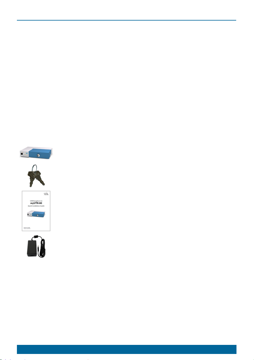
Scope of Supply
Check the package content before getting started:
UTN server Dongleserver 'myUTN-80'
Key For the lock in the dongle server lid
Quick
Installation
Guide
Power pack External power pack
2 [en] Quick Installation Guide
The Quick Installation Guide provides a brief
description of the installation of the myUTN-80.
(This document)
Accessories
Value-adding accessories for your myUTN-80 are optionally available from SEH.
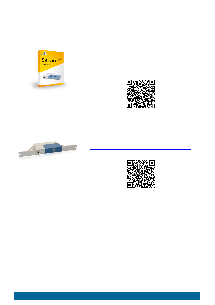
myUTN-80
Service
plus
Package
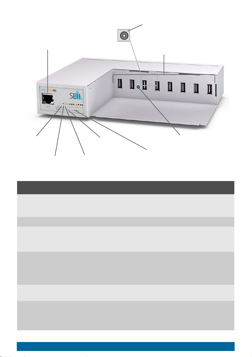
RMK1
(Rack Mount Kit Type 1)
The 'myUTN-80 Service
plus
package' extends the
manufacturer's guarantee of your myUTN-80
from 36 to 60 months. In addition, you will receive
quickly and easily an advance replacement device
in case of a defect!
Detailed information:
http://www.seh-technology.com/services/
service-packages/myutn-80.html
For a perfect and safe storage of your myUTN-80
we recommend the Rack Mount Kit 'RMK1'. Using
the Rack Mount Kit, you can mount the myUTN80 into 19" server racks.
Detailed information:
http://www.seh-technology.com/products/
rack-mount-kits.html
Quick Installation Guide [en] 3
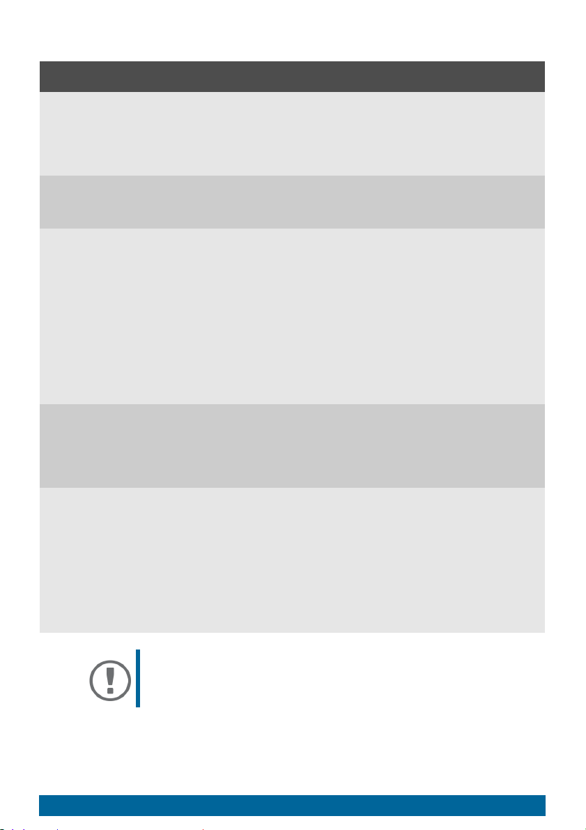
Technical Data
link LED
(green)
activity LED
(yellow)
LED for the USB ports 1–8
(green/orange)
power LED
(yellow)
status LED
(green)
USB ports 1–8
connector for the included
power pack
(at the rear side)
reset button
network connector (RJ-45)
8
1
Properties Values
Network connection
logical:
physical:
Device connection 8 × USB 2.0 Hi-Speed
IEEE 802.3 (10BaseT and 100BaseTX)
1 × RJ-45 (STP, category 5 or better)
Current input • 200 mA at 12 VDC without load
• 2500 mA at 5 VDC
with full load on the USB ports
Power consumption • max. approx. 32 W
with full load on the USB ports
• typ. approx 4.5 W with 8 USB dongles
• typ. approx. 40 kWh/year
Operating environment ambient temperature: 5–40 °C
relative humidity: 20–80 %
Dimensions width: 215 mm
height: 45 mm
depth: 155 mm
weight: 1050 g
4 [en] Quick Installation Guide
LED Display
The LEDs of the UTN server provide information about its status.
LED Action Color Description
Link permanently
green–There is a connection to the network.
on
permanently
off
Activity flashing at
irregular
intervals
Status permanently
off
blinks 3 times
blinks 2 times
Power permanently
on
permanently
off
USB ports
1–8
permanently
off
permanently
on
There is no connection to the
network.
yellow Indicates the exchange of network
data packets.
–
If the activity LED blinks periodically
at the same time, the BIOS mode is
signalized.
green
Indicates the assignment of a
Zeroconf IP address.
green
Indicates the assignment of an IP
address that does not correspond to
0.0.0.0 or that comes from outside
the Zeroconf range.
yellow–The device is powered.
The device is not powered.
–
No USB dongle is connected to the
respective port.
green
A USB dongle is connected to the
respective port.
permanently
on
orange
The connection to the respective
port and the attached USB dongle is
activated.
Important:
During the activation procedure, the behavior of the
LEDs differs from this description.
Quick Installation Guide [en] 5

Type Plate
The type plate gives important product information, such as hardware and
certification information as well as the serial number. The serial number
contains the production date: nnn YYYY MM nnnnn.
This information helps you e.g. during maintenance and is needed for support
requests as well as for the ’myUTN-80 Serviceplus Package’
3.
6 [en] Quick Installation Guide
Safety Regulations
UTN servers are network devices for use in office environments. The myUTN-80
is designed for the integration of USB dongles into TCP/IP networks.
Important:
Before starting the installation and the initial setup
procedure as well during the operation of the UTN
server, note the following safety regulations. Their
purpose is to protect yourself and others from personal
injuries, and to avoid damage to the equipment.
• Read the documentation and make sure that your system meets the requirements listed therein.
• Avoid contact with humidity or liquids.
• The device must only be connected and operated if it is in perfect condition.
• Make sure that no-one steps on or stumbles over the cables.
• If the supplied power cord cannot be used in your country, acquire an appropriate power cord that suits national provisions. For more information, consult your retailer.
• Do not connect a telephone cable to the RJ-45 connector. The RJ-45 connector may only be connected to SELV voltages. For the connection to the RJ-45
connector only STP cabling (category 5 or better) may be used. The shielding
must fit flushly to the connector.
• Do not open the housing. Unauthorized modifications to the device can affect the product certification and are forbidden.
• The device must not be directly connected to outdoor lines.
• The device must only be operated using the power pack included in the
package.
• Only use a certified USB cable (< 3 m) listed at www.usb.org
• Electrostatic discharges (ESD) may impair device performance.
• An interruption of the supply voltage may impair device performance or
cause malfunctions.
.
Quick Installation Guide [en] 7
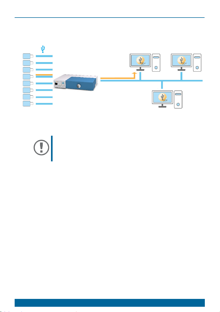
Hardware Installation
USB dongles
myUTN-80
network
clients with software tool
'SEH UTN Manager'
USB 2.0
You can directly connect up to eight USB dongles to the myUTN-80.
1. Connect the USB dongle to a USB port of the UTN server.
Important:
USB dongle and UTN server can be connected via a USB
cable, if required.
Only use USB cables shorter than 3 meters.
2. Repeat step 1 if you want to connect more than one USB dongle.
3. Connect the network cable (RJ-45) to the UTN server.
4. Connect the power cord to the UTN server.
The UTN server boots and then is ready for use.
8 [en] Quick Installation Guide

Software Installation
The software tool 'SEH UTN Manager' organizes the access of the USB dongles.
The SEH UTN Manager is available in two versions:
•Complete version
• Minimal version (only command-line interface)
The complete version has a graphical user interface and offers additional
features. A detailed description can be found in the myUTN User Manual.
The SEH UTN Manager is installed on all clients that are intended to access a USB
dongle in the network. Different installation files are available, depending on
the operating system.
First, you have to download the installation file for the SEH UTN Manager from
the website of SEH Computertechnik GmbH:
http://www.seh-technology.com/services/downloads/
download-dongleserver/myutn-80.html
System requirements:
– Windows 7 or later except for Windows Server 2008
1
OS X respectively macOS 10.9 or later
– The installation can only be carried out by users with administrative rights.
Important:
The SEH UTN Manager is also available for selected
Linux systems.
All information necessary for installing and using the
SEH UTN Manager in Linux environments can be found
in the myUTN User Manual Linux. The documentation is
available via the link given above.
1. Start the installation file.
2. Install the complete version of the SEH UTN Manager (including graphical
user interface). To do so, follow the installation routine.
The SEH UTN Manager is installed on your client.
1. Windows 7 and Windows Server 2008 R2: KB3033929 (https://technet.microsoft.com/en-us/li-
brary/security/3033929) must be installed.
Quick Installation Guide [en] 9

Getting Started: SEH UTN Manager
After the SEH UTN Manager is started, the network will be scanned for
connected UTN servers. The network range to be scanned is freely definable.
All UTN servers found will be shown in the 'network list' together with the
connected USB dongles. The required UTN servers will be selected and added to
the 'selection list'. The UTN servers listed in the selection list and the connected
USB dongles can then be used by the user.
This chapter describes the first steps with the program.
• ’Starting the SEH UTN Manager’
• ’Assigning an IP Address to the UTN Server’
• ’Adding the UTN Server to the Selection List’
• ’Connecting the USB Dongle to the Client’
Detailed information on how to use the SEH UTN Manager can
be found in the Online Help. ITo start the online help, go to the
menu bar and select Help – Online Help.
11
12
13
14
Important:
Client and UTN server communicate via the UTN port
9200. This port must not be blocked by a security
software (firewall). If necessary, you can change the port
number and use a secure UTN SSL port. A detailed
description can be found in the myUTN User Manual.
10 [en] Quick Installation Guide

Starting the SEH UTN Manager
Windows
Start the SEH UTN Manager on your client via the Windows start menu.
All apps SEH Computertechnik GmbH SEH UTN Manager)
(Start
Mac
To start the program, double-click the 'SEH UTN Manager.app' file.
(Applications
SEH UTN Manager.app)
Important:
During the initial configuration, client and UTN server
must be assigned to the same local network segment.
Quick Installation Guide [en] 11

Assigning an IP Address to the UTN Server
Once the UTN server is connected to the network, it checks whether an IP
address can be obtained from the boot protocols BOOTP or DHCP. If this is not
the case, the UTN server assigns itself an IP address via Zeroconf from the
address range reserved for Zeroconf (169.254.0.0/16).
The UTN servers found by the program will be displayed in the network list. You
can change the TCP/IP parameters of the UTN server.
1. Confirm the note dialog Your Selection List seems to be empty with Yes.
If the note dialog is not available and the main dialog appears instead, select Selection List –
Edit in the menu bar.
The Edit Selection List dialog appears.
2. In the network list, select the UTN server.
3. In the shortcut menu, select Set IP Address.
The Set IP Address dialog appears.
4. Enter the relevant TCP/IP parameters.
5. Click OK.
The settings will be saved.
12 [en] Quick Installation Guide

Adding the UTN Server to the Selection List
The selection list displays the UTN servers and the USB dongles connected to
their USB ports.
Define the devices you want to use. To do this, you must add the UTN server
(and the connected USB dongles) shown in the network list to the selection list.
1. In the menu bar, select Selection List – Edit.
The Edit Selection List dialog appears.
2. In the network list, select the UTN server.
3. Click Add.
4. Repeat steps 1 to 3, if necessary.
5. Click OK.
The UTN servers are shown in the selection list.
You can extend the search for UTN servers to any network
range. To do this, change the search parameters for the network scan.
Windows: Via Program – Options.
Mac: Via SEH UTN Manager – Preferences.
Quick Installation Guide [en] 13

Connecting the USB Dongle to the Client
To use a USB dongle, a connection is established between the client and the
USB port of the UTN server to which the USB dongle is connected.
All provisions (driver installation, etc.) necessary to operate the USB dongle
locally (i.e. connected directly to the client) have been met on the client. Ideally, the USB dongle has been connected and operated on the client locally
according to the instructions of the manufacturer.
The USB port is not connected to another client. A USB dongle that was made
available by the UTN server can only be used by one network participant at a
time.
1. In the selection list, select the port.
2. From the menu bar, select Port – Activate.
The connection will be established.
Important:
Deactivate the connection to the USB port when you no
longer need the attached USB dongle. To do this, select
Port – Deactivate from the menu bar.
14 [en] Quick Installation Guide

Configuring the UTN Server
The UTN server can be configured and monitored via the ‘myUTN Control
Center‘. The myUTN Control Center is stored in the UTN server and can be
launched by means of a browser (Microsoft Edge, Firefox, Safari).
1. Open your browser.
2. Enter the IP address of the UTN server as the URL.
The myUTN Control Center appears in the browser.
If the myUTN Control Center is not displayed, check the proxy settings of your browser.
Detailed information about the configuration of the UTN
server can be found in the Online Help of the myUTN Control
Center.
To start the Online Help, click the '?' icon.
Quick Installation Guide [en] 15

Locking the UTN Server
The myUTN-80 has a lockable lid. With it, you can protect the USB dongles.
To close the Dongleserver, insert the two straps of the lid into the notches of the
housing. The key for the lock is delivered with the myUTN-80
2.
16 [en] Quick Installation Guide

Quick Installation Guide [en] 17

Inhaltsverzeichnis
Allgemeine Information . . . . . . . . . . . . . . . . . . . . . . . . . . . . . . . . . . . . . . . . . . . . . .19
Verwendungszweck ...........................................................................................................19
Lieferumfang.........................................................................................................................19
Optionales Zubehör ...........................................................................................................20
Technische Daten ................................................................................................................21
LED-Anzeige..........................................................................................................................22
Typenschild............................................................................................................................23
Sicherheitsvorschriften . . . . . . . . . . . . . . . . . . . . . . . . . . . . . . . . . . . . . . . . . . . . . .24
Hardware-Installation. . . . . . . . . . . . . . . . . . . . . . . . . . . . . . . . . . . . . . . . . . . . . . . .25
Software-Installation . . . . . . . . . . . . . . . . . . . . . . . . . . . . . . . . . . . . . . . . . . . . . . . .26
Erste Schritte mit dem SEH UTN Manager. . . . . . . . . . . . . . . . . . . . . . . . . . . . . .27
SEH UTN Manager starten................................................................................................28
UTN-Server eine IP-Adresse zuweisen.........................................................................29
UTN-Server der Auswahlliste hinzufügen...................................................................30
USB-Dongle mit Client verbinden.................................................................................31
UTN-Server konfigurieren . . . . . . . . . . . . . . . . . . . . . . . . . . . . . . . . . . . . . . . . . . . .32
UTN-Server abschließen. . . . . . . . . . . . . . . . . . . . . . . . . . . . . . . . . . . . . . . . . . . . . .33
Regulatory Compliance Information (Konformitätserklärungen) . . . . . . . .34
18 [de] Quick Installation Guide

Allgemeine Information
Ver wendungszweck
Der Dongleserver 'myUTN-80' stellt den Zugriff auf USB-Dongles mehreren
Netzwerkteilnehmern zur Verfügung. Dazu werden die USB-Dongles an die
USB-Ports des myUTN-80 angeschlossen. Die Zugriffsverteilung der USBDongles erfolgt über das Software-Tool 'SEH UTN Manager'.
Der SEH UTN Manager wird auf allen Clients installiert, die auf einen im
Netzwerk bereitgestellten USB-Dongle zugreifen sollen. Der SEH UTN Manager
zeigt die Verfügbarkeit aller im Netzwerk eingebundenen UTN-Server an und
stellt die Verbindung zwischen Client und USB-Port inklusive dem daran
angeschlossenen USB-Dongle her.
Der abschließbare Gehäusedeckel am myUTN-80 ermöglicht eine zentrale und
sichere Aufbewahrung der USB-Dongles.
Die Verwaltung des myUTN-80 erfolgt über das 'myUTN Control Center'.
Lieferumfang
Überprüfen Sie den Packungsinhalt auf Vollständigkeit, bevor Sie die
Installation beginnen:
UTN-Server Dongleserver 'myUTN-80'
Schlüssel Für das Schloss im Dongleserver-Deckel
Quick
Installation
Guide
Netzteil Externes Netzteil
Quick Installation Guide [de] 19
Der Quick Installation Guide beinhaltet eine kurze
Beschreibung der Installation des myUTN-80.
(Dieses Dokument)

Optionales Zubehör
Als praktische Ergänzung zu Ihrem myUTN-80 bietet SEH optional erhältliches
Zubehör an.
myUTN-80
plus
Service
-Paket
RMK1
(Rack Mount Kit Type 1)
plus
Das 'myUTN-80 Service
-Paket' verlängert die
Herstellergarantie Ihres myUTN-80 von 36 auf 60
Monate. Zudem erhalten Sie im Falle eines
Defektes bequem und schnell ein VorabAustausch-Gerät.
Ausführliche Informationen:
http://www.seh-technology.com/de/
service/service-pakete/myutn-80.html
Für die optimale und sichere Aufbewahrung Ihres
myUTN-80 empfehlen wir den Montagesatz
'RMK1'. Der Montagesatz ermöglicht den Einbau
des myUTN-80 in 19-Zoll-Serverschränke.
Ausführliche Informationen:
http://www.seh-technology.com/de/
produkte/rack-mount-kits.html
20 [de] Quick Installation Guide

Technische Daten
Link-LED
(grün)
Activity-LED
(gelb)
LED für die USB-Ports 1–8
(grün/orange)
Power-LED
(gelb)
Status-LED
(grün)
USB-Ports 1–8
Anschluss für die
Stromversorgung über das
mitgelieferte Netzteil
(auf der Rückseite)
Reset-Taster
Netzwerkanschluss (RJ-45)
8
1
Eigenschaften Wer te
Netzwerkanschluss
Logisch:
Physisch:
IEEE 802.3 (10BaseT und 100BaseTX)
1 × RJ-45 (STP, Kategorie 5 oder besser)
Geräteanschluss 8 × USB 2.0 Hi-Speed
Stromaufnahme • 200 mA bei 12 V Gleichspannung ohne Last
• 2500 mA bei 12 V Gleichspannung
bei Volllast auf den USB-Ports
Leistungsaufnahme • max. ca. 32 W bei Volllast auf den USB-Ports
• typ. ca. 4,5 W mit 8 USB-Dongles
• typ. ca. 40 kWh/Jahr
Betriebsumgebung Umgebungstemperatur: 5–40 °C
Relative Luftfeuchtigkeit: 20–80 %
Abmessungen Breite: 215 mm
Höhe: 45 mm
Tiefe: 155 mm
Gewicht: 1050 g
Quick Installation Guide [de] 21

LED-Anzeige
Durch die Interpretation des LED-Leuchtverhaltens kann der Zustand des UTNServers ermittelt werden.
LED Aktion Farbe Beschreibung
Link Dauer-An
grün
Eine Verbindung zum Netzwerk ist
vorhanden.
Dauer-Aus
Activity unregel-
mäßiges
Blinken
Status Dauer-Aus
3 x Blinken
2 x Blinken
Power Dauer-An
Dauer-Aus
USB-Port 1–8 Dauer-Aus
Dauer-An
–
Es besteht keine Verbindung zum
Netzwerk.
gelb Signalisiert den Austausch von
Netzwerk-Datenpaketen.
–
Bei gleichzeitigem zyklischen Blinken
der Activity-LED wird der BIOSModus signalisiert.
grün
Signalisiert die Vergabe einer
Zeroconf-IP-Adresse.
grün
Signalisiert die Vergabe einer IPAdresse, die nicht 0.0.0.0 entspricht
oder aus dem Bereich Zeroconf
kommt.
gelb
–
Das Gerät wird mit Strom versorgt.
Das Gerät wird nicht mit Strom
versorgt.
–
Es ist kein USB-Dongle am
betreffenden Port angeschlossen.
grün
Es ist ein USB-Dongle am
betreffenden Port angeschlossen.
Dauer-An
orange
Die Verbindung zum betreffenden
Port und dem daran
angeschlossenen USB-Dongle ist
aktiviert.
Wichtig:
Während des Einschaltvorgangs weicht das LEDLeuchtverhalten von der Beschreibung ab.
22 [de] Quick Installation Guide

Typ ens chi ld
Auf dem Typenschild finden Sie wichtige Angaben zu Ihrem Produkt, wie z.B.
Informationen zur Hardware und zu Zertifizierungen sowie die Seriennummer.
Die Seriennummer enthält das Produktionsdatum: nnn YYYY MM nnnnn.
Diese Angaben helfen Ihnen z.B. bei der Wartung und Sie benötigen sie für
Support-Anfragen sowie für das ’myUTN-80 Serviceplus-Paket’
20.
Quick Installation Guide [de] 23

Sicherheitsvorschriften
UTN-Server sind Netzwerkgeräte für den Gebrauch in Büroumgebungen. Der
myUTN-80 dient dem Einbinden von USB-Dongles in TCP/IP-Netzwerken.
Wichtig:
Beachten Sie vor Inbetriebnahme und beim Betrieb des
UTN-Servers die folgenden Sicherheitsvorschriften, um
sich und andere vor Personenschäden zu schützen
sowie Beschädigungen am Gerät zu vermeiden.
• Lesen Sie die Dokumentation und stellen Sie sicher, dass Ihr System den aufgeführten Anforderungen entspricht.
• Das Gerät darf nicht mit Feuchtigkeit oder Flüssigkeit in Berührung kommen.
• Das Gerät darf nur in unversehrtem Zustand angeschlossen und betrieben
werden.
• Verlegen Sie alle Kabel so, dass niemand darauf treten oder darüber stolpern
kann.
• Falls das beiliegende Netzkabel für Ihr Land nicht einsetzbar ist, beschaffen
Sie ein passendes Netzkabel mit der jeweiligen nationalen Zulassung. Fragen
Sie hierzu Ihren Fachhändler.
• Schließen Sie keine Telefonleitungen an den RJ-45-Stecker an. An diesen darf
nur Sicherheitskleinspannung angeschlossen werden. Verwenden Sie für
den Anschluss an den RJ-45-Stecker nur STP-Kabel (Kategorie 5 oder besser).
Kabelschirm und Steckerschirm des Kabels müssen flächig verbunden sein.
• Öffnen Sie nicht das Gehäuse. Eigenmächtige konstruktive Veränderungen
am Gerät können die Produktzertifizierung beeinträchtigen und sind verboten.
• Das Gerät darf nicht direkt an Leitungen die im Freien verlegt sind (outdoor)
angeschlossen werden.
• Das Gerät darf nur mit dem mitgelieferten Netzteil betrieben werden.
• Verwenden Sie als USB-Kabel ein zertifiziertes USB-Kabel (< 3 m), das unter
www.usb.org
• Elektrostatische Entladungen (ESD) können die Geräteleistung beeinträchtigen.
• Eine Unterbrechung der Versorgungsspannung kann die Geräteleistung beeinträchtigen oder Fehlfunktionen verursachen.
gelistet ist.
24 [de] Quick Installation Guide

Hardware-Installation
USB-Dongles
myUTN-80
Netzwerk
Clients mit Software-Tool
'SEH UTN Manager'
USB 2.0
Am myUTN-80 können bis zu acht USB-Dongles direkt angeschlossen werden.
1. Stecken Sie den USB-Dongle an einen USB-Port des UTN-Servers.
Wichtig:
Bei Bedarf können USB-Dongle und UTN-Server via USBKabel verbunden werden.
Verwenden Sie hierzu ausschließlich USB-Kabel mit
Längen unter 3 Metern.
2. Wiederholen Sie Schritt 1 je nach Anzahl der anzuschließenden USBDongles.)
3. Verbinden Sie das Netzwerkkabel (RJ-45) mit dem UTN-Server.
4. Verbinden Sie das Netzkabel mit dem UTN-Server.
Der UTN-Server startet und ist anschließend betriebsbereit.
Quick Installation Guide [de] 25

Software-Installation
Die Zugriffsverteilung der USB-Dongles wird über das Software-Tool SEH UTN
Manager organisiert. Der SEH UTN Manager ist in zwei Varianten verfügbar:
• Vollständige Variante
• Minimal-Variante (reine Kommandozeilen-Version)
Die vollständige Variante verfügt über eine grafische Bedienoberfläche und
bietet zusätzliche Funktionen. Detaillierte Beschreibungen finden Sie in der
myUTN-Benutzerdokumentation.
Der SEH UTN Manager wird auf allen Clients installiert, die auf einen im
Netzwerk bereitgestellten USB-Dongle zugreifen sollen. Je nach Betriebssystem
sind verschiedene Installationsdateien verfügbar.
Laden Sie zuerst die Installationsdatei für den SEH UTN Manager von der SEH
Computertechnik GmbH-Homepage:
http://www.seh-technology.com/de/service/
downloads/download-dongleserver/myutn-80.html
Systemvoraussetzungen:
– Windows 7 oder höher außer Windows Server 20081;
OS X bzw. macOS 10.9 oder höher
– Die Installation kann ausschließlich durch Benutzer mit administrativen
Rechten durchgeführt werden.
Wichtig:
Der SEH UTN Manager ist auch für ausgewählte LinuxSysteme verfügbar.
Alle Informationen für die Installation und den Einsatz in
Linux-Umgebungen finden Sie in der myUTNBenutzerdokumentation Linux. Die Dokumentation
finden Sie unter dem oben angegebenen Link.
1. Starten Sie die Installationsdatei.
2. Installieren Sie die vollständige Version des SEH UTN Managers (inkl. grafischer Benutzeroberfläche). Folgen Sie hierzu der Installationsroutine.
Der SEH UTN Manager ist auf Ihrem Client installiert
1. Windows 7 und Windows Server 2008 R2: KB3033929 (https://technet.microsoft.com/en-us/li-
brary/security/3033929) muss installiert sein.
26 [de] Quick Installation Guide

Erste Schritte mit dem SEH UTN Manager
Nach dem Start des SEH UTN Managers wird das Netzwerk nach
angeschlossenen UTN-Servern gescannt. Der zu scannende Netzwerkbereich ist
frei definierbar.
Nach dem Scannen des Netzwerks werden alle gefundenen UTN-Server und
deren angeschlossene USB-Dongles in der 'Netzwerkliste' angezeigt. Die
benötigten UTN-Server werden ausgewählt und der 'Auswahlliste' hinzugefügt.
Die in der Auswahlliste aufgeführten UTN-Server und die daran
angeschlossenen USB-Dongles können dann vom Benutzer verwendet werden.
Dieses Kapitel informiert über die ersten Handlungsschritte mit dem Programm.
•’SEH UTN Manager starten’
• ’UTN-Server eine IP-Adresse zuweisen’
• ’UTN-Server der Auswahlliste hinzufügen’
• ’USB-Dongle mit Client verbinden’
Detaillierte Informationen zur Bedienung des SEH UTN
Managers entnehmen Sie der Online Hilfe. Um die Online Hilfe
zu starten, wählen Sie im Menü Hilfe den Befehl Online Hilfe.
28
29
30
31
Wichtig:
Client und UTN-Server kommunizieren über den UTNPort 9200. Dieser Port darf nicht durch eine
Sicherheitssoftware (Firewall) blockiert werden. Bei
Bedarf kann die Portnummer geändert und ein sicherer
UTN-SSL-Port verwendet werden. Detaillierte
Beschreibungen finden Sie in der myUTNBenutzerdokumentation.
Quick Installation Guide [de] 27

SEH UTN Manager starten
Windows
Starten Sie auf Ihrem Client den SEH UTN Manager über das Windows-
Startmenü.
(Start Alle Apps SEH Computertechnik GmbH SEH UTN Manager)
Mac
Zum Starten des Programms doppelklicken Sie auf die Datei 'SEH UTN
Manager.app'.
(Programme SEH UTN Manager.app)
Wichtig:
Während der Erstkonfiguration müssen Client und UTNServer demselben lokalen Netzwerksegment
zugeordnet sein.
28 [de] Quick Installation Guide

UTN-Server eine IP-Adresse zuweisen
Nachdem der UTN-Server an das Netzwerk angeschlossen ist, überprüft der
UTN-Server, ob er eine IP-Adresse über die Bootprotokolle BOOTP oder DHCP
erhält. Ist das nicht der Fall, gibt sich der UTN-Server über Zeroconf selbst eine
IP-Adresse aus dem für Zeroconf reservierten Adressbereich (169.254.0.0/16).
Die vom Programm gefundenen UTN-Server werden in der Netzwerkliste
angezeigt. Sie haben die Möglichkeit, die TCP/IP-Parameter am UTN-Server zu
ändern.
1. Bestätigen Sie den Hinweisdialog Auswahlliste ist leer mit Ja.
Falls kein Hinweisdialog vorhanden ist und der Hauptdialog angezeigt wird, wählen Sie im
Menü Auswahlliste den Befehl Bearbeiten.
Der Dialog Auswahlliste bearbeiten erscheint.
2. Markieren Sie den UTN-Server in der Netzwerkliste.
3. Wählen Sie im Kontextmenü IP-Adresse definieren.
Der Dialog IP-Adresse definieren erscheint.
4. Geben Sie die entsprechenden TCP/IP-Parameter ein.
5. Wählen Sie die Schaltfläche OK an.
Die Einstellungen werden gespeichert.
Quick Installation Guide [de] 29

UTN-Server der Auswahlliste hinzufügen
Die Auswahlliste zeigt die UTN-Server und die an ihre USB-Ports
angeschlossenen USB-Dongles an.
Definieren Sie die Geräte, die Sie nutzen möchten. Fügen Sie hierzu den in der
Netzwerkliste angezeigten UTN-Server mitsamt seinen angeschlossenen USBDongles der Auswahlliste hinzu.
1. Wählen Sie im Menü Auswahlliste den Befehl Bearbeiten.
Der Dialog Auswahlliste bearbeiten erscheint.
2. Markieren Sie den UTN-Server in der Netzwerkliste.
3. Wählen Sie die Schaltfläche Hinzufügen an.
4. Wiederholen Sie die Schritte 2–3 nach Bedarf.
5. Wählen Sie die Schaltfläche OK an.
Die UTN-Server werden in der Auswahlliste angezeigt.
Die Suche nach UTN-Servern kann auf beliebige Netzwerkbereiche erweitert werden. Ändern Sie hierzu die Suchparameter
für den Netzwerkscan.
Windows: Im Menü Programm über den Dialog Optionen.
Mac: Im Menü SEH UTN Manager über den Dialog Einstellun-
gen.
30 [de] Quick Installation Guide

USB-Dongle mit Client verbinden
Um einen USB-Dongle zu nutzen, wird eine Verbindung zwischen dem Client
und dem USB-Port des UTN-Servers hergestellt, an den der USB-Dongle
angeschlossen ist.
Auf dem Client sind alle Vorbereitungen (Treiberinstallation usw.) getroffen
worden, die notwendig wären, um den USB-Dongle lokal (also direkt an dem
Client angeschlossen) zu betreiben. Idealerweise ist der USB-Dongle zuvor
lokal am Client nach der Anleitung des Herstellers angeschlossen und betrieben worden.
Der USB-Port ist nicht bereits mit einem anderen Client verbunden. Ein über
den UTN-Server zur Verfügung gestellter USB-Dongle kann zeitgleich nur
von einem Netzwerkteilnehmer genutzt werden.
1. Markieren Sie in der Auswahlliste den Port.
2. Wählen Sie im Menü Port den Befehl Aktivieren.
Die Verbindung wird hergestellt.
Wichtig:
Deaktivieren Sie die Verbindung zum USB-Port, sobald
Sie den angeschlossenen USB-Dongle nicht mehr
benötigen. Wählen Sie hierzu im Menü Port den Befehl
Deaktivieren.
Quick Installation Guide [de] 31

UTN-Server konfigurieren
Über das myUTN Control Center kann der UTN-Server konfiguriert und
überwacht werden. Das myUTN Control Center ist in dem UTN-Server
gespeichert und kann mit einem Internet-Browser (Microsoft Edge, Firefox,
Safari) aufgerufen werden.
1. Öffnen Sie Ihren Browser.
2. Geben Sie als URL die IP-Adresse des UTN-Servers ein.
Das myUTN Control Center wird im Browser dargestellt.
Falls das myUTN Control Center nicht angezeigt wird, überprüfen Sie die Proxy-Einstellungen
Ihres Browsers.
Detaillierte Informationen zur Konfiguration des UTN-Servers
entnehmen Sie der Online Hilfe des myUTN Control Centers.
Um die Online Hilfe zu starten, wählen Sie das '?' Symbol an.
32 [de] Quick Installation Guide

UTN-Server abschließen
Der myUTN-80 hat einen abschließbaren Gehäusedeckel. Damit können Sie die
USB-Dongles schützen.
Zum Schließen führen Sie die beiden Laschen des Gehäusedeckels in die Nuten
des Gehäuses ein. Der Schlüssel für das Schloss liegt dem Lieferumfang des
myUTN-80 bei
19.
Quick Installation Guide [de] 33

Regulatory Compliance Information
Important:
The latest version of the EC declaration of conformity
can be downloaded from the website of SEH
Computertechnik GmbH:
http://www.seh-technology.com/services/
ce-notifications.html


Manufacturer:
SEH Computertechnik GmbH
Suedring 11
33647 Bielefeld, Germany
Phone: +49 (0)521 94226-29
Fax: +49 (0)521 94226-99
Support: +49 (0)521 94226-44
Email: info@seh.de
Web: http://www.seh.de
Important Internet Resources:
Support Contacts and Information:
http://www.seh-technology.com/services/support.html
Sales Contacts and Information:
http://www.seh-technology.com/company/
management-and-staff/seh-sales-team.html
Downloads:
http://www.seh-technology.com/services/downloads.html
© 2018 SEH Computertechnik GmbH
All trademarks, registered trademarks, logos and product names are property of
their respective owners.
The contents of this document are subject to change without notification.
This product uses 'Open Source Software'. For further information, go to http://
www.seh.de.
The product documentation gives you valuable information about your
product. Keep the documentation for further reference during the life cycle of
the product.
 Loading...