


USB Deviceservers & USB Dongleservers
myUTN User Manual
Windows
USB Deviceservers
myUTN-50a, myUTN-55, myUTN-2500
USB Dongleservers
myUTN-80, myUTN-800

Manufacturer & Contact
SEH Computertechnik GmbH
Suedring 11
33647 Bielefeld
Germany
Phone: +49 (0)521 94226-29
Fax: +49 (0)521 94226-99
Support: +49 (0)521 94226-44
Email: info@seh.de
Web: http://www.seh-technology.com
Document
Type: User Manual
Title: myUTN User Manual Windows
Version: 4.0 | 2018-06
Legal Information
SEH Computertechnik GmbH has endeavored to ensure that the information in this documentation is correct. If
you detect any inaccuracies please inform us at the address indicated above. SEH Computertechnik GmbH will not
accept any liability for any error or omission. The information in this manual is subject to change without notification.
The original manual is the German version of this document and shall govern. All non-German versions of this
document are translation of the original manual.
All rights are reserved. Copying, other reproduction, or translation without the prior written consent from SEH
Computertechnik GmbH is prohibited.
© 2018 SEH Computertechnik GmbH
All trademarks, registered trademarks, logos and product names are property of their respective owners.

myUTN User Manual Windows
1 General Information........................................................................................ 1
1.1 Product ..............................................................................................................................................................................................1
1.2 Documentation ..............................................................................................................................................................................3
1.3 Support and Service......................................................................................................................................................................4
1.4 Your Safety .......................................................................................................................................................................................4
1.5 First Steps .........................................................................................................................................................................................5
2 Administration Methods................................................................................. 6
2.1 Administration via myUTN Control Center ..........................................................................................................................6
2.2 Administration via the SEH UTN Manager............................................................................................................................8
2.3 Administration via InterCon-NetTool..................................................................................................................................13
2.4 Administration via Email .......................................................................................................................................................... 15
3 Network Settings ........................................................................................... 17
3.1 How to Configure IPv4 Parameters......................................................................................................................................18
3.2 How to Configure IPv6 Parameters......................................................................................................................................20
3.3 How to Configure WLAN..........................................................................................................................................................21
3.4 How to Configure the DNS......................................................................................................................................................23
3.5 How to Configure SNMP ..........................................................................................................................................................23
3.6 How to Configure Bonjour ......................................................................................................................................................24
3.7 How to Configure Email (POP3 and SMTP)........................................................................................................................ 25
3.8 How to Use the UTN Server in VLAN Environments (only myUTN-80 and later).................................................27
4 Device Settings .............................................................................................. 29
4.1 How to Configure the Device Time......................................................................................................................................29
4.2 How to Assign a Description................................................................................................................................................... 29
4.3 How to Assign a Name to a USB Port................................................................................................................................... 30
4.4 How to Disable a USB Port (only myUTN-80 and later)................................................................................................. 30
4.5 How to Configure the UTN (SSL) Port.................................................................................................................................. 31
4.6 How to Get Messages (only myUTN-80 and later)..........................................................................................................31
4.7 How to Configure Acoustic Signals (myUTN-800 only) ................................................................................................32
4.8 How Do I Determine What is Shown in the Display? (myUTN-800 only)................................................................ 33
5 Working with the SEH UTN Manager ........................................................... 35
5.1 How to Find UTN Servers/USB Devices in the Network................................................................................................35
5.2 How to Establish a Connection to a USB Device .............................................................................................................37
5.3 How to Cut the Connection between the USB Device and the Client ....................................................................38
5.4 How to Request an Occupied USB Device.........................................................................................................................38
5.5 How to Automate USB Device Connections and Program Starts .............................................................................39
5.6 How to Find Status Information on USB Ports and USB Devices............................................................................... 42
5.7 How to Use the Selection List and Manage User Access Rights with It................................................................... 42
5.8 How to Use the SEH UTN Manager without Graphical User Interface (utnm)......................................................45
6 Security........................................................................................................... 49
6.1 How to Encrypt the USB Connection................................................................................................................................... 49
6.2 How to Encrypt the Connection to the myUTN Control Center ................................................................................ 51
6.3 How to Define the Encryption Strength for SSL/TLS Connections...........................................................................51
6.4 How to Protect Access to the myUTN Control Center (User Accounts)..................................................................53
6.5 How to Block Ports of the UTN Server (TCP Port Access Control) .............................................................................54
6.6 How to Control Access to USB Devices (only myUTN-80 and later).........................................................................55
6.7 How to Block USB Device Types............................................................................................................................................56

myUTN User Manual Windows
6.8 How to Use Certificates ............................................................................................................................................................56
6.9 How to Configure Network Authentication (IEEE 802.1X)...........................................................................................60
7 Maintenance .................................................................................................. 63
7.1 How to Restart the UTN Server ..............................................................................................................................................64
7.2 How to Update.............................................................................................................................................................................64
7.3 How to Backup Your Configuration .....................................................................................................................................65
7.4 How to Reset Parameters to their Default Values...........................................................................................................66
8 Appendix ........................................................................................................ 68
8.1 Glossary .......................................................................................................................................................................................... 69
8.2 Troubleshooting .........................................................................................................................................................................70
8.3 Parameter Lists ............................................................................................................................................................................73
8.4 SEH UTN Manager – Feature Overview............................................................................................................................... 97
8.1 Index................................................................................................................................................................................................99
myUTN User Manual Windows General Information
1 General Information
• Product 1
• Documentation 3
• Support and Service 4
• Your Safety 4
• First Steps 5
1.1 Product
Purpose
UTN servers comprise USB Deviceservers and USB Dongleservers. As USB Deviceservers they make non-networkready USB devices (e.g. USB hard disk drives, USB printers, etc.) and as USB Dongleservers non-network-ready USB
dongles accessible via TCP/IP network. For this purpose, the USB devices respectively USB dongles will be connected to the USB ports of the UTN server. Then the UTN (UTN = USB to Network) functionality and the corresponding software tool 'SEH UTN Manager' establish a virtual USB connection between USB device respectively
USB dongle and client. The USB device respectively USB dongle can be used as if it were connected locally.
Important:
The Dongleservers myUTN-80 and myUTN-800 are exclusively designed for the deployment of USB dongles.
Important:
Hereinafter USB dongles and USB devices are referred to as 'USB devices'.
System Requirements
The UTN server has been designed for the use in TCP/IP networks.
The SEH UTN Manager runs on the following systems:
• Windows XP or later except for Windows Vista and Windows Server 2008
(For Windows 7 and Windows Server 2008 R2 KB3033929 http://technet.microsoft.com/en-us/library/security/3033929 must be installed.)
• OS X 10.8.x, OS X 10.9.x, OS X 10.10.x, OS X 10.11.2 and later, macOS 10.12.x and later
(OS X 10.11.2 and later: operating system induced limited USB device support. macOS 10.12.x and later: operating system induced limited USB device support.)
• Linux: *.deb (for Debian-based systems) and *.rpm (for Red Hat-based systems) installation packages are available for 64-bit systems. A successful installation cannot be guaranteed due to the multitude of Linux varieties!
The installation must be carried out on your own.
In the following 64-bit systems the installation was tested successfully:
Debian: Debian 8.10, Debian 9, Ubuntu 14.04, Ubuntu 16.04
Red Hat: CentOS 6.9, CentOS 7.4, Fedora 25, Fedora 26, openSUSE Leap 42.3, Oracle 6.9, Oracle 7.4, Red Hat
Enterprise Linux 7.4, SUSE Linux Enterprise 12.3
• IPv4 TCP/IP network
1
myUTN User Manual Windows General Information
Important:
The support of isochronous USB devices (e.g. cameras, microphones, speakers, etc.)
depends on
• the operating system:
- Windows
- Linux
• the UTN server model
(information can be found in the respective product information)
• the software version:
- firmware/software for UTN servers: 14.5.5 or later
- SEH UTN Manager: 3.1.4 or later
This document describes the usage in Windows environments. Information about the usage in other environments can be found in the relevant system-specific User Manual. More details can be found in chapter ’Documentation’ 3.
Combination with Associated Products
You can combine the UTN server with additional SEH Computertechnik GmbH products to ideally adapt the use
of your devices to your environment!
Service
For the Dongleservers myUTN-80 and myUTN-800 service contracts, the Service
Service
you will receive quickly and easily an advance replacement device in case of a defect. Service
plus
plus
packages, are available. The
plus
package extends the manufacturer's guarantee of a Dongleserver from 36 to 60 months. In addition,
plus
packages must
be purchased separately.
Detailed information:
https://www.seh-technology.com/services/service-packages.html
Rack Mount Kits
For a perfect and safe storage of your Dongleserver we recommend the 'Rack Mount Kits' (RMK). With the installation kits, you can install the Dongleservers in 19" server racks.
Detailed information:
https://www.seh-technology.com/products/rack-mount-kits.html
2
myUTN User Manual Windows General Information
1.2 Documentation
Please load all current documents from our Website:
http://www.seh-technology.com
Further applicable documents
Thee UTN documentation consists of the following documents:
Quick Installation Guide Print, PDF Information on safety, technical data, instructions for
hardware installation and initial setup, and declarations
of conformity.
User Manual PDF Detailed description of the UTN server configuration and
administration. System-specific instructions for the following systems:
- Windows
- OS X/macOS
- Linux
Online help HTML Information on how to use the web interface 'myUTN
Control Center'.
(Embedded into web interface; no download.)
Product information Print, PDF Features and technical data
Brochures Print, PDF
Open source licenses online
http://www.seh-technology.com/services/licenses.html
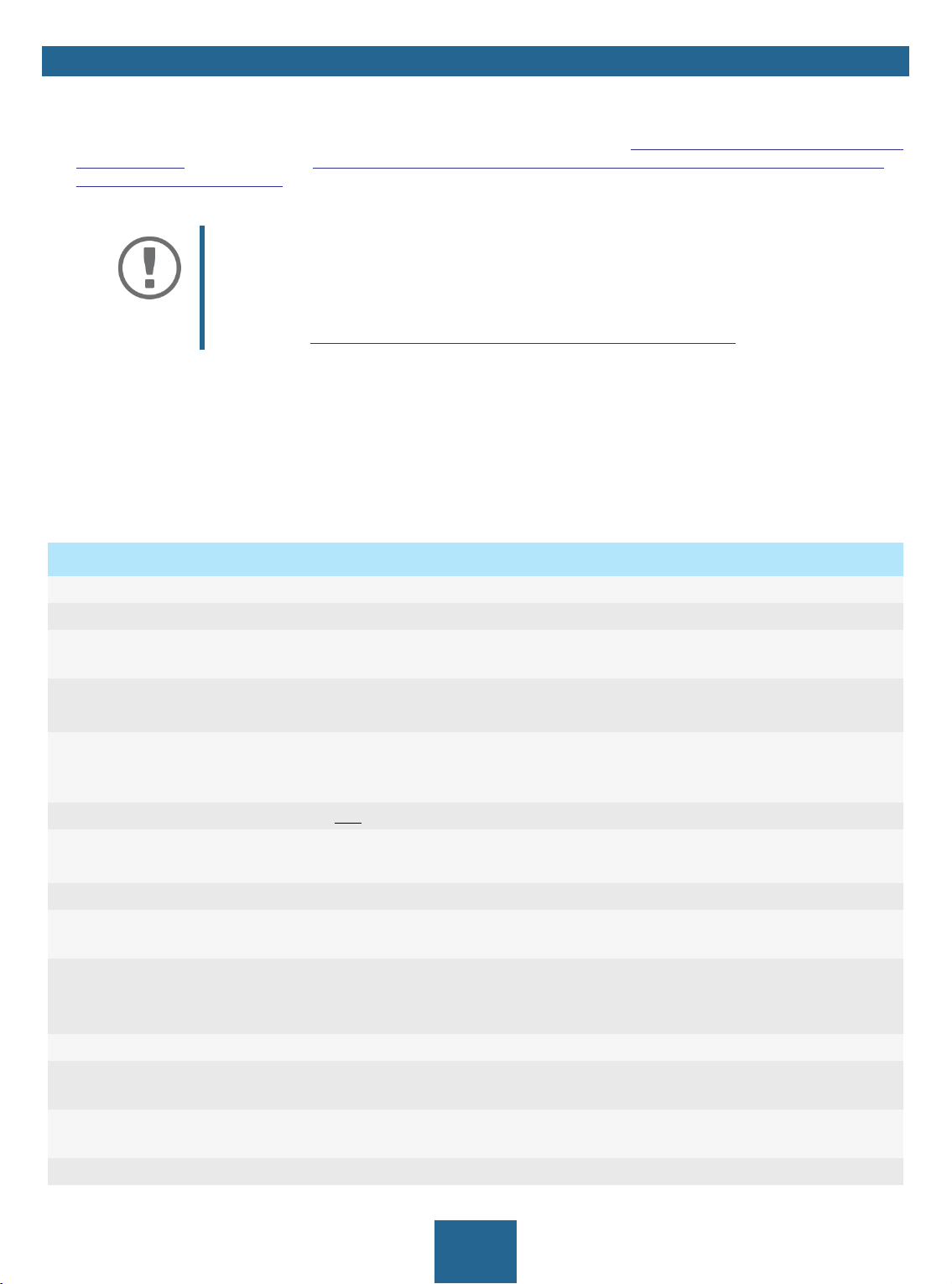
Symbols and Legend
A variety of symbols and mark-ups are used within this document.
WARNING
Warning
Important:
Important information
Requirement Requirements that must be met before you can begin the action.
• Numeration Listing
1. Numeration Step-by-step instructions
Result Outcome of a performed action
Tip
Bold Established terms (e.g. of buttons, menu items, or selection lists)
Courier
'Proper names' Single quotation marks identify proper names
A warning contains important information that must be heeded. Nonobservance may lead to malfunctions.
These notes contain crucial information for failure-free operation.
Recommendations and beneficial advice
Reference (Within the document you can use hyperlinks.)
Code (e.g. for command lines or scripts), Paths
3
myUTN User Manual Windows General Information
1.3 Support and Service
SEH Computertechnik GmbH offers extensive Support. If you have any questions, please contact us.
Monday through Thursday
Friday
+49 (0)521 94226-44
support@seh.de
All information and downloads regarding your product is available on our website:
http://www.seh-technology.com
8:00 a.m. to 4:45 p.m.
8:00 a.m. to 15:15 p.m.
1.4 Your Safety
Read and observe all safety regulations and warnings found in the documentation, on the device and on the packaging. This will avoid potential misuse and prevent damages to people and devices.
Intended Use
The UTN server is used in TCP/IP networks and has been designed for use in office environments. It allows network
users to access non-network-ready USB devices.
Improper Use
All uses of the device that do not comply with the functionalities described in the myUTN documentation are regarded as improper uses.
Safety Regulations
Before starting the initial setup of the UTN server, read and observe the safety regulations in the 'Quick Installation
Guide'. This document is enclosed in the packaging in printed form.
Warnings
Read and observe all warnings mentioned in this document. Warnings are found before any instructions known
to be dangerous. They are presented as follows:
WARNING
Warning!
Liability and Guarantee
SEH Computertechnik GmbH will not accept any liability for personal injuries, property damages and consequential damages resulting from the non-observance of the mentioned safety regulations and warnings. Non-observance will also result in any guarantee claims becoming void.
4
myUTN User Manual Windows General Information
Modifications to the Device and Repairs
It is not allowed to make modifications to the hardware and software or to try to repair the device. If your device
needs to be repaired, contact our support 4.
1.5 First Steps
1. Read and observe the security regulations in order to avoid damages to people and devices 4.
2. Install the hardware. The hardware installation includes connecting the UTN server to the network, USB devic-
es, and power grid ‘ ‘Quick Installation Guide‘.
3. Install the software. The software installation includes installing the required software tool 'SEH UTN Manager'
on your client and assigning an IP address ‘ ‘Quick Installation Guide‘.
4. Configure the UTN server so that it is optimally embedded it into your network and sufficiently protected. All
information on how to do this you will find in this document.
5. Use the SEH UTN Manager to establish and manage connections to the USB devices which are connected to
the UTN server 35.
You can find information on the UTN documentation in chapter
’Documentation’ 3.
5
myUTN User Manual Windows Administration Methods
2 Administration Methods
You can administer, configure and maintain the UTN server in a number of ways:
• Administration via myUTN Control Center 6
• Administration via the SEH UTN Manager 8
• Administration via InterCon-NetTool 13
• Administration via Email 15
2.1 Administration via myUTN Control Center
The UTN server has a user interface, the myUTN Control Center which can be opened in an Internet browser (e.g.
Microsoft Edge).
The UTN server can be configured, monitored and maintained via the myUTN Control Center.
• Open myUTN Control Center in Browser 6
• myUTN Open Control Center via SEH UTN Manager 6
• myUTN Open Control Center via InterCon-NetTool 6
• Controls 7
Open myUTN Control Center in Browser
The UTN server is connected to the network and the power grid.
The UTN server has a valid IP address 18.
1. Open your browser.
2. Enter the IP address of the UTN server as the URL.
The myUTN Control Center is displayed in the browser.
Important:
If the myUTN Control Center is not displayed, check if a gateway is configured (
18) and the proxy settings of your browser.
myUTN Open Control Center via SEH UTN Manager
The UTN server is connected to the network and the power grid.
The UTN server has a valid IP address 18.
The SEH UTN Manager is installed on the client 8.
1. Start the SEH UTN Manager.
2. In the selection list, select the UTN server.
3. In the menu bar, select UTN Server – Configure.
Your browser opens and the myUTN Control Center is displayed.
myUTN Open Control Center via InterCon-NetTool
1. Start the InterCon-NetTool.
2. In the device list, select the UTN server.
3. In the menu bar, select Actions – Launch Browser.
Your browser opens and the myUTN Control Center is displayed.
6
myUTN User Manual Windows Administration Methods
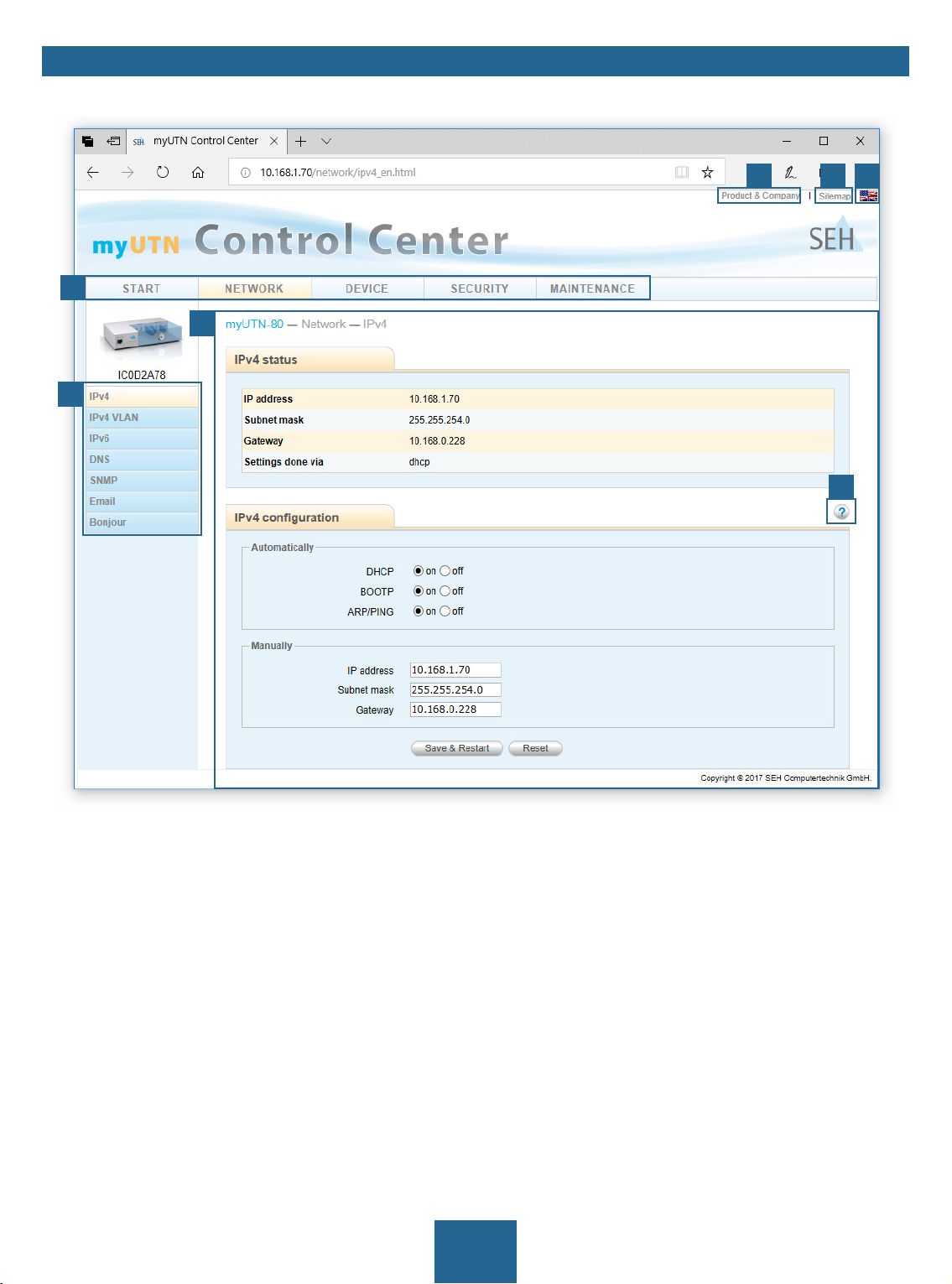
Controls
54 6
1
3
2
7
Figure 1: myUTN Control Center
1 Menu item After selecting a menu item (simple mouse click), the available submenu
items are displayed to the left.
2 Submenu items After selecting a submenu item, the corresponding page with its content
is displayed.
3 Page Menu content
4 Product & Company Manufacturer’s contact details and additional product information.
5 Sitemap Overview of and direct access to all pages of the myUTN Control Center.
6 Flags Language selection
7 ? icon Online help
7
myUTN User Manual Windows Administration Methods
2.2 Administration via the SEH UTN Manager
The 'SEH UTN Manager' is a software tool developed by SEH Computertechnik GmbH. The SEH UTN Manager is
used to establish and manage connections to the USB devices connected to the UTN servers.
• Features 8
• Versions 9
• Installation 10
• Program Start 12
Features
The software is installed on all clients that are meant to access a USB device in the network. After the SEH UTN
Manager is started, the network is scanned for connected UTN servers. All UTN servers found and their connected
USB devices are displayed in the 'network list'. To use the USB devices connected to the UTN server, you have to
add the UTN server to the 'selection list'. The devices shown in the selection list can be administrated and the connected USB devices can be used. Working working with the SEH UTN Manager is described in detail in the chapter
’Working with the SEH UTN Manager’ 35.
WARNING
UTN ( 1) and the corresponding SEH UTN Manager only work in IPv4 networks.
In IPv6-only networks only the myUTN Control Center ( 6) can be accessed to
administrate the UTN server.
1
3
4
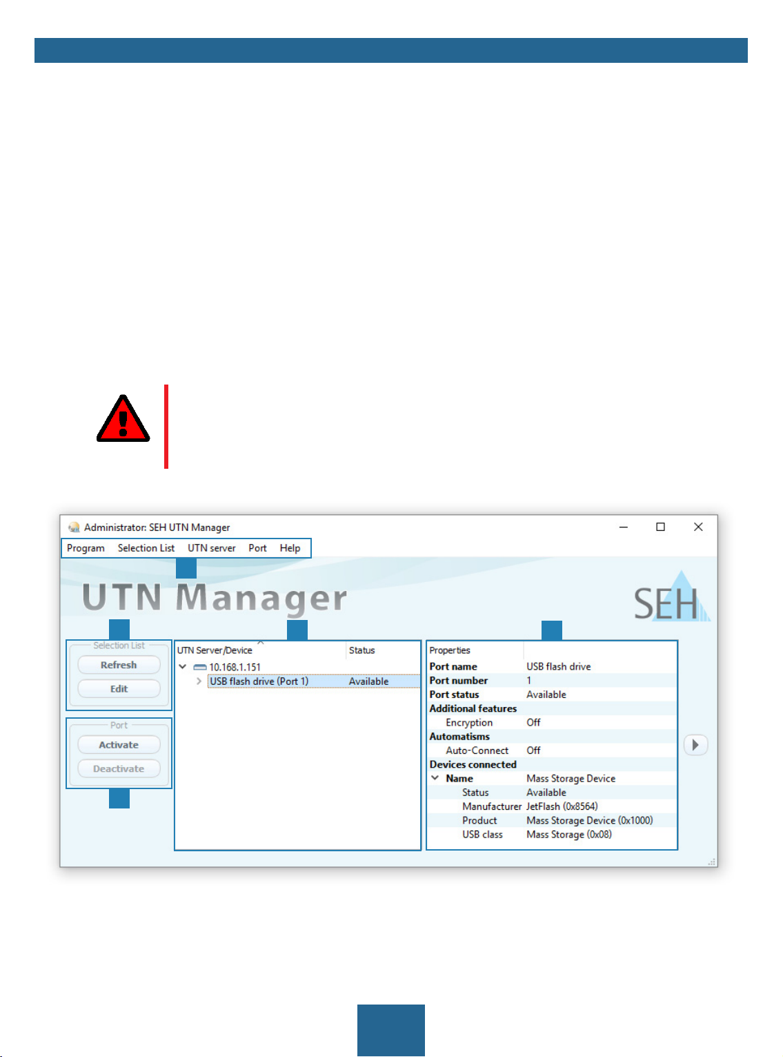
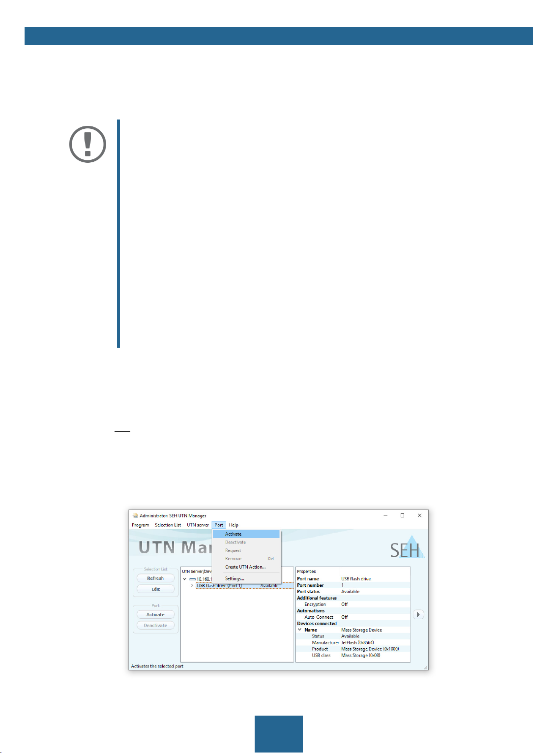
Figure 2: SEH UTN Manager
2
5
8
myUTN User Manual Windows Administration Methods
1 Menu bar Available menu items
2 Selection List Shows the selected UTN servers and the connected USB devices.
3 Buttons for editing the selec-
tion list
4 Buttons for managing the
port connection
5 Display area for the proper-
ties
Opens the dialog for searching UTN servers in the network and for select-
ing the desired devices 35.
Establishes a connection to the USB device connected to the USB port (
37) or interrupts the connection ( 38).
Shows information on the selected UTN server or USB device 42.
Detailed information on how to use the SEH UTN Manager can be found in the
Help'. To start the online help, go to the SEH UTN Manager menu bar and select Help – Online Help.
Important:
Some SEH UTN Manager features might not be displayed or are displayed as inactive. This depends on
• the type and location of the selection list
• the user's rights and the group memberships on the client
• the client operating system
• the settings of the product-specific security mechanisms
• the status of the UTN server and respective USB port
More details can be found in chapter ’SEH UTN Manager – Feature Overview’
97.
Versions
The SEH UTN Manager is available in two versions:
• Complete Version:
SEH UTN Manager with graphical user interface (Figure 2 8) and additional features.
• Minimal version (without graphical user interface):
Usage only via command line ('utnm' 45) and automated programs ('UTN Actions' 39).
'SEH UTN Manager Online
Important:
The complete version is recommended for general use.
The minimal version is to be used by experts only!
In both versions the 'SEH UTN Service' works in the background and is automatically active after the system start.
The service can be controlled by means of the usual administration methods.
Additionally, the following user groups are distinguished:
• users with administrative rights (administrator)
• users without administrative rights (standard user)
Important:
Some features can only be configured by administrators. More details can be
found in chapter ’SEH UTN Manager – Feature Overview’ 97.
9
myUTN User Manual Windows Administration Methods
Installation
In order to use the SEH UTN Manager, the program must be installed on a computer with a Windows operating
system. The SEH UTN Manager installation file can be found on the SEH Computertechnik GmbH website:
http://www.seh-technology.com/services/downloads.html
The installation file is available as '*.exe' for Windows systems. The file contains both versions of the SEH UTN Manager. Instead of the standard installation, an unattended installation may be carried out.
• ’Standard Installation’ 10
• ’Unattended Installation’ 10
Standard Installation
The SEH UTN Managers installation is suited for Windows XP or later except for Windows Vista and Windows
Server 2008.
(For Windows 7 and Windows Server 2008 R2 KB3033929 must be installed http://technet.microsoft.com/en-us/library/security/
3033929.)
The installation can only be carried out by users with administrative rights.
1. Start the SEH UTN Manager installation file.
2. Follow the installation routine.
The SEH UTN Manager is installed on your client.
If used in server-based environments (Citrix XenApp, Microsoft Remote Desktop Services/Terminal Services) and
virtualized environments (VMware, Citrix XenDesktop, Microsoft HyperV, etc.) the Windows system may lack required drivers. The installation routine checks the available drivers during the installation process. If drivers are
missing, another installer ('USB driver for SEH UTN Manager'). This installer will prepare the installation of the required drivers.
Unattended Installation
An unattended installation takes place without any time-consuming user input. In addition, the SEH UTN Manager UTN Manager can be automatically installed on a large number of clients via login scripts. For more information,
refer to the documentation of your operating system.
Default settings used:
• Complete version
• Installation for all users of the client
• Target directory:
%PROGRAMFILES%\SEH Computertechnik GmbH\SEH UTN Manager
(Where %PROGRAMFILES% is a Windows environment variable for the 'Programs' folder. By means of the command line, the path can be determined as follows:
• Start menu folder:
SEH Computertechnik GmbH\SEH UTN Manager
echo %PROGRAMFILES%)
• A desktop shortcut will be created.
• SEH UTN Manager will start automatically after the installation.
10
myUTN User Manual Windows Administration Methods
The SEH UTN Managers installation is suited for Windows XP or later except for Windows Vista and Windows
Server 2008.
(For Windows 7 and Windows Server 2008 R2 the following must be installed: KB3033929 http://technet.microsoft.com/en-us/library/
security/3033929 and hotfix 2921916 http://support.microsoft.com/en-us/help/2921916/the-untrusted-publisher-dialog-box-appears-when-you-install-a-driver-i.)
The installation can only be carried out by users with administrative rights.
Important:
By installing the SEH UTN Manager, you automatically accept the SEH Computertechnik GmbH agreement concerning the license and the use of the software. The
agreement can be found on the website of SEH Computertechnik GmbH:
http://www.seh-technology.com/services/licenses.html
1. Open the command-line interface.
2. Change to the directory containing the SEH UTN Manager installation file.
3. Enter the command sequence:
"sehutnmanager-win-X.X.X.exe" /S [<command>]
Commands: Table 1 11.
4. Confirm your entry.
The sequence of commands will be run.
Table 1: Installation commands
Command Description
/A
/C
/F=<folder name>
Installs SEH UTN Manager for all users.
Installs SEH UTN Manager for the current user only.
Overrides the default folder name of the Start menu folder. Subfolders can be
specified with '/'.
/G
Installs the complete version ( 10) of SEH UTN Manager.
Recommended for general use.
/I=<path>
Overrides the default installation directory. An absolute path must be specified.
It has to be the last parameter used in the command line and must not contain
any quotes, even if the path contains spaces.
/K
/M
Does not create a desktop shortcut.
Installs the minimal version ( 10) of SEH UTN Manager.
Expert use only!
/R
/S
Runs SEH UTN Manager after the installation is complete.
Instructs the installation to be silent. There is no user interaction and the user
cannot cancel the installation.
/U
Updates an existing SEH UTN Manager.
(If no SEH UTN Manager is installed, it will be installed using the default installa-
tion settings.)
/V1
/V2
Enables command line logging to troubleshoot installation problems.
Creates a log file in the installation folder. The file contains information to trou-
bleshoot installation problems.
/V3
Enables command line logging and creates a log file in the installation directory. Both provide information to help troubleshoot installation issues.
/?
Shows the help page.
11
myUTN User Manual Windows Administration Methods
Program Start
You recognize the SEH UTN Manager by its icon: . The program is started with the usual methods of your operating system.
Update
You can check for program updated manually and automatically. More information can be found in the 'SEH
UTN Manager Online Help'.
12
myUTN User Manual Windows Administration Methods
2.3 Administration via InterCon-NetTool
The InterCon-NetTool is a software tool developed by SEH Computertechnik GmbH for the administration of SEH
network devices (print servers, TPG, UTN servers and so on). Depending on the network device you can perform
different actions with the InterCon-NetTool.
• Function 13
• Installation 14
• Program Start 14
Function
After the InterCon-NetToolhas been started, the network will be scanned for connected network devices. The network range to be scanned is freely definable. All network devices found will be displayed in the 'device list'. You
can select and configure the devices in the device list.
WARNING
The InterCon-NetTool only works in IPv4 networks.
In IPv6-only networks only the myUTN Control Center ( 6) can be accessed to
administrate the UTN server.
If you can perform a task with the InterCon-NetTool it is described in the corresponding chapter.
1
2
1
4
5
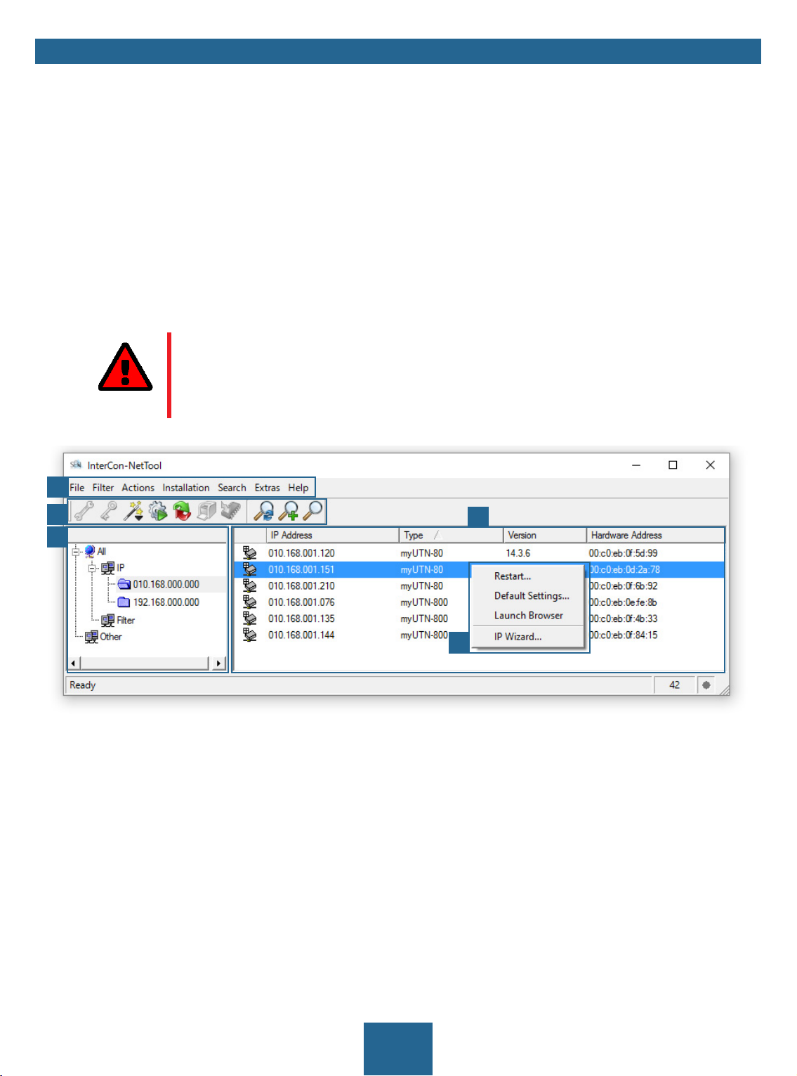
Figure 3: InterCon-NetTool
1 Menu bar Available menu items
2 Toolbar Available actions
3 Device list Shows devices available in the network and device information.
4 Filters for the device list Filters determine which devices are shown in the device list.
5 Shortcut menu Available device actions
Detailed information on how to use the InterCon-NetTool can be found in the 'InterCon-NetTool Online
Help'. To start the online help, go to the menu bar and select Help – Online Help.
13
myUTN User Manual Windows Administration Methods
Installation
In order to use the InterCon-NetTool, the program must be installed on a computer with Windows operating system. The installation file of the InterCon-NetTool can be found on the SEH Computertechnik GmbH homepage:
http://www.seh-technology.com/services/downloads.html
The installation file is available as '*.exe' for Windows systems.
1. Start the InterCon-NetTool installation file.
2. Select the desired language.
3. Follow the installation routine.
The InterCon-NetTool will be installed on your client.
Program Start
You can identify the InterCon-NetTool by its icon: . Start it with the usual methods of your operating system.
14

myUTN User Manual Windows Administration Methods
2.4 Administration via Email
You can administrate the UTN server via email and thus from any computer Internet access (remote access):
• Get UTN server status
• Set UTN server parameters
• UTN server update
To do so, you write commands into the email message header Table 2 15.
Table 2: Commands and comment:
Commands Option Description
<Command>
[<Comment>] Freely definable text for descriptions.
get status
get parameters
set parameters
update utn
help
You get the UTN server status page.
You get the UTN server parameter list.
Sends one or more parameters to the UTN server which will then
be adopted by the UTN server.
Write the parameters and their values into the email message
body:
<parameter> = <value>
The syntax and values can be found in the parameter lists 73.
Carries out an automatic update using the software that is
attached to the mail.
You get a page with information on remote maintenance.
The following applies to the instructions:
• not case-sensitive
• one or more space characters are allowed
• max. length is 128 byte
• only the ASCII format can be read.
In addition, a TAN is needed to execute updates or parameter changes. To begin with, you have to get a status
page via email (Table 2 15) because it contains the TAN. You enter the received TAN into the email message
body. A space character must follow.
A DNS server is configured on the UTN server 23.
In order to receive emails, the UTN server must be set up as user with its own email address on a POP3 server.
POP3 and SMTP parameters have been configured on the UTN server 25.
1. Open an email program.
2. Write a new email:
- As recipient enter the UTN server address.
- Into the subject line enter an instruction.
cmd: <command> [<comment>]
Commands and comment: Table 2 15.
- Into the email message body enter a TAN, if applicable.
3. Send the email.
The UTN server receives the email and carries out the instruction.
15

myUTN User Manual Windows Administration Methods
Examples
You want to get the UTN server parameter list:
To:
UTNserver@company.com
Subject: cmd: get parameters
You want to set the 'configuration' parameter:
To:
UTNserver@company.com
Subject: cmd: set parameters
Email message body: TAN = nUn47ir79Ajs7QKE
sys_descr = <Your description>
16

myUTN User Manual Windows Network Settings
3 Network Settings
To optimally embed your UTN server into your network, you can configure the following settings:
• How to Configure IPv4 Parameters 18
• How to Configure IPv6 Parameters 20
• How to Configure WLAN 21
• How to Configure the DNS 23
• How to Configure SNMP 23
• How to Configure Bonjour 24
• How to Configure Email (POP3 and SMTP) 25
• How to Use the UTN Server in VLAN Environments (only myUTN-80 and later) 27
17
myUTN User Manual Windows Network Settings
3.1 How to Configure IPv4 Parameters
In the hardware installation ( ‘Hardware Installation Guide‘) the UTN server is connected to the network. The
UTN server then checks if it gets IP address dynamically via the boot protocols BOOTP (Bootstrap Protocol) or
DHCP (Dynamic Host Configuration Protocol). If this is not the case, the INU server assigns itself an IP address via
Zeroconf from the address range which is reserved for Zeroconf (169.254.0.0/16).
Important:
If the UTN server is connected to an IPv6 network, it will automatically receive an
additional IPv6 address 20.
The IPv4 address assigned to the UTN server can be found via the software tools 'SEH UTN Manager' and 'InterCon-NetTool'. This step usually is carried out during the initial set up (
To optimally embed the UTN server into a TCP/IP network, you can configure different IPv4 parameters and/or
manually assign a static IP address to the UTN server.
• Configuring IPv4 Parameters via the myUTN Control Center 18
• Configuring IPv4 Parameters via SEH UTN Manager 19
• Determining the IPv4 Address via SEH UTN Manager and Configuring IPv4 Parameters 19
• Determining the IPv4 Address via InterCon-NetTooland/or Configuring IPv4 Parameters 19
‘Quick Installation Guide‘).
Configuring IPv4 Parameters via the myUTN Control Center
1. Start the myUTN Control Center.
2. Select NETWORK – IPv4.
3. Configure the IPv4 parameters; Table 3 18.
4. Click Save & Restart to confirm.
The settings will be saved.
Table 3: IPv4 parameters
Parameters Description
DHCP
BOOTP
ARP/PING
IP address IP address of the UTN server.
Subnet mask Subnet mask of the UTN server.
Gateway IP address of the network's standard gateway which the UTN server uses.
Enables or disables the protocols DHCP, BOOTP, and ARP/PING.
The IP address assignment via DHCP and BOOTP is automatic if one of these
protocols is implemented in your network.
You can use the commands ARP and PING to change an IP address which was
assigned via Zeroconf. The implementation depends on your system; read the
documentation of your operating system.
We recommend disabling these options once an IP
address has been assigned to the UTN server.
Subnet masks are used to logically partition big networks into subnetworks. If
you are using the UTN server in a subnetwork, it requires the subnet mask of
the subnetwork.
With a gateway, you can address IP addresses from other networks.
18
myUTN User Manual Windows Network Settings
Configuring IPv4 Parameters via SEH UTN Manager
The SEH UTN Manager (complete version) is installed on the client 8.
The UTN server is shown in the selection list 35.
1. Start the SEH UTN Manager.
2. In the selection list, select the UTN server.
3. In the menu bar, select UTN Server–Set IP Address.
The Set IP Address dialog appears.
4. Enter the relevant TCP/IP parameters.
5. Click OK.
The settings will be saved.
Determining the IPv4 Address via SEH UTN Manager and Configuring IPv4 Parameters
The SEH UTN Manager searches the network for connected INU servers.
The SEH UTN Manager (complete version) is installed on the client 8.
1. Start the SEH UTN Manager.
2. Confirm the note dialog Your Selection List seems to be empty with Yes.
If no note dialog is available and the main dialog appears, select Selection List–Edit in the menu bar.
The Edit Selection List dialog appears.
3. In the network list, select the INU server.
If you are using several UTN servers of the same model, you can identify a specific device by its default name ( 69) or the connected USB devices.
4. In the shortcut menu, select Set IP Address.
The Set IP Address dialog appears.
5. Enter the relevant TCP/IP parameters.
6. Click OK.
The settings will be saved.
Determining the IPv4 Address via InterCon-NetTooland/or Configuring IPv4 Parameters
The InterCon-NetTool is installed on the client 13.
The network scan via multicast is enabled in the InterCon-NetTool.
1. Start the InterCon-NetTool.
2. In the device list, select the UTN server.
If you do not know the IP address, you can identify the UTN server in several ways:
- by its type
- if your are using several UTN servers of the same model, by its hardware address
(which can be found in the type plate at the device bottom)
- if the UTN server received its address via Zeroconf, it will appear under the filter 'Zeroconf'
3. In the menu, select Installation–IP Wizard.
Der IP Wizard is started.
4. Follow the instructions of the wizard.
The settings will be saved.
19
myUTN User Manual Windows Network Settings
3.2 How to Configure IPv6 Parameters
IPv6 (Internet Protocol Version 6) is the successor of the still predominantly used IPv4 (Internet Protocol Version
128
4). IPv6 offers the same basic functions but has many advantages such as the increased address space of 2
32
(IPv6) instead of 2
(IPv4) IP addresses and auto configuration.
Important:
IPv6 address notation differs from IPv4: An IPv6 address consists of 128 bits. The
normal format of an IPv6 address is eight fields. Each field contains four hexadecimal digits representing 16 bits.
Example:
2001:db8:4:0:2c0:ebff:fe0f:3b6b
As a URL in a Web browser, an IPv6 address must be enclosed in square brackets.
This prevents port numbers from being mistakenly regarded as part of an IPv6
address.
Example:
http://[2001:db8:4:0:2c0:ebff:fe0f:3b6b]:443
The URL will only be accepted by browsers that support IPv6.
You can embed the UTN server into an IPv6 network.
WARNING
UTN ( 1) and the corresponding SEH UTN Manager only work in IPv4 networks.
The InterCon-NetTool also only works in IPv4 networks.
In IPv6-only networks only the myUTN Control Center ( 6) can be accessed to
administrate the UTN server.
The UTN server will automatically receive one or more IPv6 addresses in addition to its IPv4 address. To optimally
embed the UTN into your network, you can configure IPv6 parameters.
1. Start the myUTN Control Center.
2. Select NETWORK – IPv6.
3. Configure the IPv6 parameters; Table 4 20.
4. Click Save & Restart to confirm.
The settings will be saved.
Table 4: IPv6 parameters
Parameters Description
IPv6 Enables/disables the IPv6 functionality of the UTN server.
Automatic configuration Enables/disables the automatic assignment of the IPv6 address to the UTN
server.
IPv6 address Defines an IPv6 unicast address in the format n:n:n:n:n:n:n:n which is manually
assigned to the UTN server.
• Every 'n' represents the hexadecimal value of one of the eight 16 bit elements of the address.
• Leading zeros can be omitted.
• An IPv6 address may be entered or displayed using a shortened version when
successive fields contain all zeros (0). In this case, two colons (::) are used.
Router Manually defines a static router to which the UTN server sends its requests.
20
myUTN User Manual Windows Network Settings
Parameters Description
Prefix length Defines the length of the subnet prefix for the IPv6 address. The value 64 is pre-
set.
Address ranges (e.g. your network) are specified with prefixes. To do this, the
prefix length (number of bits used) is added to the IPv6 address as a decimal
number and the decimal number is preceded by '/'.
3.3 How to Configure WLAN
The 'myUTN-55' is a WLAN device (Wireless Local Area Network) and supports the following standards:
• IEEE 802.11b
• IEEE 802.11g
• IEEE 802.11n
You can view the current WLAN settings in the myUTN Control Center under NETWORK – WLAN.
To optimally integrate the UTN server into your network, configure the WLAN parameters to match your WLAN
settings (network name, encryption, etc.). For this purpose, the UTN server must already be embedded into your
WLAN and be addressable. The initial setup is described in your product's
You know the settings of the WLAN.
The UTN server is within the WLAN range.
'Quick Installation Guide'.
Important:
If the UTN server changes the network, it may receive a new IP configuration. If this
is the case, the connection to the myUTN Control Center is interrupted.
1. Start the myUTN Control Center.
2. Select NETWORK – WLAN.
3. Configure the WLAN parameters; Table 5 21.
4. Click Save & Restart to confirm.
The settings will be saved.
Table 5: WLAN parameters
Parameters Description
Mode Defines the communication mode (network infrastructure):
• Ad hoc: Your WLAN is a decentralized ad-hoc-network in which devices
communicate directly with each other (peer-to-peer).
• Infrastructure: Your WLAN is an infrastructure network with an access point/
router as centrals communication hub. The access point is connected to the
fixed network with a cable.
Network name (SSID) Enter your WLAN’s network name, also known as SSID (Service Set Identifier).
21
myUTN User Manual Windows Network Settings
Parameters Description
Roaming Enables/disables roaming (switching from one access point/router to another):
If your WLAN covers a widespread area with several access points/routers (with
identical settings) and the UTN server changes position, the UTN server will
automatically switch to the better signal without loss of connection if roaming
is activated.
(Infrastructure mode only)
Channel Enter your WLAN's channel (frequency range).
(Ad hoc mode only)
WARNING
Only use WLAN channels authorized for your country!
The UTN is an international product which supports a number of
channels. Channels are statutorily regulated by national authorities. So the UTN server might support channels which are forbidden to use in your country.
Inform yourself about national regulations.
Encryption method Select the encryption method that protects your WLAN.
Important:
We recommend to use hexadecimal keys for WEP.
Some access points/routers convert WEP keys in ASCII format to
hexadecimal format. In this case, the ASCII key on the UTN server
and the hexadecimal key on the access point/router do not match.
Use WEP key Defines the WEP key to be used.
Key 1–4 Defines the WEP keys. Four WEP keys are available. The key type defines the
max. number of characters as well as the permitted character set for the WEP
keys.
Important:
If your access point supports multiple WEP keys, make sure that
the key numbers on access point and UTN server are identical.
Example: The ABCDE must have the number 2 on both devices
(and not 1 on the access point and 2 on the UTN server).
PSK Defines the Pre Shared Key (PSK) for Wi-Fi Protected Access (WPA).
Authentication method Choose the authentication mechanism which is used in your WLAN.
For further information see ’How to Configure Network Authentication (IEEE
802.1X)’ 60.
22
myUTN User Manual Windows Network Settings
3.4 How to Configure the DNS
DNS is a service to translate domain names into IP addresses and vice versa. Enable DNS so that you can enter host
names instead of IP addresses when you define servers.
Example: Time server configuration ( 29) with
Important:
If your network in configured accordingly, the UTN server receives the DNS settings
automatically via DHCP. A DNS server assigned in such a manner always takes precedence over manual settings.
Your network has a DNS server.
1. Start the myUTN Control Center.
2. Select NETWORK – DNS.
3. Configure the DNS parameters; Table 6 23.
4. To confirm, click
The settings will be saved.
Table 6: DNS parameters
Parameters Description
Save.
ntp.server.de instead of 10.168.0.140.
DNS Enables/disables the name resolution via a DNS server.
Primary DNS server Defines the IP address of the primary DNS server.
Secondary DNS server Defines the IP address of the secondary DNS server.
The secondary DNS server is used if the first one is not available.
Domain name (suffix) Defines the domain name of an existing DNS server.
3.5 How to Configure SNMP
SNMP (Simple Network Management Protocol) is protocol for configuring and monitoring network elements. The
protocol controls communication between the monitored devices and the monitoring station (SNMP management tool). Information can be read and changed.
SNMP exists in 3 versions, the UTN supports version 1 and 2.
SNMPv1
SNMPv1 is the first and most simple SNMP version. A disadvantage is the insecure access control which is the community: a community groups monitoring station and monitored devices. This makes their administration easier.
There are two types of communities, read-only and read/write. For both the community name is also the password used between the monitoring station and the monitored devices. As it is transmitted as clear text, it does
not offer sufficient protection.
SNMPv3
SNMPv3 is the newest SNMP version. It contains enhancements and a new security concept which includes,
amongst other thins, encryption and authentication. Therefore, a SNMP user with name and password must be
created in the monitoring station. This user must then be specified in the UTN server.
Important:
The user accounts are also used to access the myUTN Control Center and thus are
to be defined under SECURITY - Device access ’How to Protect Access to the
myUTN Control Center (User Accounts)’ 53.
23
myUTN User Manual Windows Network Settings
SNMPv3 users are created in the monitoring station. (Only for SNMPv3.)
The SNMPv3 users from the monitoring station are specified on the UTN server 53. (Only for SNMPv3.)
1. Start the myUTN Control Center.
2. Select NETWORK – SNMP.
3. Configure the SNMP parameters; Table 7 24.
4. To confirm, click Save.
The settings will be saved.
Table 7: SNMP Parameters
Parameters Description
SNMPv1 Enables/disables SNMPv1.
Read-only Enables/disables the write protection for the community.
Community SNMP community name Enter the name as it is defined in the monitoring sta-
tion.
Important:
The default name is 'public'. This name is commonly used for read/
write communities. We recommend to change it as soon as possible to increase security.
SNMPv3 Enables/disables SNMPv3.
Hash Defines the hash algorithm.
Access rights Defines the access rights of the SNMP user.
Encryption Defines the encryption method.
3.6 How to Configure Bonjour
Bonjour is a technology which automatically detects devices and services in TCP/IP networks.
The UTN server uses Bonjour to
• verify IP addresses
• announce and find network services
• match host names and IP addresses
1. Start the myUTN Control Center.
2. Select NETWORK – Bonjour.
3. Configure the Bonjour parameters; Table 8 24.
4. To confirm, click Save.
The settings will be saved.
Table 8: Bonjour parameters
Parameters Description
Bonjour Enables/disables Bonjour.
Bonjour name Defines the Bonjour name of the UTN server.
The UTN server uses this name to announce its Bonjour services. If no Bonjour
name is entered, a default name will be used (device name@ICxxxxxx).
24
myUTN User Manual Windows Network Settings
3.7 How to Configure Email (POP3 and SMTP)
The UTN server can be administered via email ( 15) and offers a notification service ( 31) which sends you
status and error messages via email. To use these features, the email protocols 'POP3' and 'SMTP' must be set up
on the UTN server.
A client, e.g. the UTN server, uses POP3 (Post Office Protocol Version 3) to fetch emails from a mail server. POP3
must be set up on the UTN server so that it can be administered via email.
SMTP (Simple Mail Transfer Protocol) is used to send and forward emails. The UTN server needs SMTP for the administration via email and the notification service.
• Configuring POP3 25
• Configuring SMTP 25
Configuring POP3
An email user account for the UTN server is set up on the POP3 server.
1. Start the myUTN Control Center.
2. Select NETWORK – Email.
3. Configure the POP3 parameters; Table 9 25.
4. To confirm, click Save.
The settings will be saved.
Table 9: POP3 parameters
Parameters Description
POP3 Enables/disables the POP3 functionality.
POP3 – Server name Defines the POP3 server via its IP address or host name.
A host name can only be used if a DNS server was configured beforehand.
POP3 – Server port Defines the port which the UTN server uses to receive emails.
The default port number for POP3 is 110. The default port number for SSL/TLS
(parameter ’POP3 – Security’ 25) is 995. If required, read the documentation
of your POP3 server.
POP3 – Security Defines the authentication method to be used:
• APOP: encrypts the password when logging on to the POP3 server.
• SSL/TLS: encrypts the entire communication with the POP3 server. The en-
cryption strength is defined via the encryption protocol and level 51.
POP3 – Check mail every Defines the time interval (in minutes) which with the POP3 server is checked for
emails.
POP3 – Ignore mail exceeding
POP3 – User name Defines the user name used by the UTN server to log on to the POP3 server.
POP3 – Password Defines the user password used by the UTN server to log on to the POP3 server.
Defines the maximum email size (in Kbyte) to be accepted by the UTN server.
(0 = unlimited)
Configuring SMTP
An email user account for the UTN server is set up on the SMTP server.
1. Start the myUTN Control Center.
2. Select NETWORK – Email.
3. Configure the SMTP parameters; Table 10 26.
25
myUTN User Manual Windows Network Settings
4. To confirm, click Save.
The settings will be saved.
Table 10: SMTP Parameters
Parameters Description
SMTP - Server name Defines the SMTP server via the IP address or the host name.
A host name can only be used if a DNS server was configured beforehand.
SMTP – Server port Defines the port which the UTN server and SMTP server use to communicate.
The default port number for SMTP is 25. For SSL/TLS (parameter ’SMTP – SSL/
TLS’ 26), SMTP servers use by default port 587 (STARTSSL/STARTTLS) or the
old port 465 (SMTPS). If required, read the documentation of your SMTP server.
SMTP – SSL/TLS Enables/disables SSL/TLS.
SSL/TLS encrypts the communication from the UTN to the SMTP server. The
encryption strength is defined via the encryption protocol and level 51.
SMTP – Sender name Defines the email address used by the UTN server to send emails.
Very often the name of the sender and the email account user name are identical.
SMTP – Login Enables/disables SNMP authentication. To send emails, the UTN sends its user
name and password to the SMTP server to authenticate itself. Enter user name
(parameter ’SMTP – User name’ 26) and password (parameter ’SMTP – Pass-
word’ 26).
Some SMTP servers require SMTP authentication to prevent fraudulent use
(spam).
SMTP – User name Defines the user name used by the UTN server to log on to the SMTP server.
SMTP – Password Defines the password used by the UTN server to log on to the SMTP server.
SMTP – Security (S/MIME) Enables/disables the email security standard S/MIME (Secure/Multipurpose
Internet Mail Extensions). S/MIME is used to sign (’SMTP – Signing emails’
26) or encrypt (’SMTP – Full encryption’ 26) emails.Enable the desired fea-
tures (if desired with ’SMTP – Attach public key’ 26).
SMTP – Signing emails Enables the signing of emails. The recipient can use the signature to check the
sender's identity. This proves, that the email has not been altered.
An S/MIME certificate is required for the signing of emails 56.
SMTP – Full encryption Enables the encryption of emails. Only the intended recipient can open and
read the encrypted email.
An S/MIME certificate is required for the encryption 56.
SMTP – Attach public key Sends the public key together with the email.
Many email clients require the key to display the email.
26

myUTN User Manual Windows Network Settings
3.8 How to Use the UTN Server in VLAN Environments (only myUTN-80 and later)
The UTN server supports VLAN (Virtual Local Area Network) according to 802.1Q.
A VLAN divides a physical network into logical subnetworks. Each subnetwork is its own broadcast domain, so
data packets cannot be exchanged between subnetworks. VLANs are used to structure networks and, above all,
to secure them.
Each USB device can be assigned to a VLAN. To transfer VLAN data via the USB ports, you must first enter the
VLANs on the UTN server. After this, the USB ports used for forwarding data must be linked to the specified VLANs.
The access to USB devices can be regulated particularly well with VLAN: a defined
group of network users may use certain USB devices.
Inform yourself on how to implement VLAN in your environment and then set up the
UTN server for it.
• Define a IPv4 Management VLAN 27
• Define a IPv4 Client VLAN 27
• Allocating a IPv4 Client VLAN to a USB Port 28
Define a IPv4 Management VLAN
1. Start the myUTN Control Center.
2. Select NETWORK – IPv4 VLAN.
3. Configure the IPv4 VLAN parameters; Table 11 27.
4. To confirm, click Save.
5. The settings will be saved.
Table 11: IPv4 management VLAN parameters
Parameters Description
IPv4 management VLAN Enables/disables the forwarding of IPv4 management VLAN data.
If this option is enabled, SNMP is only available in the IPv4 management VLAN.
VLAN ID ID for the identification of the IPv4 management VLAN (0–4096).
IP address IP address of the UTN server 18.
Subnet mask Subnet mask of the UTN server 18.
Gateway IP address of the network's standard gateway which the UTN server uses
18.
With a gateway, you can address IP addresses from other networks.
Access from any VLAN Enables/disables the administrative access (web) to the UTN server via IPv4 cli-
ent VLANs.
If this option is enabled, the UTN server can be administrated via all VLANs.
Access via LAN (untagged) Enables/disables the administrative access to the UTN server via IPv4 packets
without tag.
If this option is disabled, the UTN server can only be administrated via VLANs.
Define a IPv4 Client VLAN
1. Start the myUTN Control Center.
2. Select NETWORK – IPv4 VLAN.
27

myUTN User Manual Windows Network Settings
3. Configure the IPv4 VLAN parameters; Table 12 28.
4. To confirm, click Save.
The settings will be saved.
Table 12: IPv4 client VLAN parameters
Parameters Description
VLAN Enables/disables the forwarding of IPv4 client VLAN data.
IP address IP address of the UTN server within the IPv4 client VLAN.
Subnet mask Subnet mask of the UTN server within the IPv4 client VLAN.
Gateway Gateway address of the IPv4 client VLAN.
VLAN ID ID for the identification of the IPv4 client VLAN (0–4096).
Use Auto-fill to automatically fill VLAN, IP address and Subnetmask with the values from line 1. VLAN ID will automatically be counted up by '1'.
Allocating a IPv4 Client VLAN to a USB Port
1. Start the myUTN Control Center.
2. Select SECURITY – USB port access.
3. Allocate a VLAN to the USB port via the Allocate VLAN list.
4. To confirm, click Save.
The settings will be saved.
28

myUTN User Manual Windows Device Settings
4 Device Settings
• How to Configure the Device Time 29
• How to Assign a Description 29
• How to Assign a Name to a USB Port 30
• How to Disable a USB Port (only myUTN-80 and later) 30
• How to Configure the UTN (SSL) Port 31
• How to Get Messages (only myUTN-80 and later) 31
• How to Configure Acoustic Signals (myUTN-800 only) 32
• How Do I Determine What is Shown in the Display? (myUTN-800 only) 33
4.1 How to Configure the Device Time
The device time of the UTN server can be set via an SNTP time server (Simple Network Time Protocol) in the network. A time server synchronizes the time of devices within a network.
Today's primary time standard 'UTC' (Universal Time Coordinated) is used. The time zone compensates for location.
Important:
If your network in configured accordingly, the UTN server receives the time server
settings automatically via DHCP. A time server assigned in such a manner always
takes precedence over a manually set time server.
The network has a time server.
1. Start the myUTN Control Center.
2. Select DEVICE – Date/Time.
3. Tick Date/Time.
4. Into the Time server box, enter the IP address or the host name of the time server.
(The host name can only be used if a DNS server was configured beforehand 23.)
5. From the Time zone list, select the code for your local time zone.
6. To confirm, click Save.
The settings will be saved.
4.2 How to Assign a Description
You can assign freely definable descriptions to the UTN server. This gives you a better overview of the devices in
the network.
You can also assign names to USB ports to distinguish them 30.
1. Start the myUTN Control Center.
2. Select DEVICE – Description.
3. Enter freely definable names for Host name, Description, and Contact person.
4. To confirm, click Save.
The settings will be saved.
29

myUTN User Manual Windows Device Settings
Table 13: Description
Parameters Description
Host name Device name as alternative to IP address. With a name you can identify the UTN
server more easily in the network, e.g. if you are using several UTN servers.
Is displayed in the myUTN Control Center, SEH UTN Manager and InterCon-Net-
Tool.
Description Device description, e.g. location or department.
Is displayed in the myUTN Control Center, SEH UTN Manager and InterCon-NetTool.
Contact person Contact person, e.g. device administrator.
Is displayed in the myUTN Control Center.
4.3 How to Assign a Name to a USB Port
By default, the names of the connected USB devices are displayed on the USB ports in the myUTN Control Center
and SEH UTN Manager. These names are specified by the device manufacturers and might be ambiguous or inaccurate.
That is why you can assign freely definable names to the USB ports, e.g. the name of a corresponding software.
This gives you a better overview of the USB devices available in the network.
1. Start the myUTN Control Center.
2. Select Device – USB port.
3. Enter the preferred name into the Port name field.
4. To confirm, click Save.
The settings will be saved.
4.4 How to Disable a USB Port (only myUTN-80 and later)
By default all USB ports are active. You can deactivate (and re-activate ) the USB port by interrupting respectively
re-establishing the power supply.
Deactivate
• unused USB ports to ensure that unwanted USB devices cannot be connected to the network. (Deactivated
USB ports cannot be seen in the SEH UTN Manager.)
• a USB port and re-activate it to restart the connected USB device if it is in an undefinable condition. (The USB
device does not need to be removed and reconnected manually.)
1. Start the myUTN Control Center.
2. Select Device – USB port.
3. Tick/clear the option in front of the USB port.
4. To confirm, click Save.
The USB port is disabled/enabled.
30

myUTN User Manual Windows Device Settings
4.5 How to Configure the UTN (SSL) Port
A shared port is used for the data transfer between the UTN server (including connected USB devices) and the client. It depends on the connection type:
•
unencrypted USB connection: UTN port (default = 9200)
encrypted USB connection ( 49): UTN SSL port (default = 9443)
•
WARNING
The UTN port respectively UTN SSL port must not be blocked by security measures
(firewall).
You can change the port number, e.g. if the port number is already used for another application in your network.
The change is made on the UTN server and is relayed to the SEH UTN Manager installed on the clients via SNMPv1.
SNMPv1 is enabled 23.
1. Start the myUTN Control Center.
2. Select Device – UTN port.
3. Enter the port number into the UTN port or UTN SSL port box.
4. To confirm, click Save.
The settings will be saved.
4.6 How to Get Messages (only myUTN-80 and later)
The UTN server can send you different messages:
• Status email: Periodically sent email containing the status of the UTN server and of the connected USB devices.
• Event notification via email or SNMP trap:
- USB device is connected to the UTNserver / disconnected from the UTN server
- USB port (i.e. connection to the connected USB device) is activated/deactivated
- UTN server restart
- power supply is interrupted/established (myUTN-800 only)
- network connection is interrupted/established (myUTN-800 only)
- SD card is inserted into the UTNserver / removed from the UTN server (myUTN-800 only)
- SC card cannot be used (myUTN-800only)
• Configuring the sending of status emails 31
• Configuring event notifications via email 32
• Configuring event notifications via SNMP traps 32
Configuring the sending of status emails
The status email can be sent to up to two recipients.
SMTP is set up 25.
DNS is set up 23.
1. Start the myUTN Control Center.
2. Select DEVICE – Notification.
3. Enter the recipient into the Email address box.
4. Tick the desired recipient(s) in the Status email area.
5. Define the interval.
31

myUTN User Manual Windows Device Settings
6. To confirm, click Save.
The settings will be saved.
Configuring event notifications via email
The event emails can be sent to up to two recipients.
SMTP is set up 25.
DNS is set up 23.
1. Start the myUTN Control Center.
2. Select DEVICE – Notification.
3. Enter the recipient into the Email address box.
4. Tick the options with the desired message types.
5. To confirm, click Save.
The settings will be saved.
Configuring event notifications via SNMP traps
The event SNMP traps can be sent to up to two recipients.
SNMPv1 or/and SNMPv3 is set up 23.
1. Start the myUTN Control Center.
2. Select DEVICE – Notification.
3. In the SNMP traps area, define the recipients via the IP address and the community.
4. Tick the options with the desired message types.
5. To confirm, click Save.
The settings will be saved.
4.7 How to Configure Acoustic Signals (myUTN-800 only)
The myUTN-800 Dongleserver gives acoustic feedback if:
• a USB dongle is connected
• the Dongleserver restarts
• the parameters are reset
These acoustic signals cannot be turned off.
Optionally, you can configure additional acoustic feedback for the following events:
• only one power supply works
• SD card errors (read and write errors, no SD card)
• only one network connection is established
These optional acoustic signals ideally complement the error messages in the display
panel 33.
1. Start the myUTN Control Center.
2. Select DEVICE – Notification.
3. In the Acoustic signal area, tick the options with the desired message types.
4. To confirm, click Save.
The settings will be saved.
32

myUTN User Manual Windows Device Settings
4.8 How Do I Determine What is Shown in the Display? (myUTN-800 only)
The Dongleserver myUTN-800 has a display panel at its front side. The following information can be displayed:
• Identifier Freely definable name which will be displayed as default. (Default: DS)
• Error states: Optional notifications which can be displayed if these events occur:
- only one power supply works
- SD card errors (read and write errors, no SD card)
- only one network connection is established
The Errors are displayed in codes.
Table 14: Error codes
Te xt Description Troubleshooting
DS
(respective identifier)
RS The Dongleserver is restarting. –
DL Firmware/software is loaded onto the
E1 One of the two power supplies is not
E2 The SD card is formatted with an unsup-
E3 The SD card is read-only. Remove the write protection from the SD
E4 No SD card is available in the card reader. Insert an SD card into the SD card reader:
E5 One or both network connections have
The Dongleserver is operational. –
Dongleserver. Afterwards the Dongleserver is updated.
working.
Which connection is not working is indi-
cated by a glowing dot (left dot, left
power supply; right dot, right power supply).
ported file system respectively cannot be
read and be written to.
no link.
–
Check the cabling connections and voltage source.
• Format the SD card in the file format
FAT32, FAT16 or FAT12.
• Check if the SD card functions properly.
card.
• Type: SD or SDHC
• File system: FAT32, FAT16, or FAT12
Check the cable connections and your
network.
• Configuring the Identifier 33
• Enable Error Notifications 34
Configuring the Identifier
Use the identifier to identify devices if you have installed several myUTN-800 in a server rack or at the same location.
1. Start the myUTN Control Center.
2. Select DEVICE – Description.
3. Enter a freely definable description into the Identifier (display panel) box.
33

myUTN User Manual Windows Device Settings
(Max. 2 characters; A–Z, 0–9. E+digit is not permitted because this combination is used for errors.)
4. To confirm, click Save.
The settings will be saved.
Figure 4: Display panel myUTN-800
Enable Error Notifications
1. Start the myUTN Control Center.
2. Select DEVICE – Notification.
3. In the Display panel area, tick the options with the desired message types.
4. To confirm, click Save.
The settings will be saved.
The optional acoustic signals ideally complement the error messages in the display
panel 32.
34

myUTN User Manual Windows Working with the SEH UTN Manager
5 Working with the SEH UTN Manager
The 'SEH UTN Manager' is a software tool developed by SEH Computertechnik GmbH. The SEH UTN Manager is
used to establish and manage connections to the USB devices connected to the UTN servers.
• How to Find UTN Servers/USB Devices in the Network 35
• How to Establish a Connection to a USB Device 37
• How to Cut the Connection between the USB Device and the Client 38
• How to Request an Occupied USB Device 38
• How to Automate USB Device Connections and Program Starts 39
• How to Find Status Information on USB Ports and USB Devices 42
• How to Use the Selection List and Manage User Access Rights with It 42
• How to Use the SEH UTN Manager without Graphical User Interface (utnm) 45
5.1 How to Find UTN Servers/USB Devices in the Network
The software tool SEH UTN Manager is used to establish and manage connections to the USB devices connected
to the UTN servers.
After the SEH UTN Manager is started, the network has to be scanned for connected UTN servers. The network
range to be scanned is freely definable; the search can be effected via multicast and/or in definable IP ranges. The
default setting is multicast search in the local network segment.
All UTN servers found and their connected USB devices are displayed in the 'network list'. To use the USB devices
connected to the UTN server, you have to add the UTN server to the 'selection list'.
You can also directly add an UTN server to the selection list. To do this, you need to know its IP address.
• Defining Search Parameters 35
• Scanning the Network 35
• Adding the UTN Server to the Selection List 36
• Adding a UTN Server via IP Address 36
Defining Search Parameters
The SEH UTN Manager (complete version) is installed on the client 8.
1. Start the SEH UTN Manager.
2. In the menu bar, select Program–Options.
The Options dialog appears.
3. Select the Network Scan tab.
4. Tick IP Range Search and define one or more network ranges.
5. Click OK.
The settings will be saved.
Scanning the Network
The SEH UTN Manager (complete version) is installed on the client 8.
1. Start the SEH UTN Manager.
2. In the menu bar, select Selection List – Edit.
The Edit Selection List dialog appears.
3. Click Scan.
4. The network is scanned. The UTN servers and USB devices found are displayed in the network list.
35
myUTN User Manual Windows Working with the SEH UTN Manager
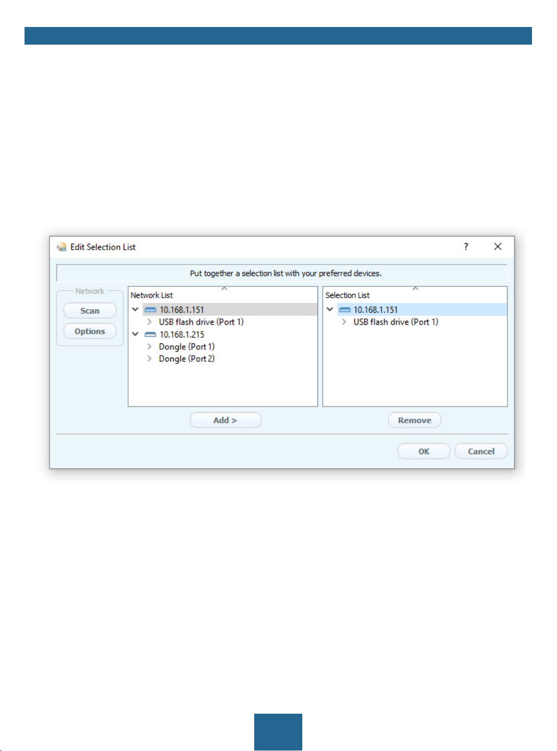
Adding the UTN Server to the Selection List
The SEH UTN Manager (complete version) is installed on the client 8.
The UTN server was found via the network scan and is displayed in the network list.
1. Start the SEH UTN Manager.
2. In the menu bar, select Selection List – Edit.
The Edit Selection List dialog appears.
3. In the network list, select the UTN server to be used.
4. Click Add.
(Repeat steps 2 and 3, if necessary.)
5. Click OK.
The UTN servers and the connected USB devices are shown in the selection list.
Figure 5: SEH UTN Manager – Edit Selection List
Adding a UTN Server via IP Address
The SEH UTN Manager (complete version) is installed on the client 8.
You know the IP address of the UTN server.
1. Start the SEH UTN Manager.
2. Select UTN server – Add.
The Add server dialog appears.
3. In the Host name or IP address box, enter the IP address of the UTN server.
4. If you changed the UTN port or UTN SSL port ( 31), define the respective port numbers in the UTN-Port
and UTN-SSL-Port box.
5. Click OK.
The UTN server and the connected USB devices is shown in the selection list.
36
myUTN User Manual Windows Working with the SEH UTN Manager
5.2 How to Establish a Connection to a USB Device
To connect a USB device to the client, a point-to-point-connection is established between the client and the USB
port of the UTN server to which the USB device is connected. The USB device can then be used as if it were directly
connected to the client.
Important:
Special case of compound USB devices
When connecting certain USB devices to a USB port of the UTN server, the selection
list displays several USB devices on this port. These are compound USB devices.
They consist of a hub and one or more USB devices that are all integrated into a single housing.
If the connection is established to a port with a connected compound USB device,
all USB devices shown will be connected to the user's client. In this case, each integrated USB device occupies a virtual USB port of the UTN server. The number of
these virtual USB ports is limited depending on the UTN server model. If the limit is
reached, no further USB devices can be used on this UTN server.
Number of virtual
UTN server
myUTN-50a 6 myUTN-800 40
myUTN-55 6 myUTN-2500 12
myUTN-80 16
USB ports UTN server
Number of virtual
USB ports
The SEH UTN Manager (complete version) is installed on the client 8.
The USB port is shown in the selection list 35.
All provisions (driver installation, etc.) necessary to operate the USB device locally (i.e. connected directly to
the client) have been met on the client. Ideally, the USB device has been connected and operated on the client
locally according to the instructions of the manufacturer.
The USB port is
1. Start the SEH UTN Manager.
2. In the selection list, select the port.
3. In the menu bar, select Port – Activate.
The connection between the USB device and client is established.
not connected to another client.
Figure 6: SEH UTN Manager – USB port activation
37
myUTN User Manual Windows Working with the SEH UTN Manager
5.3 How to Cut the Connection between the USB Device and the Client
If a USB device is connected to a client, the connection is of a point-to-point type. As long as the connection is
established, other users cannot connect the USB device to their client and thus cannot use it. For this reason, you
have to cut the connection once you do not use the USB device any longer.
To cut the connection between USB device and client, you deactivate the connection between the client and the
USB port of the UTN server to which the USB device is connected.
• Usually the connection is cut by the user via the SEH UTN Manager 38.
• In addition, the administrator can deactivate the connection via the myUTN Control Center 38.
• You can also set up an automatic deactivation (Auto Disconnect) 39.
Cutting the Device Connection via the SEH UTN Manager
The SEH UTN Manager (complete version) is installed on the client 8.
The USB port is shown in the selection list 35.
The USB port is connected to your client 37.
1. Start the SEH UTN Manager.
2. In the selection list, select the port.
3. Select Port – Deactivate from the menu bar.
The connection will be deactivated.
Cutting the Device Connection via the myUTN Control Center
A USB port is connected to your client 37.
1. Start the myUTN Control Center.
2. Select START.
3. Choose the active connection from the Attached devices list and click the icon.
4. Confirm the security query.
The connection will be deactivated.
5.4 How to Request an Occupied USB Device
If a USB device is connected to a client, the connection is of a point-to-point type. As long as the connection is
established, other users cannot connect the USB device to their client and thus cannot use it.
If you want to use an occupied USB device, you can request it. The other user will receive a release request in form
of a pop up. If the user follows your request and releases the USB device by deactivating the connection to the
USB device, the connection between the USB device and your client will automatically be activated.
The SEH UTN Manager (complete version) is installed on the client 8.
The SEH UTN Manager (complete version) is installed on the client of the user who uses the USB device 8.
The SEH UTN Manager (complete version) is executed with graphical user interface on both clients.
The USB port is shown in the selection list 35.
The USB port is connected to another client 37 (but not via Auto-Connect).
5. In the selection list, select the port.
6. In the menu bar, select Port – Request.
The release request will be sent.
38
myUTN User Manual Windows Working with the SEH UTN Manager
5.5 How to Automate USB Device Connections and Program Starts
Connections to USB ports of the UTN server and the connected USB devices can be automated. Simple to complex
processes can be implemented.
• Automatic Connection If a USB Device Is Connected (Auto-Connect) 39
• Automatic Deactivation of the Connection after a Time Defined (Auto-Disconnect) 39
• Automatic Connection between a USB Device and Client When a Print Job Is Received (Print-On-Demand)
40
• Creating a UTN Action: Automated Connections and Program Starts without the SEH UTN Manager Interface
40
This chapter describes features of the SEH UTN Manager with which automatisms are
set up. Users who have expert knowledge in scripting should use the command line
tool 'utnm' 45.
Automatic Connection If a USB Device Is Connected (Auto-Connect)
Auto-Connect automatically establishes a connection to a USB port and the connected USB device as soon as a
USB device is connected to the USB port. Auto-Connect must be activated for each USB port and works for all USB
devices which are connected to the USB port.
The SEH UTN Manager (complete version) is installed on the client 8.
The USB port is shown in the selection list 35.
You are logged on to the client as administrator.
1. Start the SEH UTN Manager.
2. Select the UTN server from the selection list.
3. In the menu bar, select UTN server – Activate Auto-Connect.
The dialog Activate Auto-Connect appears.
4. Tick the option for the desired USB ports.
5. Click OK.
The setting will be saved. The connection to the USB port and the connected USB device is automatically and
immediately activated. If you disconnect the USB device and reconnect it, the connection is again automatically established.
Important:
If you manually deactivate an established USB port connection that was activated
by Auto-Connect, the Auto-Connect setting will be deactivated as well. If you want
to use Auto-Connect again, you will have to configure it anew later on.
Automatic Deactivation of the Connection after a Time Defined (Auto-Disconnect)
Auto-Disconnect deactivates the connection to a USB port and the connected USB device after a previously defined time. 2 minutes before time runs out, the user will receive a notification and is asked to deactivate their connection in order to prevent data loss and error states. Optionally, a one-off prolongation of the connection by the
duration of the defined time can be activated. In this case, the user can choose to prolong the connection or decline it when the notification pops up.
Auto-Disconnect allows a large number of network participants to access a small number of devices and avoids
idle times.
You can be notified if a connection is automatically disconnected and the port thus is
free. For this purpose, set up a notification if the USB port is available 42.
39

myUTN User Manual Windows Working with the SEH UTN Manager
The SEH UTN Manager (complete version) is installed on the client 8.
The UTN server is displayed in the 'Automatic Device Disconnect' area 35.
You are logged on to the client as administrator.
1. Start the SEH UTN Manager.
2. In the menu bar, select Program–Options.
The Options dialog appears.
3. Select the Automatisms tab.
4. In the Auto-Disconnect area, tick Status for the relevant UTN server.
5. Define the desired time range (10-9999 minutes).
6. Is desired, tick Prolongation.
7. Click OK.
The setting will be saved.
Automatic Connection between a USB Device and Client When a Print Job Is Received (Print-On-Demand)
Print-On-Demand automatically establishes a connection between the client and the USB port to which the USB
device (printer or multifunction device) is connected when a print job is received.
After completion of the print job, the connection will be automatically disabled.
The SEH UTN Manager (complete version) is installed on the client 8.
The USB port is shown in the selection list 35.
The USB port is
not connected to another client.
You are logged on to the client as administrator.
1. Start the SEH UTN Manager.
2. In the selection list, select the port.
3. In the menu bar, select Port – Activate.
The connection will be established. The device is installed. A printer object is created on the client.
4. In the menu bar, select Port – Settings.
The Port Settings dialog appears.
5. In the Automatic device connection area, tick Print-On-Demand.
6. Click OK.
The setting will be saved.
7. Select Port – Deactivate from the menu bar.
The connection will be deactivated.
Print-On-Demand is set up.
Creating a UTN Action: Automated Connections and Program Starts without the SEH UTN Manager Interface
UTN Actions are small files which contain a script that automates the connections to USB ports including connected USB devices. The process defined in the script runs automatically when the file is executed. Since the 'SEH UTN
Service' is active in the background, the user does not have to start the SEH UTN Manager interface. I.e., UTN Actions can be used with the complete ( 8) and minimal version ( 8).
UTN Actions are for realizing simple scenarios, such as activating a connection, as well as complex procedures,
such as activating a connection and starting an application with time delay. You can create the UTN action with a
wizard. The wizard is only available in the complete version ( 8) of the SEH UTN Manager. You can create the
following UTN Actions:
• UTN Actions which activate and deactivate the device
The wizard will automatically create one UTN Action for the activation and one UTN Action for the deactivation of the USB port and
the connected USB device. Both UTN Actions will be saved to the desktop.
• UTN Action which starts an application and activates the device
After the selection of an application by the user, the wizard will automatically create a UTN Action which starts an application and ac-
40

myUTN User Manual Windows Working with the SEH UTN Manager
tivates the USB port and the connected USB device. Additionally, you can define a port deactivation after the closing of the application.
• Custom UTN Action (Experts only)
With the help of the wizard, a custom UTN Action can be created. You can create:
- UTN Actions for the activation and deactivation of the USB port and the connected USB device. You can define additional options.
- A script for starting the application and activating the USB port and the connected USB device. Additionally, you can define a delay
for the start of the application, the deactivation of the USB port after the closing of the application and additional options. Finally,
the complete UTN Action will be created automatically by the SEH UTN Manager and saved by the user.
UTN Actions are based on the command line tool 'utnm'. We recommend experts to
use this tool, if they want to create very complex scripts without restraints 45.
The SEH UTN Manager (complete version) is installed on the client 8.
The USB port is shown in the selection list 35.
1. Start the SEH UTN Manager.
2. Select a port from the selection list.
3. In the menu bar, select Port – Create UTN Action.
The dialog Create UTN Action appears.
4. Follow the instructions of the wizard.
A UTN Action will be created. The UTN Action is run by double-clicking the file.
Figure 7: Create UTN Action dialog
Shortcuts can be moved to any place and renamed after they have been saved.
(Experts only) Custom UTN Actions which activate or deactivate USB devices can be
edited after their creation. To do this, edit the command line in the shortcut target.
Expert mode (script): You can also edit the script after its creation using a simple text
editor.
41

myUTN User Manual Windows Working with the SEH UTN Manager
5.6 How to Find Status Information on USB Ports and USB Devices
You can check the status of USB ports and USB devices at any given time. You can also configure automatic messages. You can use automatic messages to be notified when a USB port becomes available or to receive information about the connection duration.
• Displaying Status Information 42
• Notification If a USB Port Becomes Available 42
• Message about the Duration of a Connection 42
Displaying Status Information
The SEH UTN Manager (complete version) is installed on the client 8.
The USB port is shown in the selection list 35.
1. Start the SEH UTN Manager.
2. Select the USB port from the selection list.
The status information is displayed in the Properties area.
Notification If a USB Port Becomes Available
You will receive a message once a network participant deactivates the connection to a USB port and the connected USB device.
The SEH UTN Manager (complete version) is installed on the client 8.
The USB port is shown in the selection list 35.
1. In the selection list, select the port.
2. In the menu bar, select Port – Settings.
The Port Settings dialog appears.
3. Tick the option under Messages.
4. Click OK.
The setting will be saved.
Message about the Duration of a Connection
You will receive a message if one of your connections to a USB port and the connected USB device exceeds a defined time period.
The SEH UTN Manager (complete version) is installed on the client 8.
1. In the menu bar, select Program–Options.
The Options dialog appears.
2. Select the Program tab.
3. In the Messages area, tick the option.
4. Define the desired duration.
5. Click OK.
The setting will be saved.
5.7 How to Use the Selection List and Manage User Access Rights with It
The selection list is the main element in the SEH UTN Manager and shows all embedded UTN servers. USB devices
can only be used if the UTN server to which they are connected is on the list ( 35). By controlling the selection
list you consequently control the user's access to UTN servers and the connected USB devices.
By default, all client users use the global selection list in the SEH UTN Manager. However, you can set a user selection list for the client users. This list can be compiled by the users themselves. Alternatively, you as client administrator restrict user rights and provide a list with which only the UTN servers you define can be used.
42

myUTN User Manual Windows Working with the SEH UTN Manager
Table 15: Differences in global and user selection list
Global Selection List User Selection List
administrator list
user
administrators
administrators
global list
User
individual
lists
• All users of a client use the same selection list. • Each user has their own selection list.
All administrators have the same selection list.
• The users can access all devices listed in the selec-
tion list.
(Provided that no security mechanisms have been
specified via the myUTN Control Center.)
• The users can access all devices listed in the selection list.
(Provided that no security mechanisms have been
specified via the myUTN Control Center.)
• List is stored at: Registry • List ('ini'-file) is stored at:
%APPDATA%\SEH Computertechnik GmbH\SEH
UTN Manager.ini
(%APPDATA% is an environment variable for a Windows
user; the path for the current user can be determined with
using command line: echo
Example Windows 10:
echo %APPDATA% yields
C:\Users\Benutzername\AppData\Roaming
+
\SEH Computertechnik GmbH\SEH UTN Manager.ini
Complete path to the ini file:
C:\Users\User name\AppData\Roaming\SEH Computertechnik GmbH\SEH UTN
Manager.ini)
%APPDATA%
• The selection list can be edited by administrators. • The selection list can be edited by administrators
or by users with write access to the ini-file.
Users with read-only access to the ini-file cannot
edit the selection list and have limited access to
SEH UTN Managers functions.
Which functions (selection list editing etc.) can be used in the SEH UTN Manager depends on the selection list type (global/user) and user account type on the client (administrator/user; user with/without write access to ini-file). For a detailed breakdown
see ’SEH UTN Manager – Feature Overview’ 97.
• Setting Up the Global Selection List for All Users 44
• Providing User Selection Lists 44
• Restrict Write Access to the 'SEH UTN Manager.ini'-file 44
43

myUTN User Manual Windows Working with the SEH UTN Manager
Setting Up the Global Selection List for All Users
The global selection list is used by default.
The SEH UTN Manager (complete version) is installed on the client 8.
You are logged on to the system as administrator.
1. Start the SEH UTN Manager.
2. Compose the selection list 35.
3. In the menu bar, select Program–Options.
The Options dialog appears.
4. Select the tab Selection List.
5. Tick Global selection list.
6. Click OK.
The setting will be saved. All users of a client use the same selection list.
Providing User Selection Lists
The SEH UTN Manager (complete version) is installed on the client 8.
You are logged on to the system as administrator.
1. Start the SEH UTN Manager.
2. In the menu bar, select Program–Options.
The Options dialog appears.
3. Select the tab Selection List.
4. Tick User selection list.
5. Click OK.
optional: With the following steps you provide a predefined selection list.
6. Create a selection list with the desired devices 35.
7. In the menu bar, select Selection List–Export.
The Export to dialog appears.
8. Save the file 'SEH UTN Manager.ini' to the user directories:
%APPDATA%\SEH Computertechnik GmbH\SEH UTN Manager.ini
(Table 15 43)
The setting will be saved. Each user uses their individual (predefined) selection list. The administrators share
one selection list.
Restrict Write Access to the 'SEH UTN Manager.ini'-file
User selection lists can be set up and edited by the users themselves.
In order to restrict users to just the UTN servers you want them to have access to, you can provide a list to users.
To do so, you as administrator store a predefined list for the user ( 44) and limit the user to read-only access to
the 'SEH UTN Manager.ini'-file. By limiting the user to read-only access, all SEH UTN Manager functions concerning
the selection list are disabled for the user.
Use the usual methods of your operating system to turn the ini-files into read-only files. For more information,
read the documentation of your operating system.
44

myUTN User Manual Windows Working with the SEH UTN Manager
5.8 How to Use the SEH UTN Manager without Graphical User Interface
(utnm)
The SEH UTN Manager is available in two versions 8. It can be used without graphical user interface in the min-
imal version. To do so, the tool 'utnm' is utilized to use UTN features via the command line of the operating system:
• directly, by entering commands in a certain syntax and executing them
• via scripts which contain commands in a certain syntax that will be executed automatically and step by step
by the command line interpreter
Use scripts to automate frequently recurring command sequences such as port activations.
The execution of scripts can be automated as well, e.g. by means of login scripts.
• Syntax 45
• Commands 45
• Return 47
• Using utmn via Command Line 48
• Creating a utnm Script 48
Syntax
"<path utnm.exe>" /c "command string" [/<command>]
The file 'utnm.exe' can be found in the program folder of the SEH UTN Manager.
Commands
Rules for commands:
• Underlined elements are to be replaced by the appropriate values (e.g.
a UTN server)
• elements in square brackets are optional.
• not case-sensitive
• only the ASCII format can be read.
server = IP address or host name of
45

myUTN User Manual Windows Working with the SEH UTN Manager
Command Description
/c "command string"
or
/command "command string"
/h
or
/help
Runs a command. The command is specified in greater detail by the command string. Command strings:
•
activate server port number
Activates the connection to a USB port and the connected USB device.
activate server vendor ID (VID) product ID (PID)
•
Activates the connection to a USB port and the first free connected
USB device with the defined IDs, if several identical USB devices are
connected to the UTN server.
•
deactivate server port number
Deactivates the connection to a USB port and the connected USB device.
•
set autoconnect = true|false server port number
Enables/disables Auto-Connect ( 39) for the USB port.
•
set portkey='port key' server port number
Stores a UBS port key ( 55) locally on the system. This way, the USB
port key is always automatically sent and must not be specified each
time with the command
port key (see below).
/k USB port key respectively /key USB
(To remove the USB port key use the command string
set portkey= server port number)
Important:
The command only sets the key permanently to make the
USB device available.
The USB port key configuration is done via the myUTN Control Center 55.
•
find
Searches for all UTN servers in the network segment and shows the
UTN servers found with IP address, MAC address, model and software
version.
•
getlist server
Shows an overview of the USB devices connected to the UTN server
(including port number, vendor ID, product ID, vendor name, product
name, device class, and status).
•
state server port number
Displays the status of the USB device connected to the USB port.
Shows the help page.
46

myUTN User Manual Windows Working with the SEH UTN Manager
Command Description
/k USB port key
or
/key USB port key
/mr
or
/machine readable
/nw
or
/no-warnings
/o
or
/output
/p port number
or
/port port number
/q
or
/quiet
Specifies a USB port key 55.
Important:
The command only enters the key to make the USB device
available.
Use the command
command "command string" to permanently store a USB
/c "command string" respectively /
port key on the system so that it is sent automatically each
time (see above).
The USB port key configuration is done via the myUTN Control Center 55.
Separates the output of the command string getlist with tabulators
and the output of
find with commas.
Suppresses warning messages.
Shows the output in the command line.
Uses an alternative UTN port.
Use this command if you have changed the UTN port number ( 31).
Suppresses the output.
/sp port number
or
/ssl-port port number
/t seconds
or
/timeout seconds
/v
Uses an alternative UTN port with SSL/TLS encryption.
Use this command if you have changed the UTN SSL port number (
31).
Specifies a timeout for the command strings activate and deacti-
vate.
Shows version information about utnm.
or
/version
Return
After a command is executed, a return indicates success or failure of the process. The returned information is a
status combined with a return value (return code). If the output is suppressed (’
/quiet’ 47), only the value is
returned.
47

myUTN User Manual Windows Working with the SEH UTN Manager
The return can be used to determine how the process proceeds, e.g. in a script.
Return Value Description
0
20
21
23
24
25
26
29
30
31
40
41
42
43
44
47
200
The command was executed successfully.
Activation failed.
Deactivation failed.
Is already activated.
Is already deactivated or not available.
Activation failed: Another user has activated the USB port incl. device.
Not found: There is no device connected to the USB port or the USB port key ( 55) is
missing respectively wrong.
Not found: No USB device with this VID and PID connected.
Isochronous USB devices are not supported.
UTN driver error. Contact the SEH Computertechnik GmbH support 4.
No network connection to the UTN server.
An encrypted connection to UTN server cannot be established.
No connection to UTN service.
The DNS resolution failed.
Insufficient rights (administrative rights required).
This feature is not supported.
Error (with error code).
Using utmn via Command Line
The SEH UTN Manager is installed on the client 8
You know the UTN server’s IP address or host name.
.
1. Open the command-line interface.
2. Enter the sequence of commands; see ’Syntax’ 45 and ’Commands’ 45.
3. Confirm your entry.
The sequence of commands will be run.
Example: Activating a USB device on port 3 of the UTN server with the IP address 10.168.1.167
"C:\Program Files\SEH Computertechnik GmbH\SEH UTN Manager\utnm.exe"
/c "activate 10.168.1.167 3"
Creating a utnm Script
The SEH UTN Manager is installed on the client 8
You know the UTN server’s IP address or host name.
You know how to create and use scripts in your operating system. If needed, refer to the documentation of your
.
operating system.
1. Open a text editor.
2. Enter the sequence of commands; see ’Syntax’ 45, ’Commands’ 45, and ’Return’ 47.
3. Save the file as executable script on your client.
The script is saved and can be used.
48

myUTN User Manual Windows Security
6 Security
The UTN server can be protected with various security mechanisms. These mechanisms secure the UTN server itself as well as the connected USB devices. In addition, you can integrate the UTN into the protection mechanisms
implemented in your network.
• How to Encrypt the USB Connection 49
• How to Encrypt the Connection to the myUTN Control Center 51
• How to Define the Encryption Strength for SSL/TLS Connections 51
• How to Protect Access to the myUTN Control Center (User Accounts) 53
• How to Block Ports of the UTN Server (TCP Port Access Control) 54
• How to Control Access to USB Devices (only myUTN-80 and later) 55
• How to Block USB Device Types 56
• How to Use Certificates 56
• How to Configure Network Authentication (IEEE 802.1X) 60
Important:
Protect the access to the myUTN Control Center with user accounts so that security
related settings cannot be tampered with by unauthorized persons.
You can also use SNMP and VLAN for security:
• ’How to Configure SNMP’ 23
• ’How to Use the UTN Server in VLAN Environments (only myUTN-80 and later)’
27
6.1 How to Encrypt the USB Connection
To secure the USB connections, you encrypt the data transfer between the clients and the USB devices connected
to the UTN server. The encryption has to be activated individually for each connection, i.e. for each USB port.
Important:
Only payload will be encrypted. Control and log data will be transmitted without
encryption.
For encryption the protocols SSL (Secure Sockets Layer) and its successor TLS (Transport Layer Security) are used.
The encryption strength is defined via the encryption protocol and level 51.
WARNING
The SEH UTN Manager does not support the encryption level Low. If you set up
Low in combination with an encrypted USB connection, a connection cannot be
established.
Use an encryption level as high as possible.
If connections are encrypted, client and UTN server communicate via the UTN SSL port. By default, that is port 9443.
If the port is already used in your network, e.g. for another application, you can change the port number 31.
49

myUTN User Manual Windows Security
SSL/TLS connection
UTN port
Figure 8: UTN server – SSL/TLS connection in the network
UTN SSL port
1. Start the myUTN Control Center.
2. Select SECURITY – Encryption.
3. Enable the encryption for the USB port.
4. To confirm, click Save.
The data transfer between the clients and the USB device will be encrypted.
The encrypted connection will be displayed client-side in the SEH UTN Manager under
Properties.
UTN server
Figure 9:SEH UTN Manager – encryption
50

myUTN User Manual Windows Security
6.2 How to Encrypt the Connection to the myUTN Control Center
You can protect the connection to the myUTN Control Center by encrypting it with the protocol SSL (Secure Sockets Layer) and its successor TLS (Transport Layer Security).
• HTTP:
• HTTPS: encrypted connection
1. Start the myUTN Control Center.
2. Select SECURITY – Device access.
3. In the Connection area, tick HTTP/HTTPS or HTTPS only.
4. To confirm, click Save.
The setting will be saved.
unencrypted connection
The encryption strength is defined via the encryption protocol and level 51. When an encrypted connection is to be established, the client asks for a certificate via a browser ( 56). This certificate must be accepted
by the browser; read the documentation of your browser software.
WARNING
Current browsers do not support low security settings. With them a connection
cannot be established.
Do
not use the following combination: Encryption protocol HTTPS and encryption
level Low.
6.3 How to Define the Encryption Strength for SSL/TLS Connections
Some connections to and from the UTN server can be encrypted with the protocol SSL (Secure Sockets Layer) and
its successor TLS (Transport Layer Security):
• Email: POP3 ( 25)
• Email: SMTP ( 25)
• Web access to the myUTN Control Center: HTTPS ( 51)
• Data transfer between the clients and the UTN server (and the connected USB devices): USB connection (
51)
The encryption strength and thus the safety of the connection is defined via the encryption protocol and level.
You can choose both.
Each encryption level is a collection of what is called cipher suites. A cipher suite in turn is a standardized sequence of four cryptographic algorithms that are used to establish a secure connection. Based on their encryption
strength they are grouped to encryption levels. Which cipher suites are supported by the UTN server, i.e. are part
of an encryption level, depends on the chosen encryption protocol. You can choose between two encryption levels:
• Any: The encryption is automatically negotiated by both communicating parties. The strongest encryption
supported by both parties will always be chosen.
• Low: Only cipher suites with a low encryption are used. (Fast data transfer)
• Medium
• High: Only cipher suites with an strong encryption are used. (Slow data transfer)
When a secure connection is established, the protocol to be used and a list of supported cipher suites are sent to
the communication partner. A cipher suite is agreed upon that will be used later on. The strongest cipher suite
51

myUTN User Manual Windows Security
that is supported by both parties will be used by default.
WARNING
If the communication partner of the UTN server does not support the protocol selected and/or if there is no cipher suite that is supported by both parties, the SSL/
TLS connection will not be established.
If problems occur, select different settings or reset the parameters of the UTN server
66.
If you want the UTN server and its communication partner to automatically negotiate
the settings, set both options to Any. With these settings, the chances that a secure
connection can be established are the highest.
1.Start the myUTN Control Center.
2. Select SECURITY – SSL connections.
3. In the Encryption protocol area, select the desired protocol.
WARNING
Current browsers do not support SSL. If you use an up-to-date browser and set the
combination SSL and HTTPS only for accessing the myUTN Control Center (
51), a connection cannot be established.
Use TLS (and
not SSL).
Important:
Which protocols are supported by the UTN server depends on the product hardware and the installed firmware/software.
4. In the Encryption level area, select the desired level.
WARNING
Current browsers do not support cipher suites from the Low level. If you use an
up-to-date browser and set the combination Low and HTTPS only for accessing
the myUTN Control Center ( 51), a connection cannot be established.
Use an encryption level as high as possible.
WARNING
The SEH UTN Manager does not support the encryption level Low. If you set up
Low in combination with an encrypted USB connection ( 49), a connection
cannot be established.
Use an encryption level as high as possible.
5. To confirm, click Save.
The setting will be saved.
Detailed information about the individual SSL/TLS connections (e.g. supported cipher
suites) can be found on the details page SSL connection status – Details.
52

myUTN User Manual Windows Security
6.4 How to Protect Access to the myUTN Control Center (User Accounts)
By default, everyone who can find the UTN in the network can access its myUTN Control Center. To protect the
UTN from unwanted configuration changes, you can set up two user accounts:
• Administrator: Complete access to the myUTN Control Center. The user can see all pages and change settings.
• Read-only user: Very restricted access to the myUTN Control Center. The user can only see the 'START' page.
If you have set up user accounts, a login screen is displayed when the myUTN Control Center is started. You can
choose between two login screens:
• List of users: User names are displayed. Only the password has to be entered.
• Name and password dialog: Neutral login screen in which user name and password have to be entered. (better protection)
A user account allows for multiple logins, i.e. the account can be used by a single user or by a group of users. Up
to 16 users can be logged in at the same time.
Important:
The user accounts for myUTN Control Center access are also used for SNMP 23.
Consider this when setting up user accounts.
For stronger security, you can use a session timeout. If there is no activity within a defined timeout, the user will
automatically be logged out.
1. Start the myUTN Control Center.
2. Select SECURITY – Device access.
3. Define the two user accounts. To do this, in the area User accounts enter a User name and Password respectively.
You can show the typing if you want to make sure that there are no typing errors in
the password.
4. Tick Restrict Control Center access.
5. Choose the login screen type: list of users or name and password.
6. Tick Session timeout and into the Session duration box enter the time in Minutes after which the timeout
is to be effective.
7. To confirm, click Save.
The settings will be saved.
53

myUTN User Manual Windows Security
6.5 How to Block Ports of the UTN Server (TCP Port Access Control)
You can restrict access to the UTN server by blocking ports with the ‘TCP port access control’. If a port is blocked,
the protocols respectively services using this port cannot establish a connection with the UTN server. Thus attackers have less room for attack.
The security level defines which port types are blocked:
• UTN access (blocks UTN ports)
• TCP access (blocks TCP ports: HTTP/HTTPS/UTN)
• All ports (blocks IP ports)
You have to define exceptions so that your desired network elements, e.g. clients or DNS servers, can establish a
connection with the UTN server.
WARNING
The ‘ test mode’ is active by default so that you can test your settings without locking yourself out. Your settings will be active until the UTN is restarted, afterwards
access is no longer restricted.
After you have successfully tested your settings, you have to deactivate the test
mode so that access control is permanent.
1. Start the myUTN Control Center.
2. Select SECURITY – TCP port access.
3. Tick Port access control.
4. In the Security level area, select the desired protection
5. In the Exceptions area, define the network elements that are to have access to the UTN server. To do this, enter the IP or MAC (hardware) addresses and tick the options.
Important:
• MAC addresses are not delivered through routers!
• The use of wildcards (*) allows you to define subnetworks.
6. Make sure that the Test mode is enabled.
7. Click Save & Restart to confirm.
The settings will be saved.
The port access control is activated until the device is restarted.
8. Check the port access and if the myUTN Control Center can be reached.
Important:
If the myUTN Control Center cannot be reached, restart the UTN server 64.
9. Deactivate the Test mode.
10. Click Save & Restart to confirm.
The settings will be saved.
54

myUTN User Manual Windows Security
6.6 How to Control Access to USB Devices (only myUTN-80 and later)
You can restrict the access to the USB ports and the connected USB devices:
• USB port key control A key is defined for the USB port. Neither the USB port nor the connected USB device are
shown in the SEH UTN Manager, i.e. the USB device cannot be used. Only if the key for the USB port is entered
in the SEH UTN Manager, the USB port and the connected USB device appear.
• USB port device assignment: A certain USB device is assigned to a USB port. This is achieved by linking the USB
port and USB device through the vendor ID (short VID) and product ID (short PID) of the USB device. The combination of VID and PID is specific to a certain USB device model which means that only USB devices of this
specific model can be used on the USB port. This way you can assure, that (security) settings cannot be circumvented by connecting USB devices to other ports.
Power off unused ports to increase security 30.
• Setting Up USB Port Keys 55
• Entering a USB Port Key (Unlocking a USB Device) 55
• Setting up USB Port Device Assignment 55
Setting Up USB Port Keys
A key for a USB port is defined in the myUTN Control Center.
1. Start the myUTN Control Center.
2. Select SECURITY – USB port access.
3. For the desired USB port, go to the Method list and select Port key control.
4. Click Generate key or enter a freely definable key (max. 64 ASCII characters) into the Key box.
5. To confirm, click Save.
The settings will be saved. Access to the USB device is protected.
To deactivate the feature, go to the Method list and select ---.
Entering a USB Port Key (Unlocking a USB Device)
To gain access to a USB device that is protected with the USB port key control, the corresponding key must be entered in the SEH UTN Manager on the client.
1. Start the SEH UTN Manager.
2. In the selection list, select the UTN server.
3. In the menu bar, select UTN server – Set USB Port Keys .
The Set USB Port Keys dialog appears.
4. Enter the key for the relevant USB port.
5. Click OK.
Access is granted. The USB port and the connected USB device are shown in the selection list and can be used.
Setting up USB Port Device Assignment
1. Start the myUTN Control Center.
2. Select SECURITY – USB port access.
3. For the desired USB port, go to the Method list and select Device assignment.
4. Click Reallocate device.
The USB device box shows the VID and PID of the USB device.
55

myUTN User Manual Windows Security
5. To confirm, click Save.
The settings will be saved. Only the assigned USB device model can be operated on the USB port.
To deactivate the feature, go to the Method list and select ---.
6.7 How to Block USB Device Types
USB devices are grouped into classes according to their function. For example, input devices such as keyboards
belong to the group 'Human Interface Device' (HID).
USB devices may present themselves as HID class USB devices while they are actually used for abuse (known as
'BadUSB').
In order to protect the UTN server, you can block input devices of the HID class.
1. Start the myUTN Control Center.
2. Select SECURITY – Device access.
3. Tick/clear Disable input devices (HID class) in the USB devices area.
4. To confirm, click Save.
The setting will be saved.
6.8 How to Use Certificates
The UTN server has its own certificate management. Digital certificates are data sets, which confirm the identity
of a person, object, or organization. In TCP/IP networks they are used to encrypt data and to authenticate communication partners.
The UTN needs a certificate for:
• participating in the authentication mechanisms EAP-TLS, EAP-TTLS and PEAP 60
• protecting email communication (POP3/SMTP via SSL/TLS) 25
• protecting the connection between the clients and the connected USB devices 49
• protecting the connection to the myUTN Control Center (with HTTPS) 51
The following certificates can be used in the UTN server:
• 1 self-signed certificate
Certificate generated by the UTN server and signed by the UTN server itself. The certificate confirms the UTN
server's identity.
• 1 client certificate, i.e. 1 requested certificate
The client certificate confirms the identity of the UTN server with the help of an additional trustworthy authority which is the certification authority (short CA).
- Requested certificate: As first step, a certificate request is generated on the UTN server and then the request
is sent to a certification authority. In the second step, the certification authority creates a certificate based
on the request for the UTN server and signs it.
- PKCS#12 certificate Exchange format for certificates. You have a certification authority generate a certificate
which is stored in password-protected PKCS#12 format for the UTN server. Then you transport the PKCS#12
file to the UTN server and install it (and thus the certificate in it).
• 1 S/MIME certificate
The UTN server uses the S/MIME Certificate to sign and encrypt emails which is sends. The corresponding private key (PKCS#12 format) has to be installed as certificate of it's own in the email program (Microsoft Outlook
etc.) so that emails can be verified and, if necessary, decrypted.
(only myUTN-80 and later)
• 1–32 CA certificates, also known as root CA certificates.
or 1 PKCS#12 certificate
56

myUTN User Manual Windows Security
Certificates which are issued for a certification authority and confirm its identity. They are used for verifying
certificates that have been issued by the respective certification authority. In case of the UTN server these are
the certificates of communication partners to verify their identity (chain of trust). Thus multi-level public key
infrastructures (PKIs) are supported.
Important:
Upon delivery, a default certificate is stored in the UTN server. This certificate is
issued by SEH Computertechnik GmbH for each device specifically.
• Having a Look at Certificates 57
• Creating a Self-Signed Certificate 57
• Request and Install Certificate (Requested Certificate) 58
• Installing a PKCS#12 Certificate 59
• Installing an S/MIME certificate (only myUTN-80 and later) 59
• Installing a CA Certificate 59
• Deleting Certificates 60
Having a Look at Certificates
A certificate is installed on the UTN server.
1. Start the myUTN Control Center.
2. Select SECURITY – Certificates.
3. Select the certificate via the icon .
The certificate is displayed.
Creating a Self-Signed Certificate
Important:
Only one self-signed certificate can be installed on the UTN server.
To create a new certificate, you must first delete the existing certificate 60.
1. Start the myUTN Control Center.
2. Select SECURITY – Certificates.
3. Click Self-signed certificate.
4. Enter the relevant parameters; Table 16 57.
5. Click Create/Install.
The certificate will be created and installed. This may take a few minutes.
Table 16: Parameters for the Creation of Certificates
Parameters Description
Common name Freely definable certificate name. (max. 64 characters)
Use the IP address or host name of the UTN server,
so that you can clearly match device and certificate.
Email address Email address of the person responsible for the UTN server.
(max. 40 characters; optional)
57

myUTN User Manual Windows Security
Parameters Description
Organization name Name of the company which uses the UTN server.
(max. 64 characters)
Organizational unit Name of a department or subsection in the company.
(max. 64 characters; optional)
Location Location of the company.
(max. 64 characters)
State name State where the company is based.
(max. 64 characters)
Domain component Allows you to enter additional attributes.
(Optional entry)
SAN (multi-domain) Allows you to enter Subject Alternative Names (SAN). Is used to enter additional
host names (e.g. domains).
(Optional entry, max. 255 characters)
Country Country where the company is based. Enter the two-digit country code accord-
ing to ISO 3166.
Examples: DE = Germany, GB = Great Britain, US = USA
Issued on Date from which on the certificate is valid.
Expires on Date from which on the certificate becomes invalid.
RSA key length Defines the length of the RSA key used:
- 512 bit (fast encryption and decryption)
- 768 bit
- 1024 bit (standard encryption and decryption)
- 2048 bit (slow encryption and decryption)
Request and Install Certificate (Requested Certificate)
A certificate that has been issued by a certification authority for the UTN server can be used in the UTN server.
To do this, your first create a certificate request and then send it to the certification authority. Based on the re-
quest, the certification authority then creates a certificate specifically for the UTN server. You install this certificate
in the UTN server.
Important:
You can only install a requested certificate that has been issued based on the certificate request created on the UTN server.
If the files do not match, you have to request a new certificate which is based on
the current certificate request. If you want to start over, you must delete the certificate request 60.
1. Start the myUTN Control Center.
2. Select SECURITY – Certificates.
3. Click Certificate request.
4. Enter the required parameters; Table 16 57.
5. Click Create a request.
The certificate request will be created. This may take a few minutes.
6. Select Upload and save the requests in a text file.
7. Click OK.
58

myUTN User Manual Windows Security
8. Send the text file as certificate request to a certification authority.
The certification authority creates the certificate and gives it to you.
Important:
The certificate must be in 'base64' format.
9. Click Requested certificate.
10. Enter the password into the Password box.
11. Click Install.
The requested certificate is installed in the UTN server.
Installing a PKCS#12 Certificate
Important:
If a PKCS#12 certificate has already been installed in the UTN server, you must first
delete the certificate 60.
The certificate has 'base64' format.
1. Start the myUTN Control Center.
2. Select SECURITY – Certificates.
3. Click PKCS#12 certificate.
4. Specify the PKCS#12 certificate in the Certificate file box.
5. Enter the password.
6. Click Install.
The PKCS#12 certificate will be installed in the UTN server.
Installing an S/MIME certificate (only myUTN-80 and later)
Important:
If an S/MIME certificate has already been installed in the UTN server, you must first
delete the certificate 60.
The certificate has 'pem' format.
1. Start the myUTN Control Center.
2. Select SECURITY – Certificates.
3. Click S/MIME certificate.
4. Specify the S/MIME certificate in the Certificate file box.
5. Click Install.
The S/MIME certificate is installed in the UTN server.
Installing a CA Certificate
The certificate has 'base64' format.
1. Start the myUTN Control Center.
2. Select SECURITY – Certificates.
3. Click CA certificate.
4. Specify the CA certificate in the Certificate file box.
5. Click Install.
The CA certificate is installed in the UTN server.
59

myUTN User Manual Windows Security
Deleting Certificates
WARNING
To establish an encrypted (HTTPS 51) connection to the myUTN Control Center,
a certificate (self-signed/CA/PKCS#12) is required. If you delete the corresponding
certificate, the myUTN Control Center can no longer be reached.
In this case restart the UTN server 64. The UTN server then generates a new selfsigned certificate with which a secured connection can be established.
A certificate is installed on the UTN server.
1. Start the myUTN Control Center.
2. Select SECURITY – Certificates.
3. Select the certificate to be deleted via the icon .
The certificate is displayed.
4. Click Delete.
The certificate is deleted.
6.9 How to Configure Network Authentication (IEEE 802.1X)
Authentication is the proof and verification of an identity. With it your network is protected from abuse, because
only authorized devices have access.
The UTN supports authentication according to the IEEE 802.1X standard which is based on EAP (Extensible Authentication Protocol).
If you use authentication according to IEEE 802.1X in your network, the UTN server can participate:
• Configuring EAP-MD5 60
• Configuring EAP-TLS 60
• Configuring EAP-TTLS 61
• Configuring PEAP 61
• Configuring EAP-FAST 62
Configuring EAP-MD5
EAP-MD5 (Message Digest #5) is a user-based authentication via a RADIUS server. First, you have to create a user
(user name and password) on the RADIUS server for the UTN server. Afterwards you set up EAP-MD5 on the UTN
server.
A user account for the UTN server is set up on the RADIUS server.
1. Start the myUTN Control Center.
2. Select SECURITY – Authentication.
3. From the Authentication method list, select MD5.
4. Enter the user name and the password of the user account that is set up for the UTN server on the RADIUS
server.
5. Click Save & Restart to confirm.
The settings will be saved.
Configuring EAP-TLS
EAP-TLS (Transport Layer Security) is a mutual, certificate based authentication via a RADIUS server. In this method, UTN server and RADIUS server exchange certificates through an encrypted TLS connection.
Both RADIUS and UTN server require a valid, digital certificate signed by a CA. This requires a PKI (Public Key Infrastructure).
60

myUTN User Manual Windows Security
WARNING
Follow the instructions below in the given order. If you do not follow the order, the
UTN server might not be reachable in the network.
In this case, reset the parameters of the UTN serve 66.
1. Create a certificate request on the UTN server 58.
2. Create a certificate using the certificate request and the authentication server.
3. Install the requested certificate on the UTN server 58.
4. Install the root CA certificate of the certification authority that has issued the certificate of the authentication
server (RADIUS) is installed in the UTN server 59.
5. Start the myUTN Control Center.
6. Select SECURITY – Authentication.
7. Select TLS from the Authentication method list.
8. From the list EAP root certificate, select the root CA certificate.
9. Click Save & Restart to confirm.
The settings will be saved.
Configuring EAP-TTLS
In EAP-TTLS (Tunneled Transport Layer Security), a TLS-protected tunnel is used for exchanging secrets. The method consists of two phases:
1. Outer authentication: An encrypted TLS (Transport Layer Security) tunnel is created between UTN server and
RADIUS server. To do this, the RADIUS server authenticates itself to the UTN server using a certificate that was
signed by a CA.
2. Inner authentication: In the tunnel the authentication (via CHAP, PAP, MS-CHAP, or MS-CHAPv2) takes place.
A user account for the UTN server is set up on the RADIUS server.
For increased security during connection establishment (optional): The root CA certificate of the certification au-
thority that has issued the certificate of the authentication server (RADIUS) is installed in the UTN server 59.
1. Start the myUTN Control Center.
2. Select SECURITY – Authentication.
3. Select TTLS from the Authentication method list.
4. Enter the user name and the password of the user account that is set up for the UTN server on the RADIUS
server.
5. Select the settings which secure the communication in the TLS channel.
6. Increase the security during connection establishment (optional):
From the list EAP root certificate, select the root CA certificate.
7. Click Save & Restart to confirm.
The settings will be saved.
Configuring PEAP
With PEAP (Protected Extensible Authentication Protocol), an encrypted TLS (Transport Layer Security) tunnel is
established between the UTN server and the RADIUS server. To do this, the RADIUS server authenticates itself to
the UTN server using a certificate that was signed by a CA. The TLS channel is then used to establish another connection that can be protected by means of additional EAP authentication methods (e.g. MSCHAPv2).
The method is very similar to EAP-TTLS ( 61), but other methods are used to authenticate the UTN server.
A user account for the UTN server is set up on the RADIUS server.
For increased security during connection establishment (optional): The root CA certificate of the certification au-
thority that has issued the certificate of the authentication server (RADIUS) is installed in the UTN server 59.
61

myUTN User Manual Windows Security
1. Start the myUTN Control Center.
2. Select SECURITY – Authentication.
3. Select PEAP from the Authentication method list.
4. Enter the user name and the password of the user account that is set up for the UTN server on the RADIUS
server.
5. Select the settings which secure the communication in the TLS channel.
6. Increase the security during connection establishment (optional):
From the list EAP root certificate, select the root CA certificate.
7. Click Save & Restart to confirm.
The settings will be saved.
Configuring EAP-FAST
EAP-FAST (Flexible Authentication via Secure Tunneling) is a specific EAP method developed by the company Cisco.
As with EAP-TTLS ( 61) and PEAP ( 61) a secure tunnel protects data transmission. However, the server does
not authenticate itself with a certificate. Instead it uses PACs (Protected Access Credentials).
A user account for the UTN server is set up on the RADIUS server.
1. Start the UTN Control Center.
2. Select SECURITY – Authentication.
3. Select FAST from the Authentication method list.
4. Enter the user name and the password of the user account that is set up for the UTN server on the RADIUS
server.
5. Select the settings intended to secure the communication in the channel.
6. Click Save & Restart to confirm.
The settings will be saved.
62

myUTN User Manual Windows Maintenance
7 Maintenance
You can maintain the UTN server in the following ways:
• How to Restart the UTN Server 64
• How to Update 64
• How to Backup Your Configuration 65
• How to Reset Parameters to their Default Values 66
63

myUTN User Manual Windows Maintenance
7.1 How to Restart the UTN Server
After some parameter changes or after an update, the UTN server restarts automatically. If the UTN server is in an
undefined state, you can also restart the UTN server manually.
• Restarting the UTN Server via the myUTN Control Center 64
• Restarting the UTN-Server via InterCon-NetTool 64
• Restarting the UTN Server via Reset Button 64
Restarting the UTN Server via the myUTN Control Center
1. Start the myUTN Control Center.
2. Select MAINTENANCE – Restart.
3. Click Restart.
The UTN server restarts.
Restarting the UTN-Server via InterCon-NetTool
1. Start the InterCon-NetTool.
2. In the device list, select the UTN server.
3. In the menu bar, select Actions – Restart.
4. Click Finish.
The UTN server restarts.
Restarting the UTN Server via Reset Button
1. Press the restart button of the device for a short time.
The UTN server restarts.
7.2 How to Update
You can update your UTN server with a soft- and firmware update. New firmware/software contains new features
and/or error fixes.
You can find the version number of the firmware/software installed on the UTN server on the start page of the
myUTN Control Center or in the device list in the InterCon-NetTool.
For current firmware/software files go to the SEH Computertechnik GmbH website:
http://www.seh-technology.com/services/downloads.html
Only the existing firmware/software is updated; settings will be preserved.
Important:
Every update file comes with a 'readme' file. Read the 'readme' file and follow its
instructions.
1. Start the myUTN Control Center.
2. Select MAINTENANCE – Update.
3. Specify the update file in the Update file box.
4. Click Install.
The update is executed. Afterwards, the UTN server restarts.
64

myUTN User Manual Windows Maintenance
7.3 How to Backup Your Configuration
All settings of the UTN server (exception: passwords) are saved in the file '<Default-Name>_parameters.txt'.
You can save this parameters file as backup copy to your local client. This way you can return to a stable configu-
ration status at any time.
You can edit the parameter values in the backed up file using a text editor . Afterwards, the edited file can be load-
ed onto one or more UTN servers. The device(s) will then adopt the parameter values of the file.
You can find a detailed description of the parameters in the ’Parameter Lists’ 73.
The Dongleserver myUTN-800 also has an automatic backup feature. It saves the parameter values, passwords
and certificates installed on the UTN server automatically to a connected SD card. After a parameter or certificate
change, the backup will be updated automatically. To transfer the settings to another UTN server, you simply insert the SD card into the other device. After a cold boot (interruption and re-establishment of the power supply),
the settings will be loaded automatically.
WARNING
If the SD card is lost or stolen, your environment becomes vulnerable (certificates,
passwords).
Therefore, you have to take all necessary precautions to protect the UTNserver if
you use the automatic backup.
• See Parameter Values 65
• Saving the Parameter File 65
• Loading the Parameters File onto a UTN Server 65
• Automatic Backup (myUTN-800 only) 65
See Parameter Values
1. Start the myUTN Control Center.
2. Select MAINTENANCE – Parameter backup.
3. Click the icon .
The current parameter values are displayed.
Saving the Parameter File
1. Start the myUTN Control Center.
2. Select MAINTENANCE – Parameter backup.
3. Click the icon .
4. Save the '<default name>_parameters.txt' file to a local system using your browser.
The parameters file is backed up.
Loading the Parameters File onto a UTN Server
1. Start the myUTN Control Center.
2. Select MAINTENANCE – Parameter backup.
3. In the Parameter file box, specify the '<default name>_parameters.txt' file.
4. Click Import.
The UTN server adopts the parameter values from the file.
Automatic Backup (myUTN-800 only)
An SD card is connected to the UTN server.
65
myUTN User Manual Windows Maintenance
The SD card has the file system FAT12, FAT16 or FAT32.
1 MB of free space is available on the SD card.
(These requirements are fulfilled ex factory.)
1. Start the myUTN Control Center.
2. Select MAINTENANCE – SD card.
3. Tick Parameter backup.
4. Click Save.
The settings will be saved.
7.4 How to Reset Parameters to their Default Values
You can reset the UTN to its default values, e.g. if you want to install the UTN server in a different network. All settings will be set to factory settings. Installed certificates will not be deleted.
Important:
The connection to the myUTN Control Center my be interrupted if the IP address of
the UTN server changes with the reset.
If required, determine the new IP address 18.
You can change the settings either via remote access (myUTN Control Center and InterCon-NetTool) or via the
reset button on the UTN server.
If you lost the password for the UTN Control Center, you can reset the UTN server via
the reset button. You do not need a password to do so.
WARNING
myUTN-800: Remove the SD card from the UTN server before resetting the parameters. Otherwise, the UTN server will adopt the parameter values stored on it (automatic backup 65).
• Resetting Parameters via myUTN Control Center 66
• Resetting Parameters via InterCon-NetTool 66
• Resetting Parameters via Reset Button 67
Resetting Parameters via myUTN Control Center
1. Start the myUTN Control Center.
2. Select MAINTENANCE – Default settings.
3. Click Default settings.
A security query appears.
4. Confirm the security query.
The parameters are reset.
Resetting Parameters via InterCon-NetTool
1. Start the InterCon-NetTool.
2. In the device list, select the UTN server.
3. In the menu bar, select Actions – Default Settings.
4. Click Finish.
The parameters are reset.
66

myUTN User Manual Windows Maintenance
Resetting Parameters via Reset Button
With the reset button you can reset the UTN server’s parameter values to their default settings.
1. Press the reset button for 5 seconds.
The UTN server restarts.
(The Dongleserver myUTN-800 beeps when it restarts.)
The parameters are reset.
67

myUTN User Manual Windows Appendix
8 Appendix
The appendix contains a glossary, the troubleshooting and the lists of this document.
• Glossary 69
• Troubleshooting 70
• Parameter Lists 73
• SEH UTN Manager – Feature Overview 97
• Index 99
68
myUTN User Manual Windows Appendix
8.1 Glossary
Compound USB device
A compound USB device consists of a hub and one or more USB devices that are all integrated into a single housing. Dongles are often compound USB devices.
If a compound USB device is connected to a USB port of the UTN server, all integrated USB devices will be shown
in the myUTN Control Center and in the selection list of the SEH UTN Manager. When the port connection is activated, all displayed USB devices will be connected to the user's client. It is not possible to activate a port connection to only one of the USB devices.
Default name
Device name which is assigned by the manufacturer and cannot be changed. If you are using several identical
UTN servers, you can identify a certain device with it.
The default name of the UTN server is made up of the two letters 'IC' and the device number. The device number
consists of the last six numbers of the hardware address.
You can see the default name in the myUTN Control Center or InterCon-NetTool.
Hardware address
The hardware address (often also referred to as Ethernet address, physical address or MAC address) is the worldwide unique identifier of a network interface. If you are using several identical UTN servers, you can identify a
certain device with it.
The manufacturer has defines the address in the hardware of the device. It consists of 12 hexadecimal numbers. The first six numbers represent the manufacturer, while the last six numbers identify the individual
device. The characters for separating the numbers depend on the platform. In Windows '-' are used.
Hardware address
00-c0-eb-00-01-ff
Manufacturer ID Device number
You can see the hardware address on the housing, in the SEH UTN Manager or in the InterCon-NetTool.
myUTN Control Center
The myUTN Control Center is the user interface of the UTN server. The UTN server can be configured and monitored via the myUTN Control Center.
You access the myUTN Control Center with an Internet browser (e.g. Microsoft Edge).
More information 6.
InterCon-NetTool
The InterCon-NetTool has been developed by SEH Computertechnik GmbH for the administration of SEH network devices. Depending on the network device, different actions can be performed.
More information 13.
SEH UTN Manager
The 'SEH UTN Manager' is a software tool developed by SEH Computertechnik GmbH . The SEH UTN Manager is
used to establish and manage connections to the USB devices connected to the UTN servers.
More information 8.
69

myUTN User Manual Windows Appendix
8.2 Troubleshooting
In this chapter, a few problems are described, explained and fixed.
Problem
• UTN Server: BIOS Mode 70
• UTN Server: Connection Cannot Be Established 70
• myUTN Control Center: Connection Cannot Be Established 71
• myUTN Control Center: You Lost User Name and/or Password 71
• SEH UTN Manager: A Connection to the USB device Cannot Be Established 71
• SEH UTN Manager: USB Devices Are Not Shown 71
• SEH UTN Manager: A USB Device Is Connected to the USB Port, but several USB Devices Are Displayed 72
• SEH UTN Manager: Features Are Not Available or Deactivated 72
Fix
UTN Server: BIOS Mode
The UTN server switches to the BIOS mode if the firmware works but the software is faulty. This may happen in the
case of an incorrect software update, for example.
The LEDs indicate the BIOS mode:
• Status LED is off
• Activity LED blinks periodically
In addition, the UTN server can be found in the BIOS Mode filter in the InterCon-Net-
Tool.
WARNING
The UTN server is not operational if it is in BIOS mode.
Follow the instructions below to remove the error.
To switch the UTN server from BIOS to normal mode, you have to first assign a temporary IP address to the device
and then load software onto it. After the software update the UTN server switches to normal mode and will be
assigned a new, permanent IP address.
1. Start the InterCon-NetTool
2. In the device list, select the UTN server.
(You find the UTN-Server under the filter BIOS Mode.)
3. In the menu, select Installation–IP Wizard.
Der IP Wizard is started.
4. Follow the instructions of the wizard in order to assign an IP address to the UTN server.
The IP address is saved.
5. Update the UTN server's software 64.
The software is saved in the UTN server.
The UTN server switches to normal mode.
UTN Server: Connection Cannot Be Established
You find the UTN server in the network and can reach it via TCP/IP connection. However, a connection via the SEH
UTN Manager cannot be established.
Possible causes:
70

myUTN User Manual Windows Appendix
• A firewall or some other security software blocks communication.
Add the UTN port respectively UTN SSL port as exception to your firewall or security software. Refer to the documentation of your firewall or security software on how to do this.
• The port numbers in the SEH UTN Manager and on the UTN server are not identical: You changed the port
number while SNMPv1 is deactivated, so that the change cannot be communicated to the SEH UTN Manager
31.
myUTN Control Center: Connection Cannot Be Established
Eliminate possible error sources. Check:
• the cabling connections,
• the IP address of the UTN server 18
• the proxy settings of your browser (refer to the documentation of your browser for more information)
If you still cannot establish any connection, the following safety mechanisms might be the cause:
• Access is protected via SSL/TLS (HTTPS) 51.
• Access is protected via SSL/TLS (HTTPS) and you deleted the certificate (self-signed/CA/PKCS#12) 56.
Reset the UTN server to its default parameter values 66.In the process, new certificates will be created.
WARNING
If you reset the device, all settings are lost and the IP address might change.
If required, determine the new IP address 18.
• TCP port access control is enabled 54.
• The cipher suites of the encryption level are not supported by the browser 51.
myUTN Control Center: You Lost User Name and/or Password
If the access to the myUTN Control Center is protected but you have lost the access credentials, you can reset the
UTN server to its default values. After the reset you can access the myUTN Control Center again, as it is not protected by default.
WARNING
If you reset the device, all settings are lost and the IP address might change.
If required, determine the new IP address 18.
SEH UTN Manager: A Connection to the USB device Cannot Be Established
Possible causes:
• The USB port is already connected to another client.
Wait until the other user terminates the connection or request the device 38.
• The driver software for the USB device is not installed on the client.
Install the driver software for your USB device. Refer to the documentation of your USB device on how to do
this.
SEH UTN Manager: USB Devices Are Not Shown
Eliminate possible error sources: Check if the USB device is connected to the UTN server.
If the USB device is still not displayed, the following issues might be the cause:
• Several compound USB devices ( 69) are connected to the UTN server. Each integrated USB device occupies a virtual USB port of the UTN server. The number of these virtual USB ports is limited. If the limit is reached,
no further USB devices can be used on this UTN server ( 37).
71

myUTN User Manual Windows Appendix
• The USB port is deactivated 30.
• The USB port key control is activated for the USB device 55.
Only once the key for the USB port is entered in the SEH UTN Manager, the USB port and the connected USB
device appear.
SEH UTN Manager: A USB Device Is Connected to the USB Port, but several USB Devices Are Displayed
Possible causes:
• A USB hub is connected to the USB port of the UTN server.
• The connected USB device is a compound USB device ( 69). It consists of a hub and one or more USB devices that are all integrated into a single housing. When the connection to the USB port is established, all displayed USB devices will be connected to the user’s client and can be used.
SEH UTN Manager: Features Are Not Available or Deactivated
Possible causes:
• Your client user account does not have the required administrative rights. This restricts user rights in the SEH
UTN Manager as well. More details can be found in chapter ’SEH UTN Manager – Feature Overview’ 97.
Start the SEH UTN Manager as administrator. Refer to the documentation of your operating system on how to
do this.
• A function is not supported by the connected USB device (e.g. the 'Print-On-Demand' feature is not supported
by a hard disk).
72

myUTN User Manual Windows Appendix
8.3 Parameter Lists
The UTN servers stores its configuration as parameters. You directly use parameters for:
• Administration via email 15
• Configuration backup (viewing, editing and loading parameters onto other devices) 65
The following tables list all parameters and their values so that you can use them in the actions named above.
• Table 17 ’Parameter list – IPv4’ 74
• Table 18 ’Parameter list – IPv6’ 75
• Table 19 ’Parameter list – DNS’ 75
• Table 20 ’Parameter list – SNMP’ 76
• Table 21 ’Parameter list – Bonjour’ 77
• Table 22 ’Parameter list – POP3 (only myUTN-80 and later)’ 78
• Table 23 ’Parameter list – POP3 (only myUTN-80 and later)’ 79
• Table 24 ’Parameter list – IPv4-VLAN (only myUTN-80 and later)’ 81
• Table 25 ’Parameter list – WLAN (myUTN-55 only)’ 82
• Table 26 ’Parameter list – Date/Time’ 84
• Table 27 ’Parameter list – Description’ 84
• Table 28 ’Parameter list – USB port’ 84
• Table 29 ’Parameter list – UTN port’ 85
• Table 30 ’Parameter list – Notification (only myUTN-80 and later)’ 86
• Table 31 ’Parameter list – Display (myUTN-800 only)’ 89
• Table 32 ’Parameter list – Acoustic signals (myUTN-800 only)’ 89
• Table 33 ’Parameter list – SSL/TLS connections’ 90
• Table 34 ’Parameter list – myUTN Control Center security’
• Table 35 ’Parameter list – TCP port access’ 93
• Table 36 ’Parameter list – USB connection encryption’ 94
• Table 37 ’Parameter list – USB device type blocking’ 94
• Table 38 ’Parameter list – IPv4-VLAN (only myUTN-80 and later)’ 94
• Table 39 ’Parameter list – Authentication’ 95
• Table 40 ’Parameter list – Backup (myUTN-800 only)’ 96
• Table 41 ’Parameter list – Miscellaneous’ 96
91
73

myUTN User Manual Windows Appendix
Table 17: Parameter list – IPv4
Parameters Value Default Description
ip_addr
[IP address]
ip_mask
[Subnet mask]
ip_gate
[Gateway]
ip_dhcp
[DHCP]
ip_bootp
[BOOTP]
ip_auto
[ARP/PING]
valid IP address 169.254.0.0/16IP address of the UTN server.
valid IP address 255.255.0.0 Subnet mask of the UTN server.
Subnet masks are used to logically partition big
networks into subnetworks. If you are using the
UTN server in a subnetwork, it requires the subnet mask of the subnetwork.
valid IP address 0.0.0.0 IP address of the network's standard gateway
which the UTN server uses.
With a gateway, you can address IP addresses
from other networks.
on/off on Enables/disables the DHCP protocol.
If DHCP is enabled in your network, IP address
assignment is automatic.
on/off on Enables/disables the BOOTP protocol.
If BOOTP is enabled in your network, IP address
assignment is automatic.
on/off on Enables/disables the ARP/PING protocol.
You can use the commands ARP and PING to
change an IP address which was assigned via
Zeroconf. The implementation depends on your
system; read the documentation of your operating system.
We recommend that you deactivate DHCP, BOOTP and ARP/PING as soon as the
UTN server has received its IP address.
74

myUTN User Manual Windows Appendix
Table 18: Parameter list – IPv6
Parameters Value Default Description
ipv6
[IPv6]
ipv6_auto
[Automatic
configuration]
ipv6_addr
[IPv6 address]
ipv6_gate
[Router]
ipv6_plen
[Prefix length]
on/off on Enables/disables the IPv6 functionality of the
UTN server.
on/off on Enables/disables the automatic assignment of
the IPv6 address to the UTN server.
n:n:n:n:n:n:n:n : : Defines an IPv6 unicast address in the format
n:n:n:n:n:n:n:n which is manually assigned to
the UTN server.
• Every 'n' represents the hexadecimal value of
one of the eight 16 bit elements of the address.
• Leading zeros can be omitted.
• An IPv6 address may be entered or displayed
using a shortened version when successive
fields contain all zeros (0). In this case, two
colons (::) are used.
n:n:n:n:n:n:n:n : : Manually defines a static router to which the
UTN server sends its requests.
0–64
[1–2 characters;
0–9]
64 Defines the length of the subnet prefix for the
IPv6 address. The value 64 is preset.
Address ranges (e.g. your network) are specified
with prefixes. To do this, the prefix length (number of bits used) is added to the IPv6 address as
a decimal number and the decimal number is
preceded by '/'.
Table 19: Parameter list – DNS
Parameters Value Default Description
dns
[DNS]
dns_domain
[Domain name]
dns_primary
[Primary DNS server]
dns_secondary
[Secondary DNS
server]
on/off on Enables/disables the name resolution via a DNS
server.
max. 255 characters
[a–z, A–Z, 0–9]
valid IP address 0.0.0.0 Defines the IP address of the secondary DNS
valid IP address 0.0.0.0 Defines the domain name of an existing DNS
[blank] Defines the IP address of the primary DNS
server.
server.
The secondary DNS server is used if the first one
is not available.
server.
75

myUTN User Manual Windows Appendix
Table 20: Parameter list – SNMP
Parameters Value Default Description
snmpv1
[SNMPv1]
snmpv1_ronly
[Read-only]
snmpv1_community
[Community]
snmpv3
[SNMPv3]
any_hash
[Hash]
any_rights
[Access rights]
any_cipher
[Encryption]
admin_hash
[Hash]
admin_rights
[Access rights]
admin_cipher
[Encryption]
on/off on Enables/disables SNMPv1.
on/off off Enables/disables the write protection for the
community.
max. 64 characters
[a–z, A–Z, 0–9]
on/off on Enables/disables SNMPv3.
md5
sha
--readonly
readwrite
--aes
des
md5
sha
--readonly
readwrite
--aes
des
public SNMP community name Enter the name as it is
defined in the monitoring station.
Important:
The default name is 'public'. This
name is commonly used for read/
write communities. We recommend to change it as soon as possible to increase security.
md5 Specifies the hash algorithm for SNMP user
group 1.
readonly Defines the access rights of the SNMP user
group 1.
--- = [none]
--- Defines the encryption method of the SNMP
user group 1.
--- = [none]
md5 Specifies the hash algorithm for SNMP user
group 2.
readwrite Defines the access rights of the SNMP user
group 2.
--- = [none]
--- Defines the encryption method of the SNMP
user group 2.
Important:
The UTN server user accounts are also used as SNMP user accounts 23. Consider
this when setting up user accounts.
76

myUTN User Manual Windows Appendix
Table 21: Parameter list – Bonjour
Parameters Value Default Description
bonjour
[Bonjour]
bonjour_name
[Bonjour name]
on/off on Enables/disables Bonjour.
max. 64 characters
[a–z, A–Z, 0–9]
[Default
name]
Defines the Bonjour name of the myUTN server.
The myUTN server uses this name to announce
its Bonjour services. If no Bonjour name is
entered, a default name will be used (device
name@ICxxxxxx).
77

myUTN User Manual Windows Appendix
Table 22: Parameter list – POP3 (only myUTN-80 and later)
Parameters Value Default Description
pop3
[POP3]
pop3_srv
[Server name]
pop3_port
[Server port]
pop3_sec
[Security]
pop3_poll
[Check mail every]
pop3_limit
[Ignore mail exceed-
ing]
pop3_usr
[User name]
pop3_pwd
[Password]
on/off off Enables/disables the POP3 functionality.
max. 128 characters [blank] Defines the POP3 server via its IP address or
host name.
A host name can only be used if a DNS server
was configured beforehand.
1–65535
[1–5 characters;
0–9]
0–2
[1 character; 0–2]
1–10080
[1–5 characters;
0–9]
0–4096
[1–4 characters;
0–9]
max. 128 characters [blank] Defines the user name used by the UTN server
max. 128 characters [blank] Defines the user password used by the UTN
110 Defines the port which the UTN server uses to
receive emails.
The default port number for POP3 is 110. The
default port number for SSL/TLS (parameter
’POP3 – Security’ 25) is 995. If required, read
the documentation of your POP3 server.
0 Defines the authentication method to be used:
• APOP: encrypts the password when logging
on to the POP3 server.
• SSL/TLS: encrypts the entire communication
with the POP3 server. The encryption
strength is defined via the encryption protocol and level 51.
0 = no security
1 = APOP
2 = SSL/TLS
2 Defines the time interval (in minutes) which
with the POP3 server is checked for emails.
4096 Defines the maximum email size (in Kbyte) to be
accepted by the UTN server.
0 = unlimited
to log on to the POP3 server.
server to log on to the POP3 server.
78

myUTN User Manual Windows Appendix
Table 23: Parameter list – POP3 (only myUTN-80 and later)
Parameters Value Default Description
smtp_srv
[Server name]
smtp_port
[Server port]
smtp_ssl
[SSL/TLS]
smtp_sender
[Sender name]
smtp_auth
[Login]
smtp_usr
[User name]
smtp_pwd
[Password]
smtp_sign
[Security (S/MIME)]
smtp_attpkey
[Attach public key]
max. 128 characters [blank] Defines the SMTP server via the IP address or
the host name.
A host name can only be used if a DNS server
was configured beforehand.
1–65535
[1–5 characters;
0–9]
on/off off Enables/disables SSL/TLS.
max. 128 characters [blank] Defines the email address used by the UTN
on/off off Enables/disables SNMP authentication (SMTP
max. 128 characters [blank] Defines the user name used by the UTN server
max. 128 characters [blank] Defines the password used by the UTN server to
on/off off Enables/disables the email security standard S/
on/off on Sends the public key together with the email.
25 Defines the port which the UTN server and
SMTP server use to communicate.
The default port number for SMTP is 25. For SSL/
TLS (parameter ’SMTP – SSL/TLS’ 26), SMTP
servers use by default port 587 (STARTSSL/
STARTTLS) or the old port 465 (SMTPS). If
required, read the documentation of your SMTP
server.
SSL/TLS encrypts the communication from the
UTN to the SMTP server. The encryption
strength is defined via the encryption protocol
and level 51.
server to send emails.
Very often the name of the sender and the email
account user name are identical.
AUTH). To send emails, the UTN sends its user
name and password to the SMTP server to
authenticate itself. Enter user name (parameter
’SMTP – User name’ 26) and password
(parameter ’SMTP – Password’ 26).
Some SMTP servers require SMTP authentica-
tion to prevent fraudulent use (spam).
to log on to the SMTP server.
log on to the SMTP server.
MIME (Secure/Multipurpose Internet Mail
Extensions). S/MIME is used to sign (parameter
’SMTP – Signing emails’ 26) or encrypt
(parameter ’SMTP – Full encryption’ 26)
emails. Enable the desired feature (if desired
with ’SMTP – Attach public key’ 26).
Many email clients require the key to display the
email.
79

myUTN User Manual Windows Appendix
Parameters Value Default Description
smtp_encrypt
[Full encryption]
[Signing emails]
on/off off on = Activates the encryption of emails. Only
the intended recipient can open and read
the encrypted email.
An S/MIME certificate is required for the
encryption 56.
off = Activates the signing of emails. The recipi-
ent can use the signature to check the
sender's identity. This proves, that the
email has not been altered.
An S/MIME certificate is required for the
signing of emails 56.
80

myUTN User Manual Windows Appendix
Table 24: Parameter list – IPv4-VLAN (only myUTN-80 and later)
Parameters Value Default Description
ip4vlan_mgmt
[IPv4 management
VLAN]
ip4vlan_mgmt_id
[VLAN-ID]
ip4vlan_mgmt_any
[Access from any
VLAN]
ip4vlan_mgmt_untag
[Access via LAN
(untagged)]
ipv4vlan_on_1
~
ipv4vlan_on_20
[VLAN]
ipv4vlan_addr_1
~
ipv4vlan_addr_20
[IP address]
ipv4vlan_mask_1
~
ipv4vlan_mask_20
[Subnet mask]
ip4vlan_gate_1
~
ip4vlan_gate_20
[Gateway]
ipv4vlan_id_1
~
ipv4vlan_id_20
[VLAN-ID]
utn_2vlan_1
~
utn_2vlan_20
[Allocate VLAN]
on/off off Enables/disables the forwarding of IPv4 man-
agement VLAN data.
If this option is enabled, SNMP is only available
in the IPv4 management VLAN.
0–4096
[1–4 characters; 0–9]
on/off off Enables/disables the administrative access
on/off on Enables/disables the administrative access to
on/off off Enables/disables the forwarding of IPv4 client
valid IP address 192.168.0.0 IP address of the UTN server within the IPv4 cli-
valid IP address 255.255.255.0Subnet mask of the UTN server within the IPv4
valid IP address 0.0.0.0 IP gateway address in the IPv4 management
0–4096
[1–4 characters;
0–9]
0–9
[1 character; 0–9]
0 ID for the identification of the IPv4 manage-
ment VLAN.
(web) to the UTN server via IPv4 client VLANs.
If this option is enabled, the UTN server can be
administrated via all VLANs.
the UTN server via IPv4 packets without tag.
If this option is disabled, the UTN server can
only be administrated via VLANs.
VLAN data.
ent VLAN.
client VLAN.
VLAN.
With a gateway, you can address IP addresses
from other networks.
0 ID for the identification of the IPv4 client VLAN.
0 Allocates a VLAN to the USB port.
0 = every
1 = VLAN 1
2 = VLAN 2
etc.
9 = none
81

myUTN User Manual Windows Appendix
Table 25: Parameter list – WLAN (myUTN-55 only)
Parameters Value Default Description
wifi_mode
[Mode]
wifi_name
[Network name (SSID)]
wifi_channel
[Channel]
adhoc
infra
max. 64 characters
[a–z, A–Z, 0–9, _, -]
1–14
[1–2 characters;
0–9]
adhoc Defines the communication mode (network
infrastructure):
• Ad hoc: Your WLAN is a decentralized adhoc-network in which devices communicate
directly with each other (peer-to-peer).
• Infrastructure: Your WLAN is an infrastructure network with an access point/router as
centrals communication hub. The access
point is connected to the fixed network with
a cable.
SEH Enter your WLAN’s network name, also known
as SSID (Service Set Identifier).
3 Enter your WLAN's channel (frequency range).
(Ad hoc mode only)
WARNING
Only use WLAN channels authorized for your country!
The UTN is an international product
which supports a number of channels. Channels are statutorily regulated by national authorities. So the
UTN server might support channels
which are forbidden to use in your
country.
Inform yourself about national regulations.
wifi_encrypt
[Encryption method]
--WepOpen
WepShared
TKIP
AES
TKIP2
AES2
AESTKIP
AESTKIP2
Auto
--- Select the encryption method that protects
your WLAN.
--- = none
WepOpen = WEP (Open System)
WepShared = WEP (Shared Key)
TKIP = WPA (TKIP)
AES = WPA (AES)
TKIP2 = WPA2 (TKIP)
AES2 = WPA2 (AES)
AESTKIP = WPA (AES/TKIP)
AESTKIP2 = WPA2 (AES/TKIP)
Auto = WPA (automatic)
82

myUTN User Manual Windows Appendix
Parameters Value Default Description
wifi_keyid
[Use WEP key]
wifi_wkey1
~
wifi_wkey4
[Key 1–4]
wifi_psk
[PSK]
wifi_roaming
[Roaming]
0–4
[1 character; 0–4]
Depends on the key
type.
Number of characters:
64 ASCII = 5
64 HEX = 10
128 ASCII = 13
128 HEX = 26
Character set:
HEX = 0–9, a–f, A–F
ASCII = 0–9, a–z, A–Z
8–63 characters [blank] Defines the Pre Shared Key (PSK) for Wi-Fi Pro-
on/off off Enables/disables roaming (switching from one
0 Defines the WEP key to be used.
0 = no key
1 = key 1
2 = key 2
3 = key 3
4 = key 4
[blank] Defines the WEP keys. Four WEP keys are avail-
able.
Important:
We recommend to use hexadecimal keys for WEP.
Some access points/routers convert WEP keys in ASCII format to
hexadecimal format. In this case,
the ASCII key on the UTN server
and the hexadecimal key on the
access point/router do not match.
tected Access (WPA).
access point/router to another): If your WLAN
covers a widespread area with several access
points/routers (with identical settings) and the
UTN server changes position, the UTN server
will automatically switch to the better signal
without loss of connection if roaming is activated.
(Infrastructure mode only)
83

myUTN User Manual Windows Appendix
Table 26: Parameter list – Date/Time
Parameters Value Default Description
ntp
[Date/Time]
ntp_server
[Time server]
ntp_tzone
[Time zone]
Table 27: Parameter list – Description
Parameters Value Default Description
sys_name
[Host name]
sys_descr
[Description]
sys_contact
[Contact person]
on/off on Enables/disables the use of a time server (SNTP).
max. 64 characters
[a–z, A–Z, 0–9]
UTC, GMT, EST, EDT,
CST, CDT, MST, MDT,
PST, PDT, etc.
max. 64 characters
[a–z, A–Z, 0–9]
max. 64 characters
[a–z, A–Z, 0–9]
max. 64 characters
[a–z, A–Z, 0–9]
pool.ntp.org Defines a time server via the IP address or the
host name.
The host name can only be used if a DNS server
was configured beforehand.
CET/CEST
(EU)
[blank] Device name as alternative to IP address. With a
[blank] Device description, e.g. location or department.
[blank] Contact person, e.g. device administrator.
Compensates Coordinated Universal Time (UTC)
for location and national particularities (daylight saving time etc.).
name you can identify the UTN server more easily in the network, e.g. if you are using several
UTN servers.
Is displayed in the myUTN Control Center, SEH
UTN Manager and InterCon-NetTool.
Is displayed in the myUTN Control Center, SEH
UTN Manager and InterCon-NetTool.
Is displayed in the myUTN Control Center.
Important:
If your network in configured
accordingly, the UTN server
receives the time server settings
automatically via DHCP. A time
server assigned in such a manner
always takes precedence over manual settings.
Table 28: Parameter list – USB port
Parameters Value Default Description
utn_tag_1
~
utn_tag_20
[Port name]
utn_poff_1
~
utn_poff_20
[Port]
max. 32 characters
[a–z, A–Z, 0–9]
on/off off Disables/enables the power supply for the USB
[blank] Freely definable name of the USB port.
port (i.e. the USB device connected to the port).
off = power on
on = power off
84

myUTN User Manual Windows Appendix
Table 29: Parameter list – UTN port
Parameters Value Default Description
utn_port
[UTN port]
utn_sslport
[UTN SSL port]
1–9200
[1–4 characters;
0–9]
1–9443
[1–4 characters;
0–9]
9200 Defines the number of the UTN port (for unen-
crypted connections).
WARNING
The UTN port must not be blocked
by security software (firewall).
9443 Defines the number of the UTN SSL port (for
encrypted connections).
WARNING
The UTN SSL port must not be
blocked by security software (firewall).
85

myUTN User Manual Windows Appendix
Table 30: Parameter list – Notification (only myUTN-80 and later)
Parameters Value Default Description
mailto_1
mailto_2
[Email address]
noti_stat_1
noti_stat_2
[Status email]
notistat_d
[Interval]
notistat_h
[hh]
notistat_tm
[mm]
noti_dev_1
noti_dev_2
[Send email if USB
devices are connected
or disconnected]
noti_act_1
noti_act_2
[Send email if USB port
is activated or deactivated]
valid email address
[max. 64 characters]
on/off off Enables/disables the periodical sending of a sta-
al
su
mo
tu
we
th
fr
sa
0–23
[1–2 characters;
0–9]
0–5
[1 character; 0–5]
on/off off Enables/disables the sending of emails after a
on/off off Enables/disables the sending of emails after a
[blank] Email address of the recipient for notifications.
tus email to recipient 1 or 2.
al Defines the day (the interval) on which a status
email is sent.
al = daily
su= Sunday
mo= Monday
tu= Tuesday
we= Wednesday
th= Thursday
fr = Friday
sa= Saturday
0 Specifies the time (hour) at which a status email
is sent.
1 = 1. hour
2 = 2. hour
3 = 3. hour
etc.
0 Specifies the time (minute) at which a status
email is sent.
0 = 00 min
1 = 10 min
2 = 20 min
3 = 30 min
4 = 40 min
5 = 50 min
USB device was connected to/removed from
the UTN server.
USB port (i.e. the connection to the connected
USB device) was activated/deactivated.
86

myUTN User Manual Windows Appendix
Parameters Value Default Description
noti_pup_1
noti_pup_2
[Send email if UTN
server is restarted]
noti_pwr_1
noti_pwr_2
[Send email if power
supply is interrupted
or established]
noti_lnk_1
noti_lnk_2
[Send email if network
connection is interrupted or established]
noti_sdinout_1
noti_sdinout_2
[Send email if SD card
is connected or disconnected]
noti_sdunusable_1
noti_sdunusable_2
[Send email if SD card
cannot be used]
trapto_1
trapto_2
[Address]
trapcommu_1
trapcommu_2
[Community]
trapdev
[Send trap if USB
devices are connected
or disconnected]
trapact
[Send trap if USB ports
are activated or deactivated]
trappup
[Send trap if UTN
server is restarted]
on/off off Enables/disables the sending of emails when
the UTN server restarts.
on/off off Enables/disables the sending of emails when
one of the two power supplies of the UTN server
is interrupted or established.
(myUTN-800 only)
on/off off Enables/disables the sending of emails when
one of the two network connection of the UTN
server is interrupted or established.
(myUTN-800 only)
on/off off Enables/disables the sending of emails after an
SD card was connected to/removed from the
UTN server.
(myUTN-800 only)
on/off off Enables/disables the sending of emails if the SD
card is unusable.
(myUTN-800 only)
valid IP address 0.0.0.0 SNMP trap address of the recipient.
max. 64 characters
[a–z, A–Z, 0–9]
on/off off Enables/disables the sending of SNMP traps
on/off off Enables/disables the sending of SNMP traps
on/off off Enables/disables the sending of SNMP traps
public SNMP trap community of the recipient.
after a USB device was connected to/removed
from the UTN server.
after a USB port (i.e. the connection to the connected USB device) was activated/deactivated.
when the UTN server is restarted.
87

myUTN User Manual Windows Appendix
Parameters Value Default Description
trap_pwr
[Send trap if power
supply is interrupted
or established]
trap_lnk
[Send trap if network
connection is interrupted or established]
trap_sdinout
[Send trap if SD card is
connected or disconnected]
trap_sdunusable
[Send trap if SD card
cannot be used]
on/off off Enables/disables the sending of SNMP traps
when one of the two power supplies of the UTN
server is interrupted or established.
(myUTN-800 only)
on/off off Enables/disables the sending of SNMP traps
when one of the two network connections of
the UTN server is interrupted or established.
(myUTN-800 only)
on/off off Enables/disables the sending of SNMP traps
after an SD card was connected to/removed
from the UTN server.
(myUTN-800 only)
on/off off Enables/disables the sending of SNMP traps if
the SD card is unusable.
(myUTN-800 only)
88

myUTN User Manual Windows Appendix
Table 31: Parameter list – Display (myUTN-800 only)
Parameters Value Default Description
dis_def
[Identifier (display
panel)]
dis_pwr
[Display error if only
one power supply provides power]
disp_sdc
[Display SD card errors]
disp_lnk
[Display error if only
one network connection is established]
Table 32: Parameter list – Acoustic signals (myUTN-800 only)
1–2 characters
[A–Z, 0–9; E+digit is
not permitted
because this combination is used for
errors 33.]
on/off on Enables/disables the display of error in the dis-
on/off on Enables/disables the display of error messages
on/off on Enables/disables the display of error messages
SD Defines the name (ID) shown in the display
panel on the front side of the UTN server.
play panel if the UTN server only is supplied by
one of the two power supplies.
Errors are displayed in codes 33.
in the display panel if no SD card is inserted into
the UTN server or if the SD card cannot be used.
Errors are displayed in codes 33.
in the display panel if only one of the two network connections of the UTN server is established.
Errors are displayed in codes 33.
Parameters Value Default Description
beepPwr
[Only one power sup-
ply provides power]
beepSDc
[SD card error]
beepLnk
[Only one network
connection is established]
on/off off Enables/disables the acoustic signal that sounds
if the UTN server only is supplied by one of the
two power supply.
on/off off Enables/disables the acoustic signal that sounds
if no SD card is inserted into the UTN server or if
the SD card cannot be used.
on/off off Enables/disables the acoustic signal that sounds
if only one of the two network connections of
the UTN server is established.
89

myUTN User Manual Windows Appendix
Table 33: Parameter list – SSL/TLS connections
Parameters Value Default Description
sslmethod
[Encryption protocol]
security
[Encryption level]
any
sslv3
tls10
tls11
tls12
1–4
[1 character; 1–4]
any Defines the encryption protocol for SSL/TLS
connections.
any = at will (automatic negotiation)
sslv3 = SSL 3.0
tls10 = TLS 1.0
tls11 = TLS 1.1
tls12 = TLS 1.2
WARNING
Current browsers do not support
low security settings. If you use SSL
with a current browser and the setting HTTPS only for access to the
myUTN Control Center ( 51), a
connection cannot be established.
Use TLS (and
4 Defines the encryption level for SSL/TLS con-
nections.
1 = low
2 = medium
3 = high
4 = any (automatic negotiation)
WARNING
Current browsers do not support
cipher suites from the Low level. If
you use Low with a current
browser and the setting HTTPS
only for access to the myUTN Control Center ( 51), a connection
cannot be established.
Use an encryption level as high as
possible.
not SSL).
90
WARNING
The SEH UTN Manager does not
support the encryption level Low.
If you set up Low in combination
with an encrypted USB connection,
a connection cannot be established.
Use an encryption level as high as
possible.

myUTN User Manual Windows Appendix
Table 34: Parameter list – myUTN Control Center security
Parameters Value Default Description
http_allowed
[Connection]
sessKeys
[Restrict Control Cen-
ter access]
on/off on Defines the connection type (HTTP/HTTPS) to
be used for connecting to the myUTN Control
Center.
on = HTTP/HTTPS
off = HTTPS only
The encryption strength is defined via the
encryption protocol and level 51.
WARNING
Current browsers do not support
low security settings. With them a
connection cannot be established.
Do
not use the following combination: Encryption protocol HTTPS
and encryption level Low.
When the connection is established, the identity of the UTN
server is verified. For that, the client asks for the
certificate via the browser ( 51). This certifi-
cate must be accepted by the browser; read the
documentation of your browser software.
on/off off Enables/disables the myUTN Control Center
user accounts. If they are enabled, a login screen
is displayed when opening the myUTN Control
Center.
Important:
Define user accounts (user names
and passwords).
admin_name
[Administrator – User
name]
admin_pwd
[Administrator – Pass-
word]
any_name
[Read-only user – User
name]
max. 64 characters
[a–z, A–Z, 0–9]
8–64 characters
[a–z, A–Z, 0–9]
max. 64 characters
[a–z, A–Z, 0–9]
admin Defines the user name for the administrator
user account.
Important:
Also is the user name of the
SNMPv3 admin account 23.
administrator Defines the password for the administrator user
account.
Important:
Also is the password of the
SNMPv3 admin account 23.
anonymous Defines the user name for the read-only user
account.
Important:
Also is the user name of the
SNMPv3 user account 23.
91

myUTN User Manual Windows Appendix
Parameters Value Default Description
any_pwd
[Read-only user – Pass-
word]
sessKeyUList
[Login screen displays]
sessKeyTimer
[Session timeout]
sessKeyTimeout
[Session timeout]
max. 64 characters
[a–z, A–Z, 0–9]
on/off on Defines the type of login screen.
on/off on Enables/disables the session timeout.
120–3600
[3–4 characters;
0–9]
[blank] Defines the password for the read-only user
account.
Important:
Also is the password of the SNMPv3
user account 23.
on= Shows a user list, only password must be
entered
off= neutral login mask, user name and pass-
word must be entered
600 Time in seconds after which the timeout is to be
effective.
92

myUTN User Manual Windows Appendix
Table 35: Parameter list – TCP port access
Parameters Value Default Description
protection
[Port access control]
protection_level
[Security level]
ip_filter_on_1
~
ip_filter_on_8
[IP address]
ip_filter_1
~
ip_filter_8
[IP address]
hw_filter_on_1
~
hw_filter_on_8
[MAC address]
hw_filter_1
~
hw_filter_8
[MAC address]
on/off off Enables/disables the blocking of selected ports
and thus connections to the UTN server.
protec_utn
protec_tcp
protec_all
on/off off Enables/disables an exception from the port
valid IP address [blank] Defines networks elements that are excluded
on/off off Enables/disables an exception from the port
valid hardware
address
protec_utn Specifies the port types to be blocked:
protec_utn= UTN access (UTN ports)
protec_tcp= TCP access (TCP ports: HTTP/
HTTPS/UTN)
protec_all = all ports (IP ports)
locking.
from port blocking via their IP address.
Important:
The use of wildcards (*) allows you
to define subnetworks.
locking.
00:00:00:00:0
0:00
Defines elements that are excluded from port
locking using the MAC address (hardware
address).
Important:
MAC addresses are not delivered
through routers!
protection_test
[Test mode]
on/off on Enables/disables the test mode.
WARNING
The test mode is active by default
so that you can test your settings
without locking yourself out. Your
settings will be active until the UTN
is restarted, afterwards access is no
longer restricted.
After you have successfully tested
your settings, you have to deactivate the test mode so that access
control is permanent.
93

myUTN User Manual Windows Appendix
Table 36: Parameter list – USB connection encryption
Parameters Value Default Description
utn_sec_1
~
utn_sec_20
[USB port]
Table 37: Parameter list – USB device type blocking
Parameters Value Default Description
utn_hid
[Disable input devices
(HID class)]
Table 38: Parameter list – IPv4-VLAN (only myUTN-80 and later)
Parameters Value Default Description
utn_accctrt_1
~
utn_accctrt_20
[Method]
utn_keyval_1
~
utn_keyval_20
[Key]
utn_vendprodIDs_1
~
utn_vendprodIDs_20
[USB device]
on/off off Enables/disables the SSL/TLS encryption for the
connection between USB port (i.e. USB device)
and client.
on/off on Enables/disables the blocking of input devices
(HID – human interface devices).
on = no blocking
off = blocking
--ids
key
keyids
max. 64 characters
[a–z, A–Z, 0–9]
--- Defines the method(s) for limiting the access
and use of the USB port and the connected USB
device.
--- = no protection
ids = device assignment
key = port key control
keyids = device assignment and key control
[blank] Defines the key for the USB port and the con-
nected USB device when port key control is
used.
Defines the VID (Vendor ID) and PID (Product ID)
of the USB device that is assigned to the USB
port via the device assignment.
Often VID and PID of a USB device are
unknown. We recommend configuration
via the myUTN Control Center because VID
and PID will be automatically determined
and entered with this method.
Important:
Only payload will be encrypted.
Control and log data will be transmitted without encryption.
94

myUTN User Manual Windows Appendix
Table 39: Parameter list – Authentication
Parameters Value Default Description
auth_typ
[Authentication
method]
auth_name
[User name]
auth_pwd
[Password]
auth_intern
[Inner authentication]
auth_extern
[PEAP/EAP-FAST
options]
auth_ano_name
[Anonymous name]
auth_wpa_addon
[WPA Add on]
--MD5
TLS
TTLS
PEAP
FAST
max. 64 characters
[a–z, A–Z, 0–9]
max. 64 characters
[a–z, A–Z, 0–9]
--PA P
CHAP
MSCHAP2
EMD5
ETLS
--PLABEL0
PLABEL
PVER0
PVER1
FPROV1
max. 64 characters
[a–z, A–Z, 0–9]
max. 255 characters
[a–z, A–Z, 0–9]
--- Defines the authentication method used in your
network in which the UTN server is to participate.
--- = none
MD5= EAP-MD5
TLS = EAP-TLS
TTLS= EAP-TTLS
PEAP= PEAP
FAST= EAP-FAST
[blank] Defines the user name with which the UTN
server is set up on the RADIUS server for the EAP
authentication methods MD5, TTLS, PEAP, and
FAST.
[blank] Defines the password with which the UTN
server is set up on the RADIUS server for the EAP
authentication methods MD5, TTLS, PEAP, and
FAST.
--- Defines the kind of inner authentication for the
EAP authentication methods TTLS, PEAP, and
FAST.
--- = none
PA P = PA P
CHAP = CHAP
MSCHAP2= MS-CHAPv2
EMD5 = EAP-MD5
ETLS = EAP-TLS
--- Defines the kind of external authentication for
the EAP authentication methods TTLS, PEAP,
and FAST.
--- = none
PLABEL0= PEAPLABEL0
PLABEL1= PEAPLABEL1
PVER0 = PEAPVER0
PVER1 = PEAPVER1
FPROV1= FASTPROV1
[blank] Defines the anonymous name for the unen-
crypted part of the EAP authentication methods
TTLS, PEAP, and FAST.
[blank] Defines an optional WPA expansion for the EAP
authentication methods TTLS, PEAP, and FAST.
95

myUTN User Manual Windows Appendix
Table 40:
Parameter list – Backup (myUTN-800 only)
Parameters Value Default Description
autoSync
[Parameter backup]
on/off on Enables/disables the automatic backup of
parameter values, passwords, and certificates to
a connected SD card.
Table 41: Parameter list – Miscellaneous
Parameters Value Default Description
utn_heartbeat 1–1800
180 WARNING
[1–4 characters; 0–
9]
utn_poffdura_1
~
utn_poffdura_20
utn_prereset_1
0–100
0 WARNING
[1–3 characters;
0–9]
on/off off WARNING
~
utn_prereset_20
This parameter can only be used
after consultation with the SEH
support team.
This parameter can only be used
after consultation with the SEH
support team.
This parameter can only be used
after consultation with the SEH
support team.
96
 Loading...