

Sega Star Wars Trilogy Owner's Manual
1st PRINTING JAN 99
U/R VERSION
OWNER’S MANUALOWNER’S MANUAL
OWNER’S MANUAL
OWNER’S MANUALOWNER’S MANUAL
SEGA ENTERPRISES, INC. USA
MANUAL NO. 4201-6424-03

Warranty
Your new Sega Product is covered for a period of 90 days from the date of shipment. This certifies
that the Printed Circuit Boards, Power Supplies and Monitor are to be free of defects in workmanship or materials under normal operating conditions. This also certifies that all Interactive Control
Assemblies are to be free from defects in workmanship and materials under normal operating conditions. No other product in this machine is hereby covered.
Sellers sole liability in the event a warranted part described above fails shall be, at its option, to
replace or repair the defective part during the warranty period. For Warranty claims, contact your
Sega Distributor.
Should the Seller determine, by inspection that the product was caused by Accident, Misuse, Neglect, Alteration, Improper Repair, Installation or Testing, the warranty offered will be null and void.
Under no circumstances is the Seller responsible for any loss of profits, loss of use, or other damages.
This shall be the exclusive written Warranty of the original purchaser expressed in lieu of all other
warranties expressed or implied. Under no circumstance shall it extend beyond the period of time
listed above.
VISIT OUR WEBSITE!

TABLE OF CONTENTS
INTRODUCTION OF THE OWNERS MANUAL
GENERAL PRECAUTIONS
1. NAME OF PARTS
2. ACCESSORIES
3. ASSEMBLY AND INSTALLATION
4. PRECAUTIONS TO BE HEEDED WHEN MOVING MACHINE
5. CONTENTS OF GAME
6. EXPLANATION OF TEST AND DATA DISPLAY
6-1 SWITCH UNIT AND COIN METER
6-2 TEST MODE
6-3 MEMORY TEST
6-4 CALIBRATION TEST
6-5 FEEDBACK LEVER REACTION TEST
6-6 INPUT TEST
6-7 OUTPUT TEST
6-8 SOUND TEST
6-9 C.R.T. TEST
6-10 GAME ASSIGNMENTS
6-11 COIN ASSIGNMENTS
6-12 BOOKKEEPING
6-13 BACKUP DATA CLEAR
7. CONTROLLER
7-1 ADJUSTING/REPLACING THE VOLUME
7-2 GREASING
7-3 REPLACING THE SWITCH
8. COIN SELECTOR
9. PROJECTOR
9-1 CLEANING THE SCREEN
9-2 MITSUBISHI PROJECTOR
9-3 TOSHIBA PROJECTOR
10. REPLACING THE FLUORESCENT LAMP, AND LAMPS
10-1 REPLACEMENT OF FLUORESCENT LAMP
10-2 REPLACEMENT OF LAMPS
11. PERIODIC INSPECTION TABLE
12. TROUBLESHOOTING
13. GAME BOARD
13-1 REMOVING THE GAME BOARD
13-2 COMPOSITION OF THE GAME BOARD
13-3 DRIVE BOARD
14. DESIGN RELATED PARTS
15. PARTS LIST
16. WIRING DIAGRAMS
1
2~3
4
5~7
8~15
16
17~19
20~33
21
22
23
23~24
24
25
25
26
27
28
29~32
33
33
34~37
34~35
36
37
38~40
41~54
41
42~43
44~54
55~58
55~57
58
59
60~61
62~66
62~63
64
65~66
67~68
69~101
XXX

SPECIFICATIONS
Installation space: 36.9 in.(D) x 30.1 in.(W)
Height: 78.9 in.
Weight: Approx. 381.4 lbs.
Power maximum current: 3.22 Amps (AC 120V 60 Hz AREA)
MONITOR: 29” COLOR MONITOR
INTRODUCTION OF THE OWNERS MANUAL
SEGA ENTERPRISES, LTD., has for more than 30 years been supplying various innovative and
popular amusement products to the world market. This Owners Manual is intended to provide
detailed descriptions together with all the necessary installation, game settings and parts ordering
information related to the STAR WARS TRILOGY U/R, a new SEGA product.
This manual is intended for those who have knowledge of electricity and technical expertise, especially in ICs, CRTs, microprocessors, and circuit boards. Read this manual carefully to acquire
sufficient knowledge before working on the machine. Should there be a malfunction, non-technical
personnel should under no circumstances touch the interior system. Should the need arise, contact
our main office, or the closest branch office listed below.
SEGA ENTERPRISES, INC. (USA)
Customer Service
45133 Industrial Drive
Fremont, CA 94538
Phone 650-632-7580
Fax 650-632-7594
7:30 am - 4:00 pm, Pacific Standard Time
Monday thru Friday
1

General Precautions
Follow Instructions: All operating and use instructions should be followed.
Attachments: Do not use attachments not recommended by the product manufacturer as they may cause hazards.
Accessories: Do not place this product on an unstable cart, stand, tripod, bracket, or table. The product may fall,
causing serious injury to a child or adult, and serious damage to the product. Use only with a cart, stand, tripod, bracket, or
table recommended by the manufacturer, or sold with the product. Any mounting of the product should follow the
manufacturer’s instructions, and should use only mounting accessories recommended by the manufacturer.
Moving the Product: This product should be moved with care. Quick stops, excessive force, and uneven surfaces
may cause the product to overturn.
Ventilation: Slots and openings in the cabinet are provided for ventilation, to ensure reliable operation of the product
and to protect it from overheating; these openings must not be blocked or covered. The openings should never be blocked
by placing the product in a built-in installation such as a bookcase or rack unless proper ventilation is provided or the
manufacturer’s instructions have been adhered to.
Power Sources: This product should be operated only from the type of power source indicated on the marking label.
If you are not sure of the type of power supply to your location, consult your local power company . For products intended
to operate from battery power or other sources, refer to the operating instructions.
Grounding or Polarization: This product is equipped with a three-wire grounding-type plug, a plug having a third
(grounding) pin. This plug will only fit into a grounding-type power outlet. This is a safety feature. If you are unable to
insert the plug into the outlet, contact your electrician to replace your obsolete outlet. Do not defeat the safety purpose of the
grounding-type plug.
Power Cord Protection: Power-supply cords should be routed so that they are not likely to be walked on or pinched
by items placed upon or against them, paying particular attention to cords at plugs, convenience receptacles, and the point
where they exit from the product.
Overloading: Do not overload wall outlets, extension cords, or integral convenience receptacles as this can result in
a risk of fire or electric shock.
Object and Liquid Entry: Never push objects of any kind into this product through openings as they may touch
dangerous voltage points or short-out parts that could result in a fire or electric shock. Never spill liquid of any kind on the
product.
Servicing: Do not attempt to service this product yourself as opening or removing covers may expose you to danger-
ous voltage or other hazards. Refer all servicing to qualified service personnel.
Damage Requiring Service: Unplug this product from the wall outlet and refer servicing to qualified service person-
nel under the following conditions:
a) If the power cord or plug is damaged;
b) If liquid has been spilled, or objects have fallen into the product;
c) If the product has been exposed to rain or water;
d) If the product does not operate normally when following the operating instructions. Adjust only those controls that
are explained in the operating instructions. An improper adjustment of other controls may result in damage and will
often require extensive work by a qualified technician to restore the product to its normal operation;
e) If the product has been dropped or damaged in any way;
f) When the product exhibits a distinct change in performance; this indicates a need for service.
Replacement Parts: When replacement parts are required, be sure the service technician has used replacements parts
specified by the manufacturer or that have the same characteristics as the original part. Unauthorized substitutions may
result in fire, electric shock, or other hazards.
2

Safety Check: Upon completion of any service or repairs to this product, ask the service technician to perform safety
checks to determine that the product is in proper operating condition.
Heat: The product should be situated away from heat sources such as radiators, heat registers, stoves, or other prod-
ucts (including amplifiers) that produce heat.
Lithium Battery- Dispose of batteries only in accordance with the battery manufacturer’s recommen-
dations. Do not dispose in an open flame condition, since the battery may explode.
Cleaning: When cleaning the monitor glass, use water or glass cleaner and a soft cloth. Do not apply chemicals such
as benzine, thinner, etc.
Location: This an indoor game machine, DO NOT install it outside. To ensure proper usage, avoid installing indoors
in the places mentioned below:
• Places subject to rain/water leakage, or condensation due to humidity;
• In close proximity to a potential wet area;
• Locations receiving direct sunlight;
• Places close to heating units or hot air;
•In the vicinity of highly inflammable/volatile chemicals or hazardous matter;
• On sloped surfaces;
• In the vicinity of emergency response facilities such as fire exits and fire extinguishers;
• Places subject to any type of violent impact;
• Dusty places.
I
NSTALLATION PRECAUTIONS
• Verify the amperage of the branch circuit outlet before plugging in the power plug. Do not overload the circuit.
• Avoid using an extension cord. If one is required, use an extension cord of type SJT, 16/3 AWG
rated min. 120 VAC, 7A.
• Moving this unit requires a minimum clearance (of doors, etc.) of 32” (W) by 77” (H).
• For the operation of this machine, secure a minimum area of 32” (W) by 42”(D).
REGULATORY APPROVALS
This game has been tested and found to comply with the Federal Communications Commission Rules.
This device complies with Part 15 of the FCC Rules. Operation is subject to the following two conditions: (1) This
device may not cause harmful interference, and (2) this device must accept any interference received, including interference
that may cause undesired operation.
This game has been tested and listed by Underwriters Laboratories, Inc., to ANSI/UL22.
LISTED
U
®
L
5K92
AMUSEMENT MACHINE
3

4. NAME OF PARTS
GAME SPECIFICATIONS WIDTH DEPTHHEIGHT
all measurements are rounded up to the nearest 0.5”
CABINET U/R
WHEN ASSEMBLED
30” X 79” X 37”
4
WEIGHT
~383 LBS.
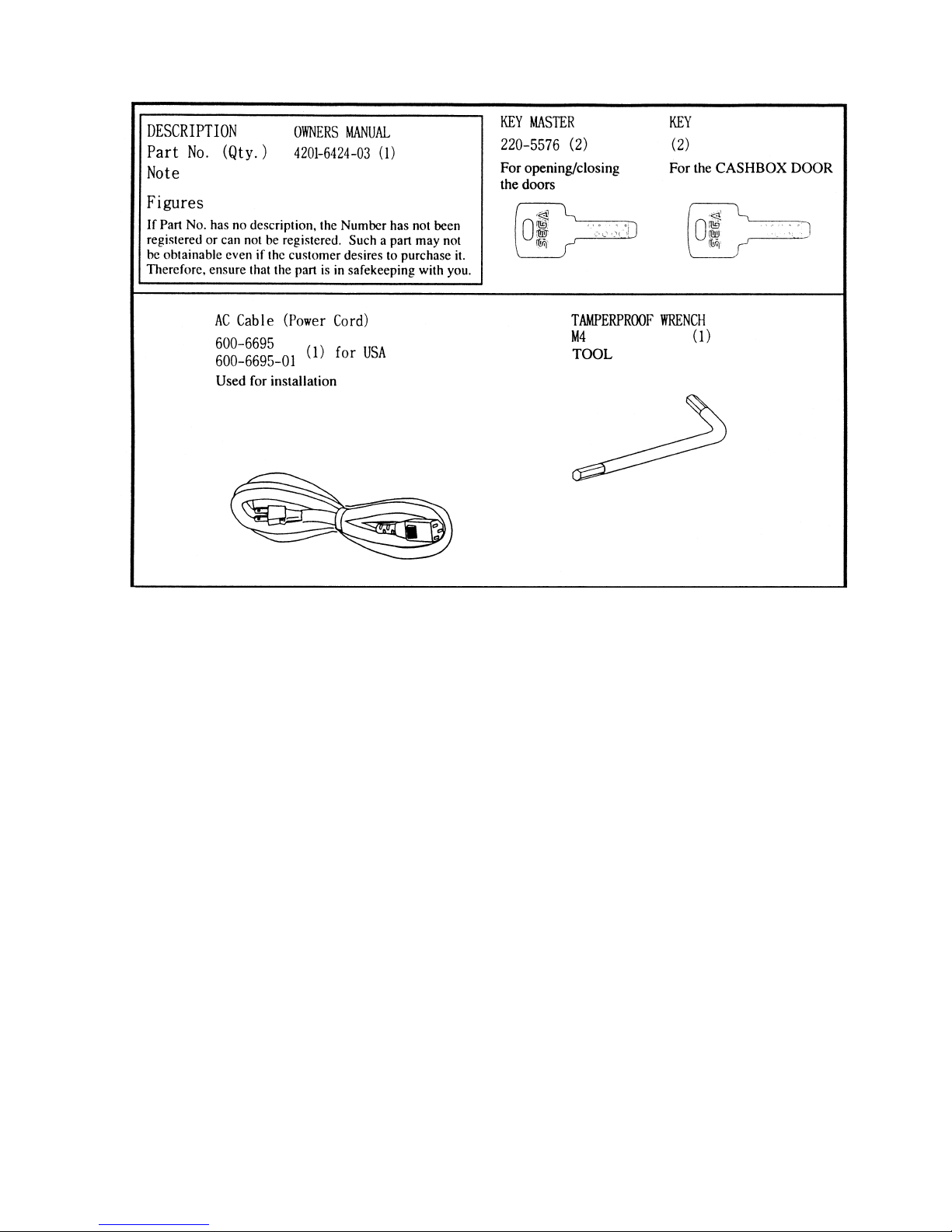
5. ACCESSORIES
5

THE SHIPMENT METHOD DESCRIBED BELOW ONLY
APPLIES TO ‘MODEL 3’ AND ‘NAOMI’ BOARDS
CONTAINED IN THE FOLLOWING GAMES:
LOST WORLD, VIRTUA FIGHTER 3, SUPER GT, SEGA BASS FISHING, STRIKER 2
HARLEY DAVIDSON, RALLY 2, DAYTONA 2, DIRT DEVILS, THE OCEAN HUNTER,
STAR WARS TRILOGY, HOUSE OF THE DEAD 2
!!NEVER SHIP MODEL 3 AND/OR NAMOI
!!NEVER SHIP MODEL 3 AND/OR NAMOI
GAME BOARDS OUTSIDE OF CAGE!!
GAME BOARDS OUTSIDE OF CAGE!!
CARTON BOX
601-8928 (1)
Used for transporting the GAME BOARD.
{SUPPLIED WITH YOUR GAME}
DO NOT SHIP GAME BOARD WITHOUT
THIS BOX AS IT MAY DAMAGE THE GAME
BOARD AND VOID YOUR W ARRANTY.
“CHECK SIDE” Display
FILTER BOARD
NO OTHER GAMES BOARDS ARE TO BE SHIPPED IN THE CAGE AS
THEY MAY BE DAMAGED BEYOND REPAIR. PLEASE SHIP THEM
WITHOUT CAGE PROPERLY PROTECTED DURING SHIPPING.
6
- 9 -
3. ASSEMBLING PRECAUTIONS
Assembling should be performed as per this manual. Since this is a
complex machine, erroneous assembling may cause damage to the
machine, or malfunctioning to occur.
When assembling, be sure to perform work by plural persons.
Depending on the assembly work, there are some cases in which
performing the work by a single person can cause personal injury or
parts damage.
When carrying out the assembly work, follow the procedure in the following 4-item sequence:
1
INSTALLING THE BILLBOARD PLATE
SECURING IN PLACE
2
POWER SUPPLY
3
4
ASSEMBLING CHECK
Note that the tools such as a phillips screwdriver and wrench for M16 hexagon bolt w/24 mm width
across flats are required for the assembly work.
7
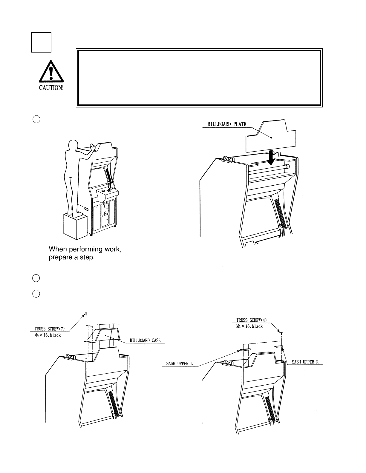
INSTALLING THE BILLBOARD PLATE
1
Installing the Billboard by one person is difficult. Be sure to use
plural persons to perform the work safely and accurately.
To perform work safely and securely, be sure to prepare a step
which is in a stable and secure condition. Performing work without
using a step can cause a viloent falling down accident.
Insert the BILLBOARD PLATE as shown.
1
2
Install the BILLBOARD CASE with 7 screws.
3
Install the SASH UPPER L & R with 4 screws.
8
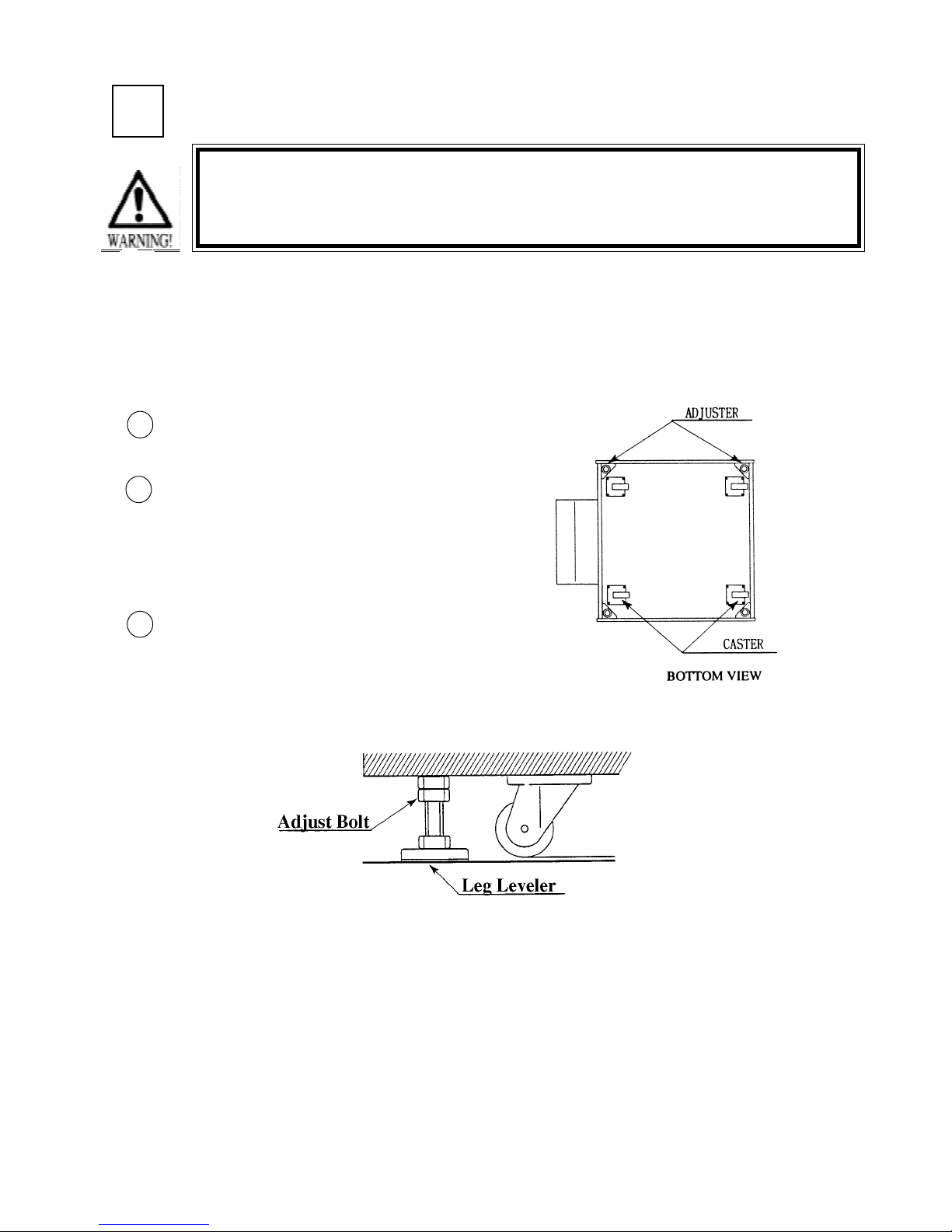
SECURING IN PLACE (ADJUSTER ADJUSTMENT)
2
Be sure to have all the Adjusters make contact with the floor surface.
Unless the Adjusters come into contact with the surface, the Cabinet
can move of itself, causing an accident.
This machine has 4 each of casters and adjuster (See Below). When the installation position is
determined, cause the adjusters to come into contact with the floor directly, make adjustments in
a manner so that the casters will be raised approximately 5mm. from the floor and make sure that
the machine position is level.
Move the machine to the installation
1
position.
Cause all of the leg adjusters to make
2
contact with the floor. By using a
wrench, make adjustments in the height
of the leg adjusters to ensure that the
machine's position is level.
After making adjustments, fasten the
3
leg adjuster nut upward and secure the
height of the leg adjuster .
9
3
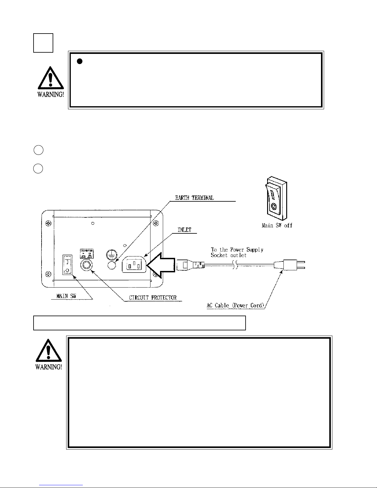
POWER SUPPLY
Ensure that the power cord is not exposed on the surface (passage,
etc.). If exposed, they can be caught and are susceptible to damage.
If damaged, the cord can cause an electric shock or short circuit.
Ensure that the wiring position is not in the customer's passage way
or the wiring has protective covering.
The AC unit is mounted on the left side of Front Cabinet DX. The AC Unit incorporates the Main
SW. Firmly insert the Power Plug into the Socket Outlet. Turn the Main SW ON to turn power
ON.
1
Ensure that the Main SW is OFF.
2
The AC unit is located on the left
side of the Cabinet. The Ac unit
incorporates the Main SW, and
power cord.
CAUTIONS TO BE HEEDED WHEN TURNING THE POWER ON
First make sure that no one is in the periphery of the bike body and turn
the Main SW on. When the power is turned on, the bike body motion
starts automatically. The presence of a person(s) in the periphery of the
bike can cause an accident. Turning the AC Unit’s Main SW on will cause
the machine to start the POWER ON check automatically. In the POWER
ON check, the bike body banks left and right, then returns to the centering position and stops. During this check, do not touch the bike body. If
you do, the body reaction (at the time course-out or crashing) can not be
obtained correctly. The Advertise mode is displayed at the same time the
checking is finished. An ERROR display is indicated if irregularity is found
in the POWER ON check. In case of an irregular reaction during game,
turn power off and turn it back on again to finish the POWER ON check.
10
4
In the TEST MODE, ensure that the assembly has been made correctly and IC BD is satisfactory
(refer to Section 6).
In the test mode, perform the following test:
ASSEMBLING CHECK
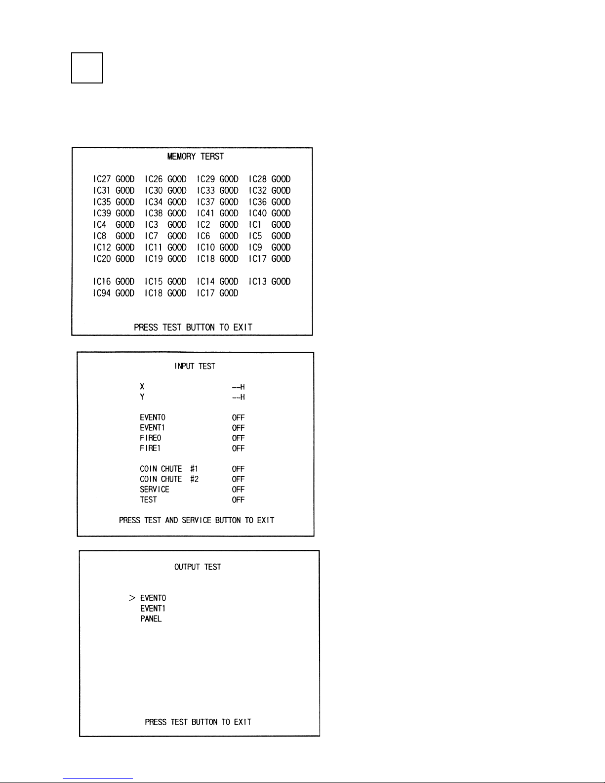
Selecting the MEMORY TEST on the test
mode menu screen causes the on-board
memory to be tested automatically. The game
board is satisfactory if the display beside each
IC No. shows GOOD.
Selecting the INPUT TEST on the test mode
menu screen causes the screen (on which each
switch is tested) to be displayed. Press each
switch. For the coin switch test, insert a coin
into the coin inlet with the coin chute door
being open. If the display beside each switch
indicates "ON," the switch and wiring connections are satisfactory.
11

In the TEST mode, selecting SOUND TEST
causes the screen, on which sound related BD
and wiring connections are tested, to be
displayed. be sure to check if the sound is
satisfactorily emitted from each of speaker and
the sound volume is appropriate.
In the TEST mode menu, selecting C.R.T.
TEST allows the screen (on which the monitor
is tested) to be displayed. Although the monitor
adjustments have been made at the same time
of shipment from the factory, color deviation,
etc., may occur due to the effect caused by
geomagnitism, the location building’s steel
frames and other game machines in the periphery. By watching the test mode screen, make
judgement as to whether an adjustment is
needed. If it is neccessary, adjust the monitor
by refering to Section 9.
12
4. PRECATIONS TO BE HEEDED WHEN MOVING THE MACHINE
When moving the machine, be sure to pull out the plug from
the power supply. Moving the machine with the plug as is
inserted can damage the power cord and cause a fire or electric shock.
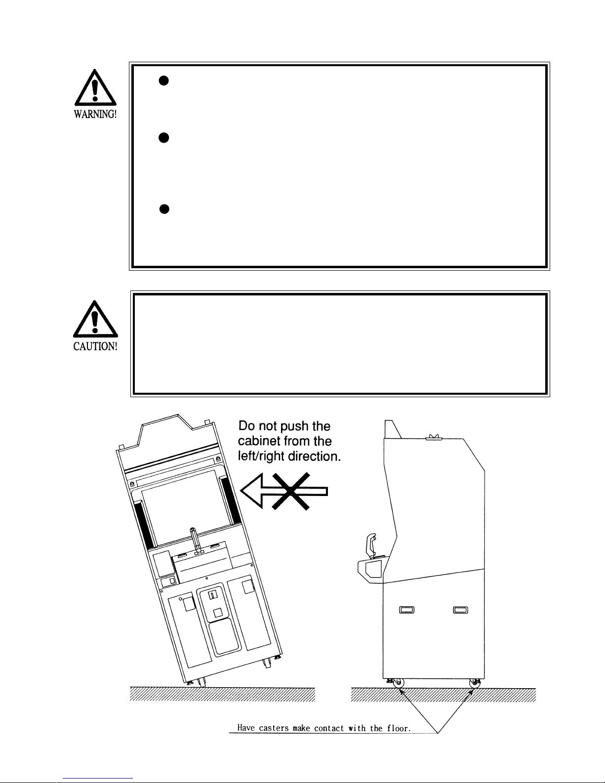
When moving the machine on the floor, retract the Adjusters
and ensure that Casters make contact with the floor. During
transportation, pay careful attention so that Casters do not
tread power cords. Damaging the power cords can cause an
electric shock and/or short circuit.
When lifting the cabinet, be sure to hold the catch portions or
bottom part. Lifting the cabinet by holding other portions can
damage parts and installation portions, due to the empty
weight of the cabinet, and cause personal injury.
Since this machine is a heavy structure of approximately 1000+lbs.
its leg adjusters should be retracted when moving the machine over
the floor. When moving the machine on the floor with slanted surfaces or step like differences, ensure that the PTV, Front Cabinet
and Rear Base are seperated. Lifting the Cabinet with those items as
is joined can cause the joint portions to be damaged.
13
5. CONTENTS OF GAME
The following explanations apply to the case the product is functioning satisfactoriliy. Should there be any moves
different from the following contents, some sort of faults may have occurred. Immediately look into the cause of the
fault and eliminate the cause thereof to ensure satisfactory operation.
The left/right lamps inside the Control Panel light up during game only.
The EVENT/START button (red buton, one each on the left/right side of LEVER) lights up in particular screens
only.
1
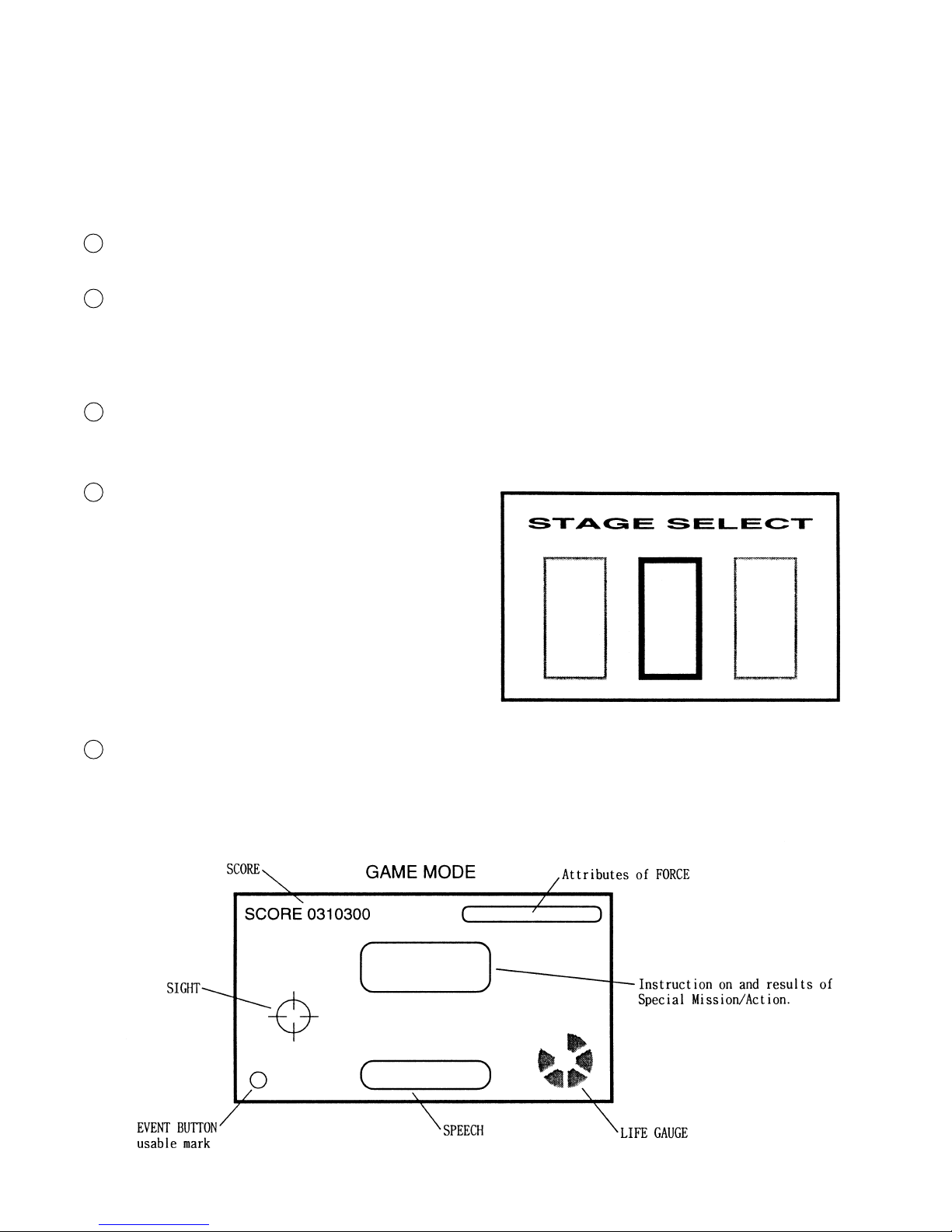
After inserting one play worth of coin(s), press the EVENT/START button to start, and the STAGE SELECT screen
appears.
2
At the time of starting the game, only the 3 stages, i.e., “YAVIN,” “HOTH,” and “ENDOR FOREST” are displayed.
By moving the LEVER left/right, select one from among the 3 stages and pull the trigger to decide. (execute the
selection).
NOTE: The player’s flight machine used during game is predetermined per STAGE.
After the STAGE is determined, the still screen for loading the game data appears for several seconds (this cannot
3
be skipped). Next, Movie Demo based on that particular STAGE’s story setting appears for several seconds (this
can be skipped by using the EVENT button).
Move the SIGHT by moving the LEVER up/down and left/
4
right, aim at the target and press either the trigger with the
forefinger or the thumbs switch with thumb to attack (the
function of the trigger at the position corresponding to the
forefinger and that of the Thumb SW. at the position
corresponding to a thumb identical). It is not necessary to
operate the flight machine. In the stage where the player
fights while boarding the flight machine, he can continually shoot by keeping the trigger pressed.
The up/down movements of the SIGHT as against the up/
down movements of LEVER can be set oppisite each other
within the TEST mode.
During game, instruction on Special Mission/Action or hints on play may be displayed at the center of the screen.
5
The player can obtain good results by following the instruction.
During game, SPEECH sound may be emitted on the lower part of the screen. Although hints on play are included
sometimes, basically the SPEECH expressions are intended for presentation effects and do not affect game proceeding.
14
If the LIFE GAUGE on the lower right side of the screen is depleted, on-screen movements stop and CONTINUE
6
YES or NO is questioned. to continue, insert the necessary number of coins, select YES by moving the LEVER left/
right, and then press the EVENT/START button. In case the count becomes 0 (zero), or if NO is selected and
EVENT /START button is pressed, continue play is not possible. If CONTINUE is not selected, the present on-stage
results are displayed, then the game is over.
(On the still screen for CONTINUE confirmation, the background of screen may become red sometimes, but this is
only for presentation effects shown momentarily at the time of being subject to damage and does not mean any
irregularity. The status will be restored to the normal background at the same time game restarts.
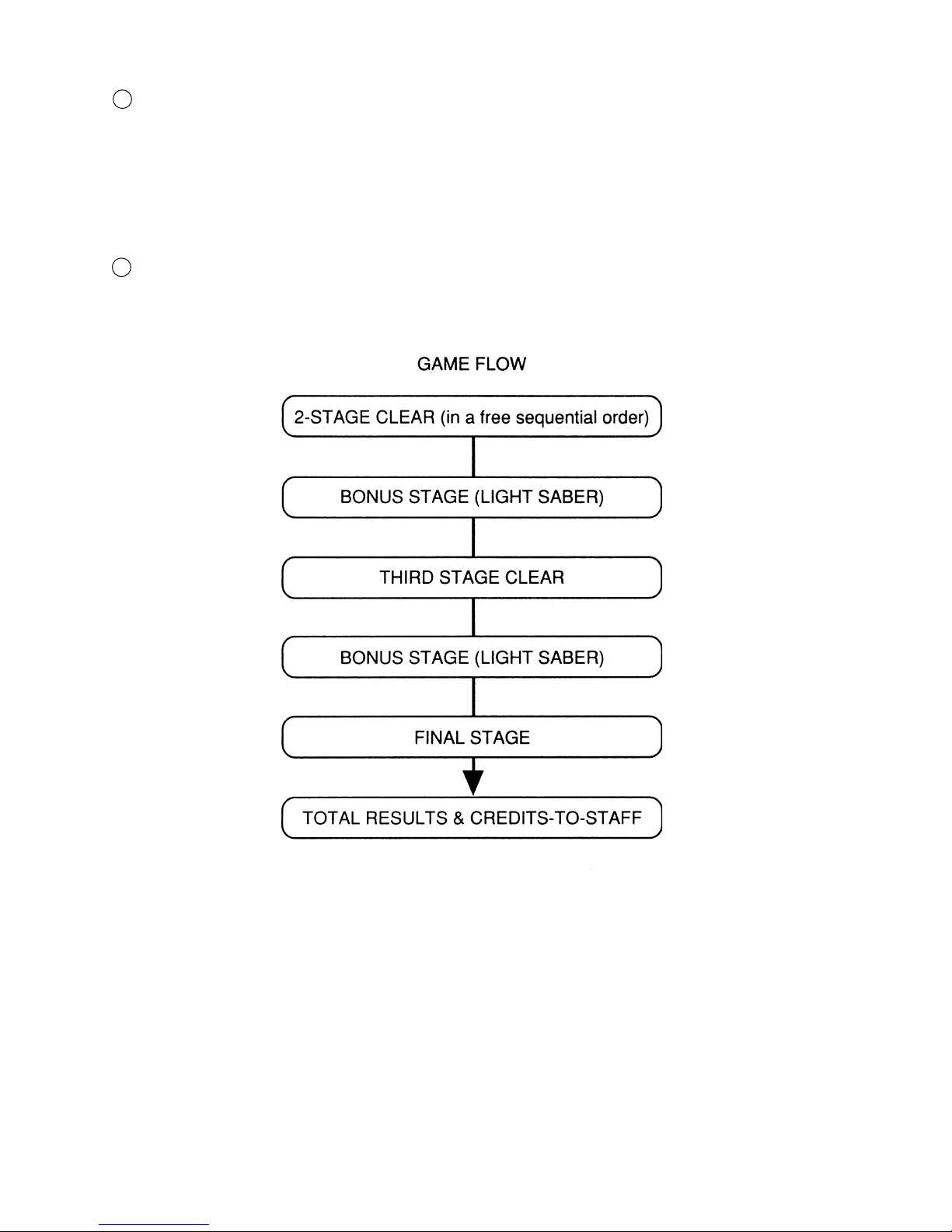
If all of the 3 STAGES shown at first in the STAGE SELECT screen are cleared, the 4th (FINAL) stage appears.
7
When all of the above stages are cleared, game results are shown and then credits-to-staff are displayed. Credits-tostaff can skipped by using the EVENT/START button.
15
EVENT BUTTON
In a specific scene, the on-screen message may insruct you to press the EVENT button. Press
either the left/right EVENT buttons as these have the same function.
Even when no particular insruction is given, if a mark is indicated on the lower left side of the
screen, or when the Cabinet’s EVENT buton is lit, some sort of effects can be obtained (for
example, a covering fighter appears) by pressing the button. The type of the effects differs
depending on the specific scene and stage.
There will be no adverse effect on the proceeding of game play if the button is not pressed.
This feature is intended for enabling the player to enjoy playing the game better.
ATTRIBUTES BUTTON
The features of FORCE vary in 6 catagories depending on the actions taken during the game,
and influence the performance of score, attack, and defense. Taking actions favorable to friends
(by saving them for example) causes LIGHT LEVEL to vary from 1 up to 3. On the contrary,
doing things unfavorable to friends (by attacking them for example) causes DARK LEVEL to
vary from 1 up to 3. The conditions of variation are not displayed in details. The features are
intended to allow players to enjoy playing game fully in depth.
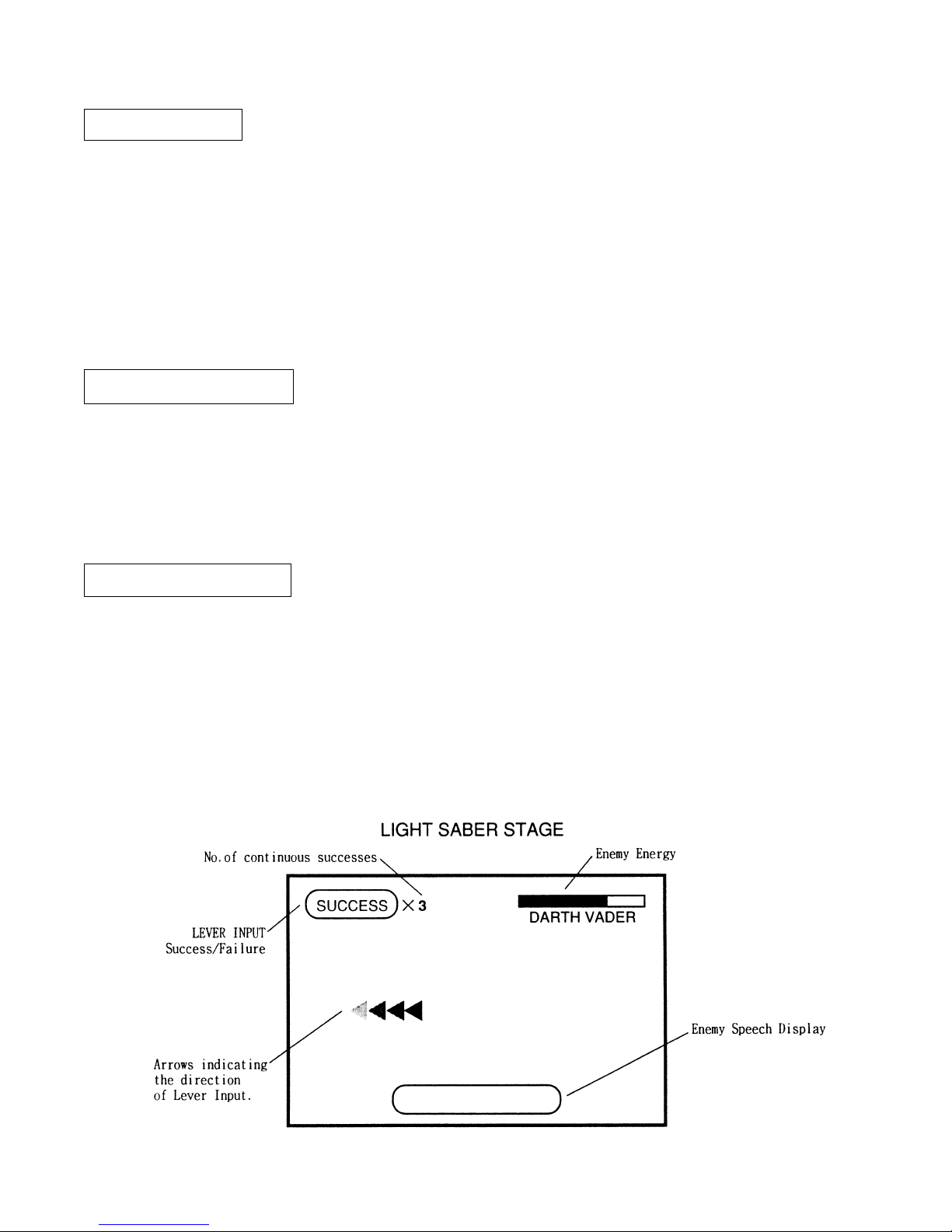
LIGHT SABER STAGE
In the LIGHT SABER STAGE (a breif stage in which the player uses a LIGHT SABER), keep
inputting the Lever in the direction of the on-screen arrow to proceed with game play.
This is completely a BONUS STAGE and there will be no game over in the middle of play.
The LIGHT SABER STAGE appears once when 2 of the 3 stages are cleared in a free sequential order, and once again when the remaining stage is cleared. (Not displaying at the time of
game start).
16
6. EXPLANATION OF TEST AND DATA DISPLAY
By operating the switch unit, periodically perform the tests and data check. When installing
the machine initially or collecting cash, or when the machine does not function correctly,
perform checking in accordance with the explanations given in this section. The following
shows tests and modes that should be utilized as applicable.
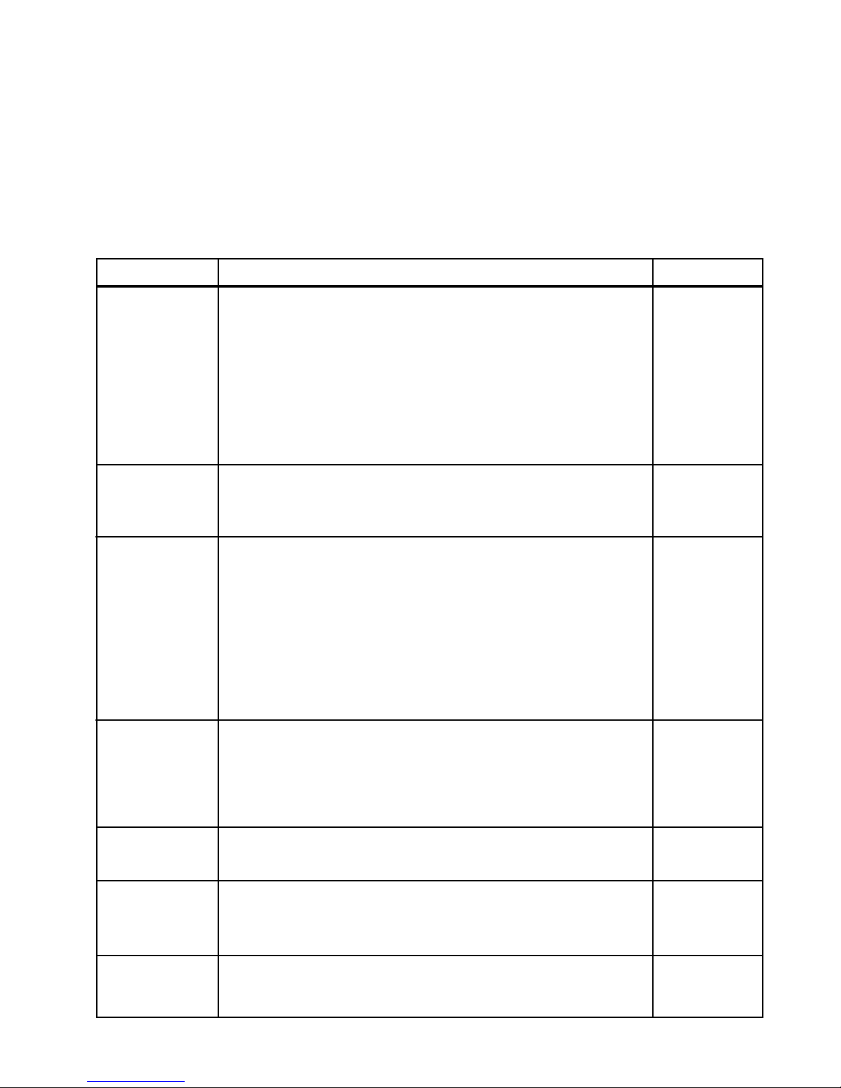
TABLE 6 EXPLANATION OF TEST MODE
ITEMS DESCRIPTION SECTIONS
When the machine is installed, perform the following:
INSTALLATION
OF MACHINE
MEMORY
PERIODIC
SERVICING
1. Check to see that each setting is as per standard setting made
at the time of shipment.
2. In the INPUT TEST mode, check each SW and VR.
3. In the OUTPUT TEST mode, check each of lamps.
4. In the MEMORY TEST mode, check ICs on the IC Board.
Choose MEMORY TEST in the MENU mode to allow the
MEMORY test to be performed. In this test, PROGRAM
RAMs, ROMs, and ICs on the IC Board are checked.
Periodically perform the following:
1. MEMORY TEST
2. Ascertain each setting.
3. In the INPUT TEST mode, test the CONTROL device
4. In the OUTPUT TEST mode, check each of the lamps.
6 - 8, 6 - 9,
6 - 10
6 - 4
6 - 7
6 - 3
6 - 3
6 - 3
6 - 8, 6 - 9
6 - 4
6 - 7
CONTROL
SYSTEM
MONITOR
IC BOARD
DATA CHECK
1. In the INPUT TEST mode, check each SW and VR.
2. Adjust or replace each SW and VR.
3.If the problem hasn’t been solved yet, check the CONTROL’s moves.
In the MONITOR ADJUSTMENT mode, check to see if the
PROJECTOR adjustment is appropriately made.
1. MEMORY TEST
2. In the SOUND TEST mode, check the sound related ROMs.
Check such data as game play time and histogram to adjust the
difficulty level, etc
6 - 4
7
7
9
6 - 3
6 - 5
6 - 11
17
 Loading...