

Page 1
(CEC version)
SEGA AMUSEMENTS U.S.A., INC.
800 Arthur Avenue. Elk Grove Village, IL 60007-5215
Phone: 888-877-2669 FAX: 847-427-1065
Page 1
Page 2

Table of Contents
1. Safety Notices …………………………………………………………………………………………………………………………………..2
2. FCC Compliance …………………………………………………………………………………………………………………….2
3. Setting-up the Game for the Desired Payout Percentage ……………………………………………………………3
3.1. Coins-per-Credit (service menu setting 02) ........................................................... 3
3.2. Prize Dial (service menu setting 03) ........................................................................ 3
3.3. Skill Level (service menu setting 06)...................................................................... 3
4. Service Menu: …………………………………………………………………………………………………………………………………..4
5. SONIC SPINNER ERROR CODES ………………………………………………………………………………………………………6
6. SONIC SPINNER SWITCH & OUTPUT NUMBERS ………………………………………………………………………….7
7. Parts and Part Numbers …………………………………………………………………………………………………………………….8
7.1. Exploded Drawing of Mechanism with Part Numbers......................................... 8
7.2. Main Cabinet with Parts Numbers............................................................................ 9
8. Wiring Schematic …………………………………………………………………………………………………………………..10
1. Safety Notices
The following safety instructions apply to all game operator s. We recommend that you read this page before
setting-up SONIC SPINNER. Use the following safety guidelines to help protect the system from potential
damage and to ensure your personal safety.
• Use with only 120 volts/60Hz
• To help prevent electric shock, plug the system power cables into properly grounded power sources. These
cables are equipped with 3-prong plu gs to help ensure proper grounding. Do not use ada pte r pl u gs o r
remove the grounding prong from a cable. If you must use an extension cable, use a 3 wire cable with
properly grounded plugs.
• To help protect your system from sudden, transient increases and decreases in electrical power, use a surge
suppressor, line conditioner or uninterruptible power supply (UPS).
• Do not spill food or liquid on your system.
• Do not push any objects into the openings of th e system. Doing so can cause fire or electric shock by
shorting out interior components.
• Keep your game far away from radiators and heat sources.
• Do not block cooling vents.
• Before working on the machine be sure to unplug it.
• Be sure to use fuses that meet the specified rating. (5A, 250V Fast-blow). Using fuses exceeding the
specified rating can cause a fire and electrical shock.
2. FCC Compliance
Note: This equipment has been tested and found to comply with the limits for a Class A digital dev ice, pursuant
to Part 15 of the FCC Rules. These limits are designed to provide reasonable protection against harmful
interference when the equipment is operated in a commercial environment. This equipment generates, uses, and
can radiate radio frequency energy and, if not installed and used in accordance with the instructions manual,
may cause harmful interference to radio communications. Operation of this equipment in a residential area is
likely to cause harmful interference in which case the user will be required to correct the interference at his own
expense.
Page 2
Page 3
3. Setting-up the Game for the Desired Payout Percentage
There are three settings that affect the game’s payout percentage; the Coins-Per-Credit setting, Prize Dial
setting, and the Skill Level setting. See Section 4 for information on how to enter and change settings in
the Service Menu.
3.1. Coins-per-Credit (service menu setting 02)
This setting determines the number of coins that have to be inserted before a single play is initiated.
SONIC SPINNER can be set from one to nine coins per single play. The game’s default setting is one
coin per play.
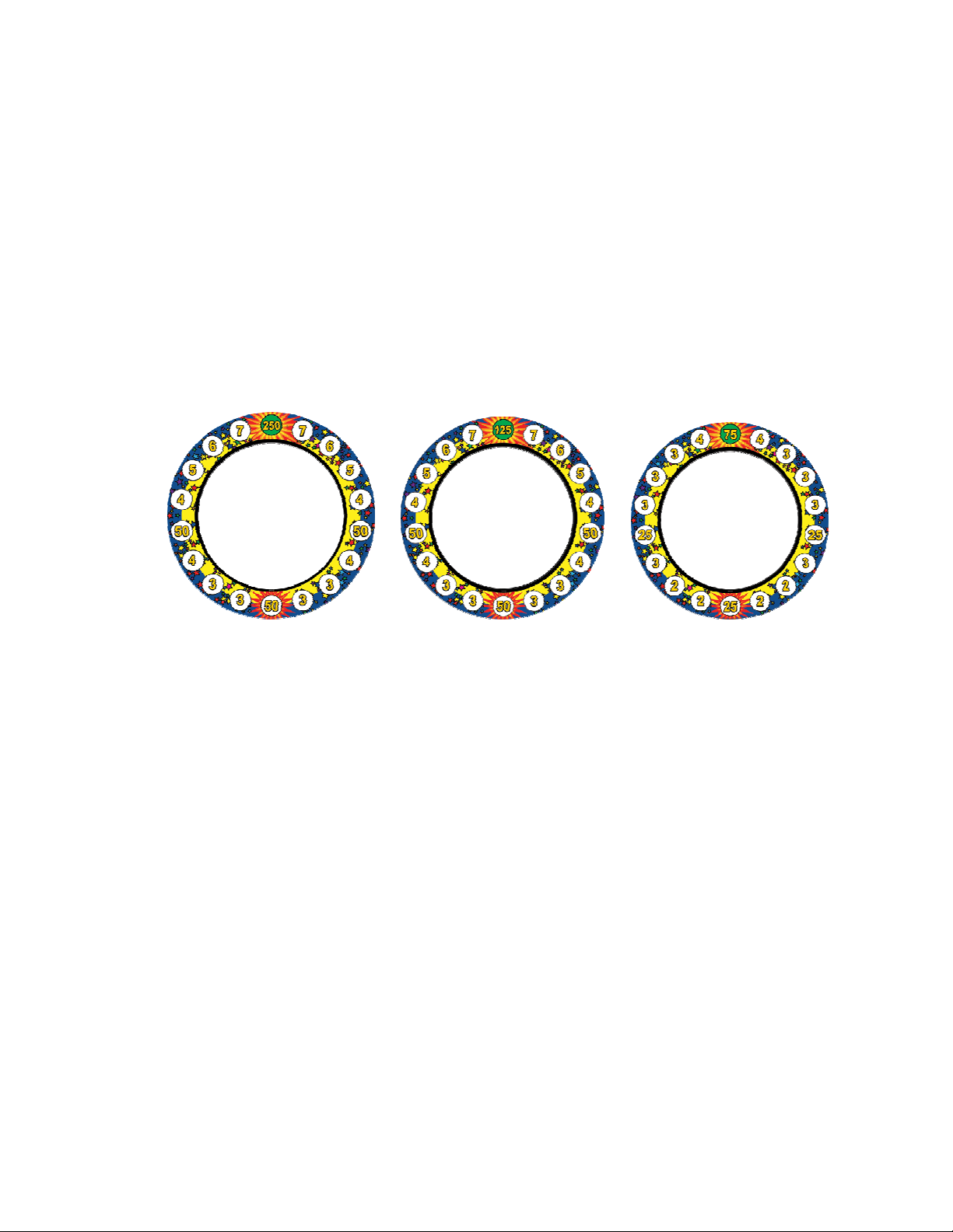
3.2. Prize Dial (service menu setting 03)
SONIC SPINNER ships with three unique Prize Dials. Use the Prize Dial to get close to your desired
ticket payout and then tune the payout by adjusting the Skill Level setting up or down.
Prize Dial #1 Prize Dial #2 Prize Dial #3
High Medium Low
Average 15 tickets Average 7 tickets Average 4 tickets
At skill setting #4 At skill setting #6 At skill setting #6
Part#: 532-30-207 Part#: 532-30-206 Part#: 532-30-205
(PRIZE DIAL, DIAMOND) (PRIZE DIAL, CLUB) (PRIZE DIAL HEART)
3.3. Skill Level (service menu setting 06)
The skill level setting has nine increments and can be set from the easiest setting of “1” to the most
difficult setting of “9.” The skill settings will significantly affect the average ticket payout. Because
players vary at different locations, operators will need to monitor ticket payout and adjust the
difficulty level until they achieve the desired payout.
Page 3
Page 4
4. Service Menu:
The Service Menu allows operators to adjust game settings and test lamps, switches and the motor. The list of
service menu items and settings starts on the next page.
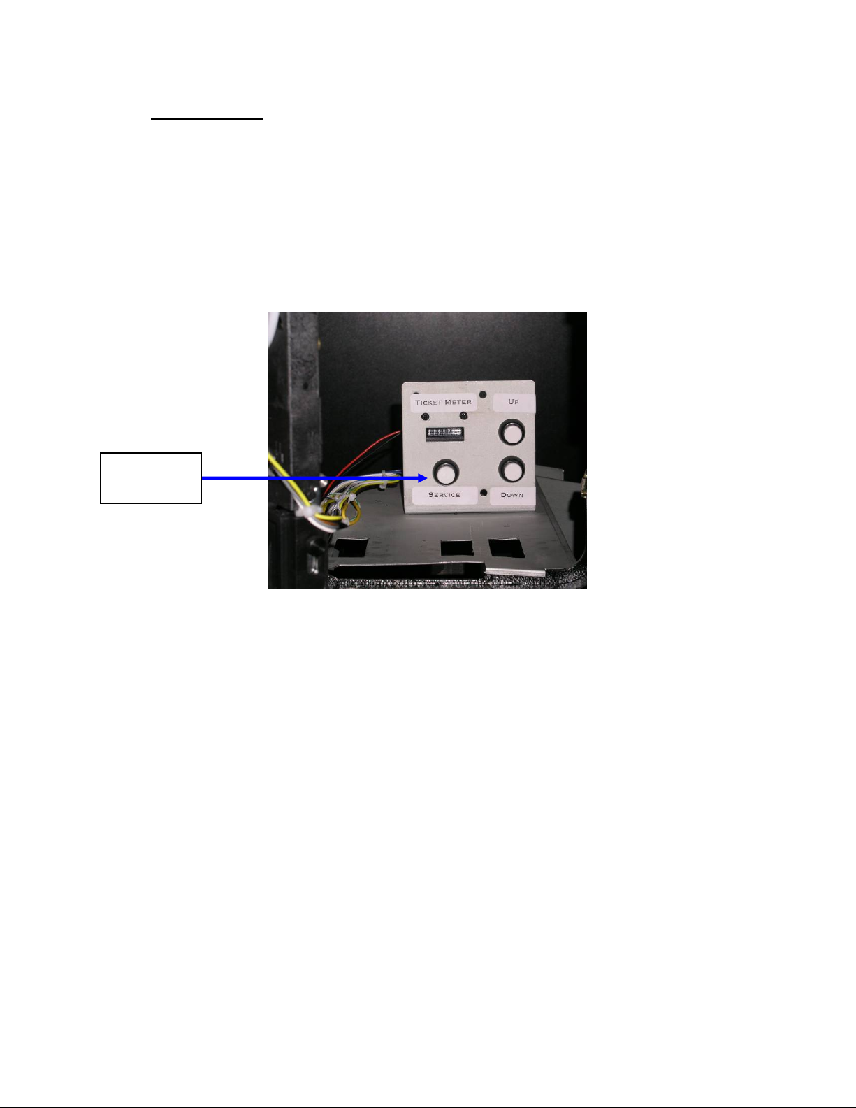
The Service Menu buttons are located behind the top coin door. Press the “Service” button to enter the Service
Menu. Once in the Service Menu, press the “Service” button again to advance to the next Service Menu item.
Service Menu items are adjusted by using the “Up” and “Down” buttons.
To exit the Service Menu and save setting, press the “Service” button for three seconds.
“Service”
Button
Page 4
Page 5

SONIC SPINNER, SERVICE Menu Items
Service
Menu
Item
Configuration/
Test Name
01 Pay Mode 0 – Pay-for-Play 0 – Pay-for-Play
02 Coins-per-Credit 1 Coin / Credit 1 – 9 coins per Credit
03 Prize Dial
Setting
04 Attract Mode 2 – Sounds, Lights
06 Skill Level 6 - l 1 – Easy
19 Bill Acceptor 0 – none installed 0 – no Bill Acceptor Installed
30 Clear Credits n/a Clears accumulated credits
40 Switch Test n/a Shows switch number of any switch (including INDEX and SECTOR
41 Lights Test n/a Use UP and DOWN switches to turn the various non-prize dial lights
42 Prize Dial
Lamps Test
43 Display Test n/a Use UP and DOWN switches to turn display ON and OFF. When ON,
44 Motor Test n/a Use UP and DOWN switches to turn motor ON and OFF.
45 Sound Test n/a Use UP switch to exercise Sound Channel 1. Use DOWN switch to
46 Ticket Dispenser
Test
98 Restore Factory
Defaults
Factory Default
Value
2 – Medium 1 – Prize Dial #1 - High
& Motion
n/a Use UP and DOWN switches to sequentially turn Prize Dial Lamps
n/a Depressing the DOWN switch will dispense 1 ticket. UP dispenses 5
0 – keep current
values
Menu Item Values & Description
1 - Free-Play (Show/Demo) with NO Tickets Dispensed
2 – Prize Dial #2 - Medium
3 – Prize Dial #3 - Low
0 – No attract mode
1 – No Sound
2 – Sounds, Lights & Motion
2 –
3
4 –
5 - Normal
6
7 - Hard
8 -
9 – Extremely Hard
1 – 9 Coins counted for each dollar
(assumes 1- active LOW pulse per dollar)
Optos) that is found to be “ON”. Values range from 00 – 31. A list of
switch numbers can be found in Section 6.
ON and OFF. See Test 42 below for Prize Dial Lamps Test.
ON. UP turns Lamps on in a Clockwise direction, DOWN in a
Counter-Clockwise direction. The LED display shows the Sector
Number of the Lamp currently ON. Sector Numbers start at 12
o’clock == Sector 1.
the display shows ‘all eights’ 888
exercise Sound Channel 2
tickets. The Ticket Meter is not advanced during this test.
0 – keep current values
1 – Factory Default Configuration
Page 5
Page 6

5. SONIC SPINNER, ERROR CODES
The 3-digit display is used to show error codes during the calibration sequence, and during
game play. For most errors, the actual ERROR CODEs (numbers from 00 – 99) are shown
on the display. Errors detected during the Power-Up/Calibration sequence are displayed
with a “C” on the display then the Error Number. Errors detected during game play are
shown with “E” on the display and then the error code. The “C” and “E” arrangement allows
the operator to know if the problem was detected on Power-Up/Calibration before the game
play started, or was encountered during actual game play.
A couple of special “errors” are shown in an alpha-only format rather than the alphanumeric
format described above. Ticket errors are shown with “tic”, and coin switch errors are shown
as “Coi”. These relatively common "errors" are more easily identified with an alpha format.
ERROR CODES
Error # Problem Area
00
Stuck Switch A normally OFF switch was
through
31
“tic”
“Coi”
Ticket Dispenser If a ticket notch is not
Coin Switch One (or both) coin switches
Problem Detail Possible Causes Action to Reset
Error Code
detected as ON.
detected, the ticket
dispenser is turned on for 3
seconds to search for the
notch. If notch is not found
this error is displayed.
Note: Detection of this error
is DISABLED when in
“Show/DEMO” mode
were detected “ON”
(1) Bad switch
(2) Shorted cable
(1) Ticket Jammed
(2) Bad Ticket
Dispenser/Opto
(1) Coin is stuck
(2) Bad Switch
(3) Shorted Cable
Determine which
switch is the problem
by locating it on
schematic. The Error
Code corresponds to
the SWxx number in
Section 6. Fatal
Error – Game will not
continue.
Remove jammed
ticket, change Ticket
Dispenser. Fatal
Error – game will not
continue.
Remove jammed
coin. Fatal Error –
Game will not
continue.
Page 6
Page 7

SONIC SPINNER, SWITCH & OUTPUT NUMBERS
The following table summarizes the SONIC SPINNER Switch Numbers (SWxx) that can appear as part of the
Error Code for a stuck switch. Also included for reference are Output Numbers (OP#). The Switch and Output
numbers correspond to references as shown on the SONIC SPINNER Schematic. Unused Switch and Outputs
numbers are shown as ‘-----‘
SW #
00 Player Stop SW 0 Player Stop Lamp
01 Index Opto 1
02 Sector Opto 2
-----
03
-----
04
-----
05
-----
06
-----
07
-----
08
-----
09
-----
10
-----
11
-----
12
-----
13
-----
14
-----
15
16 Service - START 16 Tickets LOW Lamp
17 Service - UP 17
18 Service - DOWN 18
19 Tickets LOW SW 19 Ticket Motor Enable
20 Bill Acceptor Pulse 20 Coin-In Counter
21 Coin-In Left 21 Tickets Paid Counter
22 Coin-In Right 22
23 Ticket Notch 23
-----
24
-----
25
-----
26
-----
27
-----
28
-----
29
-----
30
-----
31
OP#
-----
-----
-----
3
4 Display Tickets Lamp
5 Display Credits Lamp
-----
6
-----
7
-----
8
-----
9
-----
10
-----
11
-----
12
-----
13
-----
14
-----
15
------
-----
-----
-----
-----
24
-----
25
-----
26
-----
27
-----
28
-----
29
-----
30
-----
31
Page 7
Page 8

6. Parts and Part Numbers
6.1. Exploded Drawing of Mechanism with Part Numbers
Page 8
Page 9

6.2. Main Cabinet with Parts Numbers
Led Light for Marquee
Part#: PL16N-WDW-15Z
Speaker Grill (x2) S.SPNR 07
(Color: Blue )
Part#: SBJ-MLS-SPKGRIL
Marquee S.Spnr 07
Part#: 538-30-100
Spinning Sonic Disk,
S.SPNR 07
Part#: 538-30-208
Front Plexi Clear, S.SPNR 07
Part# 538-30-215
Control Panel Overlay
S.SPNR 07
Part#: 538-30-150
Front panel decal,
S.SPNR 07
Part#: 538-30-200
DECAL BASE RIGHT, S.SPNR 07
Part# 538-30-202
DECAL BASE LEFT, S.SPNR 07
Part# 538-30-201 (OTHER SIDE)
Display Plate Credit/Ticket
S.SPNR 07
Part#: 538-30-210
TICKET DOOR ASSY
Part#: 40-0038-04
(Part# of happ)
Page 9
Page 10

7. Parts and Parts number
Mechanism Assy
Play-field Lamp (18)
Model#: 1250x-2
NOTE: This is Xenon bulb.
CAN NOT USE Standard
Bulb!!!
F.L.Assy, Play-field
Part#: CAMUC115
(Part# of duray)
18”, 115vac
Speaker, 8 ohm, 25W (2)
Lamp Diode PCB
Part#:
SBS-PCB-LMPDIOD
3 digits DISPLAY BOARD
Part#: SBJ-PCB-3DPL23
Page 10
Page 11

Part#: MTR-455A103
Motor
Opto. Sensor Board
Part#: SBJ-PCB-WHLOPTO
(MODEL#: 350 5m 09)
Belt
Part#: 104-0050 (HAPP)
Main PCB
Ticket Dispenser
(Deltronics) MODEL#: DL-1275
CAPACITOR = NRSA222M25V
Power Supply
24VDC (5A)), 12VDC (5A)
Part#: UP-45 ot44-0600
Page 11
Page 12

3 digits DISPLAY BOARD
Part#: SBJ-PCB-3DPL23
Push button
Part#: 95-4002-15ZL
(Part# of HAPP)
Marquee Plastic (Black mold)
Note: Only cec model
Led Light for Marquee
Part#: PL16N-WDW-15Z
LED PCB Part#:560MW7D
For Technical Assistance and parts, please call
SEGA Amusements U.S.A., INC.
at (888)877-2669
Page 12
 Loading...