


1st Printing UK Version
TWIN TYPE
DEITH
025;>
LEISURE
SPARES
Before using
carefully to
After reading this manual, be sure
product or somewhere convenient in order to be able to refer to
Built In the UK
by
this
understand the contents stated herein.
Eo)
IMroRTANr!
product, read
it
whenever necessary.
this
to
k6GIl
"UEM8EROFmESCUGRooP
OWNERS
it available nearby the
MANUAL
420·6229-02UK


BEFORE
To ensure the safe usage of the product, be sure to read the following before using the
product. The following instructions are intended for the use of
only. After carefully reading and sufficently understanding the instructions, handle the
machine in an appropriate manner. Only qualified personnel should install or carry out
maintenance on the product.
Terms such as WARNING!, CAUTION I and IMPORTANT! are used where an explanation
is given which requires special attention, depending on the potential risk. SEGA is not
responsible, for any injury or damage caused by use in a manner contrary to the
instructions stated in this document. In order to prevent accidents, warning stickers and
printed instructions.are applied in the places where a potentially hazardous situation
relating to the product cuold arise. Be sure to comply with these warnings.
USING
THE
PRODUCT,BE
SURETOREAD
qualified
THE
FOLLOWING
service
personnel
WARNING!
Indicates that mishandling the product by
disregarding this warning will cause a
potentially hazardous situation which can
result in death or serious injury.
Indicates that mishandling the product by
disregarding this caution will cause a
potentially hazardous situation which can
result in personal injury and or material
damage.
CAUTION'
IMPORTANT!
This is cautionary information which should be complied with when handling the product.
Indicates that mishandling the product by disregarding this will cause a potentially
hazardous situation which Whilst it may not result in personal injury could damage the
equipment.
Be
suretoturn
the
machine.
Ensure
that
the
off
power
correct
and
disconnect
fuseisfitted
to the
from
the
machine.
mains
supply
before
working
on
Details of the correct fusing of the machine are enclosed in the Installation/Service Manual.
that
only
Ensure
Machine.
Specification
designated
conformity.
The parts of the product also include any Warning Labels or Safety Covers for personal
protection etc. A potential hazard will be created if the machine is operated
have been removed. Should any doors, lids or protective covers be damaged or lost, do
qualified Service Engineers
Changes (removal of
by SEGA are
not
permitted
equipment,
A
and
perform
conversion
will
invalidate
any
maintenance
and
this
addition)
products
workonthe
not
CE
While
any parts

not operate the product. SEGA is not liable in any way whatsoever for any injury and or
damage caused by Specification Changes (using other
designated by SEGA.
firms parts, or by conversion) not
Ensure
Before instailing the product, check for Electrical Specifications. SEGA products have a
nameplate on which Electrical Specifications are detailed. Ensure that the product Is
compatible with the power supply voltage and frequency requirements of the location in
which the machine is installed.
Install
allowing
To ensure maximum safety for both customers and operators, labels and printed
instructions describing potential hazardous situations are appiied to places where
accidents could occur. Ensure that where the product Is operated has sufficent lighting
allowing any warnings to be read. If any label is peeled off, replace it immediately.
When
Some of the Monitor (TV) parts are subject to high tension voltage. Even after turning off
the power some parts are still occasionally subject to high tension voltage. Monitor repair
and replacement should be performed by
In cases where commercially available monitors and printers are used only the contents
reiating to this product are stated in this manual. Some commerclaily available equipment
has functions and reactions not stated in this manual. Read this manual in conjunction with
the specific Instruction Manual of such equipment.
that
the
and
Operate the
warning
handling
productIsof
labelstobe clearly read.
the
Monitor,
appropriate
Product
in places
be very careful.
Electrical
where
(Applies
qualified
Specification.
appropriate
onlytothe
service
engineers only.
lighting
product
is available,
w/monitor).
• Descriptions herein contained may be subject to change without prior notification.
• The contents described herein are fully prepared with due care. however. should any questions
arise or errors be found. please contact SEGA.
INSPECTIONS
Normally, at the time of shipment, SEGA products are in a state allowing usage
immediately after transporting to the location. Nevertheless, an Irregular situation may
arise during transportation preventing this. Before turning on the power, check the
following points to ensure that the product has been transported safely.
• Are there any dented parts or defects (cuts, etc) on the external surfaces of the cabinet?
• Are Castors and Leg Adjusters present and undamaged.
• Do the power supply voltage and frequency requirements meet with the local supply.
• Are all wiring connectors correctly and securely connected? Unless connected in the correct
direction, connector connections can not be made successfully. Do not insert connectors
forcibly.
• Are
• Do power cords have any cuts or dents?
• Do the fuses used meet specified rating? Is the Fuse working correctly?
• Are such units as Monitors, Control equipment, IC BD, etc. firmly secured? Are all Earth
• Are all accessories available?
• Can all doors and lids be opened with the accessory Keys? Can doors and lids be closed firm?
alllC's
connected.
IMMEDIATELY
of each IC BD firmly inserted?
AFTER
TRANSPORTING
THE
PRODUCTTOTHE
LOCATION.
Wires
\
B

CONCERNING THE STICKER DISPLAY
CONCERNING WARNING
DISPLA 1 u
SEGA product has Stickers describing the product
manufacture No. (Serial No.) and Electrical
Specifications.
to contact for repair and for purchasing parts.
inquiring about or asking for repair, mention
When
the Serial No. and Name of Machine indicated on the
Sticker.
Identical machines could have different parts
depending on the date of production.
improvements and modifications might have
made after the publication of this Manual. In order to
meet the above situations, mention the Serial No.
when contacting the applicable places.
The
Also it has a Sticker describing where
Serial No. indicates the product register.
MSD,
been
SEGA
Labels
to or incorporated in the places where a potentially
hazardous situation can arise. The warning displays
are intended for accident prevention for the
customers and for avoiding hazardous situation
relating
are some portions in the Cabinet, which are subject to
high
caused only by touching. When
servicing
displays.
replacement work
performed by those technical personnel who have
knowledge of
For the
whose act runs counter to the warnings, as
effect thai he must stop the act.
product has warning displaysOnStickers,
and or printed instructions adhered / attached
to maintenance
tension voltage, etc. where accidents can be
work,
be very careful of the warning .
Especially, any complex repair and
electricity and technical expertise.
prevention of accidents, caution any customer
and
servicingwork. There
performing the
not mentioned herein, should be
to the
AWARNlNG
~
\Ii
t¥~
~"""'>Mcl-
l_erJt,...-~
""""'-
44
__
O-lISOOO2XEG
SPECIFICATION
~
ELECTRICAL
DISPLAY
~I
I¥~I>W\""",,"
~
.......
...-.
T......
e«"......~
-.
440-WSOOO2XEG
During
g.&me
play,
be sure to take
• firm gnp of 1M
St..nngWh
440-CSOO11XEG
..
1.
NlNG
°rm
c

Installation Space:
SPECIFICATIONS
I640mm (64.6in) x 1700mm
(66.9in)
Height:
Weight:
Power, Max:
1920mm (75.6in)
480 kg
Rated Voltage:
Rated Current:
Rated Power
210
-
-4.0
4.6
970W
240
V.A.C
A
NOTE: Descriptions in this manual are subject to change without prior notice.
INTRODUCTION TO THIS OWNERS MANUAL
SEGA ENTERPRISES LTD., supported by its high electronic technologyofLSI's,
microprocessors, etc. and with a wealth
supplying various innovative and popular games to the world market. This Owners Manual is
intended to provide detailed descriptions together with all the necessary information covering
the general operation
parts, etc. as regards SEGA TOURING CAR TWIN, a new SEGA product. This manual is
intended for those who have a knowledge
IC's, CRT's, microprocessors, etc. Carefully read this manual to aquire sufficient knowledge
before working on the machine. Should there be a malfunction, non-technical personnel
should under no circumstances touch the interior systems. Should such a situation
immediately contact the nearest branch listed below or our head office.
of
electronic assemblies, electromechanicals, servicing control, spare
of
experience, has for more than 30 years been
of
electricity and technical expertise especially in
arise
. I
SEGA AMUSEMENTS EUROPE LIMITED / SEGA SERVICE CENTRE
Unit 2, Industrial Estate, Leigh Close, New Malden, Surrey, KT3 3NL, England
Telephone: +44(0)
Fax: +44(0)
SEGASPAIN
C/ PLAYA DE LIENCRES, 2-EDIFICIO 3 LONDRES,
EUROPA EMPRESARIAL CTRA, NATIONAL IV KM.24, 28230 LAS ROZAS (MADRID)
Telephone: +34(1) 6315000
Fax: +34(1) 6400689
181
336 2256
1813361715
D

CONTENTS
BEFORE USING THIS PRODUCT A
STICKER DISPLAY C
INTRODUCTION TO THIS OWNERS MANUAL D
I. HANDLING AND INSTALLATION PRECAUTIONS I
2. ACCESSORIES 2
3. NAME OF PARTS 3
4. ASSEMBLING THE CABINET 4
ASSEMBLING THE COCKPIT 4
SECURING IN PLACE 6
INSTALLING THE BILLBOARD 8
INSTALLIIiO THE AC COVERS 9
POWER SUPPLY 10
TURNING ON THE POWER 10
ASSEMBLY CHECK II
5. PRECAUTIONS WHEN MOVING THE MACHINE 13
6. THE GAME 14
7. EXPLANATION OF TEST AND DATA DISPLAY 16
VTS BRACKET 17
TEST MODE 19
MEMORY TEST 19
T.G.P. TEST 19
INPUT TEST 20
OUTPUT TEST 20
SOUND TEST 2I
C.R.T. TEST 21
GAME ASSIGNMENTS 22
COIN ASSIGNMENTS 22
BOOKKEEPING 26
BACKUP DATA CLEAR 27
8. MAINTENANCE 28
HANDLE MECHA MAINTENANCE 29
ACCELERATOR
& BRAKE UNIT MAINTENANCE 32
SHIFT LEVER MAINTENANCE 34
CHANGING THE VOLTAGE ON THE TRANSFORMER 35
FUSES 36
REPLACING THE FLOURESCENT LAMP AND LAMPS 37
PERIODIC INSPECTION TABLE 38
TROUBLESHOOTING 39
GAME BOARD
& DRIVE CONTROL BOARD 41
9. COMMUNICATION PLAY 45
10. PARTS LISTS 50
TOP ASSEMBLY STC-00002/3UK 50
BILLBOARD ASSEMBLY STC-0200UK 53
BILLBOARD UPPER ASSEMBLY STC·0210UK 54
BILLBOARD LOWER ASSEMBLY STC·0220UK 55
LAMP UNIT ASSEMBLY STC-0230UK 56
FLOURESCENT ASSEMBLY STC·0240UK 57
COINCHUTE TOWER ASSEMBLY DYN·0300UK 58
VTS ASSEMBLY DYN·0350UK 59
WIRE COVER ASSEMBLY DYN·0500UK 60
COCKPIT ASSEMBLY STC·IIOOIl2UK 61
CONTROL PANEL ASSEMBLY STC-12003UK 65
CONTROL PANEL COVER STC-1202-02 67
VIRTUAL BUTTON ASSEMBLY INY-1250 68

MONITOR HANDING KIT STC-7000UK 69
HANDING KIT STC·6000UK 70
MAIN BASE ASSEMBLY STC-2100IUK 72
BRAKE
& ACCELERATOR UN[T ASSEMBLY DYN-1300UK 74
FLOOR REAR ASSEMBLY DYN·2040UK 76
FLOOR FRONT ASSEMBLY MSB-2030UK 77
SEAT ASSEMBLY STC-2200UK 78
SEAT REAR COVER IP STC-1605 80
SEAT REAR COVER 2P STC-2202 81
WOOFER ASSEMBLY STC-1650 82
MAIN BOARD ASSEMBLY STC·4400 83
ELEC ASSEMBLY STC-4500UK 85
DRIVE CONTROL BOARD INY·4600 87
INSTALLATIONKIT STC·INST-KIT 88
II.
WIRE COLOUilCODE TABLE 89
12. SCHEMATICS 91
13. COIN MECH INSTALLATION AND CREDIT BOARD SETUP 93
14. DETAILS OF SANWA MONITOR [03
15. DETAILS OF NANAO MONITOR 126

1. HANDLING AND INSTALLATION PRECAUTIONS
When installing or inspecting the machine, be very carefulofthe following points and
pay attention to ensure that the player can enjoy the game safely.
This Game is designed for indoor use only. The game must
outdoors or under the following conditions:
I. In areas directly exposed to sunlight, high humidity, dust, excessive heat or
extreme cold.
2. In locations that would present an obstacle in the case
fire equipment or emergency exits.
3. On an unstable surface or subject to vibrations.
IMPORTANT.
This machine should only be installed by Qualified Service Personnel.
Ensure that the line voltage matches that
information see the section in this manual dealing with maintenance. Please note the
voltage that the machine has been set to during manufacture. This machine has been
set to 230V.
Be sure to switch the power
before replacing any user servicable parts.
Do
NOT
attempt to repair the PCB (printed Circuit Board) yourselfas this will void
the warranty. The PCB contains static sensitive components that could be damaged.
Always return a faulty PCB to your distributor with adequate packaging and
protection.
When removing the plug from a mains outlet always grasp the plug and not the cable.
Do not use a fuse that does not meet a specified rating.
Make sure all connections are secure before restoring power.
OFF
and remove the mains plug from the wall socket
of
the transformer input tapping for more
NOT
be installed
of
an emergency i.e. near
Ensure
there
Ensure
supply
that
is a
danger
that
without
the mains lead is not exposed.Ifthe
of an electric shockora
short
mains lead becomes exposed
circuit
the power supply is fitted with circuit protection. Using
circuit protection is a fire hazard.
1
the
power

2. ACCESSORIES
When Transporting the machine ensure that the following parts are supplied;
Part
Seq.
No.
1
2
3
4
5
6
7
8
9 RAL-XXXX-14UK
10
101 600-6275-0500
201 030-o00825-SB
202 FS1031
203
204
205 FX0400 M8 WSHR FORM A FLT BNP 12
206
207
208 FX0258 M8 WSHR
209 421-9141 STICKER CAR No
210 509-5704
401 DLMEMC17 CERT OF CONFORMANCE STCC 1
402 420-6229-02UK OWNERS MANUAL STCC
403 540-0006-01 WRENCH M4 TMP PRF 1
404 540-0007-01 WRENCH M5 TMP PRF
405 540-0009-01
406
407
409
Number
STC-0200UK
DYN-0300UK
DYN-0500UK
DYN-0013UK
DYN-0014UK
DYN-0006XUK
DYN-0018UK
DYN-0019UK
PK0087
030-000820-8 M8X20 BLT W/S PAS 4
000-P00408-WB M4X8 MSCR POSI PAN W/FS BNP 15
FX0011 M4 NUT FLG SER BZP 3
FS1031 M8 WSHR
220-5484 VOL CONT B-5K OHM
390-5167 LAMP 110V
OS1019
Description
ASSY BILLBOARD STCC UK
ASSY COIN CHUTE TOWER UK
ASSY WIRE COVER UK
JOINT PIPE
BILLBOARD HOLDER DAYTONA
ACCOVER
AC COVER C
'AC
COVER D
TIE BRACKET RALLY
CARTON INST KIT STCC
CABLE FIBER OPTIC 5mm x 500cm
M8X25 BLT W/S BNP
M8 WSHR
SW
MICRO TYPE (OMRON K3L 13) 1
WRENCH M8 TMP PRF
SELF SEAL BAG
B
l'MN
250D
FLT BNP
250D
FLT BNP 4
220D
FLT BZP 4
2-8
l'MN
30W
9X12.3/4
Qty.
1
1
1
1
2
1
1
1
1
1
2
16
4
1
1
1
1
1
2
1
(TAMPERPROOF
M5
S4O-OO11.{)1
M8
S4(}.OO()9.{)l.·
WRENCH)
~
TAMPERPROOF
WRENCH
2

3. NAME OF PARTS
29
INCH
llONITOR
BILLBOARD
COIN
CHUTE
IP
TOWER
COCKPIT
OVERVIEW
COIITROL
PANEL
2P
COCKPIT
BACK
LID
A
BACK
LID
B
AC
COVER
AC
UNIT
Width Length
COCKPIT (per seat)
COIN CHUTE TOWER
820
305
BILLBOARD 1,600
When assembled
1,632
X
X
X
X
Height
1,645
330
460
1,700
3
X
X
X
X
1,520
570
405
1,920
(mm.)
Weight (kg.)
231. 0
13.5
30.0
513. 0
\

4.
ASSEMBLING
THE
FAILING TO COMPLY
WHEN
ASSEMBLING THIS AMCHINE SOME
TO
COMPLETE
THE CA13INET
ASSEMBLY OF
ASSEMBLY
IN ORDER TO AVOID PERSONAL INJURY OR PARTS DAMAGE, BE SURE
THIS
MACHINE SHOULD ONLY BE CARRIED
WORK
SHOULD BE CARRIED OUT AS PER
WITH
THESE
INSTRUCTIONS MAY CAUSE AN
MALFUNCTION IN
ASSISTANCE BEFORE ATTEMPTING THESE OPERATIONS.
PERSONNEL.
OFTHE
THE
OPERATIONS
MACHINE.
OUT
THiS
ELECTRIC
REQUffiE
BY QUALIFIEDSERVICE
MANUAL.
MORE
SHOCK
HAZARD OR A
THAN ONE PERSON
TOP
SEEK
~
CAUTIONI
When
carrying OUI the assembly work, follow the procedure in the following 7-item
sequence:
ASSEMBLING
SECURINGINPLACE
INSTALLING
INSTALLING
POWER
TURNING
ASSEMBLY
Note that the master key and the cashbox door key (see accessories) in addition to tools such as a Pozi
screwdriver, adjustable wrench and a Ratchet with a 13mm socket are required for the assembly
cabinet.
Perform
the
tighteningofhexagon
adjusting theleg
adjustments
THE
COCKPIT
THE
BILLBOARD
1"HEACCOVERS
SUPPLY,
THE
AND
POWER
CHECK
adjusters
are
made,
keep
(LEG
EARTH
ON
asper
the
ADJUSTER
(WIRING
CONNECTION
bolts
descrlbsd
ill.
Make
hexagon
bolts
ADJUSTMENT)
CONNECTION)
in m
sure
that untilthe legadjuster
above
tightened
after
temporarily.
of
this
OJ
<D
ASSEMBLING
Place the two cockpits side by side.
Position the IP cockpit which has the
THE
COCKPIT
lEe Socket at the bottom left hand side,
as viewed from the Monitor side.
Sticker
Sticker
"L"
is placed on the IP cockpit and
"R"
on the backofthe 2P cockpit.
STICKER
4
"L"
IP
COCKPIT
\1
!
1
(

® Install the coin chute tower in between
both cabinets. Open the coin chute door
and the cashbox door to secure with the 4
hexagon bolts from inside the doors. At
this time.
fastened temporarily
make sure that the bolts are
COIN
HEXAGON
M8X20
BOLT
0llJI'E
(4)
® Install the joint pipe on to the backside of
both cabinets by securing with 4 hexagon
bolts (at this time.
temporarily) 0
DOOR
FUT
COIN
lASHER
0llJI'E
TOIlER
8.5-22x 1.6 (4)
5

rn
SECURING IN PLACE (LEG ADJUSTER ADJUSTMENT)
Lt
WARNINGI
<D
® Attach the joint plate fdr the 2
ENSURE THAT ALL OF THE ADJUSTABLE
WITH
THE
FLOOR,IFTHIS IS NOT ACCOMPLISHED
MAY MOVE AND CAUSE INJURY.
BE SURE TO SEEK ASSISTANCE WHEN PERFORMING THE
OPERATIONS INVOLVED IN ASSEMBLING THIS CABINET.
This
machine
installation position is determined,
floor
directly,
approximately
Move the machine to the
installation position. When
installing the machine against or
close to a wall,
passage space to enable the
to take a ride in the machine.
internal leg adjusters shown. First,
cause the other 6 leg adjusters to
come into contact with the floor.
Make leg adjuster adjustments with
a wrench in a manner
machine's position is level
has
eight
casters
make
adjustments in a
5mm.
besure to secure a
from
the
player:
to ensure the
and
eight
cause
manner
floor and
leg adjusters (Fig. 6.2a).
the
make
FEET
leg adjusters to
so that
sure
the
casters will be raised
that the
LEGADlISTER
Attach the
joint plate
ARE IN CONTACT
THE
CABINET
come
machine
When
into
the
contact
position is level.
with the
® Aftermaking adjustments, fasten
the leg adjuster nut upward and
secure the height of the leg adjuster
(Fig.6.2b).
LEG
ADJUSTER
FASTEN
UPlARD.
CASTER
FIG.
6.
~.
BOTTOM
__
~~~l...~~2~==~Approx.
VIEW
5m
6

® Insert the notch portions
plate to the 2 leg adjuster boll
portions.
of
the joint
® Lower the leg adjuster and fasten
the nut upward. Secure the joint
plate with
of
the leg adjuster
the nuts and the bottoms
Secure the joint
by fasteninll the nuts
and the bot teas of lell
adjusters.
plate
After
securing
fastened
the
heightofthe
temporarilyasper
Jom
PLATE
adjusters,
II]
a~ve.
JOI!'ITPLATE
tighten
allofthe
•
hexagon
.
bolts
which
were
•
Refer10thisFig.
forthe
layout
installalion.
of
(Scale:I/IOO)
the
place
of
Provide
allow
liIalion
7
sufficienl
forventllatlon by
f.n.
spaceso as10
the
ven-

IT!
INSTALLING THE BILLBOARD
&
CAlmON!
ONEPERSON ALONE CANNOT PERFORM
BILLBOARD ASSEMBLY. SEEK ASSISTANCE BEFORE
TInS
When the BillboardPlate istransported it isattachedtotheBillboard case;firsttake out the Upper
Billboard Holder
Plate, ensure that the Cabinethas beensecured in placebeforehand.
I.
Take out the 3 truss head screws,openthe BillboardUpperand remove the 2 Lamp Lids.
2. Mount the Billboard
fasteningthe Bolts, beeareful ofthe lamp position.
the lamps inposition, temporarily remove the lamps,be sure to replace themonce complete.
3. Connect a total
4. Connect the earth wire to the stud on the top of the Roof Lidin the IP cockpit.
5. Fit the two BillboardHolders to the back of the Billboard case using the 4 Hexagon Bolts
supplied.
to removethe Billboard Plate from the BillboardCase. When installingthe Billboard
oW
the2 cokpits andsecure in place with the 4 HexagonBolts. When
on
connectors whichare inside the BillboardCase
OPERATION.
Ifit
THE
INSTALLATION OF THE
ATfEMPTING
difficult to carryoutthis operationwith
TRUSS
IUX8
S01Ef
UJIP
3
LID
BIl.UIOAR!l's
connector
ASSBMOUNO
8
rna
B/lJ..OOARD

~
WARNING!
The AC wire cover is used for protecting the wiring and fibre optic cables. When carrying out this
operation be very careful so as not to trap any wire between the covers. Pay attention when handling
fibre optic cables as excessive bending may cause damage.
I.
2. Make all the wiring connections between both cabinets and the coin chute tower. Insert the supplied
3.
Esure
tower.
4. Insert the Fibre Optic Cables into the Fibre Optic connectors. There are 2 connectors
ulX".
5. Secure the wiring and Fibre Optic Cables in
6. Insert AC COVER B in AC COVER A from above and secure with 2 screws, be sure
any
7. SecureAC COVER C and AC COVER D with 4 screws each.
INSTALLING THE AC COVERS (WIRING CONNECTION)
THE
ASSEMBLY OF
THE
WIRE COVER SHOULD BE CARRIED OUT BY
QUALIFIED SERVICE PERSONNEL ONLY. .
BE SURE THAT THEMACHINE IS
SUPPLY BEFORE A
Attach AC COVER A to the backofthe cabinet (see diagram below) using 5ofthe screws
provided.
wiring connectors to the cerresponding ones which are the samecolour and have the same number
of
pins,
that the correct earth connections are made between the 2 AC Brackets and the coin chute
Ensure that the
other.
"IT'
connectorofone cockpit is connected to the "RX" connectorofthe
TIEMPTING
.,' .
j,ta'i:e
wiring.
NOT
using the
CONNECTED
TO
THIS OPERATION.
..
'P'
Cliops fitted in the Wire Cover.
.'
"RX"
not
THEMAINS
and
to trap
AC
AC
AC
roYER
lXl't'EK
0lYER
A
....
=
0
8
-.0_
...
:
9

[[]
POWER
SUPPLV. AND
e.(RTH
CONNECTION
THIS
OPERATIONSHOULD BE
CARRIED our ONLY
THE
MACHINE
COMPLETELYASSEMBLED
&
WARNING!
TheACUnitIs
ofthe IP
Lead
mains
Li] TURNINGTHE
Turning the AC Units Mains SW. on willcause the machine to start the POWER ON check and
NETWORK check automatically.
With the POWER ON check, the steering wheel turns left and right, then returns to the centring
position and stops. In this check, the values
check is finished, (the steering wheel stops automatically, do not touch the steering wheel or play the
game).
If
the steering wheel is touched at this stage then the reaction during the game (reaction at the time
course-out or crashing) cannot be obtained correctly.
In the case
POWER ON check again.
During network checking,
CHECKING is finished, the DEMO mode will appear on the screen. After 10 seconds,
check is not complete, check the connections for communication.
of
an abnormal reaction during the game, tum the power
AFTER.
HAS
BEEN
Iocatcd
coctpIt
supp1lcd
socketl!t~
POWER
COlI"""1
"NETWORK
Using
...
ON
on the
the Power
this 10 the
a11.
back
POWERLEAD--"'fill
ofV.R.
CHECKING" flashes on the screen. When NETWORK
inside the control panel are corrected. Until the
off
and on again to complete the
if
the network
!lAINSI
o
ofa
o
The 'leering
wheel
tum, lerl/righliulomilicilly.
NETWORK CHECKING
THIS IS MASTER SITE.
10
i
NETWORK CHECKING
THIS IS SLAVE SITE.'
l
f
o
I
; ,/
V
I
/

[l] ASSEMBLY CHECK
In
the
TEST MODE,
satisfactory
In
the
(I)
(refertoSection
test
mode,
MEMORY
ensure
perform
TEST
that
9).
the
following
the
assembly
test:
has
been
made
correctly
and
Ie
BD. is
IC
Ie
IC
le._
le_.
IC_.
IC
IC._
••
__
••
••
PRESS
v I
START
COIN
COIN
SERVICE
TEST
GOOD
GOOD
GOOD
GOOD
GOOD
GOOD
GOOD
GOOD
TEST
INPUT
STEERING
GAS
PEDAL
BRA_K
E P E
SHifT
SHifT
V I
EWt
EW2
CHUTE
CHUTE
MEMORV
fe._
le._
I c
••
le._
le._
le*_
le._
le._
BUTTON
(2) INPUT
TE'ST
WHEEL
CAL
UP
DOWN
(ZOOM
(ZOOM
I H)
Dun
TEST
GOOD
GOOD
GOOD
GOOD
GOaD
aoOO
GOOD
GOOD
#,
#2
TO
TEST
....
....
....
OfF
OFF
OFF
OfF
OFF
OFF
OFF
OFF
OFF
H
H
H
le._
IC_.
Ie
le-.
IC
IC
EXIT
GOOD
GOOD
Selecting the
mode
menu screen
MEMORY
causes
TEST
on the test
the on-board memory
to be tested automatically. The game board is
••
GOOD
GOOD
••
GoeD
••
GOOD
satisfactory if the display beside eachIeNo.
shows
GOOD.
Selectingthe INPUT TEST on thetest mode
menu scren causes
the screen (on whicheach
switch and V.R. are tested) to be displayed.
Press each switch. For
the coinswitch test,
inserta coin in the coin inlet withthe coin
door open. Press the Credit transferbutton
and COIN CHUTE
# 1will indicateon.
Check the display ofV.R. value forthe
steering wheel and acceleratror
& brake.
PRESS
>
SELECT
AND
TEST
(3)
OUTPUT
START
V I
v I
LEA.DER
CENTERING
EXIT
EWI
EWZ
WITH
PRESS
LA""'P
(ZOOM
(ZOOM
SUTTON
OUTPUTTEST
TEST
I H)
LAMP
OUT)'
LAMP
LEVEL
SERVICE
TEST
BUTTON
TO
LAMP
BUTTON
(XIT
OFF
OFF
OFF
OFF
LEVEL-l
In
the
output test mode, carry out lamp test to
ensure
that each lamp lights up satisfactorily.
It

(4) SOUND TEST
SOUND
BG~C
SE:
>
EXIT
SoHiOh
c .
••
TEST
hOO
In the
TEST
mode, selecting SOUND TEST
causes the screen (on which sound related BD and
wiring connections are tested) to
be displayed.
Be sure to check if the sound is satisfactorily
emitted from each speaker and the sound volume is
appropriate.
SELECT
AND
PRESS
WITH
PUSH
SERViCE
TEST
BUrrON
(5) C.R.T. TEST
C. A.T. TEST
1/2
HITE
TEST
BUTTON
C. A.T. TEST
TO
2/2
BUTTON
CONTINUE
,
In the TEST mode menu; selecting C.R.T. TEST
allows the screen (on which the monitor is tested)
be displayed. Although the monitor adjustments
to
of
have been made at the time
shipmen! from the
factory. make judgment as to whether an
adjustment is needed by watching the test mode
screen. If it is necessary, adjust the monitor by
referring to Section 14. Use the
DEMAGNETIZER SW for the color deviation
caused by the monitor's magnetization
PRESS TEST
BUTTON
TO
EXIT
Perform the above inspections also at the time of monthly inspections.
12

5. PRECAUTIONS WHEN MOVING THE MACHINE
• When moving tha machine, be sure to pull out the plug from the power
it
WARNING!
supply. Moving the machine with the plug as is inserted can cause the
power cord to be damaged, resulting in a fire and or electric shock.
• When moving the machine on the floor, retract the Leg Adjusters and
ensure that Casters make contact with the floor. During transportation,
pay careful attention so that Casters do not tread power cords and
earth wires. Damaging the power cords can cause an electric shock
and or short circuit.
• When moving the machine, do not push the cabinet from the lefVright
direction. Pushing the cabinet from the letVrightdirection can cause
the cabinet to fall down, resulting in injury and or parts damage.
Do not push the
cabinet from the
left/right direction.
13

6. THE GAME
The
following
the game function any differentlyfrom the following contents, then a fault has occurred. Immediately
lookintothe cause
problemis not covered in this manual then contact the nearest agent or distributor.The Fluorescent
lamp is
displayedon thescreen and the sound is emitted from thespeakers incorporated inthe seat (Note I).
always
explanationsapply only in cases where the machine is functioning satisfactorily.Should
of
the problem and,ifexplainedin this manual, eliminatethe problem. If the
lit whenthe machine is energised. DuringADVERTISE, ADVERTISE mode is
HOWTO
PLAY
<D
Enter
the machine and be seated. The seat position is adjustable forward and backward.
Lever is located on the lower right-hand side facing the screen. Use the Lever 10adjust the seat
position.
@ Insert a coin(s). Inserting
the screen.
one
play worthofcoins allows the selection mode to be displayed on
® Choose one from among the 4 different kinds
desired
(manual) or AT (automatic). To choose MT, either step on the gas pedal while stepping on the
Brake Pedal, or press the Start button .. To choose AT, step on the Gas Pedal.
Start
Button
car
to the center of the screen. By stepping on the pedal, choose either 6-shift
of
cars.
Tum
Steering llheel
The
the Steering Wheel to bring the
MT
ShiIt Lever
View
Change
I
(Red)
2 (Blue :
@ Choosing AT or MT makes the
(§)
of
Button
:
~
IN
~
oor
screen, countdown begins. When the countdown becomes O.QUALIFY (a preliminary race)
starts automatically.
which is located in the center
automatically.
When
the type of car and transmission are determined, the QUALIFY race begins.
the
QUALIFY race determines the starting gridofthe first race.
Brake
Pedal
car
selection effective, When the select mode is shown on the
If
no action is taken until the countdown showsO.the
of
the screen will be used with
cel. Pedal
car
being selected
AT
transmission being selected
® Until several seconds after the QUALIFY race has started, other participants' entry is
acceptable.
The
first race begins after the QUALIFY race by all players has been finished.
The
results
14

(j)
The
No.ofRound
(lap frequency)
& Lap
Time is displayed on
the upper left side of
UPTIME
Lap
Frequency
Roundill
UP
TUE
r!lco'Jnx)3
1%1
(I)'
)( x
Rearview
Mirror
the screen, Time Left
in the center, the
Position
of
your
player on the upper
right-hand side, and
the Gear Position,
Tachometer
& Speed
Meter on the lower
right-hand side
respectively.
®
The
View Change button allows for a 3-step view change. Except in the case of REARVIEW
Gamemode
screen
perspective, the rearview mirror is displayed in the upper center portion.
® Simultaneously with the race.start, the remaining time (Time Left) decreases. Finishing one
Round (lap) before the Time Left becomes 0 allows the game to be continued with the
remaining time added to the next Round (lap) Time Left (Note 2). If you fail to finish the
Round within the Time Left, the game isover.
In the QUALIFY race, the gamewill not be over even after the time limit. In this case,
however, the player will
® Finishing the race's number of specified laps in each course allows you to proceed to the next
course with the present position and the remaining time being carried over. There are 3 race
courses. Play on the courses sequentially in order
@
If
you win the first position in the comprehensive results of the 3 courses, you can
course called EXTRA course. Finishing the final course with the best total time allows the
player name to be registered (Note 3).
Somesettings detailed
Note
1
No sound output during ADVERTISE can
Note 2
Note
Specified number of Round (laps) can be chosen from among I, 2 , 3 and 20 (for event). When
20 laps are selected, choose the desired course in the
Lever and make the selection effective by using the Gas Pedal or Start button, In the interactive
(communication) versus play, the course is determined by majority. In case
of
which the difficulty level is lower will be selected. As lIjecar runs more and more laps, the
tire will wear out and the grip strength will be lowered but
in to the pit.
3
The
player name registration can be set before the actual race.
above each player's car.
start the first race from the lowest position.
of
the first - second - Final (course).
above,
and
fully
detailed in Notes1;3
be
set.
below,
car
select mode by operating the Shift
can be altered (Seesection7).
of
a tie, the course
can be recovered by bringing the car
The
registered name is displayed
Course
Gear
Position
T.cOOO'lCICr
Speed
MOler
playa
bonus
Record
FEATURES
The
First
The
Second
The
Final
Course:
Course:
Course:
OF
EACH
COURSE
The road is wide and this makes it easy to drive and therefore, how to skillfully
tum the curves is important.
Inparticular, this course allows you to concentrate on
battling with the opponents.
The imageofthis course is based on the mountainous areas in Europe. The course
is rich in natural varieties and has steep as well as gentle curves.
This course is modelled after races on urban streets. Since the road is narrow, an
accurate speed control is needed.
15

7. EXPLANATION OF TEST AND DATA DISPLAY
By operationg the switches on the VTS Bracket, periodically perform the tests and data checks listed
below. When installing the machine initially Orcollecting cash, or when the machine is not
functioning correctly, perform the checks in accordance with the explanations given in this section.
The
following shows tests and modes that should be used.
ITEMS
INSTALLATION
OF
MACHINE
MEMORY
PERIODIC
SERVICING
CONTROL
SYSTEM
DESCRIPTION
When the machine is installed, perform the following:
I. Check to see that each setting is as per standard, the standard settings are
made at the time
2. In the INPUT TEST mode, check the input devices i.e, buttons, joysticks,
pedals or steering wheels.
3. In the
4. In the SELF TEST mode, check the
Choose
TEST
on the IC board are checked.
Periodically perform the following:
I. MEMORY TEST
2.
3. In the INPUT
4.
I. In the
2. Adjust or replace all switches or
3.Ifthe problem cannot be solved yet, check the
OUTPUT
lamps etc.
MEMORY
to be performed. In this test, PROGRAM
Check
each setting.
In the
OUTPUT
lamps.
INPUT
joysticks
of
shipment.
TEST mode, check the output devices i.e, monitors,
IC's
on the IC board.
TEST in the
TEST
mode, test the CONTROL device.
TEST
TEST mode, check the input devices i.e. buttons and
MENU
mode, check the output devices i.e. monitors
mode to allow the
VR's.
RAM's,
CONTROL's
ROM's
MEMORY
and
moves.
IC's
and
MONITOR
ICBOARD
DATA
CHECK
In the MONITOR (pROJECTOR)
Monitor adjustments are set correctly.
I.
MEMORY
2. In the SOUND TEST mode, check the sound related
Check such data as game play time
level etc.
TEST
ADWSTMENT
and
histogram to adjust the difficulty
mode, check to see that
16
ROM's.

1. VTS
BRACKET
WARNING!
DO NOT TOUCH PLACES OTHER THAN THOSE SPECIFIED.
TOUCHIJIIGPLACES NOT SPECIFIED COULD CAUSE AN ELECTRIC
SHOCK OR SHORT CIRCUIT.
TEST BUTTON
KLINGON BOARD
COUNTER
Openthe CoinChuteDoor,andthe VTSBracketshownabovewillappear.
TESTBUTION
0 0
0
0
0
0
0
o
o
The function of eachswitchis as
UsedduringTest
Mode.
Referto the following pages fordetails.
l---l----
o
follows;
SERVICE
DEMAG BUTTON
VOLUME CONTROL
BUTTON
SERVICE
DEMAG
SOUND VOLUME
BUTION
SWITCH
Givescredits withoutregistering on the coinmeter.Alsousedduring
TestMode. Referto the following pagesfor details.
Eliminates colourunevenness
: Adjuststhe
volume
of allspeakers on the
17
from
theMonitorscreen.
machine.

The control panel switches are also used in the test
following pageand
onward.
mode.
For each functioning, refer to the
Start Button
View
Change
(Red):ZOOU
1
2 (Blue):
Button
ZOOU
IN
OUT
CREDIT TRANSFER
Brake
Pedal
BUITON
,",.
Steering iheel
AcceI.Peda
Shi
fl
Lever
o
I
18

2. TEST MODE
The
Test
Mode
checked.
and
also coin
allows the functioning of
and
game
assignments to be performed.
each
partofthe cabinet
and
screen adjustments to be .
€3
IMPORTANT!
>
When
the Test
orderto
setting
Mode
make
by turnlnqthe
changes
TEST
MEMORY
T. G.
INPUT
OUTPUT
SOUND
C.R.T.
GAME
COiN
BOOKKEEPING
BACKUP
EXIT
Ineffective.
MENU
TEST
P.
TEST
TEST
If;ST
TEST
TEST
ASSIGNMENTS
ASSIGNMENTS
DATA
changes
after
the
the
setting
power
CLEAR
are
made
in the Test
selling changes and
changes
OFF/ON
effective.
afterchanging the setting makesthe
• Press
following
monitor.
• Press
CHANGE
is
selection.
• Bring the pointer ">" to
press
BUTTONtoenter
•
After
and
BUTTON
the
the
moved
either
the
press
Mode,
return
be sureto
to the
Returning
.
TEST
BUTTON
Test
Menu
SERVICE
BUTTON
to the desired
the
TEST
the selected item's test.
test is
complete.
the
TEST
to return to the
first
exit
normal
to the
mode
normal
mode
setting
to cause the
to be displayed on the
BUTTONorVIEW
(VR)
until the pointer ">"
item
to make a
the
desired item and
BUTTONorSTART
move
">" to "EXIT"
BUTTONorSTART
Game
Mode.
from
in
PRESS
•
TEST
MEMORY
BUTTON TO
TEST
4. T.G.P. TEST
T.G.
P.
r es r
le*_
le._
GOOD
GOOD
EXIT
The
MEMORY
on-BD
"GOOD"
displayed for abnormal ICs.
• When the test is completed, if the results are
•
• After fmishing the test, pressing the TEST
In this test, T. G. P. (screen display related
check
as
TEST
Menu
memory
shown as GOOD, it is satisfactory.
If
the TEST is not completed, theIeboard may
have malfunctioned.
BUTTON or START BUTTON to return
to MENU mode.
is automatically performed.Ifthe display is
shown
left. it is satisfactory. Press either the
buttonorSTART
mode.
TEST
is displayed for normal ICs and "BAD" is
mode
is for checking the
IC functioning.
button to return to the
Ie's)
PRESS
T.G.P.
TEST
TEST
BUTTON
TO
EXIT
19

5. INPUT TEST
INPUT
STEERING
GAS
PEDAL
BRAKE
SHIFT
SHIFT
V I
V I
START
COIN
COIN
SERVICE
TEST
PRESS
INPlIT'IEST
EW1(Z
EW2
CHUTe
CHUTe
TEST
PEDAL
UP
DOWN
OOM
(ZOOM
THE APPROPRIATE
STEERING
TEST
WHEEL
IN)
OUT)
BUTTON
_,
_2
**H
**H
Off
OFF
0 F F
Of
OFF
OFF
OFf
OfF
OFF
VALUES
WHEEL::
**H
F
TO
EXIT
OF
EACH
Under
FULL LEFT
V.A.
2DH
Selecting
shown
status
INPUT
to the left
and
game
TEST
causes
and
allows
play
relatedV.R. values 10 be
the
each
checked.
On
this screen,
each
switch& V.R.
periodically
check
the
• By pressing each switch, if the display on
of
the right hand side
the nameofeach
switch changes to ON from OFF, the SW
. and the
wirin~
co;meclions are satisfactory.
• To check CHUTE I coin switches, open
the COIN CHUTE DOOR, insert a coin in
, the door and press the credit transfer
button.
To return to tJiel\.IE"NDmode,press the
•
.
TEST Button or simultaneously press the
START Button
& VIEW CHANGE Button
I & VIEW CHANGE Button 2.
.-
7D~83H
CENTRE
-+
Over
D3H
FULL RIGHT
screen
switch
status
of
GAS
PEDAL:
BRAKE
PEDAL:
6. OUTPUT TEST
This
test
allows
Periodically
OUTPUT
>
START
V I
v I
LEADER
CENTERING
EXIT
SELECT
AND
OlTTPtrr'IEST
EWI
EW2
WITH
PRESS
LAMP
(ZOOM
(ZOOM
LAMP
the
check
TEST
I N)
OUT)
LEVEL
SERVICE
TEST
Under
Under
30H
30H
(the pedal released)
statusofeach
in this
mode.
LAMP
LAMP
BUTTON
8UTTON
lamp
OFF
OFF
OFF
OFF
LEVEL-I
Over
Over
(the pedal stepped)
and
Steering
® Bring the arrow to CENTERING J EV"E-C
Wheel's
Choose
Test
appear
<D
Press eitherofthe SERVICE or
centering
OUTPUT
0fI
the
strength
TEST10have
screen
VIEW CHANGE buttons to move
.'hr,
.•'ToWto the..
® Press
"either
If
the display on the right hand side
9.e~.i!.ed
test item.
TEST or START buttons. -
the lamp name changes to ON from OFF
and the selected lamp lights up, the lamp
anti wiring connections
are_s.a.tisf~.ctorv
and press either TESTor START. If the
display changes to LEVEL I
and the steering wheels centering
strength is gradually increased, the
centering mechanism is satisfactory.
Note that in this test mode the strength
cannot be set.
COH
COH
to be
the
- LEVEL 8
checked.
Output
of
• Choose EXIT and PRESS the TEST button
or START button to return to the TEST MENU.
20

7. SOUND TEST
BGM:
Sf:
>
EXIT
SELECT
AND
WITH
PUSH
SOUNDTEST
8. C.R.T. TEST
C. R. T. TEST
PRESS
TEST
SOUND
soHigh
CrashOD
SERViCE
TEST
BUTTON
TEST
1/2
TO
CONTINUE
BUTTON
BUTTON
Selecting SOUND
(sound effects,
TEST
allows the desired sound
BGM,
etc.) to be chesen and heard.
. In this test, sound related IC Boards and the Speakers
. incorporated into the seat are checked. Press the
; SERVICE button or
; to the desired sound test item. Pressing the
button allows the selected type
Each time the
SHIFT
TEST
button to bring the arrow
of
sound to be emilled.
button is pressed, the next sound
TEST
is emitted.
eB.G.M.
eSE
e EXIT
Background music during game.
Sound effects during game.
Causes the menu mode to return on
the screen.
Choose C.R.T.
Adjustment check screen appear. By watching the
scren, periodically check if adjustments are
required. For the Adjustment Method, refer .
to the Monitor sections. In the screen as
left, check the Monitor colour adjustments. By
watching this screen, make colour adjustments.
of
Each
white is darkest at the left
bec~mes
TEST
to have the Monitor
per·
the R (red), G (green) and B (blue) and
of
the screen and
brighter towards the right.
to
C.R.T.
C. R.T. TEST
PRESS TEST
C.R.T.
TEST
BUTTON
TEST
2/2
TO
EXIT
Press the
TEST
button to have the following
Crosshatch screen appear.
In the screen as
and position adjustments. Check size and position
adjustments by watching this screen.
Adjust the monitor to make sure that the
crosshatch lines do not appear to go beyond
the screen size and crosshatch distortion
does not occur.
per
left, check monitor size
Press the TEST button to have the menu return to
the screen.
21

9. GAME ASSIGNMENTS
>
•
ADVERTISE
SelectGAME
frequency, game
describedas
GAME
ADVERTiSE
URL
ADDRESS
COUNTRY
CABINET
LINK
DIFFICULTY
GAME
DEFAULT
NAME
EXIT
SELECT
GAME ASSIGNMENTS
TYPE
MODE
ENTRY
AND
ASSIGNMENTS
difficulty
follows:
ASSIGNMENTS
SOUND
TYPE
CAR
WITH
PUSH
TEST
SOUND
level,
xxxx>::
xxxx>::
xxxxx
xxxx>::
xxxxx
xxxxx
xxxx>::
xxxxx
xxxxx
SERVICE
BUTTON
BUTTON
Settingofsound
OFF:
No
sound
to havethe following screen
etc. to be performed. Each
ISETIING
CD
Press the SERVICE button or VIEW
CHANGE button to bring the arrow
to the desired change item.
@ Press the TEST button or the START
button to select the setting change item.
@ Move the arrow to EXIT and press the
TEST button or the START button to
return the menu mode to the screen.
to beemitted
ON:
during
Sound
Advertise
emitted.
appear.
item
CHANGE
This allows settings of lap
displays thecontents
PROCEDURE
mode.
I
(»
•
URL
ADDRESS
•
COUNTRY
•
CABINET
•
LINK
•
DIFFICULTY
•
GAME
•
DEFAULT
•
NAME
TYPE
TYPE
MODE
CAR
ENTRY
Setsthe Intemet
OFF:
Allows
Not
forlanguage setting.
Home
displayed
Pagedisplay
ON:
Displayed
during
ADVERTISE
..
Setto applicable cabinet type.
If
thisproduct is individually
(right)
toCAR2. Forcommunication
machines
thatno
toCAR I andset therest of cart to CAR2- g in themannerso
number
willbe duplicated.
Thereare4 levels, i.,e.,EASY,
difficulty
level
can bedifferentiated by
used,
set IP side(left) to CAR I and 2P side
play,
besuretoset oneofthe
NORMAL,
HARD,
varying
HARDEST.. The
the race starttimeandthe
additional timewhenpassingthecheckpoint.
Setsthespecified numberof
onelap,
Use
NORMAL
GRAND
to2 laps,
PRIXforevents.
Round
LONG
(laps)
forthe course. SHORTrefersto
to 3 lapsandGRAND
PRIX
to20 laps.
Selectthetypeofcar initially appearing in thecenter of thescreen. If set to
RANDOM,
Setswhether the nameentryisto
Incaseof
with
his
playerisentered
displayed
the
ranking
BEFORE
the
DEFAULT
AFTER
ranking
above
X, thenameof theplayer
being
displayed. Incaseof
before
game. Thenameregistered beforegameis
hiscarduringgameplayand the namewillbe displayed in
ifheaccomplishes best
shows
thenumberofcharacters thatcan be registered (3 or 7
CARwillbeunspecified.
be
performed
beforegameoraftergame.
with
best results willbe entered
BEFORE
results.
Numerals after
X, the
AFTER
name
of each
or
characters).
22

10. COIN ASSIGNMENTS
The
"COIN ASSIGNMENTS" mode permits you to set the start number of credits, as well
as the basic numbers of coins and credits. This mode expresses "how many coins corre-
spond to how many credits."
COiN
ASSIGNMENTS
>
COIH/CftEDIT
COIN
CHUTE
COIN
CHUTE
SETTING
_,
.Z
•••
•
•
COINS.
COINS.
CREDITS
CREDITS
MANUAL
EXIT
SETTING
SELECT
AND
90IN
BElTING
<D
CHANGE
PROC~DURE
Press the SERVICE button or VIEW CHANGE button to bring the arrow
desired change item.
@ Press the
®
Move
TEST
button or the START button to select the selling change item.
the arrow to EXIT and press the TEST button or the START button to return the
menu mode to the screen.
• COIN/CREDIT SETTING
WITH
'RESS
SERVICE
TEST BUTTON
BUTTON
ASSIGNMENTS
"Howmany coins correspond
credits."
to how many
(»
to the
• MANUAL SETTING
• NORMAL SETTING
Allows for finer settings.
Normal setting is 1 coin 1 credit
23
\

COIN/CREDIT
SETIING
NAMEOFSETIING
SETI1NG #1 1 COIN 1
SETI1NG #2 1 COIN
SETI1NG #3
SETI1NG #4 I COIN
SETI1NG #5 1 COIN
SETI1NG #6
SETI1NG #7 I COIN 5 CREDITS
SETI1NG #8 I COIN
SETI1NG #9 1 COIN
SETI1NG #10 1 COIN
SETI1NG #11
SETI1NG #12 2 COINS 1
SETI1NG #13 1 COIN
SETI1NG #14 1 COIN
SETI1NG #15
FUNCTIONING OF COIN CHUTE # I FUNCTIONING OF COIN CHUTE #2
CREDIT
2 CREDITS
I COIN J CREDIT
I COIN J CREDIT
1 COIN 3 CREDITS 1 COIN 1 CREDIT
4 CREDITS 1 COIN
5 CREDITS
1 COIN 2 CREDITS
I COIN 1 CREDIT
1 COIN 2 CREDITS
1 COIN 2 CREDITS
3 CREDITS 1 COIN 3 CREDITS
4 CREDITS 1 COIN
5 CREDITS 1 COIN
~
.
I COIN
6 CREDITS
I COIN
CREDIT 2 COINS
I CREDIT 2 COINS
2 CREDITS 2 COINS
1 COIN
1 CREDIT 1
2 COINS 3 CREDITS 2 COINS
SETI1NG #16 1 COIN 3 CREDITS 1 COIN
2 COINS
SETI1NG #17
SETI1NG #18
SETI1NG #19
SETI1NG #20
COINS
3
COINS
4
COIN
1
COINS
2
COINS
3
4 COINS
(WIN
1
CREDIT
1
CREDIT 4 COINS
1
3 COINS
1 CREDIT 1
2 CREDITS 2 COINS
3 CREDITS 3 COINS
5 CREDITS 4 COINS
5 CREDITS
1 COIN
2 COINS
3 COINS
4 COINS
SETI1NG #21
SETI1NG
#22·
COINS
5
1 COIN
CREDIT
1
2 CREDITS
5 COINS
3 COINS
5 COINS
SETI1NG #23
SETI1NG #24
2 COINS
4 COINS
COINS
5
1 COIN
CREDIT
I
2 CREDITS
CREDITS
3
3 CREDIT
2 COINS 1
4 COINS
5 COINS
2 COINS
4 COINS
5 COINS
SETI1NG #25
SETI1NG #26
COIN
I
2 COINS
COINS
3
COINS
4
COINS
5
COIN
I
1 CREDIT
2 CREDITS
CREDITS
3
4 CREDITS
6 CREDITS
6 CREDITS
1
COIN
2 COINS
3 COINS
4 COINS
5 COINS
I COIN
2 COINS
3 COINS
4 COINS
5 COINS
SETTING #27
FREE PLAY
COIN 1
COIN 1
5 CREDITS
2 CREDITS
2 CREDITS
3 CREDITS
1 CREDIT
2 CREDITS
3 CREDITS
1 CREDIT
2 CREDITS
3 CREDITS
4 CREDITS
6 CREDITS
I CREDIT
2 CREDITS
3 CREDITS
4 CREDITS
6 CREDITS
FREE PLAY
1 CREDIT
4 CREDITS
5 CREDITS
6 CREDITS
1
CREDIT
I CREDIT
1
CREDIT
CREDIT
3 CREDITS
1 CREDITS
3 CREDITS
1 CREDIT
I CREDIT
CREDIT
2 CREDITS
3 CREDITS
5 CREDITS
1 CREDIT
2 CREDITS
3 CREDITS
1 CREDIT
1
CREDIT
CREDIT
24

MANUAL SETTING
Selecting MANUAL
COIN
,1,1110101
I.IANUAL
COIMTOCiIIiG/l
.ONUI
ADDUI
COIN
CHUff
_,
Io&tJLTIPLIIA
COIN
CHUff
_I
WUlTI'Lllill
)oil
I'
SILlef
WITH
AND
'AI"
COIN
ASSIGNMENTS
f;) Determines Coin
... 11011$
II("
I HG
I
COINIClllOil
HG
aoltUI
I
COIN
I
COIN
1''''Vlel
Til'
ICredit
SETfING
AOOllII
------1----------
COUNT'A••
COUNT' AI •
'Ul'OM
IUTIOM
setting.
in the Coin Assignment mode displays the following screen.
------.+-----CD
COINI
---1----------------
COINI
'2'
\6J
® This sets how many coins should be inserted to obtain one Service Coin.
@ This sets how many tokens one coin represents.
®
MANUAL
COINTOCREDIT
,
BONUS
COIN
ADDER
CHlfTE
MULTIPLIER
SETIING
1
2
3
4
5
6
7
B
9
NO
2
3
4
5
6
7
B
9
1
1
1
1
1
1
1
1
1
COIN
COIN
COIN
COIN
COIN
COIN
COIN
COIN
COIN
COIN
COINS
COINS
COINS
COINS
COINS
COINS
COINS
COINS
BONUS
COINS
COINS
COINS
COINS
COINS
COINS
COINS
COINS
COUNTSAS1
COUNTSAS2
COUNTSAS3
COUNTSAS4
COUNTSAS5
COUNTSAS6
COUNTSAS7
COUNTSASB
COUNTSAS9
CREDIT
1
1
CREDIT
CREDIT
1
CREDIT
1
1
CREDIT
1
CREDIT
1
CREDIT
1
CREDIT
1
CREDIT
•
.
ADDER
GIVE1EXTRA
GIVE1EXTRA
GIVE1EXTRA
GIVE1EXTRA
GIVE1EXTRA
GIVE1EXTRA
GIVE1EXTRA
GIVE1EXTRA
COIN
COINS
COINS
COINS
COINS
COINS
COINS
COINS
COINS
COIN
COIN
COIN
COIN
COIN
COIN
COIN
COIN
25

11.
BOOKKEEPING
Selecting the BOOKKEEPING in the menu mode displays the bookkeeping data up to the
present.
Pressing the TEST button or the START button returns the test menu on the screen.
BOOKKEEPING
COIN
COIN
TOTAL
COIN
SERVICE
TOTAL
NUMBER
TOTAL
GAME
AVERAGE
LONGEST
SHORTEST
TIME
PLAY
CHUTE
CHUTE
COINS
CREDITS
CREDITS
CREDITS
OF
TIME
GAME
GAME
GAME
.1
.2
GAMES
TIME
TIME
TIME
**
••
****
****
••••
****
.*.*
••••
*O.*H.*M**S
••
H.·M.*S
*.H."'M**S
••
H**M
.*H·*M••S
...
S
OM
OS
2M OS
2M3
0 S
3M OS
3M3
0 S
4M OS
4M30
5M OS
5M3
0 S,
6M OS
OVER
BOOKKEEPING
• COIN
CHUTE#*
• TOTAL COINS
• COIN CREDITS
• SERVICE CREDITS
• TOTAL CREDITS
.TOTAL
TIME
• TIME HISTOGRAM
S
PRESS
TIME
11'.45
9 S
21'.429 S
21'.459 S
3M295
3M59S
<11'.4298
<MHS
SM2:9S
51'.4595
6M29S
6M3
OS
TesT
HISTOGRAM
BUTTON
****
•••
•••
*
****
****
•••
****
*
•••
••••
*
•••
.***
TO
*
*
EXIT
Number of coins put in each chute.
Total number
of
coins inserted in each coin chute.
Number of credits registered by inserting coins
Credits registered by the SERVICE button
Total number
of
credits (COIN CREDITS +SERVICE CREDITS)
The total energized time.
Displays the play frequency as against each play
a standard when setting Game Difficulty. etc.
time. Refer to this as
26

12. BACKUP DATA CLEAR
BACKUP
SELECT
AND
BACKUP
YES
> N 0
WITH
PRESS
DATA
DATA
(CLEAR)
(CANCEL)
SERVICE
TEST
CLEAR
CLEAR
BUTTON
BUTTON
Clears the contentsofBOOKKEEPING.
When clearing, use the SERVICE
BUTION
(CLEAR)" and press the TEST
to bring the arrow (> j.to "YES
BUTION.
When the data has been cleared,
"COMPLETED" will be displayed.
Bring the arrow to "NO (CANCEL)" and
press the TEST
BUTION
to return to the
Menu mode without clearing the data.
Also. note that the game setting contents are
not affected by BACKUP DATA CLEAR
operation.
27

8. MAINTENANCE
ALL MAINTENANCE WORK OF ANY SORT SHOULD BE CARRIED OUT
BY QUALIFIED SERVICE PERSONNEL ONLY.
BE SURE TO SWITCH OFF THE MAINS POWER AND DISCONNECT
MAINS PLUG AT
The general maintenanceofthis machine is detailed in the following section.
If
a problem should arise that is not covered in this Service Manual then contact your
nearest SEGA agent,
do not attempt to resolve the problem yourself.
The following procedures are detailed in this section.
I. HANDLE MECHA MAINTENACE .
2. ACCELERATOR
3. SHIFT LEVER MAINTENANCE
4. CHANGING THE VOLTAGE ON THE TRANSFORMER
5. FUSES
6. REPLACING THE FLOURESCENT LAMP AND LAMPS
7. PERIODIC INSPECTION
8. TROUBLESHOOTING
9. GAME BOARD
& BRAKE UNIT MAINTENANCE
& DRIVE CONTROL BOARD
THE
WALL BEFORE ATTEMPTING ANY
MAINTENANCE WORK.
THE
28
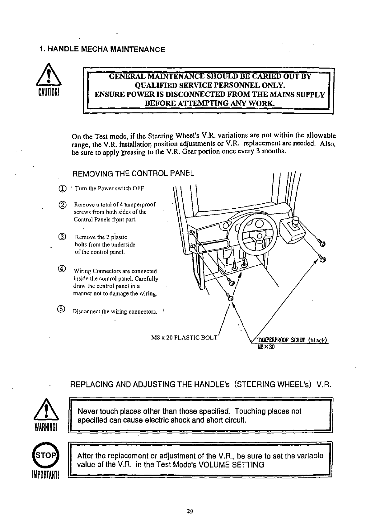
1. HANDLE MECHA MAINTENANCE
Lt
CAUliONI
CD
® Remove a total
® Remove the 2 plastic
GENERAL
ENSURE
On the Test mode, if the Steering Wheel's V.R. variations are not within the allowable
range, the V.R. installation position adjustments or V.R. replacement are needed. Also,
besure to apply greasing to the V.R. Gear portion once every 3 months.
REMOVING
.
Tum
the Power switch OFF.
screws from both sides
Control Panels front part.
bolts from the underside
ofthe
control panel.
POWERISDISCONNEcrED
THE
of
4 tamperproof
MAINTENANCE
QUALIFIED
BEFORE
CONTROL
of
the
SHOULD
SERVICE
ATTEMPTING
PANEL
BE
cARIED
PERSONNEL
FROM
ANY
THE
WORK.
ONLY.
MAINS
OUT
BY
SUPPLY
CD
®
~
WARHIHGI
Wiring Connectors are connected
inside the control panel. Carefully
draw the control panel in a
manner not to damage the wiring.
D;_"~""
REPLACING
Never
specified can
e wiring connectors. ' /
AND
ADJUSTING
touch
places
cause
other
electric
x 20 PLASTIC
M8
than
shock
THE
those
BOLT
HANDLE's
specified. Touching
andshort
(STEERING
circuit.
TAllPERPROOF
I18X30
places
SCREI
WHEEL's)
not
(black)
V.A.
€T3
Afterthe
valueof
IMPORTANTI
replacementoradjustment
the
V.A.
intheTest
Mode's
of the
VOLUME
29
V.A.,
besure to set
SETIING
the
variable

ADJUSTING THE V.R.
CD
By using the Spanner,loosen the 2 Hexagon bolts which secure the V.R. Bracket, move
the V.R. Bracket and disengage the gear mesh.
@ Ensure that the V.R. value is within the range
of
the centering position.
® Mesh the gears to secure the V.R. Bracket. At this time, ensure that an appropriate
backlash is obtained.
@ When the Steering Wheel is in the centering position, if the V.R. value is not
appropriate, make fine adjustments by loosening the 2 screws which secure the V.R.
gear, turning the gear holder and making sure that the V.R. value is appropriate.
®
Tum
the Steering Wheel to check V.R. value variations.
GREASING
Apply greasing to gear portions once every 3 months.
Use Part No. 090·0044 GREASE
NET
300g (Shell
AU~O
Grease).
Apply Grease
30

The
Steering Wheel's right-hand side V.R. is for the
the
left-hand
mode
screen.
Normally,
screen.
The
following
1
Remove
Disconnect the connectors (3P yellow, 3P red)
Connect
~3
®
®
Drive
The
the V.R.
After
and
Steering
making V.R. adjustments, connect connectors.
side
V.R. is for the Motor
the
V.R. value for the
To
check
the
the
the
value
the V.R. value for the
shows
Control Panel.
Wiring
Connector connected to the V.R. for the
Wheel
for the
each V.R. value.
Connector (3P yellow) which
value on
Motor
Game
the
INPUT
Drive BD.
Game
Drive
BD. Check the V.R. value on the
BD & Drive Control is
Motor
TEST
Drive
of
both Variable Resistors.
comes
mode
Board &
BD, follow the procedure below.
from the V.R.
Game
screen in the
shown
BD &
Drive
Drive
Test
Control, and
on the
for
the
Control.
mode
Test
Test
Motor
will be
mode
Game
For
BD&Drive
V.R.
for
Motor
Control:
Drive
REPLACING THE V.A. I
After
disconnecting the V.R. to be replaced, take
Bracket by using the Spanner, and then
replacement,
V.R.
for
Motor
DriveBO(3P
220-5373or220-5484
SCRE'II
(2)
114
X12, willat
spring washers
and
BD:
check
ellow
Left
30H or
30H or lower
V.R. value variations in the
Connector)
lower
Centering
..-
..-
remove
V.R.
220-5373or220-5484
position
7DH-83H
7DH-83H
off
the 2 screws which secure the V.R.
the V.R. with the gear as is attached. After
Test
mode.
for
Game
BD&Drive
--+
--+
Control
Right
or
(3P
higher
red
Connector)
(2)
wi!
Iat
COH
COHorhigher
SCRE'II
114x12,
spring vashers
and
VR
BRACKET
, .
VRBRACKET
31

2. ACCELERATOR & BRAKE UNIT
GENERAL MAINTEN CE SHOULD BE CARIED OUT BY
&
WARNING
I
ENSURE POWER IS DISCONNECTED FROM
QUALIFIED SERVICE PERSONNEL ONLY.
BEFORE ATTEMPTING ANY WORK.
Inthe
test
mode,ifthe
V.R.
value
isnot
an
adjustmentofV.R.
ora
replacementofV.R.isneeded.
grease
the
ACCEL-&
sliding
porions
To
perform
screws
backofthe
and
the
remove
cockpit.
ACCEL&BRAKE
within
the
installation
BRAKE
once
every3months.
above
operation,
BACK
allowable
LIDBfrom
~AINTENANCE
range,
position
Also
shafts
and
take
off
the
4
the
THE
MAINS SUPPLY
ADJUSTING AND REPLACING THE V.R.
Never touch
~
specified can cause electric shock and short circuil.
WARNINGI
The ACCEL. & BRAKE
V.R. is on the left-hand side and the
Check the V.R..valueinthetest
Method of V.R. replacement
To replace the
taking
from the
replaced, take out the 2
screws which secure the
off
V.R.,
the connector
V.R.to be
V.R.Bracket, and remove
the
V.R.together with the
bracket and gear. After
the replacement, check
V.R.value variations
the
in the test mode.
places other than those specified. Touching places not
MECHA
ACCBL. :
BRAKE:
after
can beseenby removing the BACK LID B. The
BRAKE
mode.
When released:
Under 30 H
V.
R.
220-5373
V.R. is on the right-hand side of the
Theappropriatevalueof each V.R. is as
Under 30 H
,
When stepped on:
follows:
OverCOH
OverCOH
ACCEL.
MECHA.
SCREI
(2)
IU
X8.
USing
spring
washer
32

Method of V.R. adjustment I
CD
Loosen the 2 screws which secure the V.R. Bracket and move the V.R. Bracket to
disengage the gears.
@
Have
the V.R. value match with the value obtained when the pedal is released.
® Mesh the gears to secure the V.R. Bracket. At this time, be sure to obtain an
appropriate backlash.
@ Step on the pedal and check V.R. value variations. If the value is not within the above
appropriate range, loosen the 2 screws which secure the ADJUST GEAR to make an
adjustment.
GREASING
Apply greasingjothe gear and shaft portions once every 3 months.
PART
Use
Apply greasing in the following procedure:
CD
Take
(black) to pull out the unit. At this
time, be very careful so as not to'
damage the wiring.
No. 090-0044 GREASE NET 300g (SHELL AUTO).
off
the 4 Hexagon Bolts
® Disconnect the wiring connector
and move the unit,
which is 6kg." to a spacious place
in which the
performed.
work can easily be
® Remove the 4 Tamperproof
Screws (black) which secure the
Pedal Cover and remdve the Pedal
Cover
@
Remove
At this time, ensure that the ACCEL pedal and
are subjected to torsion spring force. .
by moving it forward.
the Pedal Shaft from the lower portionsofACCEL. pedal and BRAKE pedal.
® After applying.greasing to each part, assemble in the procedure opposite as when
disassembling.
th~
weight
of
AGeEL.
PEDAL
BRAKE
HEXAGON
M8x
pedal are firmly secured as they
:
16,
BOLT
'/flal l
black (4)
spring
rashers
GREASING
PEDAL
SHAFT
using
1112
spr ing washer
/
cf"/
TAMPERPROOF
(4) 1l4X8
SCREW
(black)
33 -
~
GREASING
Accel.
Gear
s.de &
part
GREASING
~p"'ed"'a'fl
Brake
"'S""ha-;f-t
-rem-oY-e-;d
side
,
-a-s
-p-e
r'"""®"ab-o~Ye:-.

3. SHIFTLEVER
MAINTENANCE
~
WARNINGI
CD
<ID
® Disconnect the Connectorto removethe Shift Lever Unit.
@)
When reinstalling, followthe procedureopposite as whenremoving. At this lime,
ensure that
In the Test mode,ifthe
SWitch.
the
When performingtheabove work, remove the Shift Lever Unit.
ENSURE POWERIS DISCONNECTED
REMOVING
Tum thePowerSW off.
Remove the4 TamperproofScrewsto lift the Shift LeverUnit.
Applygreasing.to the Mechanism'sslidingportiononce every 3 months.
GENERAL MAINTENANCE SHOULD BE
THE
"DOWN"
SHIFf
QUALIFIED SERVICE PERSONNEL ONLY.
BEFORE ATTEMPTING ANY WORK.
SHIFT
displayappearson the upper partasshown.
LEVER'sSW can notbe inputted satisfactorily,replace
CARIEDOUT
FROM
LEVER
THE
TAllPERPROOF
jp
,/
./
BY
MAINS SUPPLY
SCREI
(black) (4)
SWITCH
Method of
CD
Disconnect the wiringConnectorof
the Switch to be replaced. .
<ID
Remove the 2 TappingScrews
(M3X16)
GREASING
Apply greasingonce in 3 months 10
the specified portions.
Por spray grease,useNOK KLUBER
L 60 or Grease Mate(PartNo. 090-
0066).
REPLACEMENT
replacement
to replace theMicroswitch.
TAPPlt«>
lOx
SCREI
16
GREASlt«>
2
I
IIICROSlflTOl
34

5..FUSES
FUSES SHOULD ONLY BE REPLACED BY QUALIFIED
SERVICE PERSONNEL.
DISCONNECT THE MACHINE FROM THE WALL BEFORE
ATTEMPTING ANY WORK.
There are a numberoffuses used in this machine to protect the user and the machine itself from
electrical overload. The following is a listoffuses used and their locatins within the machine:
PART NUMBER
838-11966
838·11855
838-11650
400-5306-01
514-5078-10000
514-5078-5000
LOCATION
Motor Drive Board
Ref: FI
Conn Bd
Ref: FI
Eq.AmpBd.
Ref: FI
SMPS
Ref: FI
Eurosocket
AC Bracket
Nanao Monitor
Ref: I
Sanwa Monitor
Ref: F801
TYPE DETAILS
7A32mm
240V Glass
5A20mm
240V Glass
6A20mm
240V Glass
4A20mm
240V Glass
lOA 20mm T
240V Ceramic
5A20mm
240V Ceramic
6.3A20mm
1251240VGlass
4A20mm
1251240VGlass
T
T
T
T
T
F
F
QTY.
2
2
2
2
2
2
2
Sanwa Monitor
Ref: F801
36
I.5A20mm
1251240VGlass
F
2
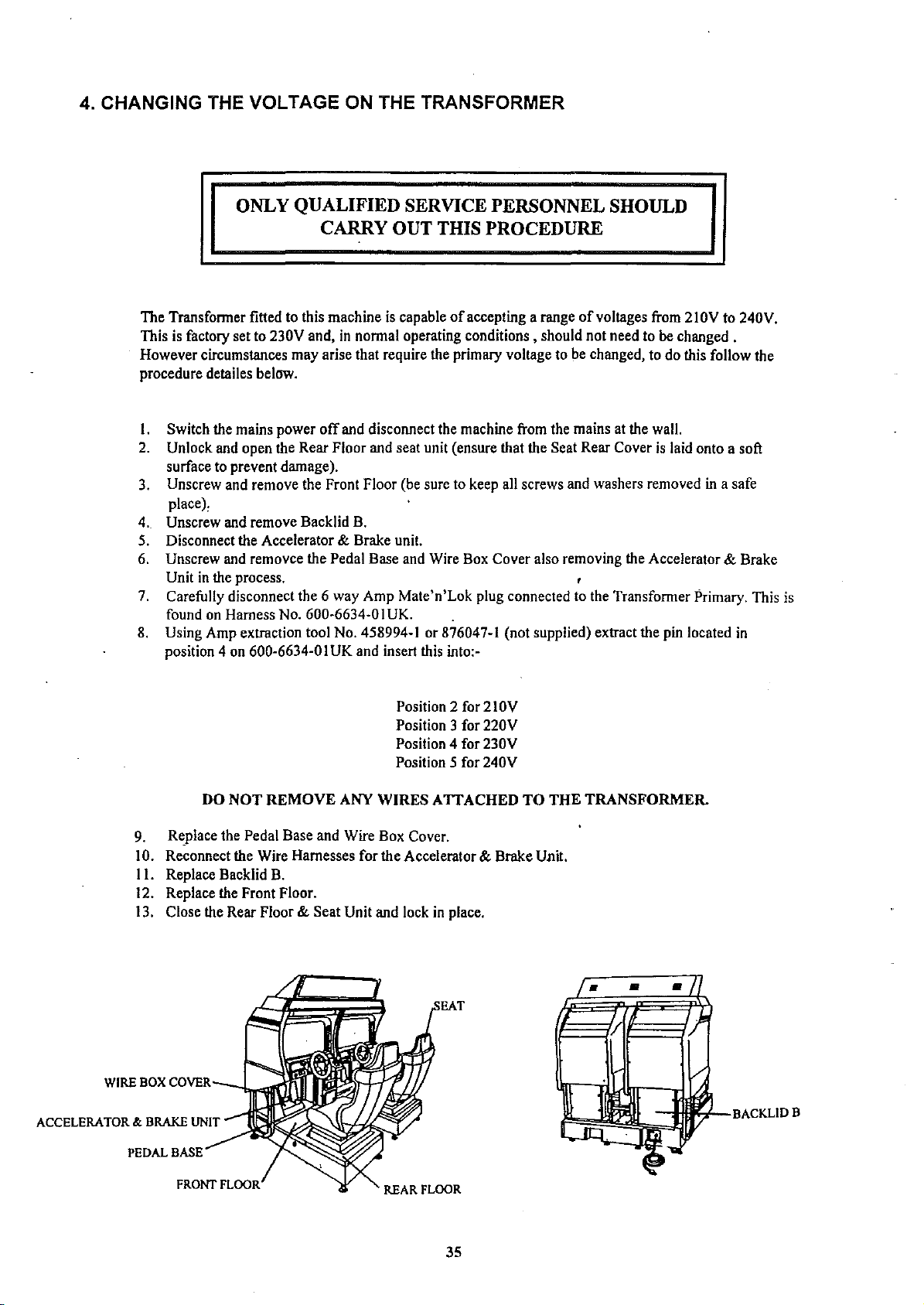
4. CHANGING THE VOLTAGE ON THE TRANSFORMER
ONLY QUALIFIED SERVICE PERSONNEL SHOULD
CARRY OUT THIS PROCEDURE
The Transformer fitted to this machine is capableofaccepting a rangeofvoltages from 210V to 240V.
This is factory set to 230V and, in normal operating conditions, should not need to be changed .
However circumstances may arise that require the primary voltage to be changed, to do this follow the
procedure detailes below.
off
I. Switch the mains power
2. Unlock and open the Rear Floor and seat unit (ensure that the Seat Rear Cover is laid onto a soft
surface to prevent damage).
3. Unscrew and remove the Front Floor (be sure to keep all screws and washers removed in a safe
place),
4.. Unscrew and remove Backlid B.
5. Disconnect the Accelerator
6. Unscrew and removce the Pedal Base and Wire Box Cover also removing the Accelerator
Unit in the process.
7. Carefully disconnect the 6 way Amp Matc'n'Lok plug connected to the Transformer Primary. This is
found on Harness No. 600-6634-0IUK.
8. Using Amp extraction tool No. 458994-1 or 876047-1 (not supplied) extract the pin located in
position 4 on 600-6634-0 IUK and insert this into.-
and disconnect the machine from the mains at the wall.
& Brake unit.
& Brake
9. Replace the Pedal Base and Wire Box Cover.
10. Reconnect the Wire Harnesses for the Accelerator
II.
Replace Backlid B.
12. Replace the Front Floor.
13. Close the Rear Floor
WIREBOX
ACCELERATOR&.BRAKE
PEDAL
COVER
BASE
NOT
DO
~--I..""';
UNIT
Position 2 for 210V
Position 3 for 220V
Position 4 for 230V
Position 5 for 240V
REMOVE
ANY
WIRES
& Seat Unit and lock in place.
ATIACHED
& Brake Unit.
TO
THE
TRANSFORMER-
•
•
•
BACKLIDB
REAR
FLOOR
35

7. PERIODIC INSPECTION TABLE
~
WARNINGI
The items
listed
belowrequireperiodic check andmaintenance to retainthe performance
of thismachineandensuresafe operation.
BE SURE TO CHECKANNUALLY TO SEE IF
PLUG IS SECURELY INSERTED, THERE IS NO DUST BETWEEN THE SOCKET OUTLET
AND
THE
POWER PLUG ETC. USING
CAUSE A FffiE OF ELECTRIC SHOCK.
PERIODICALLY REQUEST
DISTRIBUTOR, ETC. WHERE
THE
INTERIOR CLEANING. USING
CAUSE A FIRE OR ACCIDENT. NOTE THAT CLEANING
THE
THE
PERFORMED ON A PAY-BASIS.
THE
PLACE OF CONTACT HEREIN STATED OR
PRODUCT WAS PURCHASED FROM, AS REGARDS
THE
THE
POWER CORDS ARE DAMAGED,
PRODUCT IN A UNCLEAN CONDITION MAY
PRODUCT IN AN UNCLEAN CONDITION CAN
THE
INTERIOR PARTS CAN BE
REGULAR INSPECTION SHOULD BE CARIED OUT BY QUALIFIED
SERVICE PERSONNEL ONLY.
THE
THE
Item Interval
HANDLE MECHA
ACCEL
SHTFTLEVER
COIN CHUTE TOWER
MONITOR
SEAT
GAMEBD
INTERIOR CLEANING
POWER SUPPLY PLUG
REAR CABINET APPLY GRESE TO SEAT RAIL
CABINET SURFACES CLEANING
CONTROL PANEL
& BRAKE
,CHECK V.R. VALUE
CHECK ADJUST GEAR ENGAGEMENT
GREASING OF GEAR
CHECKV.R. VALUE
CHECK ADJUST GEAR ENGAGEMENT
GREASING OF GEAR AND BEARING
CHECKSW
GREASING
CHECK COIN SW (IF
CHECK ADJUSTMENTS
ANTISTATIC MEASURES
MEMORY TEST
CHECK
INSPECTION AND CLEANING
LAMPS OPERATING
SEnlNGS
FinED)
MONTHLY
TRIMONTHLY
TRIMONTHLY
MONTHLY
TRIMONTHLY
TRIMONTHLY
MONTHLY
TRIMONTHLY
MONTHLY (IF
MONTHLY
BIMONTHLY
MONTHLY
MONTHLY
ANNUALLY
ANNUALLY
TRIMONTHLY
AS REQUIRED
MONTHLY
FinED)
38

6. REPLACING THE FLOURESCENT LAMP AND LAMPS
~
CAUTIONl
TRUSS
M4x8
ENSURE
Openthe
scm (3
GENERAL MAINTENANCE SHOULD BE CARIED OUT BY
QUALIFIED SERVICE PERSONNEL ONLY.
POWER
Billboardasshowntoreplace
IS DISCONNECTED
BEFORE ATTEMPTING ANY WORK.
theFluorescent
FROM
Lamp
THE
and
Lamps.
WlP
(Removetoreplace
MAINS SUPPLY
LID
lamps)
fI1JORESC£Hl'
GUlf
LAIIP
UIIP
390-5638-4
401
P
UIIP11OV
390-5167
301
37

PROBLEMS
CAUSE
COUNTERMEASURES
Operationof Accel,
and Brake Pedalsarc
not satisfactory.
SHiFf
LEVER
doesn'toperate
satisfactorily.
SteeringWheel
reactionstrengthis
incorrect.
Deviation of Center.
Steering Wheel
reaction strength
is insufficient
No SteeringWheel
Reaction.
V,R.
position
deviated,
V.R.malfunctioning.
ADJUSTGEAR',
Swiech
malfunctioning.
Power
ONcheck
V.R.
position
malfunctioning,
V.R.
Reaction
Meeha's
Connector
The
Motor Drive BD fuse is blown
momemary
engagement
nOI
deviated.
secular
Connection
overload.
performed
isnotcorrect,
change.
isincorrect.
correctly,
due
to
Adjust V.R. value in the rest mode.
Replace
Adjust
Replace
theV.R.
theengagement of ADJUSTGEAR.
theSwitch
Tum offpowerandthenturn it backonagain.
Complete
Adjust V. R. value in the test mode.
Replace
Change
Check:
Replace the Motor Drive BD Fuse
the
power
oncheck.
V.R.
Drive
Control
BDDIP SWselling
connector connection
from
Baseto
Handle.
Fluorescent lamp Fluorescentlampneeds
,
doesn'tlight up.
The connector isdisconnected. Checkconnector connections inthe
The LEADERlamp The lamp is burntout.
does not lightup.
The connector is disconnected.
Interactiveplayis not
Communication cableisdisconnected.
possible.
Cable
connections
Settingsfor
Ire
communication
correct.
replacement.
notcorrect.
play
Ire
not
Replace
Replace
theIlucrescent lamp
thelamp
billboard
case
Checkconnector connections in the billboard case
Connect
Connect
Ensure
COJTCCI
the
cable.
thecablecorrectly
thaI
GAME
ASSIGNMENTS
settings
are
40

REAR CABINET (Greasing to Seat Rail Portion)
Move the Seat to the reannost
portion and apply spray greasing to
the portion shown at the right once
every 3 months by using NOK
KLUBERL60or GREASE MATE
SEGA PART No. 090-0066.
After greasing. move the Seat a
few times forward and backward
so as to allow the grease to
be
applied all over uniformly, Be
sure to wipe grease which attaches
to the surfaces of the PROTECT
RUBBER on the Seat Rail. or any
excess grease.
CLEANING THE CABINET SURFACES
When the cabinet surfaces are badly soiled, remove stains with a soft cloth dipped in water or
diluted (with water) chemical detergent and squeezed dry. To avoid damaging surface finish. do
not use such solvents as thinner. benzine, etc. other than ethyl alcohol, or abrasives, bleaching
agent and chemical
du~tcloth.
8. TROUBLESHOOTING
In
caseaproblem
PROBLEMS
When
the
main
SWis
turnedON,the
machine
is not
activated.
Thecolorof imageon
MONITOR
incorrect.
The
of
the
andor shrinks.
Sound
screen is
on-screen
monitor
is notemitted.
image
sways
CAUSE
The powerisnotON.
Incorrect
ACUNlT
duetoinstantaneous
Incorrect
The
power
Sound
occurs, first
power
FUSE
monitor
source
volume
I
source/voltage.
functioned
overcurrent.
adjustment.
and
adjustmentisnot
check
voltage
IfC
correct.
not
wiring
correct.
connector
connections.
COUNTERMEASURES
insert
Firmly
Make
First,
thefuseto its
Make
Makesurethaithepower
correct.
Adjustlhe
volume
Iheplugintothe
sure
lbat
remove
the
original
appropriate
SWITCH
(comrol)
the
power
cause
of
status.
adjustments
UNIT's
supply/voltage
over
supply
outlet.
current
and
andvoltsgeare
sound
adjustment
are
replace
correct.
t
MalfunctioningBD.•ndAmp.
Connector
connectionisincorrect.
39
Perform
Check
SoundTest10 checkil.
connector
connection
from
Basc(0Speaker.

9. GAME BOARD & DRIVE CONTROL BOARD
..
In order to prevent an electric shock, be sure to turn power off before
Lt
WARNING
I
Lt
CAUTION
I
CD
REMOVING THE BOARD
To replace the IC BD (such as Game BD, Drive BD, etc.), or to change DIPSW settings, take out
the IC BD by using the following procedure:
Tum
performing work by touching the interior parts of the product.
..
Be careful so as not to damage wirings. Damaged wiring can cause
an electric shock or short circuit accident.
Do not expose the Game BD, etc. without a good reason. In this product,
setting changes are made during the test mode. The Game BD need not
be operated. Use the Game BD, etc. as is with the same setting made at
the time of shipment.
the MAIN SW off.
® Unlockand take off the2 Mushroom Headscrews
®
Tum
the knob to unlock. The seat can be inclined in the direction shown. When inclining the
seat, be careful so
seat to come into contact with the floor.
If
the floor has hard surfaces, protect the seat from damage by using a cloth, etc. on the floor
surfaces.
<D
Take
off
the 3 screws tb remove the case lid.
(§)
Take
off
a total of 4 screws from both sides with the seat being in an inclined state andremove
BASE
LID F. Removing Base Lid
asnot to damage the seat parts. Carefully cause the backrest portion of the
Fallows
from
The
ELEC
the sideofthe baseas shown.
Game
Board is contained in the Shield Case.
BASE
to be viewed.
UIILDCK
MUSHROOM HEAD
Ms
X16
SCRE'll
CHROME
.-
(2)
BASE
LID
TRUSS
115XI2,
SCRE'll
114
F
HEAD
SCRE'll
(4)
black
(3)
XS,
wlllat~spring
CASE
.ashers
LID
41

DRIVE
CONTROL
BD
MOTOR
DR!VEBD
SOO~
BD
® The Drive Control BD is contained in the Shield Case. The Steering Wheel reaction is
l's.
set using the Drive Control BD DIP SW
Lid to perform DIP W setting. Use
the strength as given in the table below. Ensure that all other DIP
cg
0
0
j
!
c=:::J
Drive Control
Remove the 5 screws and open the Shield Case
Bd's
DIP SW No.1 's switches I to 3 to set
SW's
are OFF.
o~
DIPSW
NOTE: The shaded portion refers to the
selling at the time of shipment.
SETTING
SCREW
114XB
spring
ELEC
••
/flat
washers
BASE
(5)
&
co
~
0
I
81a
o a
DRIVE
~
~
0
a/c:::JDlPSW2
CONTROL
0
c:::JDIPSWl
a
BD (838-11967)
DIP SwITCH
ON
.J .J .J X X X
m;;l
BBBBBDBD
1
234
~
0
0
1
0
~
567
1 2
OFF
ON OFF OFF
OFF ON
OFF
ON
ON
OFF
: OFF
OFF ON
ON ON
OFF
OFF
ON
No, 1
X X
8
3
FUNCTION
Light
Heavy
42

I REPLACMENT AND ADJUSTMENT OF FUSE
• In order to prevent an electric shock, be sure to turn power off before
Lt
WARNINGI
performing work by touching the interior parts of the product.
• Be careful so as not to damage wirings. Damaged wiring can cause
an electric shock or short circuit accident.
• Be sure to use fuses meeting specified rating. Using fuses exceeding
the specified rating can cause a fire or electric shock.
•
The
fuse is provided on
the Motor Drive BD.
When replacing,
to use the specified fuse.
be sure
F1JSE
7A
514-5036-7000
fg
~~OO
rnm&
co»CJ
0 0
I
MOTOR DRIVE BD (838-11966)
c::::J
Clf9l
0
I
=0
,
,
=.,
'5l
43

COMPOSITION OF GAME BOARD
GAME BD STCC TWIN
~~~
~
~-~~--~---~--
COMllBDSTCC
837-12781
ROMBDSTCC
lWIN
834-12780
lrnEL2C-CRX
IlAINBDCOM
837-12469
•
0
ROM BD STCC TWIN
0
IC35
le1.
MPR-1CJ261
lell
le32
MPR-19259
le)1
EPR-1,214
...
~~t
..
...
~
'
0
~
N
...
'"
~
..
..
a a tx a
~
N
M
"
'"
•
U
~
0
r-
..
N N
~
..
~
;:.
W
~
N
~
N
~
..
a
Q.
W
0
N
'"
~
..
Q.
•
..
u
SEGA
~
..
~
"
..
~
W
0
Q
;;;
N
~
~
,
a
~
~
•
u
0
M
N
'"
..
..
a a a
••
..
~
..
N
NWN•N
'"
•
u
I
~
u
~
Q
e-,
~
N N N N
~
~
..
..
a a
Q
Q.
~
wuw
..
N N
'"
..
Q.
~
u u
r-
'"
~ ~
..
a a
~
~ ~
"
U
•
•
'"
~ ~
.. ..
~
OD
OD
'"
..
N
U
•
~
..
N
a
~
W
44

9. COMMUNICATION PLAY
For
this
game,
4 machines can be connected to
allow
up[08 players[0play
simuhaneously.
INSTALLA
I)
When Linking a numberofmachines, be sure
to supply sufficient power for the corresponding
numberofmachines. The per unit standard
voltage/amperage is 210-240V /4.6-4A.
Duetothe
2)
the
distance
approximately
CONNECTING
TION
lengthofthe communications cable.
PRECAUTIONS
in between the machines will be
0:2 meters or less.
THE
COMMUNICATION
•
CABLES
•
• II
•
•
I!
II
I!
II
II
APPOOX
IllATaY
O.2Ja
Take
off
the
4 screws and remove AC
The HOLE LID is attached over the AC COVER HOLE. By laking
HOLE LIDofthe side where the other machine is to beinstalled.
AC
COVER
COVER
B
B . "
TRUSS'
washers
IDLE
off2
screws. remove the
HEAD
SCREW
\.
at spring
LID
.'
(2EA)
-_.
-
45

PAGE
INTENTIONALLY
BLANK
LEFT

Connect the communication cable. Redo the connection which is currently made for TWIN (for
2P LINK) to change it for usage by 4P or more.
Depending on the number
Make connection correctly as shown below.
The Fibre Optic cable is used for the communication linkage.
€~
IMPORTANT!
Excessive bending may damage the communication cable. Be very
careful in this regard.
BLACK
RFD
(TX)
(RX)
of
units to be connected. communication connections are different.
=---~
1m
l8XJ
0
0
D
0
•
Ql
•
0
0
"""'"'""
0
0
.:
~
..
CABINET
CAR 1
-
~
2P
to'
n
LINK
n
..
.
CABINET
CAR
2
•
0
n
":
0
Ql
r-
p
..
n
Ql
:"--
••
p
n
+
ACUNIT
n
-
.
.
.-
n
..
CABINET
CAR
1
..
-
..
CABINET
CAR
2
n
-
•
4P
LINK
..
CABINET
CAR
3
p
..
..
CABINET
CAR
4
p
n
..
CABINET
-CAR
1
..
CABINET
CAR
2
•
..
CABINET
CAR
3
6P
.
LINK
CABINET
CAR
47
..
C
n
..
CABINET
CAR
5
n
_n
..
CABINET
CAR
6
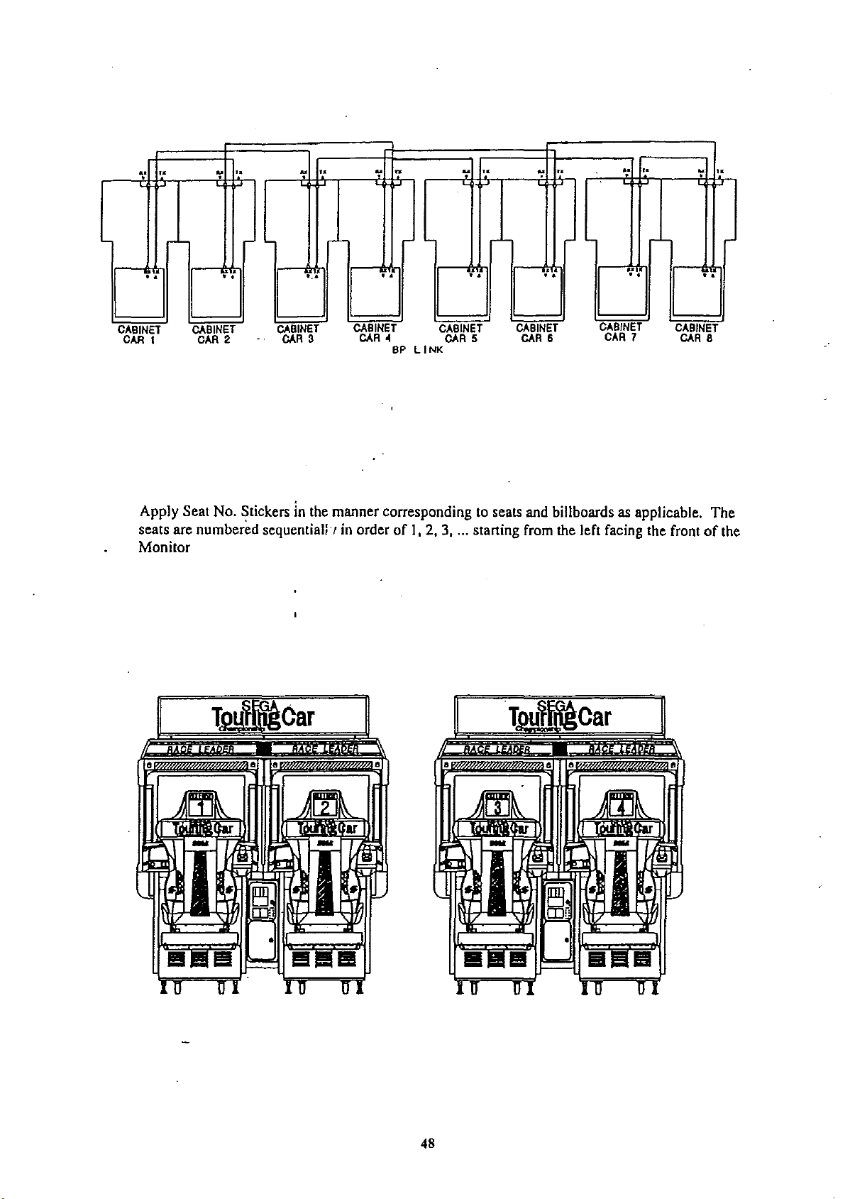
-L
..
>-'
,.
,.
':
..
':
':
...
..
;r
-..:
~
..
>-'
..
':
r'
...
,.
':
..
..
r'
..
CABINET
CAR 1
Apply Seat No. Stickers in the manner corresponding to seats and billboards as applicable. The
seats are numbered sequentiallr in order of I, 2, 3, ... starting from the left facing the front
Monitor
..
CABINET
CAR
2
•
'.'
CABINET
CAR
3
..
CABINET CABINET
CAR
~
BP
LINK
CAR
..
5
.
..
CABINET
CAR
6
~
..
CABINET
CAR
7
CABINET
CAR
..
8
of
the
48

SETIING
e
IMPORTANTI
FOR
COMMUNICATION
PLAY
During interactive play,ifcommunication is interrupted due to some cause,
the game will be interrupted, with the Network Check screen appearing.
When performing communication play, the settings of
GAME
ASSIGNMENTS in the test
mode need to be changed.
<D
Cause all of the machines linked for communication play to enter the test mode.
® Set the LINK TYPE of the machines connected for communication play to CAR I, CAR 2, CAR
3 ....sequentially in order starting from the left facing the screen. At this time make sure that there
is no duplicated number.
One machine whose LINK TYPE is set to CAR I will be the MASTER unit. Thereafter, all other
machines' settings except for ADVERTISE SOUND,
compulsorily be the same as those
of
the MASTER unit.
CABINET
TYPE
and
LINK
TYPE
will
® After changing the settings of all machines connected for communication play, ensure that all of
the machine exit from the test mode.
<D
In the NETWORK CHECK, if there is no irregularity, the ADVERTISE mode will appear, allowing for communication play.
ADVEATISE
URL
COUNTRy
CABINET
LINK
DIFFICULTY
GAME
DEfAULT
NAME
>
EXIT
GAME
ASSIGNMENTS
ADDRESS
TYPE
TYPE
MODE
CAR
ENTRY
SOUND
.
xxxxx
xxxxx
xxxxx
xxxxx
xxxxx
xxxxx
xxxxx
xxxxx
xxxxx
----I-
This
sets
CAR
l-CAR
8
SELECT
AND
• GAME
CAUTIONS
WITH
PUSH
ASSIGNMENTS
SeRVICE
TEsT
TO BE
BUTTON
BUTTON
HEEDED
WHEN
USING
THETEST
MODE
Exiting from the test mode causes the unit to perform the network check automatically. During
this time, all
Therefore, be sure not to enter the test mode if
of
the linked units will not allow the game to be played in normal status.
anyoneofthe units is in play. On the other
hand, if even one unit is in the test mode, make sure that other machines are not in play.
49

10. PARTS LIST
1.
TOP
ASSEMBLY STC-0002/3UK
are
There
Although they
are
also a few assemblies which
STC-00002UK
Seq. No.
currently two different monitors fitted to SEGA Touring Car.
are
Part
Number
STC-INST-KIT ASSY INSTALLATION KIT STCC UK
1
2
STC-6000UK
3 STC-11001UK ASSY COCKPIT STCC UK
4 STC-7000UK IASSY MONITOR HANDING
INY-0004 BACK LID INY
5
6 DYN-0008XUK BACK LID B UK
421-7987
7
8 421-7020UK STICKER CAUTION FORK
421-7988-91
9
10 PK0034
11 PK0086 CARTON MAIN STCC
12 RAL-XXXX-13UK
13 PK0037
16
iLB1092 STICKER CE 25mm X 25mm
17 IOS1080 TAPE ALL WEATHER
18 1440-CS0011XEG
19 421-8543UK
20 421-8544UK
201
202 008-
203 000-P00408-WB
204 FX0410
205 LB1046
206 LB1003
207 LB1004
208 LB1020 LABEL CAUTION (YEUBLK)
210 440-WSOO02XEG
008-B00820-0C
T00412-0C
identical there
Descrlp[tion
ASSY HANDING KIT STC TWIN
STICKER ELEC SPEC
STICKER SERIAL NUMBER
PALLET WOODEN RALLY
LOCK COVER UK
BAG PLASTIC RALLY
STICKER C GRIP HANDLE 2
STICKER CABINET L UK
STICKER CABINET R UK
M8X20 MSCR TMP PRF BH CRM 4
M4X12 MSCR TMP PRF CRM
M4X8 MSCR POSI PAN W/FS BNP
M4X12 TAPTITE POSI PAN PAS
LABEL TESTED FOR ELEC. SAFETY
LABEL "FAILURE TO..DAMAGE"
LABEL "CONNECTIONS....."
STICKER W POWER OFF
are
two different
are
affected by this.
part
numbers, therefore there
Qty.
1
1
-~
1
2
2
1
4
3
2
i
2
2
2
1_
0.01
!
:
1
1
8
26
4
1
1
1
1
6
50

STC-00003UK
Seq. No.
1 STC-INST-KIT ASSY INSTALLATION KIT STCC UK
2
3
4 STC-7000UK ASSY MONITOR HANDING
5 INY-0004
6 DYN-0008XUK BACK LID B UK
7 421-7987
8
9 421-7988-91
10 PK0034
11
12 RAL-XXXX-13UK
13 PK0037
ILB1092 ISTICKER CE 25mm X 25mm
16
17 OS1080
18 440-CS0011XEG STICKER C GRIP HANDLE
19 421-8543UK STICKER CABINET L UK
20 421-8544UK STICKER CABINET R UK
21 EP1317 FERRITE CORE ROUND CABLE CLAMP
201
202 !008-T00412-0C
203 1000-P00408-WB IM4X8 MSCR POSI PAN W/FS BNP
-
204 M4X12 TAPTITE POSI PAN PAS
205 ILB1046
206
207 LB1004
208
210 1440-WS0002XEG ISTICKER W POWER OFF
!008-B00820-0C IM8X20 MSCR TMP PRF BH CRM
IFX0410
LB
I
!LB1020
Part
Number
STC-6000UK ASSY HANDING KIT STC TWIN
STC-11002UK
421-7020UK STICKER CAUTION FORK
PK0086 CARTON MAIN STCC
1003
I
Description
I
ASSY COCKPIT STCC SANWA UK
BACK LID INY
STICKER ELEC SPEC
STICKER SERIAL NUMBER
PALLET WOODEN RALLY
LOCK COVER UK
BAG PLASTIC RALLY
iTAPEALL
IM4X12 MSCR TMP PRF CRM
LABEL TESTED FOR ELEC. SAFETY
LABEL "FAILURE TO..DAMAGE"
WEATHER
ILABEL "CONNECTIONS....."
LABEL CAUTION (YEUBLK)
!
I
i
;
i
,
,
I
I
QIy.
1
1
2
1
2
2
1
4
3
2
2
2
2
1
0.01
2
1
1
1
4
8
26'-
._
4
._.-
1
1
1
.~
..-
51

•
52

2. BILLBOARD ASSEMBLY STC-0200UK
Seq.No.
1
2
3
4
5
6
101
201
202
301
PartNumber Description
STC-Q220UK
STC-Q210UK
RAL-Q201UK
RAL-Q202UK
440-WS0012XEG
44o-WSOOO2XEG
LB1096
000-
T00408..QC
FX0011
LM9511
ASSY
BILLBOARD
ASSY
BILLBOARD
LAMP
LID
STAYBRKT
STICKER
STICKERWPOWER
STICKER
M4X8
MSCRPOSITH CRM 3
M4NUTFLGSERBZP
LOOM
EARTH
LOWER
UPPER
W HIGHTEMP
OFF
PROTECTIVE
EARTH
750mm 1
Qty.
1
1
2
2
1
1
1
5
53

3. BILLBOARD UPPER ASSEMBLY STC-0210UK
Seq.No.
1
2
3
4
5
6
7
101
201
202
203
301
PartNumber Description
RAL-0211UK
RAL.o212UK
RAL.o213UK
RAL.o214UK
RAL.o215UK
423.0274
STC.o240UK
LB1096
000-
T0040B-OC
FX0163
FX0011
LM9111
BILLBOARD
CORNER
CORNER
CORNER
CORNER
BILLBOARD
ASSYFLTWIN
STICKER
M4XB
MSCR
NBX112"
M4NUT
LOOM
SrrAP
FLG
EARTH
CASE
EDGE
EDGE
EDGE
EDGE
PLATE
PROTECTIVE
UPPER
UPPER
LOWER
LEFT
RIGHT
UPPER
POSITHCRM
POSI
FLG
SERBZP
300mm
STCC
EARTH
BZP
aty.
1
1
1
1
1
1
1
1
12
2
1
1
54

4. BILLBOARD
LOWER
ASEMBLY STC-0220UK
Seq. No.
1
2
3
4
101
201
202
203
204
Part Number
RAL-0221UK
RAL-0222UK
423-0275
STC-0230UK
280-A00500-A
000-T00408-0C
FX0037
FXOO09
FX0243
Description
BILLBOARD
CORNER
BILLBOARD
ASSY
ROUTER
M4X8
MSCRPOSITH CRM
M4X12
M4
WSHR
M4
WSHR
o
CASE
EDGE
PLATE
LAMP
UNIT
lWIST
MSCRPOSI
FORM
SPRBZP
LOWER
LOWER
05 ADH
PAN
BZP
A FLT BZP
Qty.
1
1
1
2
4
6
4
4
4
o
55

5.
LAMP
UNIT
Seq. No.
1
2
101 214-0110 BULB SOCKET
102 390-5167 LAMP
103 280-A00500-A ROUTER TWIST
201 FX0031 M3X16 MSCR POSI PAN BZP
202 PP1107 GROMMET RUBBER 1.61dia50 MATL
301 600-6555-07UK LOOM LAMP UNIT
ASSEMBLYSTC-0230UK
Part
Number
RAL-0231UK LAMP PANEL
421-7501-16UK STICKER 11OV30W
Description
110V30W
05
ADH
Qty.
1
3
3
3
7
6
2
1
o
.0
o
o
o
o
56

6.
FLUORESCENT
ASSEMBLY STC-0240UK
Seq.No.
1
2
3
4
201
202
301
PartNumber Description
STC-0241UK
390·5538-40-AUKFLLIGHTING
LT1043
421-7501-10
FX0163
280-A00500-WX
600-6555-D6UK
WOODEN
TUBE
FL40W48"
STICKER
N8X112"
ROUTER
WIRE
HARN
BASE
FL40W
SfTAP
TWISTD5WOOD
TRAY
FL
o
FL
11OV40W
DIA38mm
POSI
=:J
FLGBZP
XLAR
I
Qty.
1
1
1
1
4
4
1
57

7.
COINCHUTE
TOWER
ASSEMBLY DYN-0300UK
Seq. No.
1
2
3
201
301
302
----------
Part Number Description
DYN-Q350UK
DYN-Q301XUK
PP1087
FX0011
LM9012
LM9212
ASSYVTS(QUICK·FIT) UK
COIN
CHUTE
BOX
CASH
M4NUTFLGSERBZP
LOOM
LOOM
EARTH
EARTH
I
. -
-
---,'-
/
TOWER
FORMINI
200mm
400mm
DOOR
Qly
1
1
1
4
1
1
0
!-1t?
:i:,
=.::
.
I-
~r--.
~~:~
-
D
,
I
I
...
0
.
,
,
g
~:.
,'-_L
, "
I.
I
• J
','
,
,
,
,
•
•
,
,
I : :
, I ,
':-_:--i--~-:'-':'=----:
,
,
,
o 0
o~o
r c
~.
.:-
0 0
";='=
+-,
...,......
_ • _~_:
.}
-,
~
-
~
.
)
,
-ffi-
.
,
58

8. VTS ASSEMBLY DYN-0350UK
Part
Sea. No.
1
2 EP1004
3 EP1003 COUNTER IMPULSE, PANEL W/CLIP 1
4 EP1331 POT 4.7K LIN 0.11" TAB
5 EP1018 KNOB 15MM DIA FOR 6.3MM SHAFT 2
6 SW1100 SWITCH MOMENTARY 0.11" TAB 4
7 SW1099 SWITCH PB MOMENTARY 30/40AMP 2
200 LB1006
201
202 FX0029
203 FX0263
204 OS1055
205 OS1098 CRIMP BELL END SMALL 2
206
207
208 FX0011 M4 NUT FLG SER
301 600.Q559-101 WIRE HARN VTS DYN KWIK FIT 1
302 LM9111
Number
MP1284
LB1028
OS1181 CABLE TIE BASE 19mmSq SELF/ADH 5
OS1174
Description
BRKT PANEL VTS (KWIK
PEC CREDIT BD KLiNGON 1
LABEL VTS 1
LABEL 110VAC MINI YELUBLK
M3X10 MSCR POSI PAN
M3 WSHR FORM A FLT
TERM 1/4" RECEPT. RED FIINSUL
CABLE TIE, NYLON 100mm 5
LOOM EARTH 300mm
SIUBLK
BlP
Qty.
Fin
VERT LIST 1
BlP
BlP
1
2
1
4
4
2
1
1
@
6
a
a
0
0
a
a
0 0
~
0
0
0
~
0
59
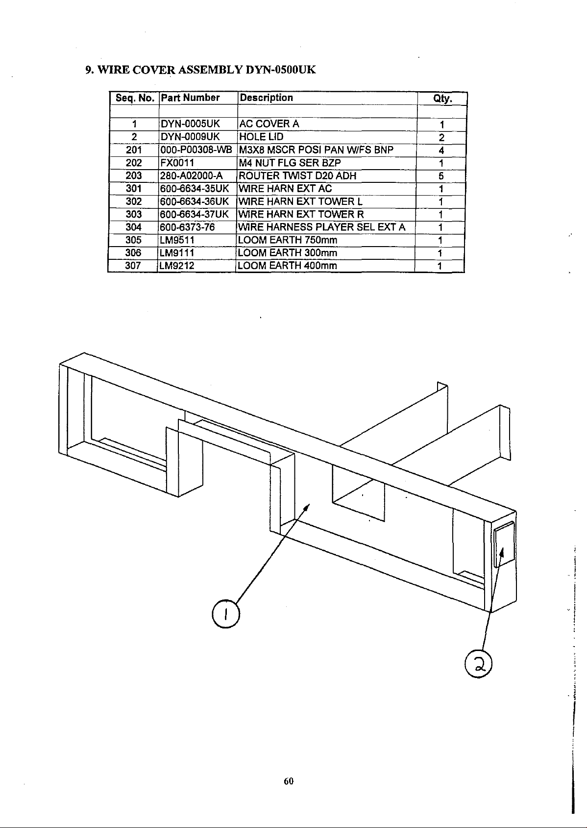
9.
WIRE
COVER
ASSEMBLY
DYN-OSOOUK
Seq.No.
2
201
202
203 280-A02000-A
301
302 600-6634-36UK WIRE
303 600-6634-37UK WIRE
304 600-6373-76 WIRE
305
306
307
Part Number Description
DYN-C005UK
1
DYN-C009UK
000-P00308-WB
FX0011
600-6634-35UK WIRE
LM9011
LM9111
LM9212
ACCOVERA
HOLELID
M3X8
MSCR
M4 NUTFLGSERBZP
ROUTER
HARN
HARN
HARN
HARNESS
LOOM
LOOM
LOOM
POSI
TWISTD20ADH
EXTAC
EXT
TOWER
EXT
TOWER
PLAYER
EARTH
EARTH
EARTH
750mm
300mm
400mm
PAN
W/FS
BNP
L
R
SELEXTA
Qty.
1
2
4
1
5
1
1
1
1
1
1
1
60
I
- !
I
~
I
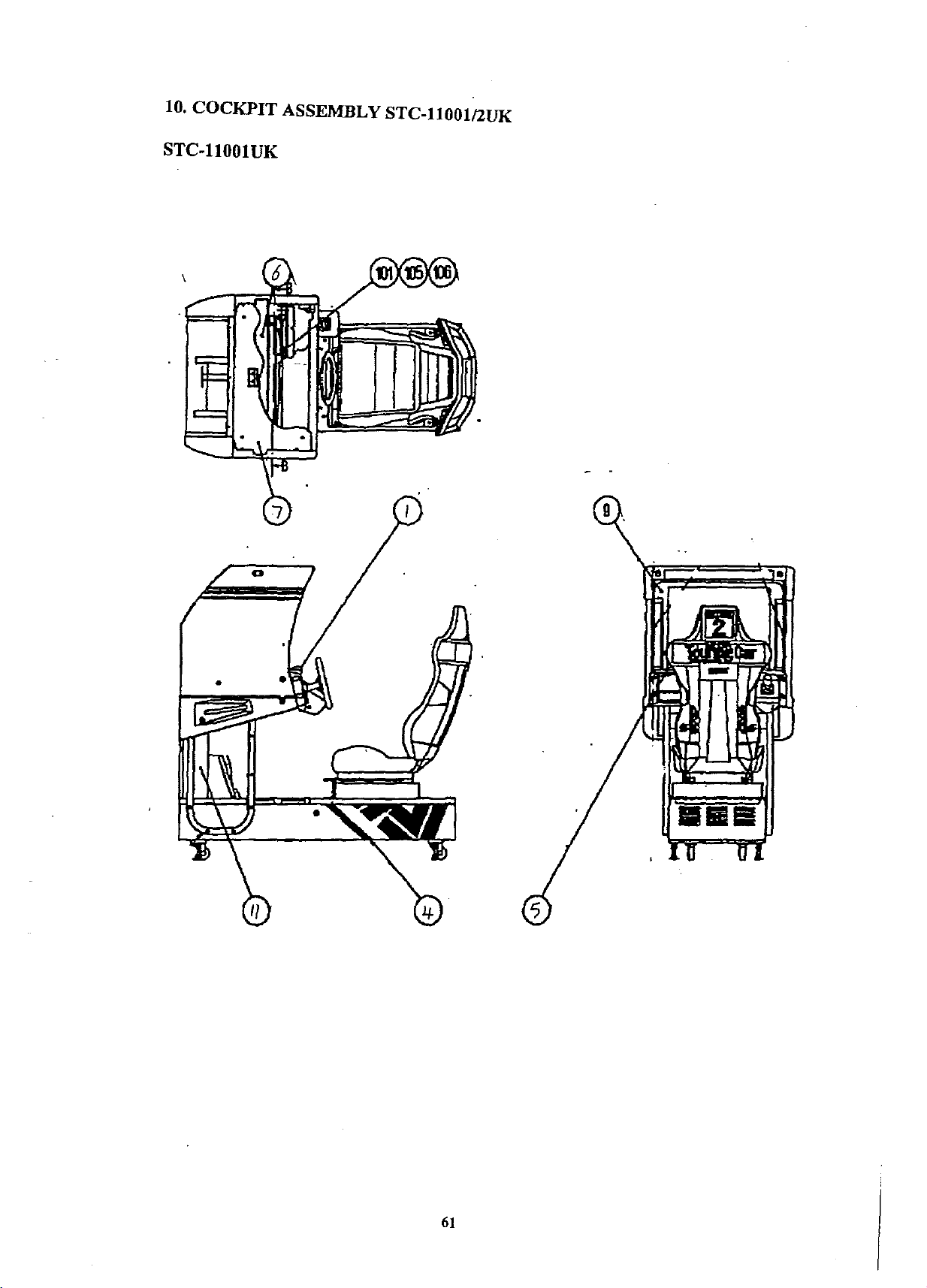
10.
COCKPIT
STC-llOOlUK
ASSEMBLY STC-llOOlI2UK
61

Seq. No. IPart Number
1
STG-12003UK
MSB-2030UK
2
DYN-2040UK
3
4
STC-21001UK
STG-2200UK
5
6
INY-1016UK
7
OYN-1015XUK
DYN-1017UK
8
9 TIR-1067UK
422-0591-01
10
DYN-1013XUK
11
DYN-2016XUK
12
DYN-13OOUK
13
-
RAL-2007
14
RAL-2008
15
144Q-DS0013XEG
16
101
M01029
102
OS1174
103
PP1OO1
280-A0200Q-A
104
105
280-5112UK
106
FX0012
280-A0120Q-A
107
108
LB1096
160H5231-C100
109
1601-ll231-D100
110
111iSTC-2011-A
205
FX0400
1
206
FX0445
1
207
IFS1019
208
000·P00408·WB
212
FX0011
214
FXoo13
LB1034
215
216
FX0402
I
217
000-T00512-0B
218
1000-
T00530-0B
219
iFS1027
1008-B0083Q-OB
221
222
1008-
T00416-0C
225 030-ooo616-SB
FS1018
227
228
FS1014
FX0409
229
230
FS1019
231
FX0302
232
OS1199
233
OS1136
234
FAS-300OO9
235
030-0oo816-SB
236
FX0431
237
FX0404
I
238 iFS1009
239
'030-ooo~~M8X30
301
,6oo-ll634-21
302
1600-Q634-23
303
1600-Q634-28
304
16OO-ll634-29
306
16oo-ll634-34UK
307
16oo-ll373-n-91 IWiRE
ILM9111
308
309
ILM9611
310
,LM9511
IDescription
,
ASSY
CONTROL
ASSY
FLOOR
ASSY
FLOOR
ASSY
MAIN
ASSYSEATTWIN
MONITOR
ROOFLID
MASK
HOLDER
MONITOR
SUB
INSTR
WIRE
COVER
PEDAL
BASE
ASSY
ACCEL&BRAKE
RUBBER
RUBBER
STICKER0MONITOR
ASSYCLRDSPL29TYPE 24K100V 1
CABLE
COLLAR
ROUTER
BUSH
M6WSH
ROUTER
STICKER
EDGING
EDGING
STICKER
M8WSHRFORMA FLTBNP 12
M8X45
M8WSHRSPRBNP 2
M4X8
M4NUTFLGSERBZP i 4
M6NUTFLGSERBZP 4
LABEL
M5X8MSCRPOSICSKBZP 4
M5X12
M5X30
M5WSHR
M8X30
M4X16
M6X16
M6
M8WSHRFORMC FLTBNP
M8X40
M8
M5NUTFLGSERBZP 2
CLIP"P"
CLIP
M8X20
M8X16
M4X12
M4WSHRSPRBNP 4
M4WSHRFORMA FLTBNP
WIRE
WIRE
WIRE
WIRE
WIRE
,LOOM
1
LOOM
1
LOOM
HOLDER
HOLDERL TWIN
TIE,
FORNANAO
TWIST020 ADH 20
FORFSTTV
2500
TWIST012 ADH
PROTECTIVE
NEWTYPE 2
NEWTYPE 1
BASE
SETBNP 2
MSCR
"HIGH
MSCRPOSITH BNP
MSCRPOSITH BNP 2
MSCRTMP PRFBHBNP 4
MSCRTMP PRFTH CRM
BLTWIS BNP 6
WSHR
SETBNP 4
WSHR
ADHESIVE
ADHESIVE
BLT PVC 2
BLTW/S BNP 4
MSCRPOSIPAN BNP 4
BLTWIS BNP
HARN
HARN
HARN
HARN
HARN
HARNESS
EARTH
EARTH
EARTH
PANELTWINM
FRONTUK 1
REAR
BASESTCC
SUPPORT
MASKFST
SHSTC ENG
NYLON
POSIPANWIFSBNP
VOLTAGE"
1900
FORMCFLT BNP 6
SPRBNP 10
MONITOR
EXTCONTPNLB
EXT
SHIELD 1
EXT
UK
BOXUK
UK
RTWIN
100mm
MONITOR
FLATBZP
EARTH
LIDR
64X 38mm 1
FLTBNP 5
25X25MMX15MM
28X28MM
VOLUME
BILLBOARD
PLAYER
300mm 2
1000mm
750mm 1
X 10MM 2
B 1
UK 1
SELEXTB 1
,
i
:
,
:
,
: 1
,
I
,
I
I
I
I
,
,
,
Qty.
1
1
1
1
1
1
1
1
1
1
1
1
1
1
10
4
4
4
12
4
1
14
7
4
10
2
4
12
1
1
1
62
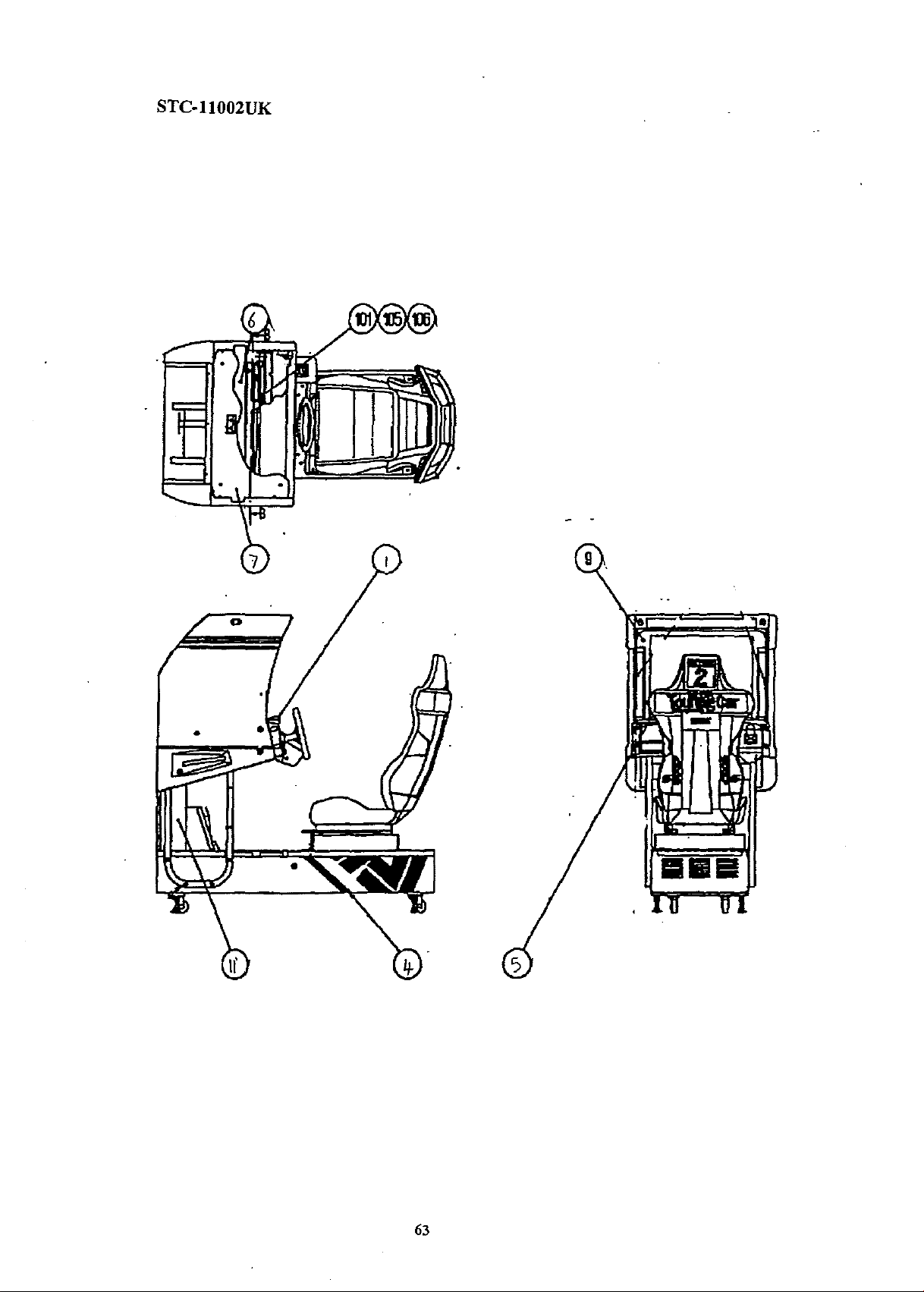
STC-ll002UK
63
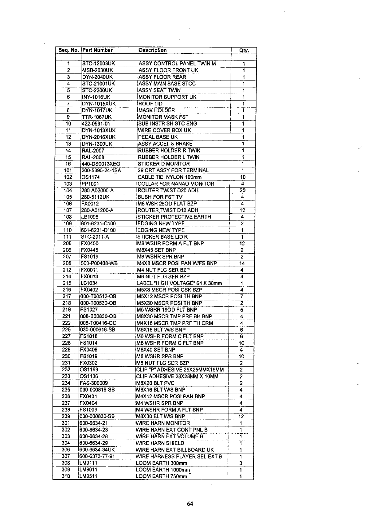
Seq.No. Part Number iDescription
I
1
STC-12003UK
MSB-2030UK
2
3
DYN-2040UK
STC-21001UK
4
5
STC-22ooUK
6
INY-1016UK
7
DYN-1015XUK
8
DYN-1017UK
9
TTR-1067UK
10
422-0591-01
11
DYN-1013XUK
12
DYN-2016XUK
13
DYN-13OOUK
14
RAL-2007
15
RAL-2008
16
44o.DS0013XEG
101
200-5395-24-1
OS1174
102
103
PP1001
104
280-A0200o.A
105
28o.5112UK
106
FX0012
107 28o.A0120o.A 1
108
LB1096
109
1601-6231-C100
1601-6231-0100
110
111
ISTC-2011-A
205
I
FX0400
206
I
-
235
236
237
238
239
301
302
303
304
306
307
308
309
310
FX0445
207
FS1019
208
1000-P00408-WB
212 I
FX0011
214
FX0013
215
LB1034
216
FX0402
21,7
1000-
T00512-0B
218
000-T00530-0B M5X30
219
FS1027
221
008-B0083o.OB
222 008-T00416-0C M4X16
225
030-000616-SB
227
FS1018
228
FS1014
229
FX0409
230
FS1019
231
FX0302
232
OS1199
233
OS1136
234
FAS-300oo9
030-0oo816-SB
FX0431
FX0404
FS1OO9
030-0oo83o.SB
600-6634-21
600-6634-23
600-6634-28
600-6634-29
6oo-6634-34UK
600-6373-77-91
ILM9111
ILM9611
iLM9511
..
SA
IASSY
iASSY
ASSY
IASSYMAINBASESTCC
iASSYSEATTWIN
iMONITOR
IROOFLID
IMASK
IMONITOR
SUB
INSTR
WIRE
COVER
,PEDAL
ASSYACCEL&
RUBBER
RUBBER
STICKER0MONITOR
129
CRTASSYFOR
iCABLE
ICOLLAR
1
ROUTER
,BUSHFORFSTTV
IM6WSH
ROUTER,TWlST
iSTICKER
IEDGING
IEDGING
ISTICKER
IM8WSHR
IM8X45
IM8WSHRSPRBNP
IM4X8
MSCR
M4 NUTFLGSERBZP
IM6NUTFLGSERBZP 4
'LABEL
IM5X8
MSCR
'M5X12
M5WSHR
M8X30
M6X16BLTW/S BNP
iM6WSHR
IM8WSHR
IM8X40SETBNP
M8WSHRSPRBNP
M5NUTFLGSERBZP 2
CLIP"P"
iCLIP
ADHESIVE
IM8X20BLT
IM8X16BLTW/SBNP
IM4X12
IM4WSHRSPRBNP 4
IM4WSHR
,M8X30
IWiRE
,WIRE
IWiRE
'WIRE
·WlRE
'WIRE
-LOOM
LOOM
LOOM
MSCR
BLT W/S BNP
HARN
HARN
HARN
HARN
HARN
HARNESS
EARTH
EARTH
EARTH
,
CONTROL
FLOOR
FLOOR
HOLDER
BASE
HOLDER
HOLDER
TIE,
FOR
TWIST
2500
PROTECTIVE
NEW
NEW
BASE
SETBNP ; 2
"HIGH
MSCR
MSCR
MSCR
MSCR
ADHESIVE
PANEL
TWINM
FRONT
UK
REAR
SUPPORT
MASKFST
SHSTCENG
UK 1
NYLON
FORM
POSI
VOLTAGE"
POSI
POSI
POSI
1900
TMPPRFBHBNP 4
TMPPRFTH CRM
FORM
FORM
UK
BOXUK 1
BRAKE
RTWIN 1
LTWIN
TERMINAL
100mm 10
NANAO
TYPE
TYPE
MONITOR
020 ADH 20
FLATBZP 4
012 ADH 12
EARTH
LIDR
A FLTBNP
PANW/FSBNP 14
64X
38mm
CSKBZP 4
TH BNP
TH BNP 2
FLTBNP 5
C FLTBNP 6
C FLT BNP 10
25X25MMX15MM
28X28MMX10MM
PVC
POSI
PAN
BNP 4
FORM
A FLTBNP 4
MONITOR
EXTCONTPNL B
EXT
VOLUME
SHIELD
EXT
BILLBOARD
PLAYER
300mm
1000mm
750mm
B
UK
SELEXTB
i
I
!
i
I
,
,
1
i
I
,
:
I 2
I
,
:
I
I
,
QIy.
4
4
4
2
1
1
12
2
4
1
7
4
6
4
10
2
2
4
12
1
1
1
1
1
1
3
1
1
1
1
1
1
1
1
1
--
1
1
1
1
1
1
1
64

11.
CONTROL
Seq. No.
PANEL ASSEMBLY STC-12003UK
Part
Number
DYN-1201 STEERING WHEEL (270)
1
2
3 INY-1203 ISTEERING EMLBEM
4 INY-1205UK CONTROL PANEL BRKT
5
6 INY-1204 SHIFT COVER INY
7
8
9
10
11
101 610-0383
102
103
104 280-A02000-A
105 280-A01000-A ROUTER
106 509-5440 PUSH BTN SW IT GRN W/L DC 14V
107
201
202 FX0213
203 008-T00512-0B M5X12 MSCR TMP PRF TH BNP
204 000-T00416-0B M4X16 MSCR POS! TH BNP
205 000-T00416-0CIM4X16 MSCR POSI TH CRM
206 000-P00412-W
207 008-T00516-0B
208 FX0011 M4 NUT FLG SER BZP
209 FX0319 M3 NUT FLG SER BZP
210 000-T00416-0C
301 600-6634-24
302 600-6634-25 WIRE HARN VR
303 600-6634-32
304 600-6634-33 WIRE HARN EARTH MOTOR
305 600-6373-78 WIRE HARNESS PLAYER SEL SW
306 LM9512 LOOM EARTH 750mm
307
DYN-1209 HANDLE COLLAR, DAYTONA
STC-1202-02 CONTROL PANEL COVER
DYN-1223 SHIFT COVER B DAYTONA SEGA
INY-1250 ASSY VIRTUAL
FS1031
117-5164
DYN-0010UK DENOMI PLATE
610-0408
OS1174
OS1181 CABLE TIE BASE 19mmSq SELF/ADH
FX0261 M8 WSHR SPR BZP
LM9322 LOOM EARTH 500mm
Description
1WIN
UK
1WIN
BUnON
M8 WSHR
PLATE START 37x42mm DAYTONA
ASSY HANDLE MECHA W/MOTOR
UP/DOWN SHIFTER AL
CABLE TIE, NYLON 100mm
ROUTER
IM8
NUTBZP
M4X12 MSCR POSI PAN W/FS PAS 3
M5X16 MSCR TMP PRF TH BNP 4
M4X16 MSCR POSI TH CRM
WIRE HARN SHIFTER 1
WIRE HARN EXT MOTOR
250D
1WIST
1WIST
FLT BNP
D20 ADH
D10 ADH
BUnON
Qty.
1
1
1
1
1
1
1
1
2
1
1
1
1
10
5
2
1
2
5
5
,
3
3
4
2
2
8
1
1
1
1
1
1
65

2
66

12.
CONTROLPANEL
Seq. No.
Part
COVER
Number
STC-1202-02
Description
QIy.
1
2
3
4
5
6
7
201
202
DYN-1214-A
RAL-1205-A
DYN-1214-C
DYN-1214-D
DYN-1214-E
DYN-1203
422-0593-01
047-PA3207-6
060-F00300
CONTROL
METER
DESIGN
DESIGN
DESIGN
TWEETER
PLAY
RVT
M3
PANEL
PLATE
PLATE
PLATE
INTR
OPEN
FLTWSHR
PANEL
NET
SHTSTCTWINENG
TYPE
COVER
TACO
OIL
WATER
METER
METER
METER
AL3.2x7.6
BLANK
TWIN
TWIN
TWIN
1
1
1
1
1
2
1
•• •
•
67

13. VIRTUAL BUTTON ASSEMBLY INY-1250
Seq. No. Part
INY-1251 VR SW BRACKET
1
171-64788 PC BD LIGHTING SWX5
2
101
102
103
104
212-5205-12
509-55600Y
509-5561-R PB
509-5561-8 PB
Number
Description
CONN
P8
JST
M 12P RTA
SWW/L
SWW/L 6V 5L R 1
SWW/L 6V 5L S 1
6V 1L R
Qty.
1
1
1
1
I
68

14.
MONITOR
Seq. No.
HANDING
Part
Number
KIT
STC-7000UK
Description
Qty.
1
2
3
4
5
6
201
STC-1031
STC-1031-A
STC-1061
STC-1061-A
DYN-1032UK
SDW-0001UK
00o-P0040B-W
COVER
COVER
COVER
COVER
MASKBRKT
BLIND
M4XB
PANEL
PANELLBLANK
PANEL
PANELRBLANK
CAPUK
MSCR
L 1P
R2P
POSI
PAN
W/FS
PAS
1
1
1
1
4
12
4
69

15. HANDING
Seq. No.
KIT
STC-6000UK
Part
Number
Description
QlY.
STC-0401UK AC
1
211-5479 CONN OPT JOINT PNL-TOCA150
2
3 EP1344
EP1334 FUSE HOLDER 20mm 10A 240Vac
4
EP1302
5
EP1303 SWITCH ROCKER DPST 10A 250Vac
6
514-5078-10000 FUSE 5X20 CERAMIC SB 10000mA
8
10
11
12
101 LB1000
102 LB1037
103
104 LB1088
105
106 LB1099 STICKER FUSE TYPE F
107 LB1100 STICKER FUSE TYPE T 1
108 LB1098 STICKER SWITCH
201 FX0037 M4X12 MSCR POSI PAN BZP
202 FX0243
203
204 FX0011 M4 NUT FLG SER BZP
205 FX0029 IM3X10 MSCR POSI PAN BZP
301 600-6373-60UK
302 600-6775-102 WIRE HARN AC BRKT (MAIN)
303 LM9111
514-5078-5000
STC-1605
STC-2202
LB1087
LB1096 STICKER PROTECTIVE EARTH 4
FXOO09
BRKTUK
FILTER EMI 10A BLP
,
EUROSOCKET FUSED
FUSE 5X20 CERAMIC SB 5000mA
SEAT REAR COVER
ISEAT REAR COVER 2P
LABEL 5A (AC BRKT FUSE)
LABEL 10A FUSE
STICKER FIBRE CABLE RX
STICKER FIBRE CABLE TX
M4 WSHR SPR BZP
M4 WSHR FORM A FLT BZP 4
WIRE HARN AC UNIT SUB
LOOM EARTH 300mm
1-0
10A
250Vac
-
I
I
!
I
,
i
I
I
2
4
1
2
1
1
1
2
1
1
2
1
2
2
1
1
4
4-
2
8
1
1
2
70

ACUNITMAIN
0
ACUNITSUB
[£]
U
0
0
0
r------
{~
,@
,
, ,
I
, ,
,
, ,
, ,
,
,
,
,
'@
fQ'
L
________
-,
@,
@'
0
,
,
,
,
I
,
,
...J
0
[£]
{Q'
0
0 0
OJ
0
CJ
0
0 0
(Q'
0
71
0
D
-
0

16. MAIN BASE ASSEMBLY STC-2100lUK
Seq. No.
2 STC-4400
4 MP1208
5
6 MA1007
7 MA1011
101 260-0011-02
102
105 OS1174
107
108 LB1084
109 LB1096
110 STC-2002
111 STC-2003
201
202 FX0301
203
204
205 FX0320
206 FX0245
207 OS1195 RIVET SNAP MOSS SR1811 8
208 IFX0019
209 FX0011 M4 NUT FLG SER BZP
210 FX0201 M8X16 SET BZP
211 FX0261 M8 WSHR SPR BZP 16
212
213
214
215 OS1221 FOAM STRIP, OPEN CELL,
216
301
302
303
304
305
306
307
Part
Number
MSB-1121UK MAIN BASE UK
1
3 STC-4500UK
INY-1014UK MONITOR STAND UK 1
600.,6275-0150 ASSY FIBER OPTIC 150150CM 2
FN1012
FX0040
FX0037
FXOO09
FX0408
FS1014 M8 WSHR FORM C FLT BNP 8
FS1019 M8 WSHR SPR BNP
280-A02000-A ROUTER TWIST D20 ADH 10
600.£373-12-91UK WIRE HARN AC FAN REAR UK 1
600.£373-35UK WIRE HARN AC FAN UK 1
600.£634-22
600.£634-26 WIRE HARN EXT TOWER 1
600.£634-27 WIRE HARN EXT VOLUME A 1
600.£634-38 WIRE HARN EXT RGB B
600.£775-009 WIRE HARN MAIN BASE 2
Description
ASSY MAIN BD BASE
ASSY ELEC BASE
BRKT FAN DAYTONA
CASTOR SWIVEL 63mm NYLON
FOOT ADJUST M16X95 TYPE C 4
AXIAL FLOW FAN AC100V
CABLE TIE, NYLON 100mm 10
MESH GUARD METAL 120mm FAN
LABEL AC VOLTAGE SET TO: 1
STICKER PROTECTIVE EARTH
STICKER BASE L
STICKER BASE R 1
M4X25 MSCR POSI PAN BZP 4
M4 WSHR
M4X12 MSCR POSI PAN BZP 2
M4 WSHR FORM A FLT BZP
N10X1/2"
M5 WSHR FORM A FLT BZP 4
M4 WSHR S/PRF BZP 2
M8X60 SET BNP
WIRE HARN EXT
1600
FLT BZP 4
SITAP HEX BZP 8
CONT
50.£OHz 2
I
,
---
SEUAD
PNL A 1
Qty.
1
1
1
1
4
2
3
1
2
1
16
8
8
0.1
1
1
72

0---f-.<
12
n-
o I

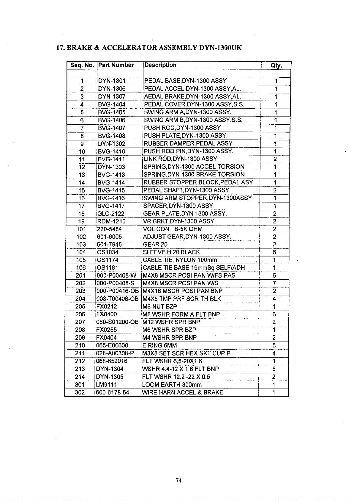
17. BRAKE &
Seq.
No.
1
2
3 IDYN-1307 IAEDAL BRAKE,DYN-1300 ASSY,AL. I 1
-4
--------'------
5
6
7 BVG-1407
8
9
10
11
12
13 BVG-1413
14 BVG-1414
15
--
17
18 IGLC-2122
19
101 1220-5484 IVOL CONT B-5K OHM
102 1601-6005
103 '601-7945
104
105
106
201 1000-P00408-W M4X8 MSCR POSI PAN W/FS PAS 6
202 000-P00408-S M4X8 MSCR POSI PAN W/S
203
204 008-T00408-0B M4X8 TMP PRF SCR TH BLK
205
206 FX0400
207 1060-s01200-0B
208
209 IFX0404 M4 WSHR SPR BNP
210 1065-E00600 IE RING6MM 5
211 1028-A00308-P
212 1068-652016 FLT WSHR 6.5-20X1.6 1
213 iDYN-1304
214 IDYN-1305 IFLTWSHR 12.2 -22 X 0.5
301 iLM9111 LOOM EARTH 300mm 1
302
ACCELERATOR
Part
Number
_I
ASSEMBLY DYN·1300UK
Description
- Qty.
i
IDYN-1301 PEDAL BASE,DYN-1300 ASSY
IDYN-1306 PEDAL ACCEL,DYN-1300 ASSY,AL.
BVG-1464---
'BVG-1405
BVG-1406
BVG-1408
DYN"-'1302
BVG-1410
,
IBVG-1411
IDYN-1303
BVG-1415 IPEDAL SHAFT,DYN-1300 ASSY.
BVG-1417
,RDM-1210 VR BRKT,DYN-1300 ASSY.
IOS1034 ,SLEEVE H 20 BLACK
IOS1174 ICABLE TIE, NYLON 100mm
IOS1181
1000-P00416-0B iM4X16 MSCR POSI PAN BNP
iFX0212
---
IFX0255
1600-6178-54
TPEDALCOVER,DYN-1300 ASSY,S.S.
_.
-
-~._--
,SWING ARM A,DYN-1300 ASSY.
ISWING ARM B,DYN-1300 ASSY.S.S.
,PUSH ROD,DYN-1300 ASSY
IPUSH PLATE,DYN-1300 ASSY.
IRUBBER
]PUSH
-JUNK
ISPRING,DYN-1300 ACCEL TORSION
ISPRING,DYN-1300 BRAKE TORSION
TRUBBE-R-STOPPER BLOCK,PEDAL ASY
ISWING ARM STOPPER,DYN-1300ASSY
:SPACER,DYN-1300 ASSY
.+GEAR PLATE,DYN 1300 ASSY.
IADJUST GEAR,DYN-1300 ASSY.
iGEAR20
CABLE TIE BASE 19mmSq SELF/ADH 1
M6
M8 WSHR FORM A FLT BNP 6
M12 WSHR SPR BNP 2
M6 WSHR SPR BZP 1
IM3X8 SET SCR HEX SKT CUP P 4
JWSHR
WIRE HARN ACCEL
DAMPER,PEDAL ASSY
ROD PIN,DYN-1300 ASSY.
ROD,DYN-1300 ASSY.
NUTBZP
4.4-12 X 1.6 FLT BNP 5
& BRAKE
1
1
1
!
1
1
1
i
1
,
1
1
I
1--
1
2-1
I
,
1
,
1
2
I
116 BVG-1416
1
2
2
2_
I
2
i
2
._--
I
6
i
1
7
I
,
2
._--
4
1
--
2
2
I
I
1
74

18.
FLOOR
Seq. No.
REAR
Part
ASSEMBLY DYN-2040UK
Number
Description
Qty.
1
2
3
4
5
6
7
101
201
202
204
205
DYN-2041UK
RAL-XXXX-8UK
DYN-2043UK
DYN-2044UK
DYN-2045UK
DYN-2006UK
.
DYN-2049UK
CH1194
FX0302
031-000530-0C
000-T00420-0C
FX0163
2
FLOOR
FLOOR
FLOOR
FLOOR
FLOOR
HINGE
NUT
LOCK
M5NUTFLGSERSZP
M5X30
M4X20
N8X1/2"
REAR
DAYTONA
EDGE
EDGE
EDGE
EDGERRIGHT
480
PLATE
RADIAL
CRG
MSCR
SITAP
RF
R R
RLEFT
DAYTONA
(SEAT)
WITH
SLT
POSITHCRM
POSI
DAYTONA
DYNUK
CRM
DAYTONA
DAYTONA
TONGUE,
FLG
SZP
RALLY
•
1
1
1
1
1
1
2
1
8
8
6
4
o
o
A
•
•
•
•
•
•
•
•
•
76
7

19.
FLOOR
FRONT
MSB·2030UK
Seq. No.
1
2
3
4
5
7
8
201
203
Part Number Description
MSB-2031UK
DYN-2032XUK
DYN-2033UK
DYN-2034XUK
DYN-2035XUK
DYN-2037XUK
RAL-XXXX-3UKlB
031-D00530-0C
000-T00420-0C
FLOOR
FLOOR
FLOOR
FLOOR
FLOOR
WATER
ASSY
FLOOR
M5X30
M4X20
FRONTUK
EDGEFFRONT
EDGE
EDGE
EDGEFRIGHT
DEFLECTOR
CRG
MSCR
FR
DAYTONA
F LEFTUK
FRONTUK
BLT CRM
POSI
THCRM
UK
UK
(BULK)
Qty.
1
1
1
1
1
1
1
3
8
•
•
•
oo
•
•
o
77

20.
SEAT
ASSEMBLY STC-2200UK
Part
Seq. No.
NumberIDescription
!
STC-1650
1
STC-1601-A UPPER SEAT BLANK
2
3 STC-1601-B UPPER SEAT INSERT 1
4 STC-1602-A LOWER SEAT BLANK 1
5 STC-1602-B
6
7
8
9 STe-1607
10
11 STC-1609
12 STC-1610
13 STC-1611
14 STC-1612
15 STC-1613 SAFETY GUARD F
101 601-7942
102 601-7981
103 130-5159
105
106 1601-6563-100 BUSH 2.4T
107 280-5297 SCRIVET 8 1K31 6
108
109
110 OS1235
111 OS1234 ADHESIVE TAPE 3M 927 50mm WIDE 3.5
112 IOS1174 CABLE TIE, NYLON 100mm 3
113
201 000-P00410-W M4X10 MSCR POSI
202
203 030-000816-S M8X16
204
205 FX0213 M8
206 FX0261 M8 WSHR SPR BZP 8
207 FX0258
208 FX0155
210
211 FX0301 M4 WSHR
301
302
STC-1603 SEAT BASE 1
STC-1604
STC-1606
STC-1608
601-13563-188 IBUSH 2.4T 1
OS1004 DRAFT EXCLDR 4 X7MM BLK 1 MTR. 0.75
OS1236 SURFACE CLEANER 3M VHB 0.25
OS1181 CABLE TIE BASE 19mmSq SELF/ADH 5
030-000850-SB
000-T00408-0B M4X8 MSCR POSI TH BNP 8
000-T00616-0B M6X16 MSCR TH POSI BNP 4
600~774-016
600~77
4-017 WIRE SEAT EXT
'ASSY SUB WOOFER STCC
LOWER SEAT INSERT
SEAT FRAME
SEAT MOUNT TRAY
SP MOUNT BRKT 2
SPEAKER NET L
SPEAKER NET R
SAFETY GUARD
CABLE BEAR BRKT 1
iPROTECT RUBBER 2
SEAT RAIL AL L 1
SEAT RAIL AL R 1
GULL BOX SPEAKER 8 OHM 5W 2
ADHESIVE TAPE 3M 950 50mm WIDE 3.5
PANW/FS
M8X50 BLT
NUTBZP
M8 WSHR
N6X1/2"
WIRE HARN SPEAKER EXT 1
W/S
BNP
BLTW/S
SITAP POSI FLG BZP
PAS 4
220D
FLT BZP
160D
FLT BZP
Qty.
1
1
1
2
1
1
1
1
1
1
i
14
8
8
20
8
12
1
78

o
---------1
c__ _ -_ -
O
I
EXTERNAL
----
VOLUME
u-p connector pin assign label
5 1
-
-r~~-;:Gli-t~-;~-~;-----~a":";r;:W-Lml:;;y.im-,~m-~:---
--
0
1
I I0 I
l_
__.:.
-:
i I
~"'l'
0 !
J
I:I:CI
15
*
Connect
only
swi
BIA~IA~I
11
tch
to
DEI.!

_.
-..:..-~.=
1'69
ZB9
!'E:9
_.
1/
..
;>-
-
I
I
_
...
_--=:J
"\
•
I
I
•
~;
:r-
:'1
~
--_._--
00
oo
_.
••
'0
'l'
'"
<D
x
<
"
SZ~
I-~
i
.-
ij
I
~
:1
~
I·t
:1
,
,
I
·
:
•
·
·•
•
._----------
-
,--
------------
•
I
i
.
0
n
0
0
0
.. -
f"
...
...
-t
-t
(Il
'"
..
III
f"
...
...
--'--
·
·
·
:
A-.i
..
"(!r4.
-
.--;-
Ij)
A
m
N
Ii.
o
III
Z
09
ol. I
I-..--·-L"S""'Z---

R.
<D
<ID
~
®
®
®
cr>
®
<ID
@
®
@
©>
@
~
~
®
GAIN
G.
GAIN
B.
GAIN
BRIGHT(VR481)
H.SIZE(VR455)
H.
HOLD
H.
POSI(VR45
V.
SIZE(VR353)
V.
HOLD
V.
POSI(VR35
R.
BLK
G.BLK
B.BLK
PCC
PHASE(VR453)
PCC
AMP
H
SUB
HOLD(VR343)
V.LIN
(VRI5J)
(VRI52)
(VRI53)
(VR342)
J)
(VR341)
J)
(VRZO
I)
(VR202)
(VRZ03)
(VR454)
(VR354)
Function
Red
signal input gain, to be
Green
Blue
. Brightness, to be bright
Horizontal size, adjust a video horizontal size.
Horizontal synchronization holding, adjust a
right
Horizontal position, adjust a horizontal raster position.
Vertical size, adjust a video vertical size.
Vertical synchronization holding, adjust a
and
Vertical position, adjust a·vertical
Red
when
Green
when
Blue
when
Pin-cushion control
deflect distortion.
Pin-cushion control
Horizontal synchroniation
horizontal synchronization holding
Vertical linearity, adjust a spread the
signal input gain, to be
signal input gain, to be
and
bottom
signal blanking. adjust a cut-off point, to be
turn
signal blanking. adjust a cut-off point. to be
turn
signal blanking. adjust a cut-off point, to be
turn
adjustment
left
of video
of video
on
right.
on
right.
on
right.
deep
red
when
turn
deep
green
deep
blue
when
turn
on
image.
image.
PHASE,
AMP,
adjust a
adjust a horizontal deflect distortion
sub
holding
phase
at
when
when
right.
drifting
raster
at
mode
position.
for horizontal
15KHz
I.
upper
turn
drifting
part of
on
turn
on
mode.
right.
on
right
right.
out to
out to top
deep
red
deep
green
deep
blue
adjust a
image.
@
@
@
@
@
@
@
CN4ffi
CN404
CN402
CN401
CN302
FOCUS
SCREEN
See
Change
Change
Fig
Change
@
CN402
inserted
normal
to
@
CN402
inserted
to reverse
Focus
Screen, adjust a best position.
of frequency connector. correspond to
of frequency connector, correspond to
of vertical polarity the deflection
@
CN302
normal
horizontal
reversed picture picture
• adjust a best position.
normal
picture vertical reversed picture
and
vertical
@
horizontal reversed
24.83KHz.
15.
75KHz.
yoke.
CN302
reversed

5.Power.
6. Magnetism.
When working on or near
from the
If
picture and colour will
Demagnetisation coil fitted to the monitor,
mains at the wall.
a magnetofany sort is placed in the vacinityofthis product then the
this product ensure that the power is disconnected
be distorted. This is rectified using the
7. Static Electricity.
If
the screen is touched then a small static charge is felt. This is not a
problem and does not harm the human body.
•

PRECAUTIONS
I. Shock. Do not subject this product to shock when in transit, this may cause
damage.
2. High Voltage Point. Under no circwnstances touch any
If
there is any reason to touch any partsofthis product ensure
27K
volts
.Mx.29K
will cause damage over long periods.
volts
<>
Dangerous
high
Assembly
-'
3. Volume Adjustments.
product.
that the power has been disconnected from the mains at the wall.
voltage point
MAIN
Board
0-
\,./
Do not adjust the Volume settings on this product.
If
any Volume must be adjusted follow the correct procedure as improper
adjustment
of
the High Voltage areasofthis
•
Assembly
max.·IOK
CRT/D
Board
voIts
4. High Temperature
Points
<>
Dangerous
high
Assembly
Under no circwnstances should f1anunable material come into contact with
this as there are certain points that run at a high temperature.
material should come into contact with these points then a fire or electric
shock may be caused.
teDlperature
MAIN
Board
A
\,.,.1
nax.
point
75'C
Assembly
max.
*
Condition:The
temperature
CRT/D
at
If
flammable
Board
8O'C
surroundings
4crC

_
Red
input
Q.Green
Blue
" Synchronization
input
-----------------------
_Power
Input
input~
input '.~
H.HOLD
H.POSI
l.-
rI
'vv
H.HOLD
Power
0801-Q800
Degaussing
Circuit
Block
R.
GAIN
G.GAIN
B.GAIN
Video
Circuit
ICIOI
~
~/
) ).
;.
..
R.BLK
G.BLK
Synchronization
Separator Eraser
Circuit
IC102
ampl
ifier
~<
;.
(
B.BLK
BRIGHT
Diagram
I-I-I--
II
/
Branking
Circuit
CRT!D
Circuit
Board
Ql02
J::
~1-!~~Q3--
-,
Horizontal,Vertical Vertialoutput
Oscillator Circuit
IC301
~
Horizontal
Driver Circuit
Q403
Regulater
-------------------------_.
Circuit
IC302
liar
izontaI
Output
Circuit
0404
Deflection coiI
=~X
-'-~
.
--
---
V.SIZE
V.
LIN
V.POSI
,--
High
Transformer
T402
Change
Frequency
CN404:
CN4C6:24KHz
of
15KHz
Primary:Secondary
CRT
~J~
'--'
-
.-
0
"
...
Q)
.,
.,
'"
..
'"
Q)
""
--,
---
,
,
,
,
,
,
,
,
,
,
,
,
,
,
,
,
,
,
,
,
Voltage
,
,
,
,
,
,
,
,
,
,
,
,
,
,
,
,
,
,
,
,
,
,
,
,
,
,
,
,
,

Timing
Chart
o Horizontal
MODE
(
Time
Chart ( UNIT:
I )
15.75KHz
)lsec
)
Display
Term
51.00
63.50
, , ,
o Verti'caI ' ,
Video
S~nchronizing
Signal . , :
s:~~~P:~-----------------1
J
I
~5Vp:12
_ _____
. I I I
Time
Chart
U~-·--·l---------~'------'U
..
, , ,
I :
:
If
, , ,
l.
."
25 :
UNIT:msec
(
,
Display
14.00
16.50
)
Term
'":,"1.00·
0.25:
il' I::: I
. ,
(
MODE
2 )
24.83KHz
o Horizontal
,
,
,
: e
o Vertical
Video
S~nchronizing
Signal ,
s:~~P:~l-----------------1
~j
I
~5Vp-p
____
Time
Time
Chart
U
IE
Chart ( UNIT:zzsec )
UN
IT:
(
Display
,
::,
..:=!'
I.
03
'
I
,
I
I
:,..
..
>--------_-=..:.:..:..:::..-_----~~
I
41.00
msec
15.74
17.38
)
Term
, ,
, ,
: 3.00 I
",
I
'i
, ,
, ,
, ,
I I
:O.16;
=-
I C..,
, :
.,.
:

4:
Adjustment
Position
VR
BOARD
MAIN
BOARD
----------
Side of
Casing
Adjustments
H.HOLD
H.SIZE
H.
POSITION
R.GAIN
G.GAIN
B.
GAIN
V.HOLD
V.SIZE
V.
POSITION
BRIGHT
R.BLK
G.BLK
B.BLK
PCC
PHASE
V.LIN
CN302
CN401,
CN404.
CN402
CN4ffi
FOCUS
SCREEN
Description
Horizontal Synchronization
Horizontal
Amplitude
Gain
Holding
Horizontal Position
Red
Signal input
Green
Blue
Signal input
Signal input
Vertical Synchronization
Vertical
Amplitude
Gain
Gain
Gain
Holding
Gain
Vertical Position
Brightness
Red
Signal Cut-off
Green
Blue
Signal Cut-off
Signal Cut-off
Horizontal Deflection Distortion
Phase
Distortion
Vertical Linearity
Function
Function
Function
of
of
of
Reverse
Reverse
Change
Polarity
image
Frequency
(CN404:15KHz!CN4ffi:24KHz)
Focus
Cut-off Point
Adjustment
Adjustment
5.
Environmental
A.
Operational conditions
B.
Storage conditions
C.
Drop
D.
E.
shock
AC
line noise
Vibration
resistivity
resistivity
resistivity
6. Safety requirement
Temperature
Relative
Humidity
Temperature
Relative
40cm
No
app
lied
No
abnormality permitted
with the
Humidity
(at
pullout
by
max.
packege
permitted
noise simulator.
acceleration of
30 minutes.
To
be determined
D'C
to
~
-lD'C to
~
dropped
when
upon
negotiation.
4D'C
70%
6CrC
000/0
from
500Vp-p
when
st
4D'C
bottom)
is
a vibration
IG
applied for

B.
Synchron
Horizontal Synchronizing
Load
Vertical
C.
CRT
C-I Raster Non-linearity
c-z
C-3
izinsUnit
Range
Range
Screen
Raster Distortion
Mis'convergence
Unit
MODE
1
15.75KHz±500Hz
to
62
55
Hor
Vertical s 8%
Keystone
Barrel/Pin-cushion distortion
lnclination
Measure
circle
than
Hz
izontaI
the
specified
15
minutes
Distortion
MODE
24.83KHz±500Hz
to
55
;;;;
8%
;;;;
;;;;
2'
convergence
below,
following turning
62Hz
3%
value
after
2
;;;;
with
heating
in
on.
3%
15mm
more
C-4
C-5
C-6
C-7
Color
Resolution
Size
Weight
Purity
and
of Display
Position
Measuring
point
-
C 0.8
r,B,L,R
TML,
TMR
BML,
BMR
TL,
TR
BL,BR
Satisfactory
image
demagnetizer.
Condition:
640
According
but negotiable.
approx
signals,
(dot) X
Standard(with
X
1.5
2.5 2.5
3.0 3.0
image
CRT
the
to color
38Kg
shuld be
after
fluorescent screen facing
territorial
400
(I i
monitor
/ net.
all
the color
y
0.8
1.5
produced
degaussing with a
magnetisminJapan.
ne)
specification,
at
at
max.)
turn
stick
west,
on

1.
Input Unit
A.
A-I
A-2
A-3'
B.
B-1
B-2
B-3
Input
Power
Volta&e
Frequency
Power
Input
Connector
Connector
Description of
SUpply
SI&081
Specifications
Supply
to outsido
on
board
Si&nals
110V
AC
50 / ffiIIz
approx
AMP
15P
Signa
ls
De&alJSs
Power
IIousin&
SUpply
±
lIClf
U-P
10"/0
Connector
H6P-SHF-IM
VIIR-7N
:
VIIR-3N
1'76.DH
U-P
Pin
11
2.
Display Unit
A.
Display
Connector
No.
I
2
3
4
5
6
'7
8
9
10
to
15
Tube
Input
Red
Video
Green
Blue
Composit
(Horizontal
Video
Video
GND
Input
NC
De&aussing
NC
Power
Si&Jfuls
SI&081
Simal· libiteLeve
Si&08l
Synchronizing
Synchronizing
Si&nal
Si&08l
2.5Vp-p
Black
Ivp-p to
Pulse'li'idth
Ground
see
Not
Switch
A68KVL'74X
29inch 1I0' Deflection
Connect
Not
Specifications
to
5Vp""P
1
Level
5VP""P
A-I.A-2
Used
to
De&aussing
Used
(SAlrlSUNG
Pos
Itve
:a
5V
DC
OVDC
Negative Polarity
3,1..(
s to
'7,1..(
s
Specificatioil
S"itch
LIAnE)
Color
CPT
Po
larJ
ty
B.
Scanning
3. Electrical
A.
lma&e
A-I
IIl8&e
A-2
Band
Peformance
Amplifier Unit
Amplifier
Width
Gain
Non Interlace
j;; DlB
j;;
l!MIz
at-3dB

PAGE
INTEN·TIONALLY
BLANK
LEFT

14. DETAILS OF SANWA MONITOR
103

PAGE
INTENTIONALLY
BLANK
LEFT

PRICE OF PLAY SETTINGS FOR HOLLAND
SWITCH
DIP
2
3
1 1
IGPlay
io Play
IG Play
2G Play
2G Play
2G Play
3G Play
3G Play
3G
~
Play
4G Play
4G Play
5G Play
5G Play
NO BONUS
2.5G = 3
2.5G = 3
NO BONUS
5G=3
5G=3
NO BONUS
5G~2
5G=2
NO BONUS
~3
lOG
NO BONUS
lOG = 3
5G=6
5G=7
IOG~7
IOG~
OFF
ON
OFF
ON
OFF
ON
OFF
ON
5
OFF
ON
OFF
ON
OFF
OFF
OFF
ON
ON
OFF
OFF ON
ON
ON
OFF
OFF
ON
ON
OFF
OFF
OFF
OFF
OFF
ON OFF OFF
ON
ON
OFF
OFF ON OFF
OFF ON
OFF ON
ON
OFF
OFF
OFF OFF
OFF
OFF
OFF
OFF
OFF
OFF
OFF
OFF
OFF OFF
ON
OFF
OFF
OFF
ON
OFF
6G Play
6G Play
8G Play
8G Play
lOG Play
lOG Play
NO BONUS
15G~
3
NO BONUS
20G = 3
NO BONUS
20G=3
FREE PLAY OPTION
I Meter Pulse = O.5G
Coin I
~
NfU,
Coin 2 = 5G,
ON
OFF
ON
OFF
ON
OFF
ON
ON
OFF
ON
OFF
ON
OFF ON
ON
ON
OFF
OFF
ON
ON
ON
OFF
OFF
ON
ON
Coin 3 = 2.5G,
ON
ON
OFF
OFF
OFF
OFF
OFF
ON
ON
ON
ON
Coin4~1G
ON
ON
ON
OFF
OFF
OFF
OFF ON
OFF ON
OFF
ON
OFF ON
OFF ON
OFF ON
OFF ON
OFF ON
ON
ON
101
 Loading...