

Page 1

1ST PRINTING OCT 01
www.seuservice.com
Universal Kit
Kit Installation Instructions &
Service Manual for
ROM & GD ROM SYSTEMS
Switchable FROM High Resolution 31K
TO Standard (Low) Resolution 15.75K.
1 - 2 PLAYER GAME
SEGA ENTERPRISES, INC. USA
MANUAL NO. 999-1311
Page 2

VISIT OUR WEBSITE!
Page 3

Virtua Tennis 2
Sega Naomi System
Kit Contains List
Part #
400-5397-01
838-13616
560-5407-UL
838-13683-93CV1
600-7141-200
600-7009-2500
840-0080D-01
600-7247-500
999-1348
999-1326
999-1325
Desc
NAOMI POWER SUPPLY
AUDIO POWER AMP 2 CH
AUDIO XFORMER 120V
JAMMA I/O BD (NAOMI)
USB CABLE
VGA VIDEO CABLE
ASSY CASE PC1 DIMM BD
CABLE SCSI TYPE 2 500MM
SERVICE SWT BRKT ASSY
JOYSTICK, COMP. BLUE
BUTTON, COMP. GREEN
Qty
1
1
1
1
1
1
1
1
1
2
2
999-1329
999-1327
999-1341
SWITCH, PB LARGE
BUTTON, COMP. BLUE
CNTRL PNL (METAL PLT)
2
2
1
1
www.seuservice.com
Page 4

Virtua Tennis 2
Sega Naomi System
Kit Contains List
Part # QtyDesc
999-1343
999-1344
999-1347
999-1345
999-1346
999-1342
999-1349
999-1350
999-1351
CNTRL PANEL (NAOMI)
CNTRL PANEL (STANDARD)
DECAL SIDE ART
INSTRUCTION SHT (PLAYER)
INSTRUCTION SHT (BUTTON)
MARQUEE AR T
DECALS (BTTNS -TOP SPIN)BL
DECALS (BTTNS-SLICE SPN)GR
DECALS (BTTNS-LOB SHT)WHT
1
1
2
1
1
1
2
2
2
www.seuservice.com
2
Page 5

DESIGNED RELATED PARTS
Marquee Art ---- 999-1342
Instruction Sheet (Player) ---- 999-1345
Instruction Sheet (Button Controls) ---- 999-1346
Control Panel Overlay ---- 999-1344
3
www.seuservice.com
Page 6

Decals Side Art ---- 999- 1347
Control Panel Overlay ----- 999-1343
Decals-Buttons -Top Spin (Blue) 999-1349
Decals-Buttons - Slice Spin (Green) 999-1350
Decals-Buttons - Lob Shot (White) 999-1351
www.seuservice.com
NOT PICTURED
4
Page 7

Feb 9. 2000
120
SERVICE BULLETIN
SEGA Service Department http://www.seuservice.com
45133 Industrial Drive Phone: 415.701.6580
Fremont, Ca. 94538 Fax: 415.701.6594
SPECIAL NOTICE FOR
ALL SEGA NAOMI KITS
PROBLEM:
The SEGA Naomi Game kits are actually ‘JAMMA Dependent’. What this means exactly is they will only
install into existing JAMMA Cabinets. If an operator tries to install these kits into a Non-JAMMA cabinet,
they will first have to bring the wiring up to JAMMA Standards.
SOLUTION:
° Step 1 Disconnect the games original DC Power Supply. You may only use the power supply provided
with your kit. Be sure to set the voltages going to your Game BD to 5.1 and 3.3 volts DC to assure proper
operation ( Measure on Square Connector at Game BD. Yellow = 5vdc / Brown = 3.3vdc / White = Gnd )
° Step 2 You MUST USE THE COIN METER SUPPLIED WITH YOUR KIT to assure proper Coin
acceptance. A minimum 18 Gauge wire should be used from the Coin Meter 1 output line on your
JAMMA Harness. The 5vdc ( Yellow ) wire found in the wiring bag of your kit MUST BE USED for the
supply voltage to the meter.
Not following the directions provided herein may cause your game to malfunction.
All electrical work should be performed by the site’s Serviceman or Technician.
In order to prevent an electric shock and short circuit, be sure to turn power off before performing
work or touching the interior parts of the product.
Be careful so as not to damage wirings. Damaged wiring can cause an electric shock or short circuit
accident.
Do not touch places other than those specified. Touching places not specified can cause an electric
shock or short circuit accident.
If you have any questions please contact the SEGA Service Department at the numbers given above.
5
www.seuservice.com
Page 8

INSTALLATION INSTRUCTIONS
1) First. Remove all access panels from the game. Locate the original game Logic PCB’s & Power
Supply and remove from the Cabinet by first disconnecting all harnesses from the boards. (You need
only to splice in the Main Power (110v AC) into the 3-Pin Connector (GRN/WHT/BLK).)
2) Remove all existing game harnesses (we suggest using New Jamma Harnesses (NOT contained in the
kit) to ensure reliability).
3) Locate the most convenient and open area of the cabinet to mount the Virtua Tennis 2 Naomi System
Assembly. Make sure this area is free and clear of all cable harnesses and grounds, cable clamps, etc.
Vacuum out or clean bottom of cabinet of dirt & miscellaneous parts (e.g.
screws, loose coins / tokens, etc.).
Remove all exterior decals and repair any cabinet damage. Repaint
cabinet if necessary. Remove the Monitor Plexi or if your game plexi has
Silk-screened artwork, you will need to strip it off.
4) Connect the JAMMA Harnesses to the JVS-JAMMA Interface Boards. Separate the wires from each
other (i.e. Control Panel, Video, Speaker, Power Supply). Run the various harnesses to the part of the
cabinet they go to ensuring they are dressed properly & secured to the cabinet. Locate the Volume/
Speaker/Coin Meter Cable and connect to your existing Switch Bracket or use the new one included
with the kit. Note: If you are using a VGA Compatible Monitor you can run your VGA Cable directly
to the monitor or connect it to your JVS JAMMA Interface for RGB Conversion to your JAMMA
Cables.
5) Remove Marquee from cabinet and cut to fit the new Virtua Tennis 2 Marquee in place.
REPLACE old Joysticks & Buttons with the NEW ones supplied in Kit.
6) First remove all Joystick and Button assemblies from the Control Panel. Remove Lexan and Control
Panel Overlay. Proceed to clean surface of the Control Panel by removing all adhesive and dirt. Fill
in or plug up existing button holes to set up a blank work area for your new controls.
7) Install the new Control Panel Overlay by carefully peeling off the paper backing and laying down on
the panel. Smooth it out, starting in the center and working your way to the edges (removing all of
the trapped air pockets). If necessary, cut the edges of the overlay excess and fold under panel.
8) Cut out the button and Joystick Holes. Install Joystick and buttons from kit into the Control Panel
and tighten down. Connect all game harness wires to switches and buttons.
www.seuservice.com
6
Page 9

INSTALLATION INSTRUCTIONS
9) Proceed to place new decals on the sides of the cabinet. Locate a new monitor bezel, if needed, and
replace glass, if required (due scratches). Install Instruction Placard to the back of the Monitor Glass.
NOTE: As a precaution, disconnect the JAMMA Harness from the I/O Boards and turn power on. With a
Multi-Meter, measure the 5v and 3.3v. Adjust if necessary to 5.15v DCand 3.3vDC. Measure the +12 to
ensure the wires and voltages are in the correct position. Turn power off. Plug in the JAMMA Harness once
again to the I/O Boards. The Attract Mode should appear on the screen.
Adjust the SIZE, CONTRAST, BRIGHTNESS, and COLORS on the
Monitor for optimum appearance. Adjust VERTICAL/HORIZONTAL
Hold to get a stable picture, if required.
Enter DIAGNOSTICS and adjust the Volume Level, test all Buttons &
Joystick for proper operation & wiring. Adjust Pricing. Coin-Up and
test out a game to ensure proper play functions are as they should be.
7
www.seuservice.com
Page 10

To CN1 of
Amplifier Board
Pin 1
Pin 4
Pin 5
Sega Naomi System Switch
Bracket and Speaker
Installation Diagrams
(Figure 3)
JAMMA Pin 8
Yellow Wire from Extra
Harness (+5v)
YEL/RED
WHT/RED
GRN/RED
Volume
From CN2 of
Amplifier Board
From CN4 of
Amplifier Board
Test
_
+
Coin Meter
Service
GRY/RED
ORG/RED
GRY/BLUE
ORG/BLUE
JAMMA Pin R
JAMMA Pin 1
JAMMA Pin 15
Left
Speaker
Right
Speaker
www.seuservice.com
8
Page 11
Sega Naomi System
JAMMA Harness Wiring
(JAMMA I/O BD)
(Figure 4)
Ground
Ground
+5v (Not Used)
+5v (Not Used)
(Not Used)
+12v (Not Used)
Key
Coin Meter 1
(Not Used)
(Not Used)
(Not Used)
Video Red
Video Blue
Video Ground
Test
Coin 1
1P Start
10
11
12
13
14
15
16
17
1
A
2
B
3
C
D
4
E
5
6
F
7
H
J
8
9
K
L
M
N
P
R
S
T
U
Ground
Ground
+5v (Not Used)
+5v (Not Used)
(Not Used)
+12v (Not Used)
Key
Coin Meter 2
(Not Used)
(Not Used)
(Not Used)
Video Green
Video Sync
Service
(Not Used)
Coin 2
2P Start
1P UP
1P Down
1P Left
1P Right
Attack 1P (1P SW1)
Grapple 1P (1P SW2)
Support 1P (1P SW3)
(Not Used)
(Not Used)
Ground
Ground
1
19
20
21
22
23
24
25
26
27
28
8
V
W
X
Y
Z
a
b
c
d
e
f
4
9
2P UP
2P Down
2P Left
2P Right
Attack 2P (2P SW1)
Grapple 2P (2P SW2)
Support 2P (2P SW3)
(Not Used)
(Not Used)
Ground
Ground
www.seuservice.com
Page 12
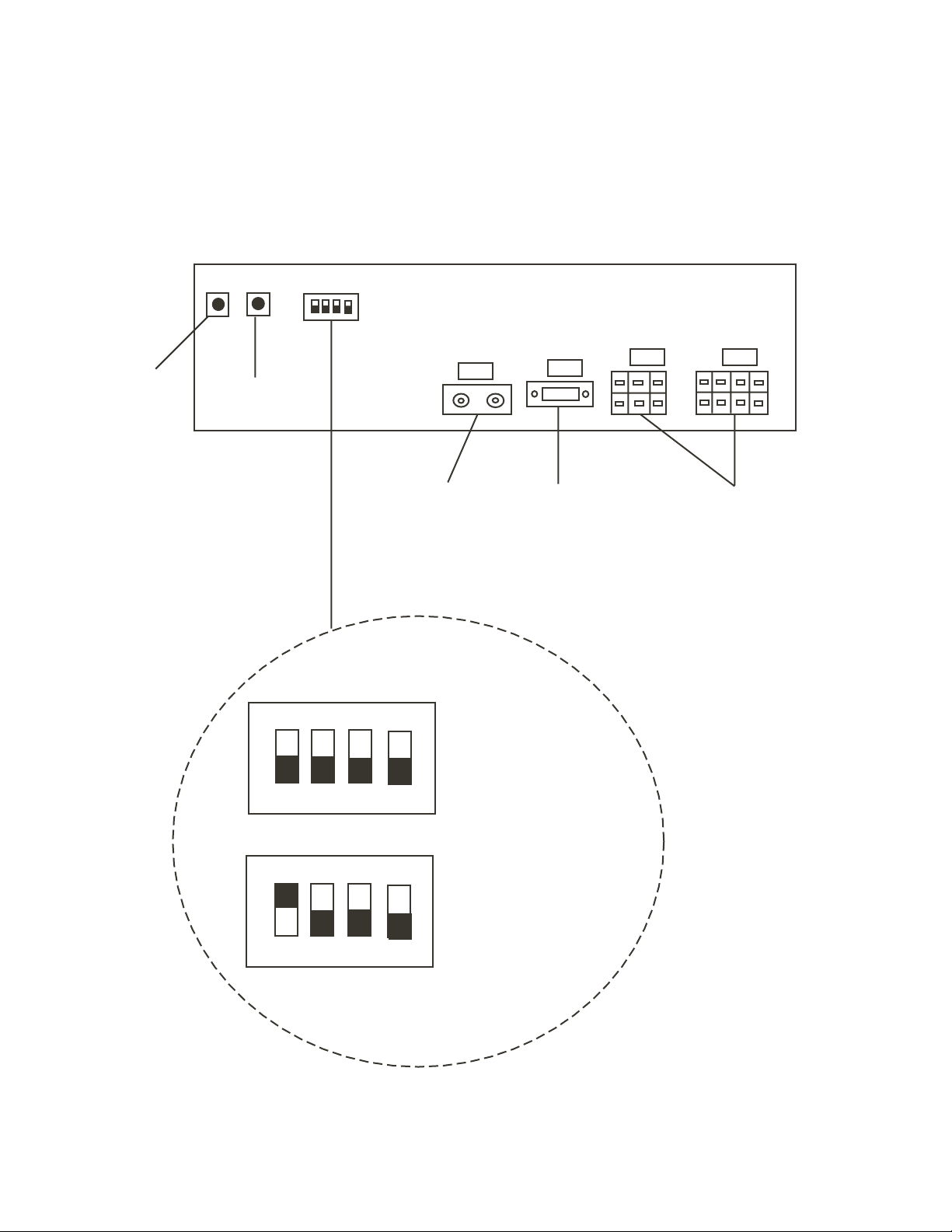
PSW2
Sega Naomi System
Filter Board Information
Connector Description etc.
PSW1
DIPSW1
Service
Switch
Test
Switch
CN4
Preamp Level
Audio Out
1
2
4
Setting for High
Resolution 31KHZ
1 -4 off
CN3
VGA Level
Video Out
CN2 CN1
Power Connectors
www.seuservice.com
1
233
Setting for Standard
Resolution 15KHZ
1 on 2-4 off.
10
Page 13
1. HANDLING PRECAUTIONS
To prevent electric shock or IC Board malfunctioning, be sure to turn
off the power for the cabinet when installing or removing the IC Board.
Extraneous matter such as dust on the IC Board can cause the IC Board
to generate heat and result in a fire due to short circuit, etc. Ensure the
IC Board surfaces are always kept clean.
Use NAOMI for the cabinets compatible with JVS. Using NAOMI for
the cabinet other than those compatible with JVS can cause generation
of heat and a fire.
STOP
IMPORTANT
Be sure to connect the IC Board and connectors completely.
For the IC Board circuit inspection, only the use of Logic Tester is
Do not subject the IC Board to static electricity when installing the IC
When soldering buttons, etc. to the wire harnesses, be sure to remove
Using NAOMI without the Shield Case can cause electric wave trouble.
The monitor frequency corresponding to NAOMI is 15kHz or 31kHz.
Insufficient insertion can damage IC Board, etc.
permitted.
The use of ordinary testers is not permitted as these can damage the IC
Board.
Board in the cabinet or when connecting wire harness connectors to the
IC Board.
the wire harnesses from the IC Board so as not to subject the IC Board
to heat.
Be sure to use NAOMI together with the accessory Shield Case.
NAOMI can not be used for the cabinet incorporating a monitor or
projector not corresponding to 15kHz or 31kHz.
Concerning the display of JAMMA VIDEO STANDARD:
JAMMA VIDEO STANDARD adopted by NAOMI is referred to as JVS. As against this
Standard, the conventional JAMMA STANDARD which employs 56P Edge Connectors adopted
by ST-V, etc. is displayed as Old JAMMA STANDARD.
The specific Manual attached to each game sometimes displays JVS as JV STANDARD, New
JAMMA STANDARD, or JAMMA 2 STANDARD AGAINST OLD JAMMA STANDARD as
JAMMA STANDARD, JS, etc.
The contents herein described are subject to change without notice.
11
www.seuservice.com
Page 14

2. SPECIFICATIONS
1
ON-SCREEN DISPLAY
Monitor Position
CONTROL PANEL
2
Horizontal Synchronous Frequency
HORIZONTAL
15/31 kHz
8WAYS
PLAYER 1 PLAYER 2
LEVER TOP SPIN
SW2
2P
1P
SW1
START SW
LOB SHOT BUTTON
(Press both buttons at once)
BUTTON
(SW1)
8WAYS
SW2
SW1
SLICE SPIN
BUTTON
(SW2)
LEVER: Character movement or shot direction
TOP SPIN BUTTON: Top spin shot (ground stroke or volley automatically
SLICE SPIN BUTTON: Slice spin shot (ground stroke or volley automatically
LOB SHOT BUTTON: Lob shot (Hits a ball highly.)
(Note 1) Top spin is the shot that applied order rotation (vertical rotation) to the ball. A
(Note 2) Slice spin is the shot that applied reverse rotation to the ball. A ball flies late as
(Note 3) Lob is the shot of a high arch that passes over a partner's head.
www.seuservice.com
chosen by CPU)
chosen by CPU)
ball flies quickly and bounds highly; an orbit is high.
it floated and bounds low; an orbit is low.
It's effective when passing the head top of the partner approaching the net.
12
Page 15

Minimum DIMM Memory Capacity
3
256 MB
13
www.seuservice.com
Page 16

GAME SUMMARY
A versus type tennis game featuring the 16 actual professional tennis players.
The type of game played is men's/women's singles and also men's/women's/mixed
doubles.
Max two players can play this game in versus competition singles (SINGLES: VERSUS),
or collaborated doubles (DOUBLES: TEAM PLAY).
HOW TO PLAY
1
Insert a coin(s), and the credit display on the monitor counts up.
When the one credit equivalent coins are inserted, the display changes to "PRESS
START BUTTON" from "INSERT COIN (S)".
Press the START Button while "PRESS START BUTTON" is displayed, and the
2
character selection screen appears. Bring the arrow to the desired character and press Top
Spin Button (SW1) or Slice Spin Button (SW2) to decide the character being selected.
To win the game, you have got to take first the number of games that have been set in the
3
GAME ASSIGNMENT (default setting is 2 games). If you win, you can proceed to the
next stage. There are a total of 5 stages in this game, and wining the game results in
proceeding to the ending screen and game over.
4
When you wish to intrude into a versus game, insert coin(s) and press the START Button
anytime in the game play. If the DOUBLES setting is ON, the select screen of versus
competition singles (SINGLES: VERSUS) or collaborated doubles (DOUBLES: TEAM
PLAY) appears.
GAME SCREEN
1P Rafter
GAME
Player's Name
COM Henman
GAME
Number of games taken
Score
1P 30
COM 40 200km/h
www.seuservice.com
Serve speed
14
Page 17

CHARACTERS AND STAGES
Male pro tennis players:
Patrick Rafter (Australia)
Tim Henman (Germany)
Cedric Pioline (France)
Yevgeny Kafelnikov (Russia)
Female pro tennis players:
Venus Williams (U.S.A.)
Serena Williams (U.S.A.)
Lindsay Davenport (U.S.A.)
Monica Seles (U.S.A.)
Tommy Haas (Germany)
Thomas Enqvist (Sweden)
Magnus Norman (Sweden)
Carlos Moya (Spain)
Mary Pierce (France)
Arantxa Sanchez-Vicario (Spain)
Jelena Dokic (Yugoslavia)
Alexandra Stevenson (U.S.A.)
VENUES
SINGLES: A total of 5 stages (CPU randomly selects stage from 1 to 4, and the final stage is
fixed.)
DOUBLES: A total of 3 stages (CPU randomly selects stage from 1 to 2, and the final stage is
fixed.)
VERSUS COMPETITION (VS): CPU randomly selects stages.
Australia Stage (Hard court)
France Stage (Clay court)
U.S.A. Stage (Hard court)
England Stage (Grass court)
Tokyo Stage (Carpet court/Final stage)
15
www.seuservice.com
Page 18

3. TEST MODE
A. SYSTEM MENU
STOP
When settings are changed in SYSTEM ASSIGNMENTS, COIN
ASSIGNMENTS, and GAME ASSIGNMENTS of GAME TEST MODE,
be sure to exit from the test mode of SYSTEM MENU screen. The contents
IMPORTANT
of setting changes are stored in the IC on the BOARD when exiting from the
Test Mode. If the power is turned off in the Test Mode (before exiting), the
contents of setting changes are ineffective. In this case, the settings remain
unchanged.
This test mode mainly allows the IC Board to be checked for accurate functioning, monitor color
to be adjusted as well as COIN ASSIGNMENTS and GAME ASSIGNMENTS to be adjusted.
1) After turning power on, press the TEST Button to have the following SYSTEM MENU
displayed.
SYSTEM MENU
RAM TEST
JVS TEST
SOUND TEST
C.R.T. TEST
SYSTEM ASSIGNMENTS
COIN ASSIGNMENTS
BOOKKEEPING
BACKUP DATA CLEAR
CLOCK SETTING
DIMM BOARD TEST
GAME TEST MODE
[ X X X X X X X X X ]
-> EXIT
SELECT WITH SERVICE
BUTTON
AND
PRESS TEST BUTTON
123
In the SYSTEM ASSIGNMENTS,
CABINET TYPE is set to 2 PLAYER(S),
MONITOR TYPE is set to HORIZONTAL,
and SERVICE TYPE is set to COMMON.
144424444443
COIN ASSIGNMENTS initial settings as follows:
COIN CHUTE TYPE: COMMON
COIN/CREDTI SETTING: #1
COIN CHUTE #1 (#2): 1 COIN 1 CREDIT
SEQUENCE SETTING of COIN ASSIGNMENTS functions as follows:
SEQUENCE 1: Number of credits required for game start
(initial value = 1 CREDIT).
SEQUENCE 2: Number of credits required for CONTINUE
(initial value = 1 CREDIT)
SEQUENCE 3 ~ 8: NOT USED.
12443
MEANING OF DISPLAY IN BOOKKEEPING 2/2
P1 (P2) SEQ 1: Play frequency of Player 1 (Player 2)
P1 (P2) SEQ 2: Frequency of CONTINUE by Player 1
(Player 2).
P1 (P2) SEQ 3 ~ 8: NOT USED.
2) Press the SERVICE Button to move the arrow. Bring the arrow to the desired item and press
the TEST Button.
3) Press the TEST Button in the GAME TEST MODE to display the GAME TEST MODE
peculiar to this game. See the next page onward.
4) Upon finishing the test, bring the arrow to EXIT and press the TEST Button to return to the
Game mode.
For detailed explanations as regards the SYSTEM TEST MODE, refer to NAOMI SERVICE
MANUAL (420-6620-01).
www.seuservice.com
16
Page 19

B. GAME TEST MODE
Bring the arrow to the GAME TEST MODE in the SYSTEM MENU and press the TEST
Button to display the TEST MENU screen peculiar to Virtua Tennis 2.
<<GAME TEST MODE>>
INPUT TEST
OUTPUT TEST
GAME ASSIGNMENTS
BOOKKEEPING
BACKUP DATA CLEAR
-> EXIT
SELECT WITH SERVICE BUTTON
AND PRESS TEST BUTTON
TEST MENU
• Bring the arrow to the desired item with the SERVICE Button and press the TEST
Button to confirm.
• Bring the arrow to EXIT and press the TEST Button to return to the SYSTEM MENU
screen.
17
www.seuservice.com
Page 20

a. INPUT TEST
This test displays the state of each switch & button. If the display goes ON when the
switch or button is activated, the connection is satisfactory.
<<INPUT TEST>>
PLAYER 1P 2P
UP OFF OFF
DOWN OFF OFF
RIGHT OFF OFF
LEFT OFF OFF
SHOT1 OFF OFF
SHOT2 OFF OFF
START OFF OFF
PRESS TEST BUTTON TO EXIT
UP: Changes to ON when inclining the LEVER towards the monitor.
DOWN: Changes to ON when inclining the LEVER towards you.
RIGHT: Changes to ON when inclining the LEVER towards the right.
LEFT: Changes to ON when inclining the LEVER towards the left.
SHOT 1: Changes to ON when pressing the SHOT1 (TOP SPIN) Button.
SHOT 2: Changes to ON when pressing the SHOT2 (SLICE SPIN) Button.
START: Changes to ON when pressing the START Button.
Press the TEST Button to return to the TEST MENU screen.
LEFT
UP
SHOT2
RIGHT
1P 2P
SHOT1
START
DOWN
LEFT
UP
SHOT2
RIGHT
SHOT1
DOWN
www.seuservice.com
CONTROL PANEL
18
Page 21

b. OUTPUT TEST
In this test, each winner lamp of 1P/2P and 7 SEG display in the Sega versus cabinet's
billboard can be checked.
<<OUTPUT TEST>>
1P SIDE CHECK
2P SIDE CHECK
CLEAR CHECK
-> EXIT
SELECT WITH SERVICE BUTTON
AND PRESS TEST BUTTON
• Bring the arrow to the desired item with the SERVICE Button and press the TEST
Button to have the selected item checked.
• When "1P (2P) SIDE CHECK" is selected, various messages are indicated in the 7
SEG display while the Winner Lamp of 1P/2P is flashing. To stop the test, bring the
arrow to "CLEAR CHECK" and press the TEST Button.
• Bring the arrow to EXIT and press the TEST Button to return to the TEST MENU
screen.
19
www.seuservice.com
Page 22
c. GAME ASSIGNMENTS
In this test mode, setting for the difficulty, the number of games to take first, etc. can be
changed. Select the item with the SERVICE Button and press the TEST Button to change
the setting.
<<GAME ASSIGMENTS>>
DOUBLES [ ON ]
DIFFICULTY [NORMAL]
MATCH COUNT(CPU) [ 2 ]
MATCH COUNT(V S) [ 2 ]
MATCH COUNT(DBL) [ 2 ]
TIE BREAK (V S) [ OFF ]
DEUCE [ ON ]
-> EXIT
SELECT WITH SERVICE BUTTON
AND PRESS TEST BUTTON
DOUBLES: Can be set to play the collaborated doubles game. If it is set
to ON, you can select versus competition singles (SINGLES:
VERSUS) or collaborated doubles (DOUBLES: TEAM
PLAY) when you intruding into the game. When Sega
versus cabinets such as VERSUS CITY etc. are used, it
recommends to be set to OFF.
DIFFICULTY: Game difficulty setting for CPU versus mode. Selects from
EASY, NORMAL, HARD and VERY HARD.
MATCH COUNT (CPU): Sets the number of games to win when playing in 1P
mode against the CPU. Range is from 1 to 6.
MATCH COUNT (VS):Sets the number of games to win when playing in versus
mode against another player. Range is from 1 to 6.
MATCH COUNT (DBL): Sets the number of games to win when playing in
doubles mode. Range is from 1 to 6.
www.seuservice.com
20
Page 23

TIE BREAK (VS): It is the rule which attaches last one game when the difference
of two or more games does not appear within the number of
setting games, one game is added and a score is in a line, last
one game is decided by the tie-break system.
The tie-break system counts numerically (5-6 etc.), and the
player, which gains seven points or more and two points or
more separated, serves as a winner. In addition, two serves at a
time by turns. Although this rule differs from an actual tennis
rule a little, it recommends using it in convention events as a
fairer judgment rule.
DEUCE: Selects from ON, 9TIMES and OFF. If it is set to "9 TIMES",
DEUCE will continue to 9 times, and will be displayed on the
10th time as "40-40", and the next point scored wins the game.
If set to "OFF", even if it becomes the score of 40-40, it will not
be set to DEUCE, the next point scored wins the game.
EXIT: Returns to the TEST MENU screen.
21
www.seuservice.com
Page 24

d. BOOKKEEPING
PLAY DATA (PAGE 1/3)
This mode displays the playtime related data.
<<BOOKKEEPING>> PAGE1/3
PLAY DATA
PLAY TIME **D **H **M **S
AVERAGE TIME **H **M **S
LONGEST TIME **H **M **S
SHORTEST TIME **H **M **S
VS AVERAGE TIME **H **M **S
VS LONGEST TIME **H **M **S
VS SHORTEST TIME **H **M **S
DBL AVERAGE TIME **H **M **S
DBL LONGEST TIME **H **M **S
DBL SHORTEST TIME **H **M **S
PRESS TEST BUTTON TO CONTINUE
PLAY TIME: Displays game playtime.
AVERAGE TIME: Displays the average game time.
LONGEST TIME: Displays the longest game time.
SHORTEST TIME: Displays the shortest game time.
VS AVERAGETIME: Displays the average versus game time.
VS LONGEST TIME: Displays the longest versus game time.
VS SHORTEST TIME: Displays the shortest versus game time.
DBL AVERAGE TIME: Displays the average doubles game time.
DBL LONGEST TIME: Displays the longest doubles game time.
DBL SHORTEST TIME: Displays the shortest doubles game time.
• Press the TEST Button to migrate to the next page (2/3).
www.seuservice.com
22
Page 25

TIME HISTOGRAM (PAGE 2/3)
By-playtime play frequency is displayed.
<<BOOKKEEPING>> PAGE2/3
TIME HISTOGRAM
00M00S - 00M29S ***
00M30S - 00M59S ***
01M00S - 01M29S ***
01M30S - 01M59S ***
02M00S - 02M29S ***
02M30S - 02M59S ***
03M00S - 03M29S ***
03M30S - 03M59S ***
04M00S - 04M29S ***
04M30S - 04M59S ***
05M00S - 05M29S ***
05M30S - 05M59S ***
06M00S - 06M29S ***
06M30S - 06M59S ***
07M00S - 07M29S ***
07M30S - 07M59S ***
08M00S - 08M29S ***
08M30S - 08M59S ***
09M00S - 09M29S ***
09M30S - 09M59S ***
OVER 10M00S ***
PRESS TEST BUTTON TO CONTINUE
• Press the TEST Button to migrate to the next page (3/3).
CHARACTER DATA (PAGE 3/3)
By-character select frequency, and the number of wins/loses in versus mode are displayed.
<<BOOKKEEPING>> PAGE3/3
CHARACTER DATA
SELECT VS WIN VS LOSE
RAFTER (AUS) *** *** ***
HENMAN (GBR) *** *** ***
PIOLINE(FRA) *** *** ***
KAFELNIKOV(RUS) *** *** ***
HAAS(GER) *** *** ***
ENQVIST(SWE) *** *** ***
NORMAN(SWE) *** *** ***
MOYA(ESP) *** *** ***
V WILLIAMS (USA) *** *** ***
S WILLIAMS (USA) *** *** ***
DAVENPORT(USA) *** *** ***
SELES(USA) *** *** ***
PIERCE(FRA) *** *** ***
SANCHEZ(ESP) *** *** ***
DOKIC(YUG) *** *** ***
STEVENSON(USA) *** *** ***
PRESS TEST BUTTON TO EXIT
• Press the TEST Button to return to the TEST MENU screen.
23
www.seuservice.com
Page 26

e. BACKUP DATA CLEAR
This allows the contents of BOOKKEEPING to be cleared.
<<BACKUP DATA CLEAR>>
ALL CLEAR
-> EXIT(CANCEL)
SELECT WITH SERVICE BUTTON
AND PRESS TEST BUTTON
• When clearing, bring the arrow to "ALL CLEAR" with the SERVICE Button and
press the TEST Button. When the data has been cleared, "COMPLETED" is displayed.
• Bring the arrow to "EXIT" and press the TEST Button to return to the TEST MENU.
www.seuservice.com
24
Page 27
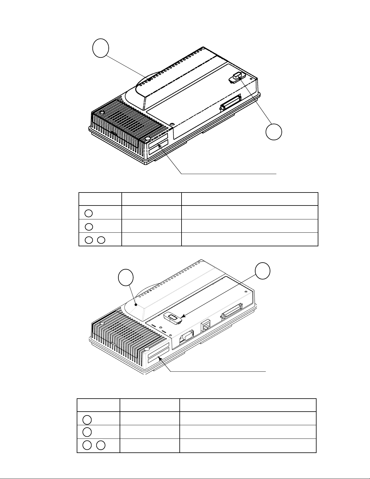
According to your DIMM BD type, attach the correct sticker as follows.
1
442-00084B-01 (STICKER 840-0084B-01)
Attached place
PART NO. DESCRIPTION
2
1 840-0001F ASSY CASE NAO DIMM BD COM
2 KEY CHIP
1 + 2 840-0084B-01 DIMM BD NAO VT2
2
1
442-00084B-02 (STICKER 840-0084B-02)
Attached place
PART NO. DESCRIPTION
1 840-0004F ASSY CASE NAO DIMM BD COM RTOS
2 KEY CHIP
1 + 2 840-0084B-02 RT DIMM BD NAO VT2
25
www.seuservice.com
Page 28
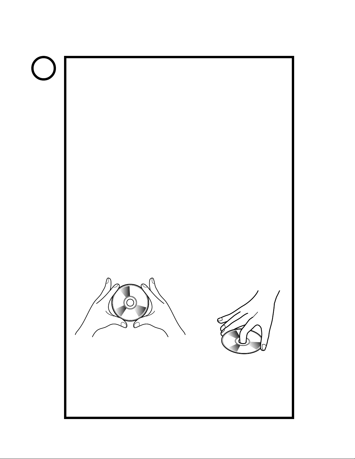
4. SOFT KIT
STOP
Handling the GD-ROM Disc
Do not contaminate the discs with your
IMPORTANT
When cleaning the discs, do not use volatile
Do not use cracked, warped, or damaged discs.
When cleaning a heavily contaminated disc, use clean cloth that has
When holding a disc, be careful not to contaminate it with your
fingerprints or dust particles. Contaminated
discs may lower audio and video quality.
chemicals (benzine, thinner, etc.), cleaning
sprays, and antistatic agents.
Use clean cloth to wipe
Do not attach papers or seals onto the discs; do
not scratch the discs.
the disc gently and into a
radial direction.
Do not use the discs with a sign of peeled seals,
tapes, etc.
Observing these instructions, do not insert such a non-usable disc into
the GD-ROM drive. Otherwise the inserted disc can not be ejected.
been soaked in water and squeezed. Then remove moisture with dry
cloth.
fingerprints.
How to Hold a Disc
With both hands:
Put your thumbs and forefingers of both
hands on the disc's 4 circumference tips.
With one hand:
Insert your forefinger into a central
hole and at the same time put your
thumb and middle finger on the
disc's 2 circumference tips.
How to Handle the Key Chip
The key chip is a precision device. Handle it carefully because it may be
damaged by heat, shock, and static electricity.
Use the key chip with the GD-ROM disc of the corresponding game that
has been shipped together with the key chip.
www.seuservice.com
26
Page 29

4
2
3
1
When you order the GD-ROM disc only, please mention the Part No. 610-0625-
PART NO. DESCRIPTION
1 + 2 + 3 + 4 610-0630-0015 GD SOFT KIT VT2 ENG
1 NAOMI GDROM VT2
2 KEY CHIP
3 420-6621-0015E SERVICE MANUAL VT2 ENG
4 253-5507 DISC CASE WITH IC HOLDER
1 + 4 610-0625-0015 GD SOFT VT2
****
.
27
www.seuservice.com
Page 30

5. GAME BOARD
Do not expose the Game Board so as to avoid causing an accident or
malfunctioning.
Static electricity discharge can damage electronic parts on the IC Board.
Before starting work by opening the Shield Case Lid, be sure to touch
grounded metallic surfaces to discharge physically charged static electricity.
When replacing the Game Board, refer to the CVT Manual and Instruction
Manual.
PART NO. DESCRIPTION
ASSY CASE ( 1 + 2 ) 840-0084D-01 ASSY CASE NAO VT2 USA :USA
840-0084D-02 ASSY CASE NAO VT2 EXP :OTHERS
840-0084D-03 ASSY CASE NAO VT2 KOR :KOREA
840-0084D-04 ASSY CASE NAO VT2 AUS :AUSTRALIA
1 ASSY CASE NAOMI 840-0001A-01 ASSY CASE NAOMI MAIN BD USA :USA
MAIN BOARD 840-0001A-02 ASSY CASE NAOMI MAIN BD EXP :OTHERS
840-0001A-03 ASSY CASE NAOMI MAIN BD KOR :KOREA
840-0001A-04 ASSY CASE NAOMI MAIN BD AUS :AUSTRALIA
2 ROM CASE 840-0084C ROM CASE NAO VT2
www.seuservice.com
28
Page 31

600-7155
Phono
plugs
2
9
72
91
71
SPEAKER OUTPUTS
NAOMI KIT UNIVERSAL
WIRING DIAGRAM (1/1)
838-13616
AUDIO POWER AMP 2CH
JST VH 4P
0V
17V
0V
17V
TRANSFORMER
560-5407
0V
120V
WHITE(U/P)
51
41
50
50
31
P C
3
5k pot
2
50
50
10
30
1
34256
1
[GD ROM DRIVE]
50
50
10
30
[Extra]
MUST BE SET TO "IN"
TO USE INPUTS ON CN3
OUT IN
JP1
1 VCC
2 VCC
3 NC
4 1P SW6
5 1P SW7
6 1P SW8
7 NC
CN3
8 2P SW6
9 2P SW7
10 2P SW8
11 NC
12 NC
13 GND
14 GND
To Extra
Yellow Wire
30 10 50
30 10 50
1
CN6
6
600-6743-050
600-7141-050
838-13683-91
To PIN 8
of Jamma
80
50
132
P C
120 Vac Input
COIN COUNTER
JST VL
GND
GND
+5V
+3.3V
P C
JST VL
GND
GND
GND
+12V
400-5397
+5V
+3.3V
P C
SW REGU FOR JVS
29
JAMMA CONNECTIONS USED ARE:
° VIDEO OUT
° SWITCH INPUTS
° SWITCH GROUND RETURNS
° COIN COUNTER OUTPUT
NOTE: THERE ARE TO BE NO
CONNECTIONS MADE TO THE
JAMMA INTERFACE OTHER THAN
THE ABOVE FOREMENTIONED.
CDE
607080AB
1020304050
www.seuservice.com
Page 32

Warranty
Your new Sega Product is covered for a period of 90 days from the date of shipment. This certifies
that the Printed Circuit Boards, Power Supplies and Monitor are to be free of defects in workmanship or materials under normal operating conditions. This also certifies that all Interactive Control
Assemblies are to be free from defects in workmanship and materials under normal operating conditions. No other product in this machine is hereby covered.
Sellers sole liability in the event a warranted part described above fails shall be, at its option, to
replace or repair the defective part during the warranty period. For Warranty claims, contact your
Sega Distributor.
Should the Seller determine, by inspection that the product was caused by Accident, Misuse, Neglect, Alteration, Improper Repair, Installation or Testing, the warranty offered will be null and void.
Under no circumstances is the Seller responsible for any loss of profits, loss of use, or other damages.
This shall be the exclusive written Warranty of the original purchaser expressed in lieu of all other
warranties expressed or implied. Under no circumstance shall it extend beyond the period of time
listed above.
Page 33

 Loading...