

Page 1
A
www.securitron.com | techsupport@securitron.com
© 2015, Hanchett Entry Systems, Inc., an ASSA ABLOY Group company.
C
B
C
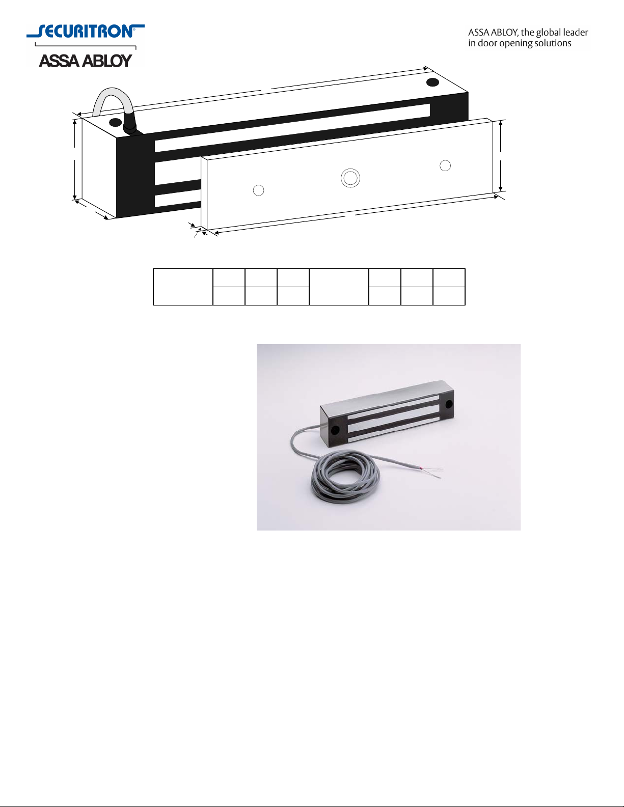
MODEL 32
MAGNET
A
8B1.5C1.88
MODEL 32
A
STRIKE
A
6.25B1.63C.5
B
ELECTROMAGNETIC LOCK – Model 32
Features
• 600 pounds of pull-apart holding
force
• Lifetime replacement warranty
• Power consumption of 300mA @
12VDC & 150mA @ 24VDC
• Availabl
• Instant release circuit, no
residual magnetism
• Surface mounts using only a drill
and allen wrench
• Fully sealed electronics, tamper
proof & weather proof
• Mounted using steel machine
screws into blind finishing nuts
• Architectural brushed stainless
steel finish
• Polished brass, clear anodized, & polished stainless finish dress covers available
• Hardware accessories include brackets, housings, and dress covers as needed for every
opening type
• Ten feet of jacketed stranded conductor
• Lock and strikes plated to provide corrosion resistance
• Fail Safe
• UL listed
e in 12 VDC or 24 VDC
Options
• Bondstat Form ‘C’ – Instantaneous lock status sensing without the use of auxiliary
switches or reed relays
• DPS Door Status – Integrated door reed switch w/ built in resettable polyswitch
• Face Mount – Mounting holes on the face of the lock for mounting on inswing doors and
gates
Page 2
ELECTROMAGNETIC LOCK – Model 32 (cont’d)
www.securitron.com | techsupport@securitron.com
Operating Temperature
-40 to 60C [-40 to 140F]
How to Order
Part Numbe
M32 Maglock Model 32, 12VDC, 24VDC
M32F Maglock Model 32, 12VDC, 24VDC, Face Mount
M32B Maglock Model 32, 12VDC, 24VDC, Bondstat
M32D Maglock Model 32, 12VDC, 24VDC, Door Position
M32FD Maglock Model 32, 12VDC, 24VDC, Face Mount, Door Position
M32FB Maglock Model 32, 12VDC, 24VDC, Bondstat, Face Mount
M32BD Maglock Model 32, 12VDC, 24VDC, Bondstat, Door Position
M32FBD Maglock Model 32, 12VDC, 24VDC, Face Mount, Bondstat Door Position
ARCHITECTURAL SPECIFICATION – Electrom
Product Description
r
agnetic Lock
Model 32
2.x MAGNETIC LOCKS
A. All electromagnetic locks shall be manufactured by Securitron Magnalock Corp.,
Sparks, NV, an ISO 900
B. Locks shall be capable of providing a pull-apart or tensile holding force of at least
600 pounds. A laboratory test certifying the minimum holding force shall be
submitted by the manufacturer upon request.
C. Electromagnetic locks shall have a lifetime replacement warranty.
D. Locks shall not consume more than three and one-half (3.5W) watts of power
(300mA @ 12VDC) and (150mA @ 24VDC).
E. Locks shall not exceed 21 cubic inches (8 inches x 1.75 inches x 1.5 inches) in size.
F. Locks shall be fully sealed in resin to provide tamper and weather proofing.
G. Mount locks using two .25 inch x 2.25 inch machine screws into blind finishing nuts
with steel threads that extend through the entire body of the lock.
H. Mount strike plates to provide a "floating" movement to assure automatic self-
alignment with the lock.
I. Finish is architectural brushed stainless steel, other finishes available by selecting
optional dress covers.
J. Hardware accessories shall include brackets, housings, and dress covers.
K. Ten feet of jacketed stranded conductor shall be provided for electrical connection.
L. Anti-tamper caps shall be provided for any exposed holes.
M. The locks and strikes shall be plated to provide corrosion resistance.
1 certified manufacturer.
 Loading...