

Page 1
Securitron Magnalock Corp. www.securitron.com ASSA ABLOY, the global leader
Tel 800.624.5625 techsupport@securitron.com
in door opening solutions
DK-38 Installation & Operating Instructions
Introduction
The DK-38 Digital Keypads by Securitron offer Wiegand output for universal compatibility with
access control systems or the DKC Digital Keypad Controller by Securitron. The 3x4 illuminated
keypad features a flush-mount stainless steel faceplate.
DK-38 keypads are shipped in ‘Wiegand mode’ from the factory. When interfacing with
the DKC, please change the keypad to ‘Character mode’ and ensure that ‘Character’ is
selected in the DKC Programming Tool. The advanced programming features available
in Character mode allow a user to customize the operation of the DKC to fit the specific
needs of their installation. Instructions on how to change from Wiegand to Character
mode are found in the Changing to Character Mode section below.
Box Contents
Keypad with mounting hardware pack
Installation & Operating Instructions
Surface Mount Wall Box
Flush Mount Wall Box
16’ of wire
Specifications
Power Selection
12V or 24V DC @ 100mA max
Environmental
Operating temperature: -10° to 140°F (-23° to 60°C)
Storage temperature: -10° to 150°F (-23° to 65°C)
Humidity: 0% to 95% relative humidity
Installation
The DK-38 can be installed using one of two wall boxes; a surface mount wall box or a flush
mount wall box. Note that the DK-38 can be used outdoors with the optional rain cover
(Securitron part number WCC) which will allow the DK-38 to be mounted in outdoor locations
not directly exposed to rain or snow. Additionally, when used outdoors a weatherproof gasketed
wall box is recommended (Securitron part number WBB).
Note that the surface mount wall box must be used for the tamper feature of the DK-38 to
operate properly. Once the DK-38 is wired per the wiring diagram in the Wiring section of this
document, gently install the spring onto the push button switch with the tapered side of the
spring facing downwards towards the PCB. The spring will allow the tamper feature to operate
with the surface mount wall box.
© Copyright, 2013, all rights reserved PN# 500-20760
Page 1 Rev. A, 06/13
Page 2
Surface Mount Wall Box
4 5 6 7 8 9
L
Separate the wall box cover and base.
Remove the rectangular knockout in the center of the base only if the tamper switch will
not be used.
Drill an opening in the wall through which the wires will be routed.
o If using the tamper switch, drill a hole for the wires ensuring the hole will not
interfere with the operation of the push button tamper switch.
Mount the base onto the wall over the wire opening using the supplied metal screws and
plastic anchors.
Mount the DK-38 to the cover using tamper resistant #6 screws (recommended) or #6
conventional screws. Program the unit prior to securing in place.
Pull wires through the wall/center of the base and connect to the DK-38 wiring terminals
per instructions in the Wiring section of this document.
Push the wall box cover onto the base until it snaps into place.
Flush Mount Wall Box
Cut out an opening in the wall into which the box will be mounted.
Route wiring through one of the four knockouts in the back of the box.
Push the box into the wall and secure in place using the two swing clamps.
Connect wires to the DK-38 wiring terminals per instructions in the Wiring section below.
Program the unit prior to securing in place.
Mount the DK-38 to the box using tamper resistant #6 screws (recommended) or #6
conventional screws.
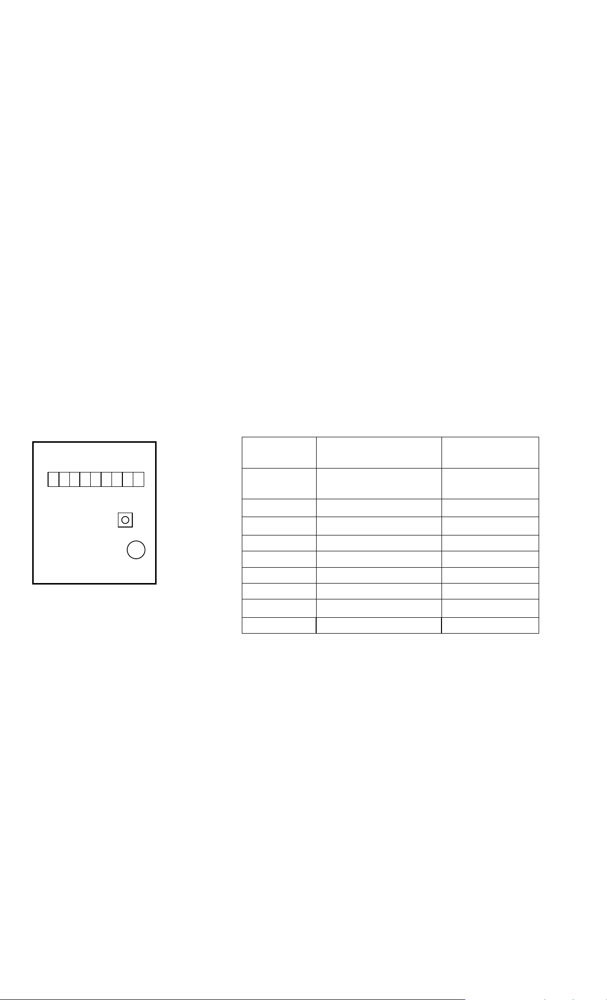
DK-38 Wiring Wiring Terminal Connections
DC+
D0
D1
3
2 1
YE
RED
GRN
Wiring Terminals
Tamper Switch
Beeper
BUZ
TAMP
GND
DK-38
Terminal
DC+
D0 Wiegand data zero Green
D1 Wiegand data one White
GRN Green light Orange
DK-38 Wiring
Reference
Positive DC supply
lead
Suggested
Wire Color
Red
RED Red light Brown
YEL Yellow light Blue
Each terminal is provided
with a marking
for easy reference.
BUZ Audible buzzer Yellow
TAMP Tamper indicator Purple
GND Ground Black
Note that suggested wire color for ‘YEL’ terminal is
BLUE and suggested wire color for ‘BUZ’ terminal is
YELLOW
Feedback and Entry Overview
The DK-38 comes with LED indicator lights above the keypad; green, yellow, and red. These
three indicator lights and the backlight provide feedback during operation. When the DK-38 is in
Wiegand mode there is no yellow feedback light when connected to an access controller. The
yellow light is designed to work with the Securitron DKC Digital Keypad Controller. The three
indicator lights are intended for operation through an access controller either through a drycontact connection to ground or an open-collector driver. Please refer to the access controller for
information about the meaning of the indicator lights. The table below is only for use with
Securitron DKC controller.
PN# 500-20760
Page 2 Rev. A, 06/13
Page 3

INDICATOR ACTION MEANING
While in programming mode an error was made during
Red Light Single Flash
program entry; or
A 5 second timeout occurred at any time during a
programming step.
While in programming mode a confirmation that a valid
Red Light Double Flash
program entry was made; or
During normal operation the DK-38 was put into or
taken out of lockout mode.
Red Light
Red Light
Yellow Light
Yellow Light
Continuously
On
Continuously
On
Continuous
Flashing
Continuously
On
During normal operation the relay is energized while the
DK-38 is in relay timer mode.
While in normal operation the DK-38 is in passage
mode; or
The DK-38 is in toggle mode and the relay is energized.
While in programming mode the light will flash once per
second.
While in normal operation this indicates that there are
no codes in memory.
Green Light Single Flash Key press detected.
Green Light
Continuously
On
Backlight Double Flash
While in normal mode a 30-second lockout occurred
after 16 wrong digits were entered; light turns off after
lockout time.
While in normal mode a valid code was entered while
the DK-38 was in lockout mode.
Note the table above is for use with Securitron DKC controller.
The DK-38 is provided with a beeper that can be used to indicate when a button is pressed or
the relay is energized. The beeper functions are detailed in the table below and are valid for use
with the Securitron DKC Controller. Note that when shipped from the factory there is a paper
label applied to the top of the beeper. This label decreases the volume of the beeper. If more
volume is needed simply remove the label from the beeper to obtain maximum volume.
INDICATOR MEANING
Single short
beep
A button press; or
Entry into Programming Mode
While in normal operation:
Single long
beep
User ID entered is greater than 65535 no transmission occurred; or,
Six digits were entered; no transmission occurred
While in Programming Mode:
An error or non-acceptance of a new facility code has occurred
While in Programming Mode:
Double beep
Acceptance of a new facility code in Wiegand Mode
Changing from Wiegand to Character Mode
When entering a sequence the DK-38 has a 5 second timeout that will erase the internal buffer
when a key is not pressed within 5 seconds. For example, if the correct code is 2-2-6-7 and the
user enters 2-2-6 followed by a 5 second delay and then enters 7 the DK-38 will not operate.
PN# 500-20760
Page 3 Rev. A, 06/13
Page 4

Keypad Operation
DK-38 keypads are shipped from the factory in ‘Wiegand mode’ of operation. To change the
facility code or mode of operation, follow the steps below:
Entering into Programming Mode
1. Remove power from the keypad.
2. At the keypad, temporarily connect the ‘YEL’ terminal to the ‘GND’ terminal.
3. Apply power to the keypad and the yellow light will be on.
4. Without touching the keypad wait 5 seconds and the keypad will produce a single short beep
to indicate that programming mode has been entered.
Change to Wiegand mode and set facility code
1. Enter into programming mode (see above).
2. Within 30 seconds, enter a valid facility code of 1 to 3 digits in length. The code cannot be
greater than 255. If more than 3 digits are entered programming mode will automatically
terminate with an error.
3. Press the ‘*’ key and the DK-38 will beep twice. Programming mode will automatically exit.
4. Remove the temporary wire connecting the ‘YEL’ terminal to the ‘GND’ terminal.
5. Remove power from the keypad for 10 seconds.
Changing to Character Mode
1. Enter into programming mode (see above).
2. Within 30 seconds press the ‘#’ key and the DK-38 will beep twice. Programming mode will
automatically exit.
3. Remove the temporary wire connecting the ‘YEL’ terminal to the ‘GND’ terminal.
4. Remove power from the keypad for 10 seconds.
In Character Mode a valid user ID must be 1 to 5 digits in length and the ID cannot be greater
than 65535. If more than 5 digits are entered or if the ID entered is greater than 65535 an
audible error will sound, the buffer will be cleared, and no transmission will be sent. A valid user
code must be followed by pressing the ‘’ key.
Technical Support
For general questions concerning this or other Securitron products please visit the Securitron
website www.Securitron.com or contact Securitron Technical Support at (800) 624-5625 or
email TechSupport@assaabloyems.com.
For MAGNACARE
Lifetime Replacement Warranty information please visit:
www.Securitron.com/en/site/securitron/About/MagnaCare-Warranty/
PN# 500-20760
Page 4 Rev. A, 06/13
 Loading...