

Securitron DK-26W Installation & Operating Instructions Manual
© Copyright, 2004, all rights reserved • Securitron Magnalock Corp., 550 Vista Blvd., Sparks NV 89434, USA
Tel: (775) 355-5625 • (800) MAGLOCK • Fax: (775) 355-5636 • Website: www.securitron.com
An ASSA ABLOY Group company
PN# 500-12500 Page 1
Rev. A.2, 1/04
SECURITRON MODEL DK-26W DIGITAL KEYPAD
INSTALLATION & OPERATING INSTRUCTIONS
1. DESCRIPTION
Securitron's DK-26W is a two piece digital keypad system designed to output Weigand 2601
format data and therefore integrate into an access control system just as if it was a card reader.
It consists of two components: the keypad and the CPU board connected by a 16 ft. cable. The
rugged stainless steel keypad may be mounted outdoors in any environment as it is fully
weatherproof. The keypad features two active LED’s (green and red controlled by the system)
and a beeper.
2. PHYSICAL INSTALLATION
The first step is to plan the physical location of the two components. The keypad is normally
surface mounted on the outside of the door to be controlled, and the CPU Board is mounted
inside the protected area safe from tampering.
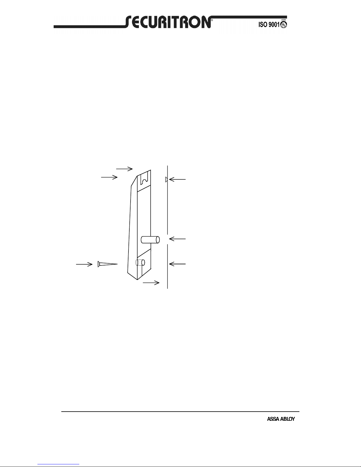
FIG. 1: PHYSICAL INSTALLATION OF KEYPAD
MOUNTING
SURFACE
(1) MOUNT SCREW TO ENGAGE SLOT AT
TOP OF KEYPAD
DRILL 1/8" (3MM) HOLE
(2) DRILL 3/8" (10MM ) HOLE FOR CABLE
(3) SECURE BOTTOM WITH SECOND
SCREW. COVER SCREW HEAD WITH
"DK-26" LABEL.
DRILL 1/8" (3MM) HOLE
NOTE: CHOOSE PHILIPS OR SPANNER
(TAMPER) HEAD SCREW
CABLE
To install the keypad, holes must be drilled for the 2 mounting screws and the cable. A template
is not provided due to unavoidable variations on the cable exit of each keypad. Referring to
Figure 1, note that the top screw engages the slot at the top of the keypad. Once the top screw
has been installed, the location of the cable hole should be set roughly by positioning the
keypad and marking the cable hole point. Make sure the keypad is pulled down firmly on to the
screw. A 3/8" (10MM) hole is then drilled for the cable. After the cable has been pulled through,
the final screw secures the keypad to the wall. Note that 2 alternate bottom screws are supplied
with the unit. One is a #10 spanner head for improved tamper resistance. Alternately the #8
Phillips standard screw may be used. After this, peel the backing of the enclosed Securitron
DK-26 label and affix it to the bottom of the keypad covering the head of the screw. This
not only improves the appearance of the keypad but helps foil casual vandalism. Note finally
that a blank rectangular label has also been furnished. This can be used to cover up the
“BELL” legend if desired.
The CPU Board is furnished in a snap-apart steel enclosure with the board itself mounted on
plastic snap-trak. The CPU Board must be installed in a dry location free of extremes of
temperature and humidity. If the 16 ft., twelve conductor cable that is included is not of sufficient
length, additional cabling can be spliced by the installer. However, a long cable run can give
Rev. A.2, 1/04 Page- 2
rise to electronic noise problems in certain environments. It should therefore be avoided where
possible and in no case should cable length exceed 30 ft. (10 meters).
Cable entry to the CPU board enclosure can be handled in one of two ways. There is a hole in
the bottom of the enclosure, the use of which creates the most attractive installation as the cable
is completely hidden. Alternately, there is a side knockout in the enclosure cover which permits
surface mounting of the cable. The side knockout also permits a wiring technique which is
convenient when the CPU board enclosure is to be mounted in an awkward location such
as above a drop ceiling. You can pop the board itself out of its snap track and make all your
connections with the board in your hands. The board is then re-snapped into the plastic trak.
The enclosure cover snaps on with the wires emerging from the side knockout. If you use this
technique, avoid touching the components or rear pins on the board as much as possible.
Static electricity can destroy the processor. Also when you snap the board back in its track,
make sure it’s securely done. Sometimes you need to squeeze the outer lips of the track to
insure that the board edges are really seated in the slot.
3. WIRING
3.1 POWER, DATA AND KEYPAD WIRING
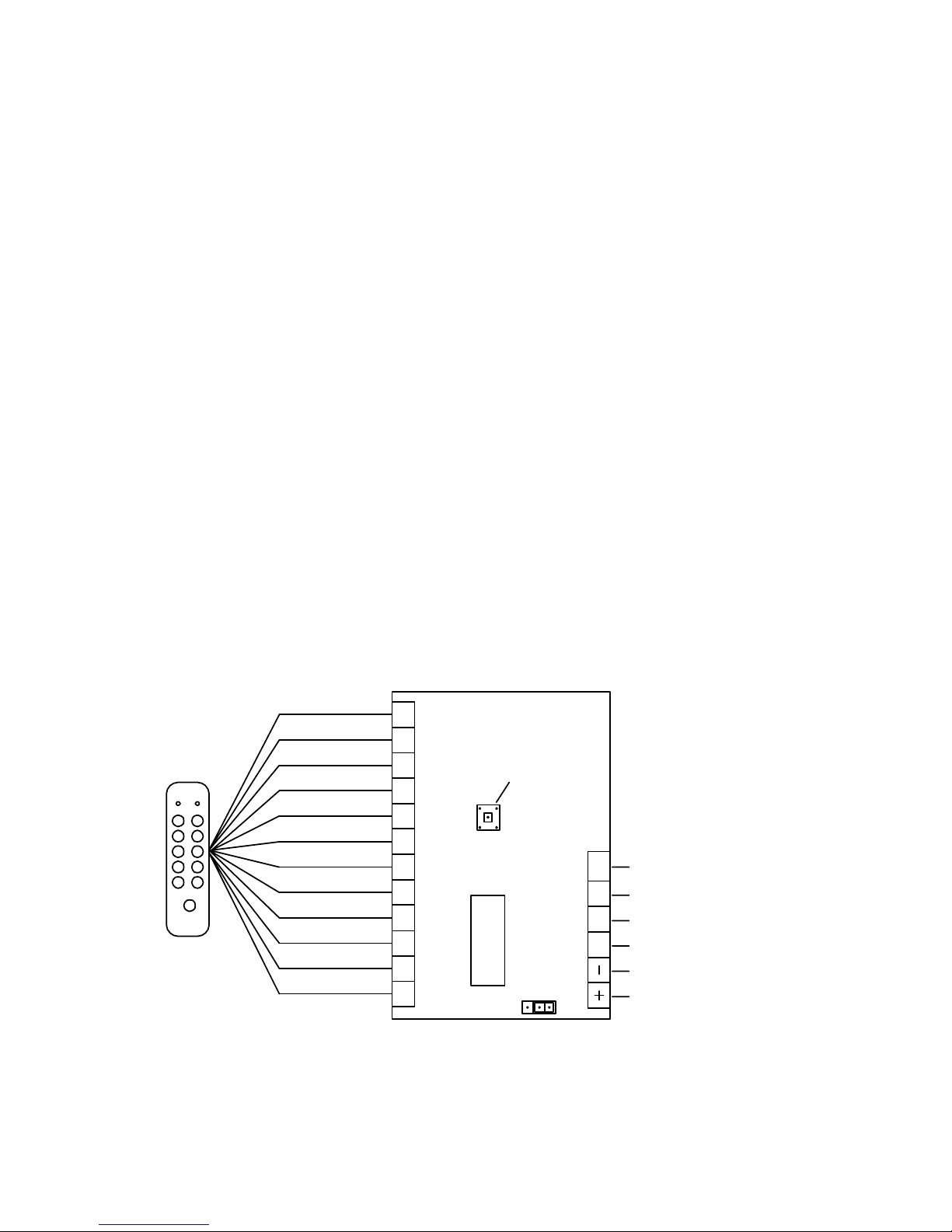
Figure 2 shows the DK-26W CPU Board. You will make connections to the 18 terminals as
shown in the drawing and either leave the jumper block in the factory set position (connects pins
2 and 3) if you plan to power the DK-26W with 12 VDC or move the jumper to connect pins 1
and 2 if you will be using 5 VDC. Note that operation at 12 volts with the jumper block in the 5
volt position can damage the unit.
Note that the DK-26W will not operate on AC power. It will, however, accept full wave
rectified DC power (transformer + bridge rectifier) when it is being powered by 12 VDC.
When it is being powered by 5 VDC, the voltage must be regulated (+/- 1/2 volt). Be sure to
observe polarity when you power the DK-26W.
There are 12 color coded wires in the keypad cable. Refer to Figure 2 and connect each wire to
the indicated terminal on the CPU Board. No other connections may be made to these
terminals (except if two keypads are used with one CPU board).
The DK-26W will draw a maximum of 30 mA at 5 VDC or 12 VDC.
The Weigand output terminals: Data 0 and Data 1 connect to the appropriate inputs of the
access control system. The wire run maximum distance for reliable operation depends on the
wire gauge. A guide line is 200 ft. for 22 gauge; 300 ft. for 20 gauge and 500 ft. for 18 gauge.
FIG. 2: OVERVIEW OF CPU BOARD
GRN YEL RED
BLU
WHT
BLK
GRY
BRN
BGE
ORG PNK VIO
D0 D1 LED XMIT
GREEN
YELLOW
RED
BLUE
WHITE
BLACK
GRAY
BROWN
BEIGE
ORANGE
PINK
VIOLET
MICRO-
PROCESSOR
FACILITY CODE
PROGRAM
BUTTON
TRANSMIT DATA
LED (FROM SYSTEM)
DATA 1
0 VDC (NEG)
+5 OR +12 VDC
DATA 0
132
JUMPER TO SET
VOLTAGE
FACTORY SET 2/3 = 12 V
CHANGE TO 1/2 FOR 5 V
 Loading...