

Securitron DK-26BK, DK-26PBK, DK-26PSS, DK-26SS User Manual
ASSA ABLOY, the global leader
in door opening solutions
MODEL DK-26 DIGITAL KEYPAD SYSTEM
INSTALLATION AND OPERATING INSTRUCTIONS
Securitron Magnalock Corp. www.securitron.com
Tel 800.624.5625 techsupport@securitron.com
© Copyright, 2011, all rights reserved PN# 500-16900
Rev. D, 12/11

Securitron Magnalock Corp. www.securitron.com ASSA ABLOY, the global leader
Tel 800.624.5625 techsupport@securitron.com
in door opening solutions
SECURITRON MODEL DK-26 DIGITAL KEYPAD
TABLE OF CONTENTS AND GUIDE TO THIS MANUAL
SECTION 1. DESCRIPTION -------------------------------------------------------------Page 2
SECTION 2. PHYSICAL INSTALLATION ----------------------------------------------Page 2
SECTION 3. WIRING --------------------------------------------------------------------Page 2
SECTION 3.1 POWER SELECTION -----------------------------------------------------Page 2
SECTION 3.2 CONNECTING THE KEYPAD CABLE TO THE CPU BOARD ----------Page 3
SECTION 3.3 POWER AND ELECTRIC LOCK WIRING-------------------------------Page 3
SECTION 3.3.1 AC LOCK WITH AC POWER ------------------------------------------Page 3
SECTION 3.3.2 DC LOCK WITH AC POWER ------------------------------------------Page 4
SECTION 3.3.3 DC LOCK WITH DC POWER ------------------------------------------Page 5
SECTION 3.4 USE OF THE “F” TERMINAL --------------------------------------------Page 6
SECTION 3.5 ADDING OTHER LOCK CONTROL SWITCHES------------------------Page 6
SECTION 3.6 THE REX FUNCTION-----------------------------------------------------Page 6
SECTION 4. PROGRAMMING -----------------------------------------------------------Page 8
SECTION 4.1 FIXED PROGRAMMING -------------------------------------------------Page 8
SECTION 4.2 KEYPAD CHANGEABLE PROGRAMMING------------------------------Page 9
SECTION 4.2.1 CHANGING THE USER AND PROG. CODE FROM KEYPAD -------Page 10
SECTION 4.2.2. ADDING MULTIPLE USER CODES ----------------------------------Page 10
SECTION 4.3 “MASTERKEY” USE OF THE HARD CODE -----------------------------Page 11
SECTION 4.4 SUBSET CODES ----------------------------------------------------------Page 11
SECTION 4.5 DELETING CODES -------------------------------------------------------Page 11
SECTION 4.6 SETTING THE TIME RANGE AND TOGGLE MODE -------------------Page 12
SECTION 5. CHANGING LED AND BEEPER OPERATION ---------------------------Page 12
SECTION 6 USE OF THE PROGRAMMABLE RELAY ----------------------------------Page 13
SECTION 6.1 DOORBELL FUNCTION --------------------------------------------------Page 13
SECTION 6.2 DURESS FUNCTION -----------------------------------------------------Page 13
SECTION 6.3 ANTI-TAMPER ALARM FUNCTION ------------------------------------Page 13
SECTION 6.4 DOOR PROP ALARM FUNCTION ---------------------------------------Page 14
SECTION 6.5 NIGHTLIGHT FUNCTION -----------------------------------------------Page 14
SECTION 7 ADDITIONAL HARD WIRED OPTIONS----------------------------------Page 14
SECTION 7.1 DUAL PAD OPERATION-------------------------------------------------Page 14
SECTION 7.2. HARD WIRED CODE DISABLING -------------------------------------Page 15
SECTION 7.3 ALARM SYSTEM SHUNTING--------------------------------------------Page 15
SECTION 7.4 ANTI-TAILGATING ------------------------------------------------------Page 16
SECTION 7.5 WIRING WITH TOUCH SENSE BAR AND MAGNALOCK
------------Page 16
APPENDIX A COMMAND SUMMARY----------------------------------------------------Page 17
APPENDIX B TROUBLE SHOOTING ----------------------------------------------------Page 17
MAGNACARE WARRANTY -----------------------------------------------Page 21
© Copyright, 2011, all rights reserved PN# 500-16900
Page 1 Rev. D, 12/11
SECURITRON MODEL DK-26 DIGITAL KEYPAD
INSTALLATION & OPERATING INSTRUCTIONS
1. DESCRIPTION
Securitron's DK-26 is a digital keypad system designed for medium/high security control of
electric locks. It consists of two components: the keypad and the CPU board conn ected by a 16
ft. cable. This allows the CPU board to be mounted within the protected area for higher
security. Tampering with or even destroying the keypad will not release the door. The rugged
stainless steel keypad may be mounted outdoors in any environment as it is fully weatherproof.
The keypad features true 10 digit operation (keys are not paired), three LED’s and a beeper.
2. PHYSICAL INSTALLATION
The keypad is normally surface mounted on the outside of the door to be controlled, and the
CPU Board is mounted inside the protected area safe from tampering.
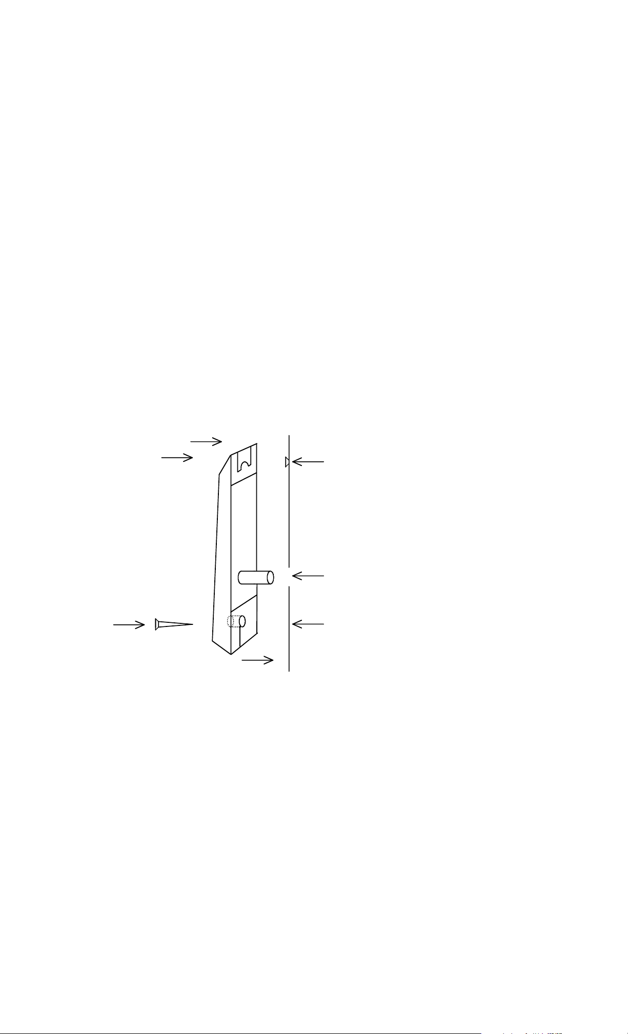
To install the keypad, holes must be drilled for the 2 mounting screw s and the cable. A template
is not provided due to unavoidable variations on the cable exit of each keypad. Referring to
Figure 1, note that the top screw engages the slot at the top of the keypad. Once the top screw
has been installed, the location of the cable hole should be set roughly by positioning the keyp ad
and marking the cable hole point. Make sure the keypad is pulled down firmly on to the screw.
A 3/8" (10MM) hole is then drilled for the cable. After the cable has been pulle d through, the
final screw secures the keypad to the wall. Note final ly tha t a blank rectangular label has also
been furnished. This can be used to cover up the “BELL” legend if you don’t intend to utilize the
doorbell function.
FIG. 1: PHYSICAL INSTALLATION OF KEYPAD
(1) MOUNT SCREW TO ENGAGE SLOT AT
TOP OF KEYPAD
DRILL 1/8" (3MM) HOLE
MOUNTING
SURFACE
CABLE
(2) DRILL 3/8" (10MM) HOLE FOR CABLE
(3) SECURE BOTTOM WITH SECOND
SCREW. COVER SCREW HEAD WITH
"DK-26" LABEL.
DRILL 1/ 8 " (3 MM ) HOLE
NOTE: CHOOSE PHILIPS OR SPANNER
(TAMPER) HEAD SCREW
The CPU Board must be installed in a dry location free of extremes of temperature and humidity.
If the 16 ft., twelve conductor cable that is included is not of sufficient length, additional cabling
can be spliced by the installer. However, a long cable run can give rise to electronic noise
problems in certain environments. It should therefore be avoided where possible and in no case
should cable length exceed 100 ft. (30 meters).
3. WIRING
3.1 POWER SELECTION
The DK-26 operates on 12 to 24 volts AC or DC. Nearly all electric locks operate on voltage
within this range, so the power supply you would normally utilize to operate the electric lock will
also operate the DK-26. Power consumption of the DK-26 depends on voltage and is shown on
the following chart:
DK-26 POWER CONSUMPTION: 12 VOLTS 24 VOLTS
RELAYS, LED’S, + BEEPER ON (MAX) 160 mA 190 mA
PN# 500-16900
Page 2 Rev. D, 12/11
Be sure that your power source is of adequate capacity to operate both the lock and
DK-26. If the installation is "under-powered", the voltage of the supply will drop
rapidly when the lock is energized and this can crash the microprocessor.
3.2 CONNECTING THE KEYPAD CABLE TO THE CPU BOARD
There are 12 color coded wires in the keypad cable. Refer to Figure 3 and connect each wire to
the indicated terminal on the CPU Board. No other connections may be made to these terminals
(except if two keypads are used with one CPU board).
3.3 POWER AND ELECTRIC LOCK WIRING
The wiring scheme for electric lock control varies depending on the type of lock and the desired
control. The following sections provide drawings and explanations for different types. Note that
the DK-26 includes additional options which are covered in Sections 6 and 7.
Note installation of the MOV across the power wires to the lock. The MOV is the black disk
shaped component furnished loose with the DK-26. Its function is to absorb inductive kickback
from the lock’s coil. Without the MOV, this kickback voltage will arc over the relay contacts and
reduce the switching life of the relay. The arc also creates electronic noise which could cause
the microprocessor to malfunction. The MOV should be spliced into the lock power wires
as close to the lock as possible. Some DC electric locks have internal kickback protection
including all Securitron Magnalocks. You don’t need the MOV for these locks but if you are
not sure, it does no harm to install the MOV so long as the lock power is in the 12-24 volt range.
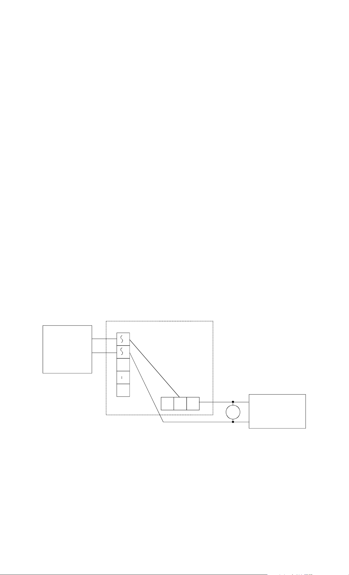
3.3.1 AC LOCK WITH AC POWER
A fail secure lock operating on AC is used. This i s generally an electric strike. “Fail secure”
means that the lock is secure when it is not powered. Power is applied to release the lock.
Referring to figure 2, select a transformer of the same output voltage as the lock (12 or 24
VAC). Make sure the capacity of the transformer is large enou gh to operate both the DK-26 and
the lock and that the transformer is UL listed under the UL 294 standard. The two
transformer secondary wires connect to the “AC inpu t” terminals as shown (there is no polarity
with AC). Power from one terminal then goes to the common of relay #1. The NO contact of
relay #1 will power the lock (releasing the door) when a correct code is entered. Note that AC
locks are normally all fail secure. If you come across a fail safe AC lock (secure when powered)
you would merely make the connection to the lock from the NC1 rather than NO1 terminal.
FIG. 2: AC LOCK - AC POWER WIRING
AC IN F DC IN /OUT
TRANSFORMER
12 OR 24 VAC
+
NC1 C1 NO1
MOV
PN# 500-16900
Page 3 Rev. D, 12/11
AC FAIL SECURE
LOCK
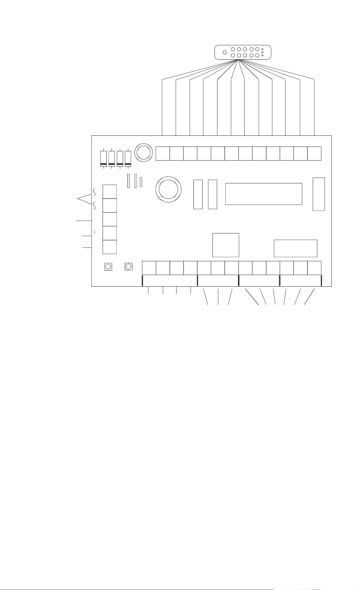
FIG. 3: OVERVIEW OF CPU BOARD
KEYPAD CABLE
12/24 AC POWER
FREE TERM INAL
12/24 DC NEGATIVE
12/24 DC POWER +
AC IN F DC IN/OUT
PS1
PS2
PS3
VIOLET
KEYS
VIO
BEIGE
ORANGE
PINK
KEYS
KEYS
KEYS
GRAY
BROWN
KEYS
KEYS
WHITE
BLACK
COMMON
BLUE
BEEPER
RED
RED LED
YELLOW
YEL LED
GREEN
GRN LED
KEYS
BLK GRY BRN BGE ORG PNK
WHT
GRN YEL RED BLU
MICROPROCESSOR
AUX.
SOCKET
SPDT
+
RELAY
DPDT RELAY
DC TERMINALS MA Y
ALSO BE USED AS
OUTPUT TO POWER
DC LOCK, IF AC
POWER IS SUPPLIED
PRGM
CODE
PUSH TO SET PROGRAM MODE
HARD
CODE
PUSH TO PROGRAM HARD CODE
SRC
COM. FOR REX, UCD, HCD TERMS
UCD HCD NCX CX
REX
REX INPUT (REMOT E R ELE ASE)
DISABLE HARD CODE
DISABLE ALL USER CO D ES
NOX
PROGRAM
RELAY
NC2 C2
NO2
LOCK CONTROL
RELAY CONTACTS
NC1 C1
NO1
CONTACTS
RELAY CONTACTS
RATED AT 5 AMPS
3.3.2 DC LOCK WITH AC POWER
For convenience and economy, most DC electric locks can be operated from an AC transformer
when the DK-26 is used. Select a transformer of the same voltage as the lock (12 or 24). The
CPU board converts the input AC to DC to operate the lock. Make sure the capacity of the
transformer is large enough to operate both the DK-26 and the lo ck and that the transformer
is UL listed under the UL 294 standard. The lock must accept full wave rectified DC
power. This is true of most DC locks (including Securitron’s Magnalocks) but some specialty
units require regulated DC power. You must operate those as described in the next Section.
Note finally that many DC lock installations call for battery backup. To achieve this, you must
employ a DC battery backup power supply and also follow the wiring description in Section
3.3.3.
DC locks come in “fail secure” and “fail safe” versions. A fail secure lock is secure when not
powered and a fail safe lock is secure when powered. All magnetic locks are fail safe. Figure
4 shows AC power being input to the AC terminals. The DC terminals furnish output power for
PN# 500-16900
Page 4 Rev. D, 12/11
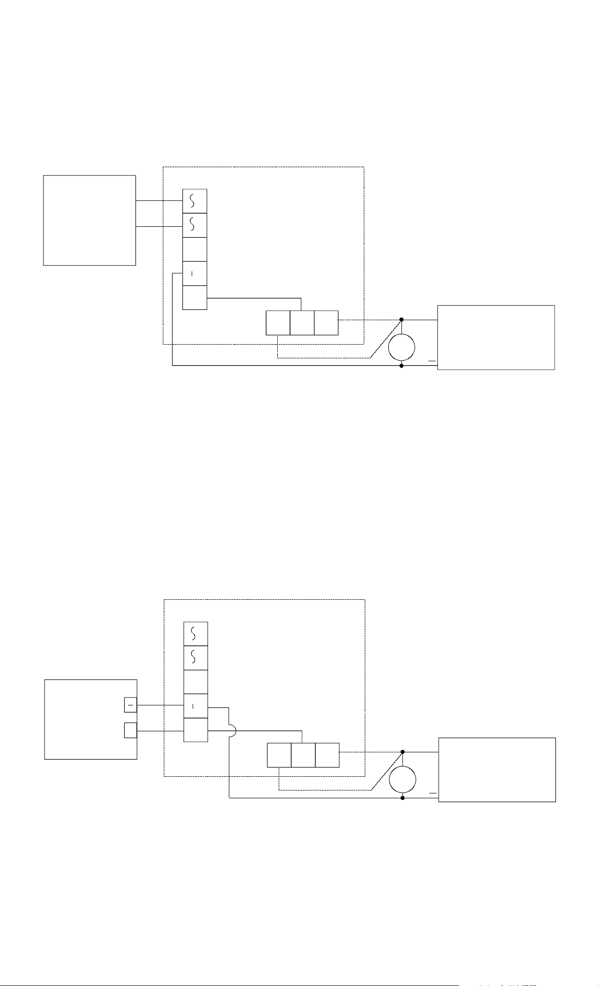
the lock. DC locks operated in this way must not draw more than 2 Amps. The positive
DC terminal connects to the common of relay #1 and either the NO1 te rminal (if the lock is fail
secure) or the NC1 terminal (if the lock is fail safe) connects to the lo ck’s positive power input.
This is shown in dotted lines. You only connect one of these terminals. Note that some DC locks
are polarized and you must connect lock power correctly to positive and negative. Others are
not polarized and can be connected either way. Consult the lock instructions.
FIG. 4: DC LOCK - AC POWER WIRING
AC IN F DC IN /OUT
TRANSFORMER
12 OR 24 VAC
NOTE: MOV NO T REQUIRED IF
+
SECURITRON MAGNALOCK IS U SED
NC1 C1 NO1
DC FAIL SECURE
+
OR FAIL SAFE LOCK
IF FAIL SECURE
IF FAIL SAFE
MOV
3.3.3 DC LOCK WITH DC POWER
Select a power supply of the same voltage as the lock (12 o r 24). Make sure the capacity o f the
supply is large enough to operate both the DK-26 and the lock. The DK-26 does not require
regulated power but certain specialized electric locks do, so follow the rule of matching the
power supply to the requirements of the lock.
DC locks come in “fail secure” and “fail safe” versions. A fail secure lock is secure when not
powered and a fail safe lock is secure when powered. All magnetic locks are fail safe. Figure 5
shows correct wiring. The positive DC terminal connects to the common of relay #1 and either
the NO1 terminal (if the lock is fail secure) or the NC1 terminal (if the lock is fail sa fe) connects
to the lock’s positive power input. This is shown in dotted lines. You only connect one of these
two terminals. Note that some DC locks are polarized and you must be sure to con nect the lock
power wires correctly to positive and negative. Others are not polarized and it doesn’t matter
which way they are connected. Consult the lock instructions.
FIG 5: DC LOCK - DC POWER WIRING
AC IN F
POWER SUPPLY
DC IN /OUT
NOTE: MOV NO T REQUIRED IF
+
12 OR 24 VDC
DC POWER NEED NOT
BE REGULATED
+
NC1 C1 NO1
IF FAIL SAFE
SECURITRON MAGNALOCK IS USED
IF FAIL SECURE
DC FAIL SECURE
+
OR FAIL SAFE LOCK
MOV
PN# 500-16900
Page 5 Rev. D, 12/11
3.4 USE OF THE “F” TERMINAL
A
The F terminal on the power strip is not connected to
anything. It is a free terminal with either of two
intended uses. First, on some complicated
installations, a large number of wires (generally DC
TRANSFORMER
FIRE ALA R M
AC IN F DC IN /OUT
CONTACTS
N
C
C
negative) may require termination. It can be
convenient to run a jumper from the DC- terminal to
the F terminal so that the large number of negative
returns can be spread on to the two terminals.
Second, some magnetic lock installations require
interface with NC contacts controlled by the fire alarm
system which will cut low voltage power
WHEN THE FIRE
ALARM CONTACTS
OPEN, ALL POWER
+
WILL BE RE MO VED
FROM THE DOOR
immediately releasing the magnetic lock for
safety. The connection to the fire alarm contacts is normally made in the power supply but if
you are using a plug in power supply, you’ll want to make the connection on the DK-26 CPU
board where you have terminals. Using the example of a plug in AC transformer. See the
drawing to the right.
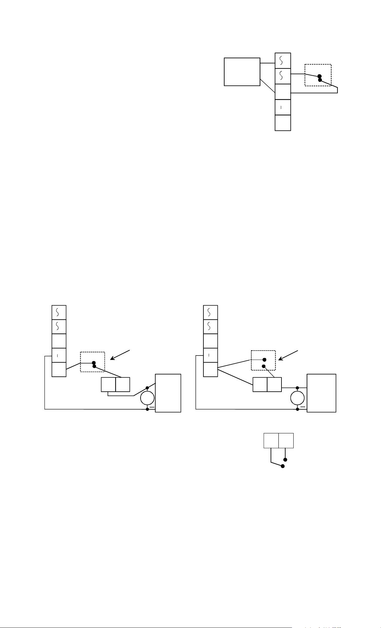
3.5 ADDING OTHER LOCK CONTROL SWITCHES
The drawings in Section 3.3 are valid for simple installations w here the DK-26 is the only control
device that can release the electric lock. Often, however, additional control devices are called
for. The most common is some type of exit switch and this issue is covered in the next
Section. Sometimes other control switches are needed which are not appropriate for the REX
input as use of this input triggers the timed release capability of the DK-26.
A typical example would be a switch located centrally which would release the lock in response
to an intercom call for example. If the lock is fail safe, the switch will need to break power to
the lock and if it’s fail secure, the switch will need to send power to the lock. Figure 6 shows
how to add external contacts for non timed remote release of the lock for both lock types.
FIG. 6: ADDING EXTERNAL CONTACTS FOR FAIL SAFE AND FAIL SECURE LOCKS
AC IN
AC IN F
FOR NON-TIMED REMOTE
RELEASE OF FAIL SAFE
LOCK, PLACE NC C ONTACTS
F DC IN /OUT
IN CIRCUIT AS SHOWN
N
C
+
C
MOV
+
FAIL
SAFE
LOCK
NC1
C1
DC IN /OUT
+
FOR NON-TIMED RE MO TE
RELEASE OF FAIL SECURE
LOCK, PLACE NO CONTACTS
IN CIRCUIT AS SHOWN
O
N
C
NO1C1
MOV
+
FAIL
SECURE
LOCK
3.6 THE REX FUNCTION
Often, when the DK-26 is used, provision must be made to allow
people to use the door freely from the inside. If an electric strike
is used, exit may be accomplished by purely mechanical means
(turning the doorknob). If, on the other hand, a solenoid
operated or electromagnetic lock is used, free exit is only
SRC
REX
N N.O. SWITCH
CLOSING BETWEEN
"SRC" AND "REX"
CAUSES TIMED
RELEASE OF THE
DOOR.
possible if a switch on the inside releases the lock.
Connection of this switch or switches is most easily accomplished by using the DK-26's REX
input terminal (see Figure 2). REX stands for Request To Exit. When a normally open switch
activates the REX terminal, the DK-26's control relay will open the lock for the amount of time
programmed into the DK-26's timer. The result is the same as if the DK-26 was used from the
outside of the door. The REX terminal is activated by being connected to the SRC (voltage
source) terminal. It will also activate if +12 or +24V is input to the terminal from the
DK-26’s external power supply. The drawing to the right shows the simplest connection to
an external normally open momentary switch. Any number of additional switches could be
connected in parallel so that pressing any of them would activate the REX function.
PN# 500-16900
Page 6 Rev. D, 12/11
 Loading...