

Page 1
D
www.securitron.com | techsupport@securitron.com
© 2015, Hanchett Entry Systems, Inc., an ASSA ABLOY Group company.
C
A
1 2 3
A
MODEL
KEYPAD
4 5 6
7 8 9
0 #
*
B
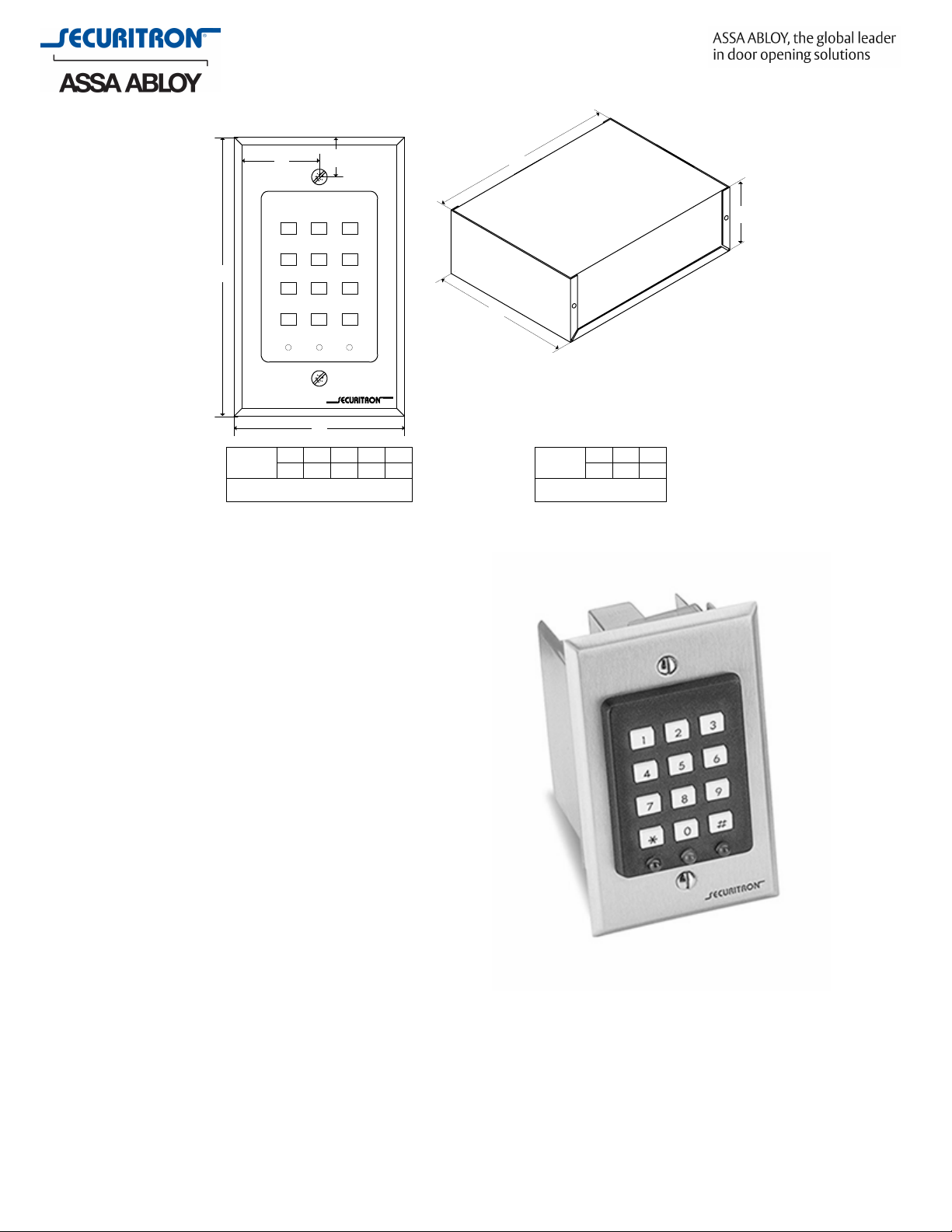
DK-16
A
4.5B2.75C.625D1.375
NOTE: FASTENERS NOT SHOWN ALL
DIMENSIONS IN INCHES.
DEPTH
3
Digital Entry System – DK16
C
B
MODEL
DK-16
NOTE:ALL DIMENSIONS IN
CBO
A
8.25B6C3
INCHES.
Features
• Desi
• Lifetime replac
• Telephone style keypad with green,
• The digital keypad system circuit board
• Unit operates on 12 or 24 volts AC or DC
• The digital keypad system circuit board
• DPDT relay output for lock control and
• Power consumption at rest, 7mA @
gned for high volume indoor use in
con
rolling entry through electrically
t
locked doors
ement warranty
yellow, and red LEDs mounted on face
is a remote unit to allow for increased
security
is mounted in a metal enclosure and
provides for multiple users
alarm shunt, camera call up or other
device interface as well as a REX input
12VDC – 20mA @ 24VDC, power consumption maximum is 160mA @ 12VDC – 190mA
@ 24VDC
Options
• Expansion Circuit Board
• Wiegand output
Page 2
Digital Entry System – DK-16 (cont’d)
www.securitron.com | techsupport@securitron.com
Operating Temperature
(CPU) 0 to 70C [32 to 158F] Keypad 0 to 43C [32 to 110F]
How to Order
Part Number Product Description
DK-16 Digital Keypad System Model 16, Single Gang
DK-16P
DK-16XB Digital Keypad System Model 16 Expansion Circuit Board,
DK-XB Digital Keypad System Model 16/26, Expansion Circuit Board
DK-16W Digital Keypad System Model 16, Wiegand Output, Single Gang
Digital Keypad Model 16, Single Gang
Single Gang
Upg. Kit
ARCHITECTURAL SPECIFICATION – Digital Entry System
Model DK-16
2.x Digital Keypad System – Model DK-16
A. The digital keypad shall be produced by an ISO 9001 certified manufacturer.
B. The digital keypad shall have a lifetime advance replacement warranty.
C. The Digital Keypad shall be of a telephone type with engraved and paint filled
numbers in plastic keys suitable for mounting in a single gang box.
D. The Digital Keypad shall have a red, a green, and a yellow LED mounted on the face.
E. The digital keypad system circuit board shall be a remote unit to allow for increased
security and shall operate on 12 or 24 volts AC or DC.
F. The digital keypad system circuit board shall be mounted in a metal enclosure and
provide for multiple users.
G. The digital keypad shall have a DP/DT relay output for lock control and alarm shunt,
camera call up or other device interface as well as a REX input.
H. Power consumption at rest shall not exceed 7mA @ 12VDC – 20mA @ 24VDC.
I. Power consumption maximum shall not exceed 160mA @ 12VDC and 190mA @
24VDC.
J. The manufacturer shall provide a minimum of sixteen feet of cable to interface the
Digital Keypad with its circuit board, and the system shall have user/installer
programmable options such as anti - tailgate, anti - door prop, and duress code
alarm.
2.x Digital Keypad System – Model DK-16W
K. The Digital Keypad System circuit board shall interface with a PC based access
system via weigand data protocol.
 Loading...