

Page 1
Installation Manual
SECO-LARM
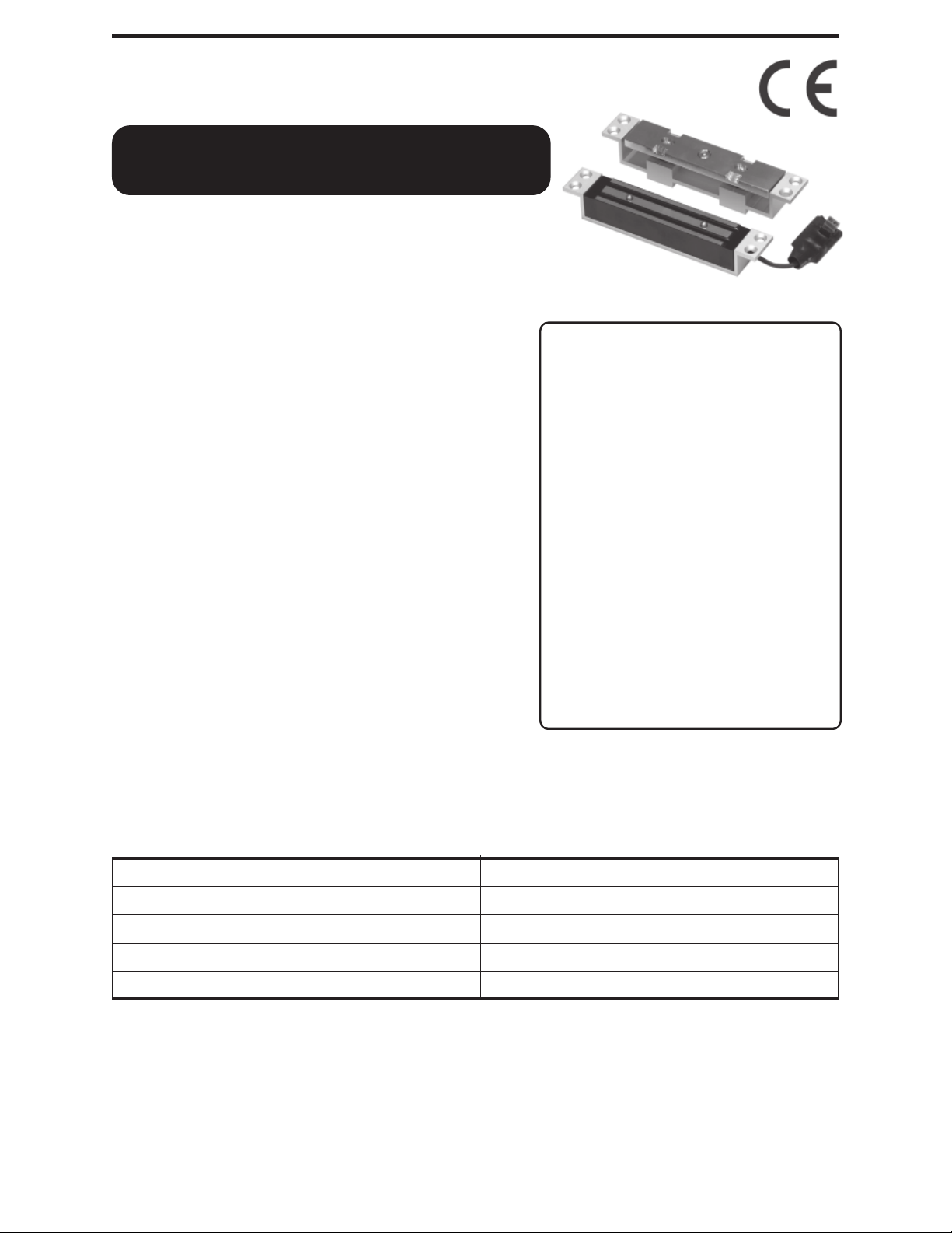
SD-993B-SS
Electric Shear Lock
• Concealed security for remote access and
exit control of aluminum and steel doors
or gates.
• Smaller size for use with most metal
door jambs.
• Zinc-plated magnet and armature,
aluminum anodized housing.
• Works with sliding, single-action, and
double-action (swing-through) doors
and gates.
• Use with an optional digital keypad for
keyless high security.
• Spring-loaded locking bolts and magnetic
bond holds doors securely in place with
approximately 1,500 pounds (680kg) of
shear holding force.
• Fail-safe operation (unlocks if power
is lost).
Bracket kits for SD-993B-SS
Contact your SECO-LARM sales
rep for infomation about
optional bracket kits.
• SD-993S-SB
Surfacemounting kit.
• SD-993S-UB
U-bracket kit
for glass.
See the last page of the
manual for a copy of the
bracket installation manual.
—
—
• Armature plate adjusts to compensate for
gaps between door and frame.
Specifications:
Holding force 1,500 lbs. (680 kg.)
1
Magnet housing dimensions (faceplate) 7
Armature assembly dimensions (faceplate)
Power 420mA @ 12VDC, 210mA @ 24VDC.
Door gap Max. 1/16” (2mm).
IMPORTANT — IT IS THE RESPONSIBILITY OF THE END USER AND THE
DEALER/INSTALLER TO ENSURE THIS UNIT IS MOUNTED IN ACCORDANCE
WITH ALL LOCAL FIRE AND OTHER SAFETY REGULATIONS. THIS UNIT IS
NOT FIRE-RATED.
IMPORTANT — SOME METHOD, SUCH AS A RELAY, MUST BE USED TO
ENSURE DOORS PROTECTED BY THIS UNIT CAN BE OPENED IN CASE OF
AN EMERGENCY.
/8” x 13/16” x 11/16” (180 x 30 x 27 mm).
71/8” x 13/16” x 15/8” (180 x 30 x 42 mm).
Page 2

ELECTRIC SHEAR LOCK Installation Manual
MOUNTING LOCATION (see Fig. 1)
1. Top of door — Mount here for best results, as this allows flexibility against direct
attacks against the door. Mount close to the corner opposite the hinges.
2. Middle of door, opposite the hinges — This works well in most situations. If
mounting is required here, mount halfway up the door for greatest strength. Add
extra springs to the armature assembly (see Fig. 4).
3. Bottom of door — Not recommended, as dirt buildup could affect operation.
INSTALLATION NOTE
Install the magnet assembly into the door frame before installing the armature assembly
into the door. The magnet assembly requires space to run wires, as well as space for the
recessed portion of the unit. However, make sure that the position selected for the
magnet assembly leaves enough room in the door to install the armature assembly.
INSTALLATION — CUT THE DOOR FRAME (see Fig. 2)
1. Find the center line:
a. Close the door and let it rest naturally.
b. Use a pencil to trace the position of the outside face of the door on the door
frame. If mounting on the top of the door, this line should be near the top corner
away from the door hinges. Leave enough room to mount the magnet assembly
in the door. If mounting on the side of the door, this line should be drawn near
the center of the door, but not near any physical locking mechanisms.
c. Measure the width of the door, then draw a line on the door frame parallel to
the first line at that distance. These two lines will show where the door rests
relative to the door frame when it is closed.
d. Measure and trace a line between these two lines. This is the door frame center
line.
e.
IMPORTANT — Make sure the place you choose to mount the magnet assembly is
clear of obstructions and door adjustment bolts before making any cuts. Allow
enough room inside the door frame at both ends of the magnet assembly to
install the mounting tabs.
2. Tape the door frame template to the door frame, lining the template’s door frame
center line with the door center line you just drew.
3. (For hollow metal door frames)
a. Cut out the rectangular piece of metal as shown on the door frame template.
b. Drill the four holes (two on each end) as shown on the door frame template.
c. Using the included metal screws, mount the mounting tabs.
d. Run the wires.
4. (For wood door frames)
a. Rout or cut a 1
of the magnet assembly as shown in the door frame template.
b. Rout a
c. Run the wires.
3
/16” (5mm) deep, 5/8” x 13/16” (17 x 30 mm) hole at each end of the cavity.
1
/16”(27mm) deep, 513/16” x 13/16” (147 x 30 mm) hole for the cavity
SECO-LARM U.S.A., Inc.Page 2
Page 3
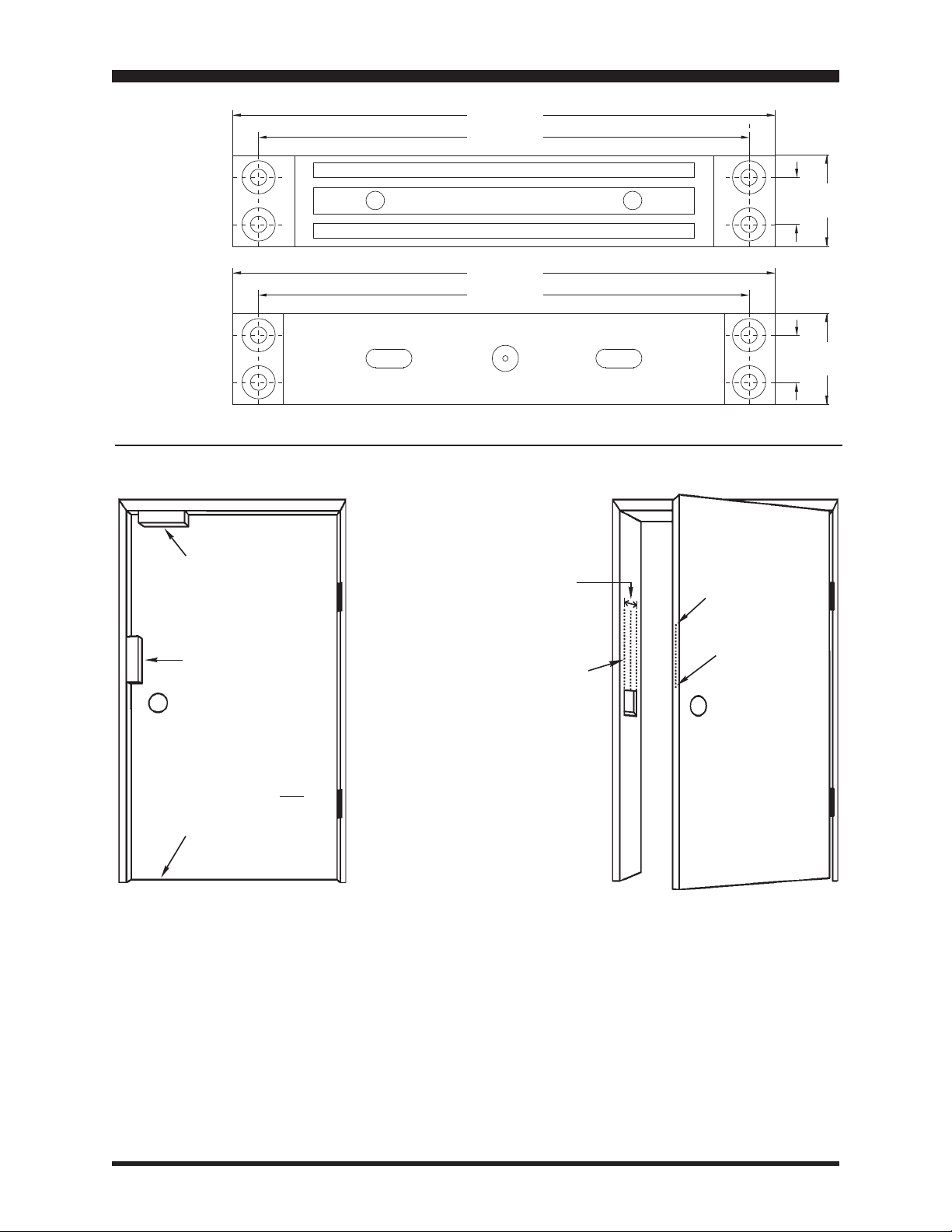
Magnet
ELECTRIC SHEAR LOCK Installation Manual
7-1/8” (180mm)
6-7/16” (164mm)
Assembly
Armature
Assembly
Fig. 1 -Preferred mounting locations
Top of door - BEST
Middle of door GOOD
Note: Add extra
springs for vertical
mount (see Fig. 4)
7-1/8” (180mm)
6-7/16” (164mm)
Fig. 2 -Preparing the mounting positions
Width
of door
Door
center
line
Outside of
door when
closed
5/8”
5/8”
(16mm)
(16mm)
1-3/16”
(30mm)
1-3/16”
(30mm)
Bottom mounting not
suggested
Parts List:
1 x Magnet assembly
1 x Armature assembly
4 x Spacers
2 x Springs (for use
when the SD-993B-SS
is mounted vertically)
16 x Metal screws
1 x Hex wrench
Page 3
Page 4

ELECTRIC SHEAR LOCK Installation Manual
WIRING (see Fig. 3)
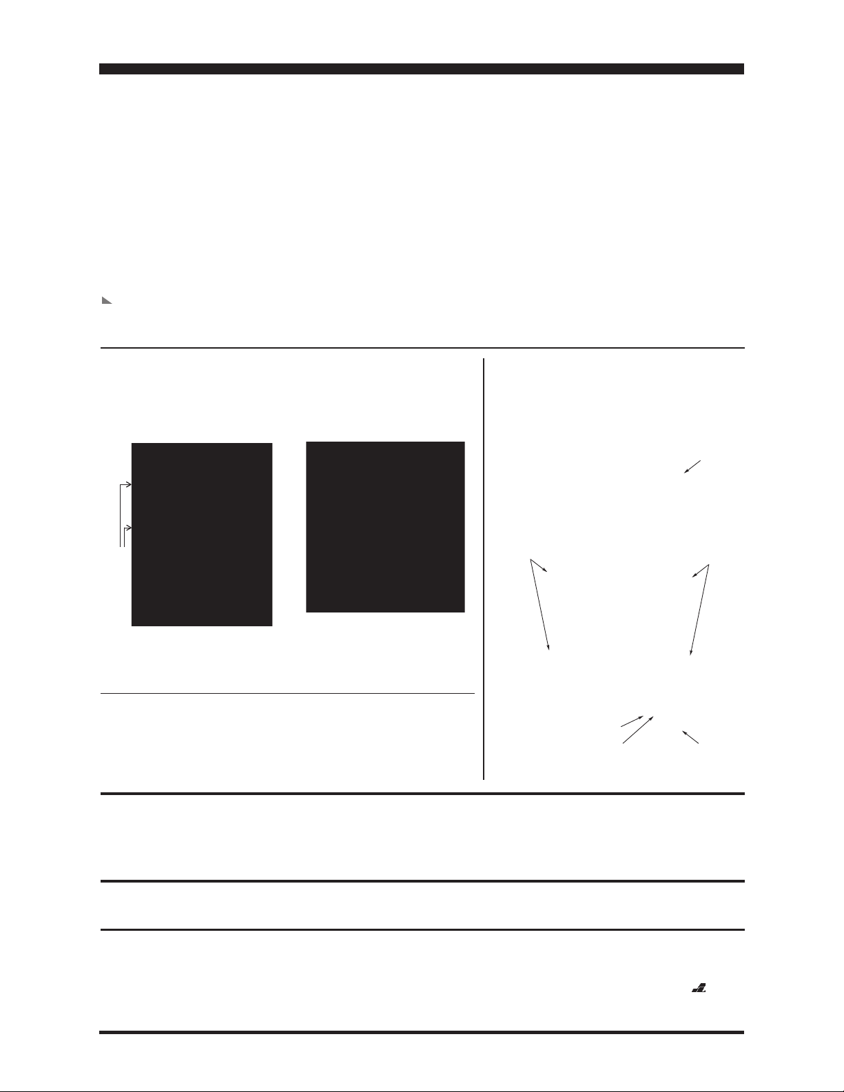
Fig. 3 - Power supply settings and connections
1. Set for power supply type
(12VDC or 24VDC) —
Use the jumpers to set voltage setting.
2. Connect to power —
Power nput
Power
Supply
One terminal positive, one to negative
(non-polarized)
INSTALLATION —
12VDC
24VDC
}
}
Control Device
N.C. contact or relay or keypad
Voltage setting jumpers -- must be
set properly before connecting
power. Incorrect settings can
damage the SD-993B-SS.
CUT THE DOOR
NOTE: When mounting vertically near the center of the door, disassemble the armature
assembly and add the two included springs. This improves the unit’s push-off.
(See fig. 4.)
1. Determine where to mount the armature assembly in the door. It should line up with
the magnet assembly (see Fig. 4).
2. Draw a line between the front and back door faces. This is the door center line
(see Fig. 2).
3. Tape the door template to the door, lining the door template’s door center line with
the door center line you just drew.
4. (For hollow metal doors)
a. Cut out the rectangular piece of metal as shown on the door template.
b. Drill the four holes (two on each end) as shown on the door template.
c. Using the included metal screws, mount the mounting tabs.
5. (For wood doors)
a. Rout or cut a 1
5
/8” (42mm) deep, 513/16” x 13/16” (147 x 30 mm) hole for the cavity
of the armature assembly as shown in the door template.
3
b. Rout a
/16” (5mm) deep, 5/8” x 13/16” (17 x 30 mm) hole at each end of the cavity.
Fig. 4 Lining up magnet assembly and armature assembly
Adjust armature
screws to
compensate for
the gap between
door and frame.
Max. 2mm
gap
Armature
adjustment
screw
7 1/8” (180mm)
5 13/16” (147mm)
MAGNET ASSEMBLY
Locking bolts
Push-off
button
ARMATURE ASSEMBLY
Armature
adjustment
screw
1-1/16”
(27mm)
1-1/16”
(27mm)
1-5/8”
(42mm)
Note — When
mounting vertically,
disassemble the
armature assembly
and add extra
springs for better
push-off.
SECO-LARM U.S.A., Inc.Page 4
Page 5

ELECTRIC SHEAR LOCK Installation Manual
INSTALLATION — MOUNT THE MAGNET ASSEMBLY AND
ARMATURE ASSEMBLY (see Fig. 5)
1. Double-check your work — Make sure the
magnet assembly and armature assembly
line up properly. Make any adjustments.
2. Using the screws provided, mount the magnet
assembly onto the door frame, and the
armature assembly onto the door.
3. Use washers or flat pieces of metal to act as
shims as necessary to mount the magnet
assembly and armature assembly flush with
the surface.
4. Close the door, and note the gap between the
armature assembly and the magnet assembly.
Using the included hex wrench, adjust the
nickelto make the gap as small as possible without
interfering with the opening and closing of
the door.
5. Apply power and test the operation.
plated portion of the armature assembly
Fig. 5 Mounting the magnet assembly and
armature assembly
Use tapping screws
for wood doors
(not included)
Leading edge of door
Fig. 6 Adjustment of SD-993B-SS Electric Shear Lock
Magnet
Min.
2mm
gap
Armature
Use hex wrench (included) to adjust
armature plate to approx. 2mm gap.
Page 5
Page 6

ELECTRIC SHEAR LOCK Installation Manual
TROUBLE SHOOTING
1. If the shear lock does not activate when the door is closed, it may be because the
magnet assembly is too far away from the armature assembly. You can either:
a. Adjust the distance between the magnet and armature assembly by adding more
shims under the back portion of the armature assembly.
b. Re-adjust the position of the armature assembly or the magnet assembly.
2. Poor attraction between the magnet assembly and the armature assembly — Check
the power supply, and make sure it is according to specifications. If the power
supply is adequate, replace the unit.
3. If the magnet assembly pulls the armature assembly, but the door can still be
opened, check to make sure the locking bolts are in the armature assembly’s keeper
hole when the unit is activated.
4. If the door can be kicked in or pushed in with your shoulder, check to make sure the
magnet assembly and armature assembly surfaces are clean and free from dirt. Even
a little dirt could reduce the attraction between the two surfaces.
5. For any other problems, replace the unit, and test again. The problem unit can also
be substituted for a working unit in another door frame to see if it works there.
REGULAR MAINTENANCE
• Clean the contact surfaces of the electromagnet or armature plate with a soft cloth and non-
abrasive, non-corrosive cleaner.
• Apply a light coat of a silicon lubricant to prevent rust. Wipe away the excess.
• Check that the armature plate is securely attached to the door, yet can pivot slightly around the
armature screw.
• Check that the electromagnet is securely attached to the door frame.
WARRANTY:
for a period of one (1) year from the date of sale to the original consumer customer. SECO-LARM’s obligation is limited to the repair or
replacement of any defective part if the unit is returned, transportation prepaid, to SECO-LARM.
This Warranty is void if damage is caused by or attributed to acts of God, physical or electrical misuse or abuse, neglect, repair, or alteration,
improper or abnormal usage, or faulty installation, or if for any other reason SECO-LARM determines that such equipment is not operating
properly as a result of causes other than defects in material and workmanship.
The sole obligation of SECO-LARM, and the purchaser’s exclusive remedy, shall be limited to replacement or repair only, at SECO-LARM’s option.
In no event shall SECO-LARM be liable for any special, collateral, incidental, or consequential personal or property damages of any kind to the
purchaser or anyone else.
This SECO-LARM product is warranted against defects in material and workmanship while used in normal service
NOTICE: The information and specifications printed in this manual are current at the time of publication. However, the SECO-LARM
policy is one of continual development and improvement. For this reason, SECO-LARM reserves the right to change specifications without notice.
SECO-LARM is also not responsible for misprints or typographical errors.
Copyright © 2011 SECO-LARM U.S.A., Inc. All rights reserved. This material may not be reproduced or copied, in whole or in part, without the
written permission of SECO-LARM.
SECO-LARM U.S.A., Inc.Page 6
Page 7

ELECTRIC SHEAR LOCK Installation Manual
Installation Notes:
Date: _____________________________________ Name: ______________________________________
Phone #___________________________________ Company: ___________________________________
Voltage Used:
12VDC 24VDC
Special Circumstances: ___________________________________________________________________
Additional Notes:________________________________________________________________________
Please sketch connection diagram below:
Page 7
Page 8
ELECTRIC SHEAR LOCK Installation Manual
For optional surface-mount bracket and U-bracket kits:
SD-993S-SB
Surface-mount bracket kit
SD-993S-SB
SD-993S-UB
U-bracket (glass door) kit
Bracket kits for SD 993B SS Electric Shear Lock
SD-993S-UB
FOR SURFACE MOUNTING (SD-993S-SB)
Surface-mount
(magnet and armature).
Use 2 x surface-mount brackets
Flush mount (magnet).
Surface mount (door).
Use 1 x surface mount bracket
Header
M6 x 45 screw
Magnet
Assembly
Armature
Assembly
Surface
mount
bracket
The magnet assembly is in
the bracket above the door,
and the armature assembly
is in the bracket on the door.
SD 993S SB includes:
2 x Surface mount brackets
4 x Aluminum trim plates
3 x Blind nuts
3 x Hex screws
1 x Blind nut assembly
Blind Nut
M6 x 45 screw
Blind Nut
Metal
Door
2mm
The magnet assembly is flush to
the door frame or header, and
the armature assembly is in the
bracket on the door.
SD 993S UB includes:
2 x U brackets
8 x Aluminum spacers
4 x Hex screws
1 x Hex wrench
Surface
mount
bracket
Magnet
Assembly
Armature
Assembly
Header
M6 x 45 screw
Blind Nut
Metal
Door
FOR GLASS DOOR MOUNTING (SD-993S-UB)
May require 1 or more SD 993S SB
and SD 993S UB bracket kits,
depending on the glass door
configuration.
Glass
frame
2 x Surface
mount
brackets
Min. gap:
2mm
U bracket
Spacer
NOTES: One glass door with a glass frame illustrated above.
2 x U brackets
Glass
door
Min.
Clearance:
7mm
WARRANTY:
original consumer customer. SECO LARM’s obligation is limited to the repair or replacement of any defective part if the unit is returned, transportation prepaid, to SECO LARM.
This Warranty is void if damage is caused by or attributed to acts of God, physical or electrical misuse or abuse, neglect, repair, or alteration, improper or abnormal usage, or faulty installation, or
if for any other reason SECO LARM determines that such equipment is not operating properly as a result of causes other than defects in material and workmanship.
The sole obligation of SECO LARM, and the purchaser ’s exclusive remedy, shall be limited to replacement or repair only, at SECO LARM’s option. In no event shall SECO LARM be liable for any
special, collateral, incidental, or consequential personal or property damages of any kind to the purchaser or anyone else.
NOTICE
improvement. For this reason, SECO LARM reserves the right to change specifications without notice. SECO LARM is also not responsible for misprints or typographical errors.
Copyright © 2006 SECO LARM U.S.A., Inc. All rights reserved. This material may not be reproduced or copied, in whole or in part, without the written permission of SECO LARM.
EC . ., .S
SECO-LARM U.S.A., Inc.
16842 Millikan Avenue, Irvine, CA 92606
Tel: 800-662-0800 / 949-261-2999 Fax: 949-261-7326
This SECO LARM product is warranted against defects in material and workmanship while used in normal service for a period of one (1) year from the date of sale to the
The information and specifications printed in this manual are current at the time of publication. However, the SECO LARM policy is one of continual development and
:
MiSD-993B-SScEmailb.pmd
Website: www.seco-larm.com
@
E-mail: sales
seco-larm.com
PITGW1
SECO-LARM U.S.A., Inc.Page 8
 Loading...