

Page 1
d
C
WTS-800
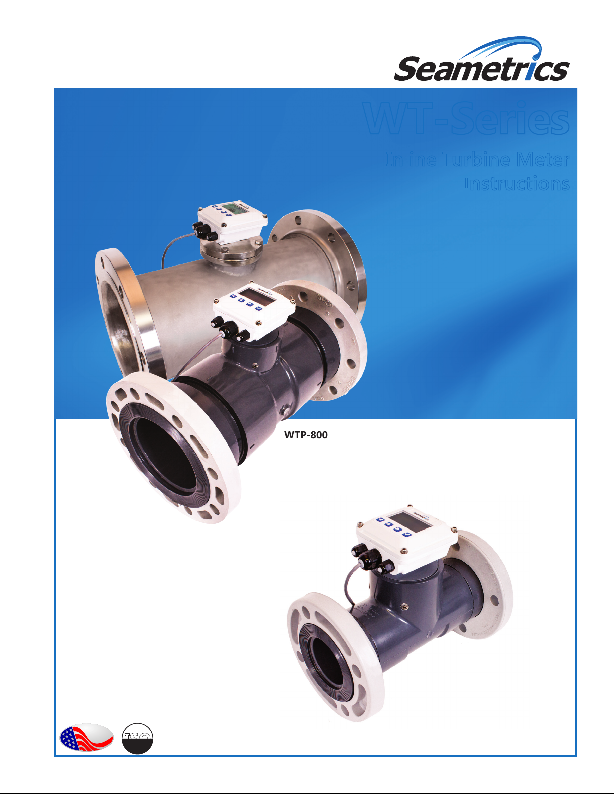
WT-Series
Inline Turbine Meter
Instructions
WTP-800
WTP-400
o
m
e
i
p
f
PROUDLY
MADE
IN THE
USA
i
t
r
e
C
ISO
9001:2008
a
n
y
Page 2

Page 3

TABLE OF CONTENTS
WT-SERIES INSTRUCTIONS
General Information
General Information ...................................................................................................................................................Page 4
Specications ................................................................................................................................................................Page 4
Electronic Options Specications ..........................................................................................................................Page 4
Installation
Installation ......................................................................................................................................................................Page 5
Connections
Connections ...................................................................................................................................................................Page 5
Maintenance and Repair
Recalibration ..................................................................................................................................................................Page5
Turbine Insert Removal and Installation .............................................................................................................Page 5
Rotor and Shaft Replacement .................................................................................................................................Page 5
Sensor Replacement ...................................................................................................................................................Page 5
Replacement Parts.......................................................................................................................................................Page 6
Warranty
Seametrics Limited Warranty ..................................................................................................................................Page 7
Seametrics • 253.872.0284 Page 3 seametrics.com
Page 4

GENERAL INFORMATION
WT-SERIES INSTRUCTIONS
This unique system of 3" to 8" turbine meters uses just one
moving part, a precision helical rotor. Rotation of the rotor is
electronically detected and processed. The high-quality jewel
bearings and shafts minimize friction while providing long life
in non-lubricating uids. The entire rotor assembly can be easily
removed for eld service without removing the meter from the
pipe.
WT meters can be ordered with various output options. The
basic model (100) comes with pulse output only. An electronic
display (Seametrics FT430/440) can be mounted on the 103 and
109 models to display ow rate and total (resettable or non-
resettable), and provide a programmable pulse or 4-20 mA
output. Other electronics options include a blind 4-20 mA
transmitter (AO55) on the 102 model and a battery-powered
(FT450) rate/totalizer plus pulse output for applications that lack
WTP bodies are fabricated from Schedule 80 PVC ttings and
WTS bodies from stainless steel tubing. The turbine insert on
WTS meters is machined from a stainless steel casting. The WTP
turbine insert is machined from a solid piece of PVC. Turbine
power (107 model). All of these controls/displays can be mounted
on the meter or remotely mounted on a wall or panel up to 2,000
feet away. WT-Series meters are compatible for use with other
remote-mount Seametrics displays and controls as well.
rotors on all models are Kynar (PVDF).
Specications*
WTP WTS
Pipe Sizes 3”, 4”, 6” 3”, 4”, 6”, 8”
Materials Meter Body PVC Schedule 80 ttings 304 Stainless steel (316 SS optional)
Turbine Insert PVC CF8 cast stainless
Rotor Kynar® (PVDF) Kynar® (PVDF)
Shaft Zirconia ceramic Zirconia ceramic
Bearings Sapphire journal, ruby endstone Sapphire journal, ruby endstone
Cable #22 AWG, 2000’ max #22 AWG, 2000’ max
Flanges Optional (See dimensions) 150 lb. drilling
Maximum Pressure 150 psi @ 75° F)
(10 bar @ 24° C) (See chart)
Maximum Temperature 120° F (50° C) (See chart) 200° F (93° C)
Accuracy ± 1% of full scale ± 1% of full scale
Flow Range (GPM) 3” 4” 6” 3” 4” 6” 8”
Minimum 3 6 12 3 6 12 30
Maximum 400 600 1200 400 600 1200 3000
Kynar is a registered trademark of Arkema, Inc.
* Specications subject to change. Please consult our web site for current data (seametrics.com).
200 psi (14 bar)
Electronic Options Specications*
WT100 WT102 WT103 WT107 WT109
Power 6-36 Vdc 24-36 Vdc (isolated) 7-30 Vdc Battery (Lithium “C”,
Electronic
Display
Pulse Out 0-160 pulse/sec.
Analog Out 4-20 mA Loop 4-20 mA Loop
Rate 5-digit autorange 5-digit autorange 5-digit autorange
Total 8-digit 8-digit 8-digit
Memory Non-volatile Non-volatile Non-volatile
Response Time 2-60 seconds, 90% full
High/Low Alarm Selectable on one
Regulatory
current sinking
Mark
Seametrics • 253.872.0284 Page 4 seametrics.com
A055 FT430 FT450 FT440
scale, (depending on
input averaging)
Mark
Pulse scaled and pulse
pass through
output
Mark
3.6V, replaceable)
Pulse scaled Pulse scaled
Selectable on one
output
Mark
7-30 Vdc, 4mA
(4-20 mA when loop
powered)
Selectable on one
output
Mark
Page 5

10X Dia. 5X Dia.
Straight coupling can
be part of length
FLOW
WTP
INSTALLATION, CONNECTIONS, MAINTENANCE AND REPAIR
A
WT-SERIES INSTRUCTIONS
Installation
CAUTION: These water meters are not
recommended for installation downstream of
the boiler feedwater pump where installation
fault may expose the meter to boiler pressure
and temperature. Maximum recommended
temperature is 120˚ (PVC) or 200˚ (Metal).
Piping Conditions. Installing the meter with 10 diameters
of straight pipe upstream and 5 downstream is
recommended.
Flanges. For WTS meters, standard anges are 150 lb. ANSI
drilling. PVC meters can be installed with optional anges
according to pipe manufacturer’s recommendations. For
PVC a bolt torque of 20-30 ft-lb for 3” and 4” anges, and
35-50 ft-lb for 6” anges is recommended.
WTP Meter
Meter
Size
NOTE: Flange options faceto-face dimension (“A”) is
the same as plain ends.
Dim ADim
B
3” 12” 6.5”
4” 14” 7.0”
6” 18” 8.5”
Optional
Optional
Flanges
B
A
Flanges
WTS Meter
Meter
Size
3” 12”
4” 14”
6” 18”
8” 20”
Dim A
Flange
150 lb
drilling
Maintenance and Repair
Recalibration. If it is necessary to recalibrate the meter for
any reason, this can be done by any Seametrics-authorized
facility. Call your supplier for information.
Either partial or full-face gaskets can be used. Tighten the
bolts evenly. Use care to prevent a misaligned gasket from
entering the ow stream.
Position. The WT-Series are all-position meters, operable
in a vertical or horizontal position, with the meter insert
in any radial position. A horizontal position is preferred if
there is a risk of air becoming trapped due to constant low
ows. Operating the meter in partially-lled pipe will result
in inaccuracies.
Connections
Loop Power Supply
24-36 Vdc (dep on device)
Black
4-20 mA Device
For operating instructions for the various electronic modules,
consult the manual for the specic module, included with the meter
at purchase.
Red
Black
Black
White
Red
Power
Sensor
Output
Sensor
Pulse
Output
To Other
Control
Turbine Insert Removal and Installation.
CAUTION: First remove all pressure from the line. Then
remove the screws or bolts that hold the insert in place and
tug gently until the insert comes free. A twisting motion
can help to loosen the O-ring seal. Reverse the procedure
to reinstall, after coating the O-ring with lubricant (plastic
compatible in the WTP). Do not overtighten.
Rotor and Shaft Replacement. Examine the rotor to
determine if bearings or shaft are damaged or excessively
worn. The rotor should spin smoothly and freely, with
no visible wobble. Back and forth play should be very
minor, less than 1/64”. If it is necessary to replace the
rotor or shafts, rst back out both shafts with a small
blade screwdriver. The rotor will come free as soon as the
shaft ends come free of the rotor bearings. Reverse the
procedure to reinstall. Note: Do not overtighten the shaft
screws. Check to be sure that a small amount of free play
between the shaft ends and the bearings remains.
Sensor Replacement. This is rarely necessary. However,
certain electrical conditions can damage the sensor. To
replace it, rst remove the electronics module. Disconnect
the sensor leads from the electronics module terminals and
remove the threaded plug over the sensor. Finally, remove
the sensor by pulling on the sensor leads. A gentle tug
should be sufcient. Reverse the process to replace the
sensor.
Seametrics • 253.872.0284 Page 5 seametrics.com
Page 6

MAINTENANCE AND REPAIR
Replacement Parts
WT-SERIES INSTRUCTIONS
White
Housing
1 Upper housing/electronics Contact
2 Housing gasket/seal 102025 100411
3 Lower housing Not eld
Housing screw/washer kit
4
(4 each)
Plug, steel (battery units) 100360 100360
5
6 Strain relief kit, small
(includes 2)
7 Strain relief kit, large
(includes 1)
(externally powered units)
8 Square housing adapter Not eld
9 Pickup retaining screw 100298 100298
Pickup, Micropower* 100508 100508
10
Pickup, Standard 100419 100419
11a Insert, SS N/A 100440
11b Insert, 3” PVC 100438 N/A
11c Insert, 4”-6” PVC 100439 N/A
12 Shaft assembly, ceramic (includes 2) 103312 103312
13 Rotor (PVDF) /bearing assembly 100333 100333
14 O-ring, EPDM 100214 100270
15 Insert screw (4 req’d) 100023 N/A
* For WT100 with an FT450W or a WT107
service
representative
for your
specic model
replaceable
100414 100414
100364 100364
101850 101850
WTP WTS
replaceable
Blue Housing
Contact
service
representative
for your
specic model
Not eld
replaceable
Not eld
replaceable
4
65
1
2
7
3
8
9
10
WTP
WTP
11b
11a
12
13
14
11c
12
13
14
15
FLOW
WTS WTP
WTC/WTS
WTP
Electronics Module Repair. None of the electronics modules have
replaceable components. Printed circuit boards must be replaced
as complete units. In order to replace an entire electronics module,
loosen the four retaining screws and the unit will lift free from the
insert housing.
Seametrics • 253.872.0284 Page 6 seametrics.com
Page 7

SEAMETRICS LIMITED WARRANTY
WT-SERIES INSTRUCTIONS
The limited warranty set forth below is given by Seametrics, with respect to Seametrics and INW brand products purchased in the
United States of America.
Seametrics warrants that products manufactured by Seametrics, when delivered to you in new condition in their original containers
and properly installed, shall be free from defects in material and workmanship. Seametrics products are warranted against
defects for a period of two (2) years from date of installation, with proof of install date. If no proof of install date can be
provided, warranty period will be two (2) years from date of shipment from Seametrics, as dened on Seametrics’ invoice.
Seametrics’ obligation under this warranty shall be limited to replacing or repairing the part or parts, or, at Seametrics’ option, the
products, which prove defective in material or workmanship. The following are the terms of Seametrics’ limited warranty:
a. Buyer must give Seametrics prompt notice of any defect or failure and satisfactory proof thereof.
b. Any defective part or parts must be returned to Seametrics’ factory or to an authorized service center for inspection.
c. Buyer will prepay all freight charges to return any products to Seametrics’ factory, or another repair facility. as designated by
Seametrics.
d. Defective products, or parts thereof, which are returned to Seametrics and proved to be defective upon inspection, will be
repaired to factory specications.
e. Seametrics will deliver repaired products or replacements for defective products to the buyer (ground freight prepaid) to the
destination provided in the original order.
f. Products returned to Seametrics for which Seametrics provides replacement under this warranty shall become the property
of Seametrics.
g. This limited warranty covers all defects encountered in normal use of Seametrics products, and does not apply to the
following cases:
i. Loss of or damage to Seametrics product due to abuse, mishandling, or improper packaging by buyer
ii. Failure to follow operating, maintenance, or environmental instructions prescribed in Seametrics’ instruction manual
iii. Products not used for their intended purpose
iv. Alterations to the product, purposeful or accidental
v. Electrical current uctuations
vi. Corrosion due to aggressive materials not approved for your specic product
vii. Mishandling, or misapplication of Seametrics products
viii. Products or parts that are typically consumed during normal operation
ix. Use of parts or supplies (other than those sold by Seametrics) which cause damage to the products, or cause
abnormally frequent service calls or service problems
h. A new warranty period shall not be established for repaired or replaced material, products, or supplied. Such items shall
remain under warranty only for the remainder of the warranty period on the original materials, products, or supplies.
i. In the event that equipment is altered or repaired by the buyer without prior written approval by Seametrics, all warranties
are void. Damage caused by equipment or accessories not manufactured by Seametrics may void the product’s warranty.
j. SOFTWARE: The Seller grants the user a non-exclusive license to use Seametrics’ software, according to the following
limitations and conditions:
i. The user may install the software on one or more desktop or laptop computers.
ii. All title and intellectual rights to the software are owned by Seametrics.
iii. No copies may be made or distributed except as described above.
iv. The user may not modify or reverse-engineer the software.
THE FOREGOING WARRANTY IS IN LIEU OF ALL OTHER WARRANTIES, WHETHER ORAL, WRITTEN, EXPRESSED, IMPLIED OR STATUTORY.
NO IMPLIED WARRANTY, INCLUDING ANY IMPLIED WARRANTY OF MERCHANTABILITY OR FITNESS FOR A PARTICULAR PURPOSE,
APPLIED TO THE PRODUCTS AFTER THE APPLICABLE PERIOD OF THE EXPRESS LIMITED WARRANTY STATED ABOVE, AND NO OTHER
EXPRESS WARRANTY OR GUARANTY, EXCEPT AS MENTIONED ABOVE, GIVEN BY ANY PERSON OR ENTITY WITH RESPECT TO THE
PRODUCTS, SHALL BIND SEAMETRICS. SEAMETRICS SHALL NOT BE LIABLE FOR LOSS OF REVENUES, OR PROFITS, OR INCONVENIENCES,
EXPENSE FOR SUBSTITUTE EQUIPMENT OR SERVICE, STORAGE CHARGES, LOSS OF DATA, OR ANY OTHER SPECIAL, INCIDENTAL, OR
CONSEQUENTIAL DAMAGE CAUSED BY THE USE OR MISUSE OF, OR INABILITY TO USE THE PRODUCTS, REGARDLESS OF THE LEGAL
THEORY ON WHICH THE CLAIM IS BASED, AND EVEN IF SEAMETRICS HAS BEEN ADVISED OF THE POSSIBILITY OF SUCH DAMAGES. IN NO
EVENT SHALL RECOVERY OF ANY KIND AGAINST SEAMETRICS BE GREATER IN AMOUNT THAN THE PURCHASE PRICE OF THE PRODUCT
SOLD BY SEAMETRICS AND CAUSING THE ALLEGED DAMAGE. WITHOUT LIMITING THE FOREGOING, YOU ASSUME ALL RISK OF LIABILITY
FOR LOSS, DAMAGE, OR INJURY TO YOU AND YOUR PROPERTY AND TO OTHERS AND THEIR PROPERTY ARISING OUT OF USE OR MISUSE
OF, OR INABILITY TO USE THE PRODUCTS NOT CAUSED DIRECTLY BY THE NEGLIGENCE OF SEAMETRICS.
SOME STATES DO NOT ALLOW LIMITATIONS ON THE DURATION OF AN IMPLIED WARRANTY, SO THE ABOVE LIMITATIONS MAY NOT
APPLY TO YOU. SIMILARLY, SOME STATES DO NOT ALLOW THE EXCLUSION OR LIMITATIONS OF CONSEQUENTIAL DAMAGE, SO THE
ABOVE LIMITATION OR EXCLUSION MAY NOT APPLY TO YOU. THIS LIMITED WARRANTY GIVES YOU SPECIFIC LEGAL RIGHTS; HOWEVER,
YOU MAY ALSO HAVE OTHER RIGHTS WHICH MAY VARY FROM STATE TO STATE.
Seametrics • 253.872.0284 Page 7 seametrics.com
Page 8

Seametrics • 19026 72nd Avenue South • Kent, Washington 98032 • USA
(P) 253.872.0284 • (F) 253.872.0285 • 1.800.975.8153 • seametrics.com
LT-65200056r2.0 20170110
1/10/17
 Loading...