

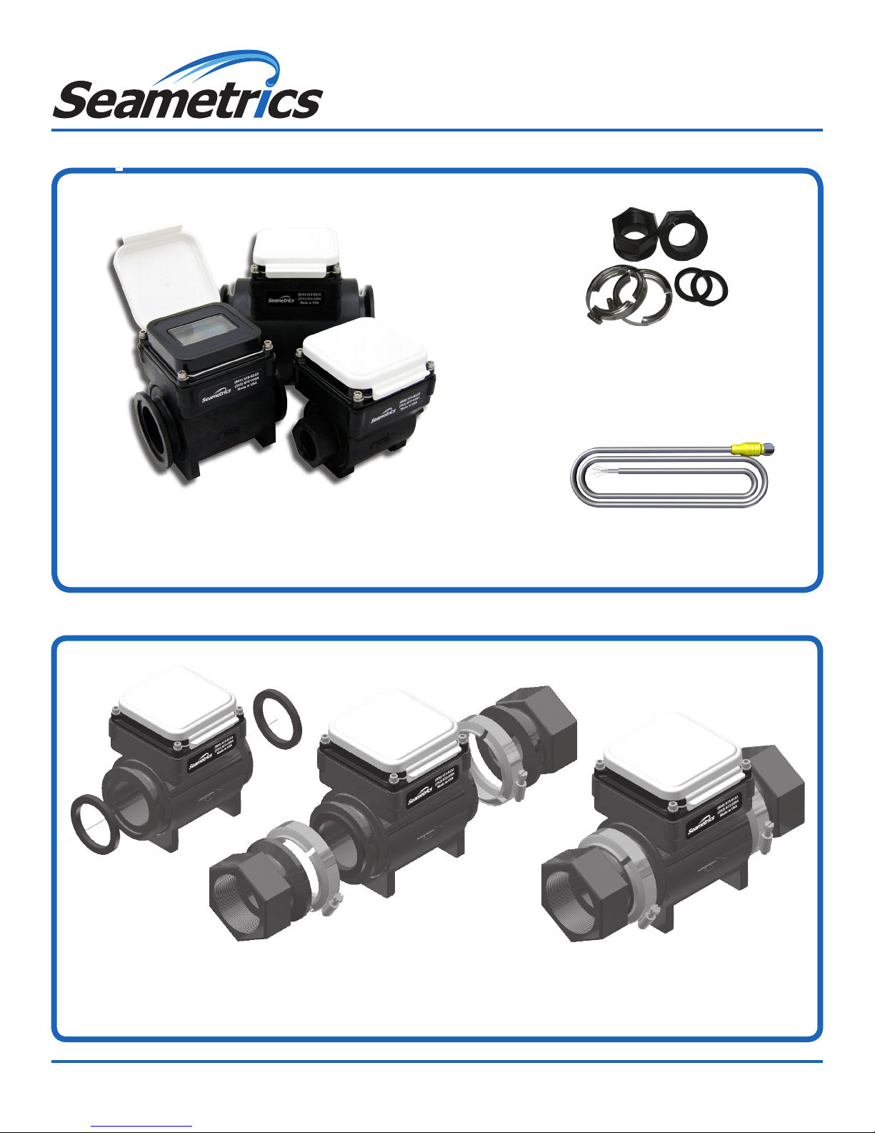
Components
2 inch
WMP-Series
Quick Start Guide
3 inch
Fitting Kit
(2” and 3” models only)
1 inch
Meter and Indicator
End Connections
Step 1
Position gasket
at either end
Step 2
Place adapter
against gasket,
open screw clamps
to clear anges
Power/Output Cable
(WMP101 only)
Step 3
Place screw-clamps
over both adapter
and meter anges
and tighten screws
NOTE: Above installation instructions are for WMP101/104-200 (2”) and WMP101/104-300 (3”) only.
The WMP101/104-100 (1”) is provided with integrated NPT female threaded ends.
253.872.0284 seametrics.com
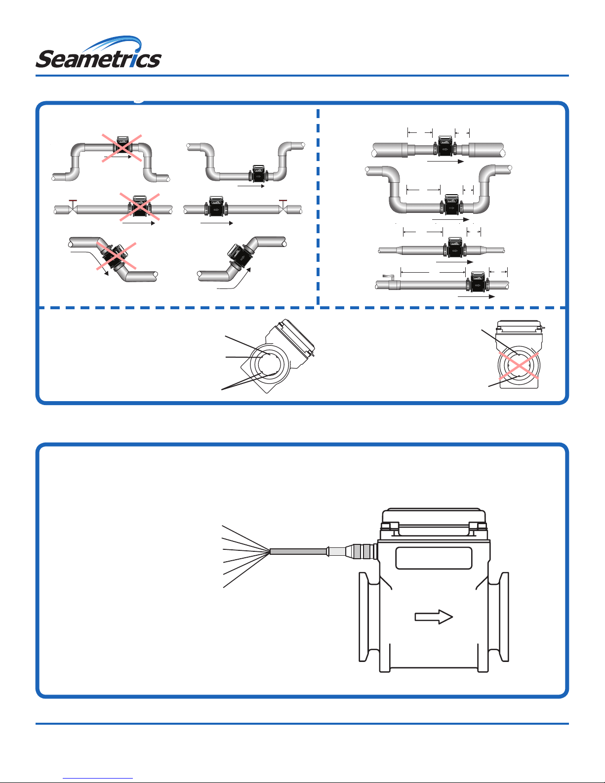
Positioning
Choose a position that will ensure a full pipe. Choose a position that will minimize ow distortion.
WMP-Series
Quick Start Guide
2X
1X
Recommended:
May prevent sediment
or bubble problems
Intermittent air
bubbles miss electrode
Electrode moved from
top by rotating meter
Not Ideal:
Air bubbles and
sediment on the
electrodes can affect
accuracy
Electrodes free from
sediment build-up
Electrical Connections
WMP101:
Plug the cable into the meter and hand tighten. Follow the diagram to make
connections. If you are using pulse output, connect power rst and determine that the
meter is working properly by observing the display. Then connect the pulse output.
2X
5X
5X
1X
1X
Intermittent air
bubbles pass
over electrode
Possible
sediment
build-up
WMP104:
No connections needed.
1X
Gray: Pin 5 = Ground
Black: Pin 4 = (–) Power
Blue: Pin 3 = (+) Pulse
White: Pin 2 = (–) Pulse
Brown: Pin 1 = (+) Power
Shield Drain Wire
Grounding (WMP101):
For best performance, especially in chemically noisy
environments, the gray ground wire and the bare drain wire
should be connected together and to a good earth ground
as close to the meter as possible. Metal pipe and ttings in
contact with the uid should also be bonded to the same earth
ground with corrosion-resistant connections.
Seametrics • 19026 72nd Avenue South • Kent, Washington 98032 • USA
(P) 253.872.0284 • (F) 253.872.0285 • 1.800.975.8153 • seametrics.com
LT-14391r1.0 20161006
10/6/16
 Loading...