

Page 1

WJ-Series
TURBINE METER
INSTRUCTIONS
WJ-SERIES TURBINE METER INSTRUCTIONS
ISO
6” Meter
3” Meter
9001:2008
CERTIFIED COMPANY
Page 2
GENERAL INFORMATION and SPECIFICATIONS
GENERAL INFORMATION
WJ-Series turbine meters are dry-register mechanical totalizers
that offer accurate, economical reading of high ows with low
pressure loss. The horizontal-axis turbine drives a vertical
shaft, which is magnetically coupled to the sealed register.
In addition to mechanical totalizing, registers can be equipped
with magnetic pulse reed sensors well suited for remote totalizing, pacing of electronic metering pumps, and water treat-
ment applications.
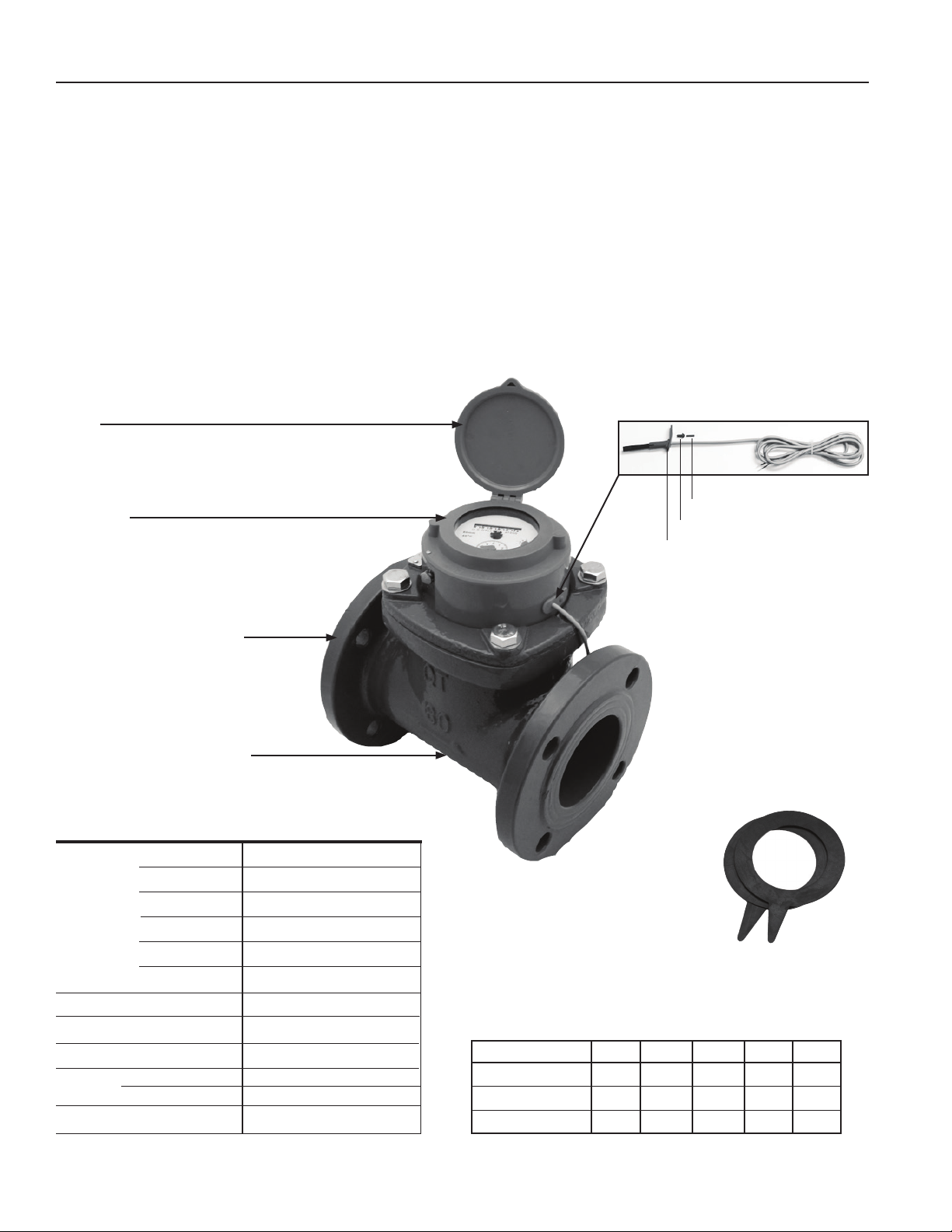
FEATURES
Lid
Display
Bodies are manufactured of tough cast iron and epoxy-coated
for protection. Tungsten steel shafts and jewel bearings further
enhance the durability of these meters. Simple removal of the
top ange brings out all parts for inspection, repair, or replacement. The meter has a tamper-evident seal to call attention to
unauthorized access.
Compatible Seametrics controls include the PT35 pulse timer,
the PD10 pulse divider, and the PS40 pulse splitter for running
multiple pulse-responsive devices (e.g. pumps, counter timers
and remote totalizers) with a single WJ meter.
Rivet Pin #103107
Rivet, plastic #103106
Reed Switch Assembly #103109
150 lb. ANSI drilling ange
Epoxy-coated cast iron body
SPECIFICATIONS
Materials Meter Body
Register Plate
Drive Magnet
Turbine
Turbine Shafts
Bearings
Flanges
Maximum Pressure
Maximum Temperature
Accuracy* Above Transition
Below Transition
Reed Switch
*Specications subject to change
Please consult our website for current data (www.seametrics.com).
Cast iron, epoxy coating
ABS plastic
Alnico
Plastic
Tungsten steel
Jewel
150 lb. ANSI drilling
150 psi (10 bar)
105˚ F (40˚ C)
+/-2% of reading
+/-5% of reading
100 mA @ 24 Vac/dc
3” Meter
Gaskets
included
FLOW RANGE (GPM)
2" 3" 4" 6” 8”
2 5.3 8 20 33
Minimum
Max. Continuous
132 352 528 1320 2200
13 35 53 132 220
Transition*
*The ow rate at which accuracy changes from +/-2% of reading
(above Transition) to +/-5% of reading (below Transition).
Page 2
Page 3

INSTALLATION
The following installation recommendations are adapted from
the American Water Works Manual M6, and will result in the
best meter life and accuracy.
Piping Conditions. It is recommended that the meter be in-
stalled with at least ten diameters of straight pipe upstream
and ve diameters downstream from elbows, tees, crosses,
valves, and other ttings. If less straight pipe is available, or if
debris are likely to go through the meter, installation of a standard plate-type strainer directly upstream is recommended.
If a basket-type strainer is used, it should be located at least
ve diameters upstream. Avoid conditions of trapped air or
partially-lled pipe. This can occur when there is low ow and
open discharge near to the meter.
10X Dia. 5X Dia.
Flanges. The WJ meter is compatible with any standard 150
lb. ANSI drilling, at or raised face. Take care that gaskets
(included) do not protrude into the meter due to misalignment.
Adhering the gasket to the meter ange with gasket adhesive
is a good practice that will aid installation.
Position. WJ-Series are all-position meters, and can be installed horizontally or vertically. Horizontal with register facing
up is recommended when possible.
Flow
Flow Arrow
DIMENSIONS
H H1 H2
L
2” 3” 4”
7.87” (19.99 cm) 8.86” (22.5 cm) 9.84” (24.99 cm)
L
10.08” (25.60 cm) 10.87” (27.61 cm) 11.26” (28.60 cm)
H
12.91” (32.79 cm) 13.70” (83.29 cm) 14.09” (35.79 cm)
H1
15.79” (32.79 cm) 15.75” (40 cm) 15.75” (40 cm)
H2
26.5 lbs (12.02 kg) 35.3 lbs (16.01 kg) 39.7 lbs (18.01 kg)
Wt.
H1 = Lid clearance for reading display
H2 = Head clearance for replacing turbine insert
2", 3", 4"
H H1 H2
L
6” 8”
11.81” (30.00 cm) 13.78” (35.00 cm)
L
13.60” (34.54 cm) 14.67” (37.26 cm)
H
16.44” (41.76 cm) 17.50” (44.45 cm)
H1
1969” (50.01 cm) 19.69” (50.01 cm)
H2
92.6 lbs (42.00 kg) 141 lbs (63.96 kg)
Wt.
H1 = Lid clearance for reading display
H2 = Head clearance for replacing turbine insert
6", 8"
Page 3
Page 4

MAINTENANCE AND REPAIR
CAUTION: Before breaking the tamper-
evident seal on your meter, be sure that
you are in compliance with any regulatory
requirements (if applicable).
Adding Reed Switch. For the contacting head option, WJ
meters use a meter-mounted reed switch to provide a twowire dry contact. To add a reed switch in the eld, remove
one of the black rubber plugs from the side of the register
housing and slide the reed switch assembly into the housing in the direction of the dial with the desired pulse rate.
Lock in place with the rivet and pin (see page 2).
Note: If changing the pulse rate, you need to rst remove
the reed switch from the position it is in. In doing so, the
small plastic rivet & pin will be damaged and should not
be reused. Have a replacement plastic pin & rivet before
beginning. If you do not have a spare, contact factory for
a replacement (see page 2 for part reference).
Changing the Pulse Rate. When changing the pulse rate, you
must rst remove the existing reed switch (see note above).
Recalibration. For meters used for revenue-billing purposes,
some states require periodic calibration checking. This type
of turbine meter is most commonly checked every four years.
Testing may be done by a local mobile meter service or in a
private or municipal meter shop. Changes in calibration should
be made at an authorized meter shop.
The Register (2”, 3” & 4” version shown)
Cover Hinge
Retaining ring
0 0 0 0 0 0
U.S. GALLONS X1000
80mm
40°C
0
1
9
8
1
2
2
3
7
46
5
3
5
4
0
9
1
2
8
3
7
46
5
X 100
X 10
8
7
6
Totalizer
2”, 3” & 4” = X1000
6” & 8” = X10000
Pulse rate dial #1
2”, 3” & 4” = X100
6” & 8” = X1000
Pulse rate dial #2
2”, 3” & 4” = X10
6” & 8” = X100
1. Choose desired pulse rate and switch position.
Setting Your Pulse Rate
Size Size Pulse Reed Switch
(inches) (mm) Rate Position
2” 50
3” 80
4” 100
6” 150
8” 200
100 x10
1,000 x100
100 x10
1,000 x100
100 x10
1,000 x100
1,000 x100
10,000 x1,000
1,000 x100
10,000 x1,000
2. Remove the black rubber plug from the other hole
and move it to the position the reed switch was
removed from.
3. Insert the reed switch assembly into the side of the
register housing in the direction of the dial with desired
pulse rate.
4. Lock in place with rivet and pin.
Register Removal. Clip and remove the copper security wire
from the security pin. Remove the security pin that holds
the lid in place, twist the lid and lift it off. Lift the register
free from the meter, noting orientation.
Turbine Insert Replacement. The entire turbine insert comes
out as a unit without removing the meter from the pipe. Carefully
noting position and retaining parts for reassembly.
1. Remove the lid and register as described.
2. After relieving pressure inside the meter, remove
the four ange hex-screws and washers.
3. Lift the ange and insert out in one piece, rocking
gently to break the seal.
4. Remove the four retaining ring screws, and lift
the retaining ring and ange off the turbine insert.
5. Remove and replace the large O-ring around the
top opening of the meter body.
6. Reassemble the retaining ring and ange on top of
the new insert. Be sure the alignment notch in the
retaining ring is directly above the screw in the
insert’s top plate.
7. Replace the entire mechanism in the meter body
with the drilled screw head in the same corner as
the security pin.
8. Replace the lid with a twist of the wrist, insert
the security pin in the tiny hole in the retaining ring,
and thread the security wire through the screw
head and the security pin. Afx lead seal and crimp.
Page 4
Seametrics Incorporated • 19026 72nd Avenue South • Kent, Washington 98032 • USA
(P) 253.872.0284 • (F) 253.872.0285 • 1.800.975.8153 • www.seametrics.com
LT-65200309-081314
8/13/2014
 Loading...