

TX800-Series
ISO
FLOW SENSOR
INSTRUCTIONS
•TX81x
•TX82x
TX800SERIES FLOW SENSOR INSTRUCTIONS
9 001:2008
CERTIFIED COMPANY

TABLE OF CONTENTS
TX800 SERIES INSTRUCTIONS
General Information
Generial Information, Features .................................................................................................................................Page 3
Specications ..............................................................................................................................................................Page 4
Installation
Fitting Installation, Distorted Flows, Meter Installation, Orienting the Meter .......................................................Page 5
Straight Pipe Recommendations ..............................................................................................................................
Full Pipe Recommendations ......................................................................................................................................Page 7
Connections
FT430, FT440 ............................................................................................................................................................. Page 8
FT450, Connecting to PLC's ......................................................................................................................................Page 9
Operation and Maintenance
Modularity, Output, Fittings, Minimum Flow, Flow Rate Tables, Calibration (“K-Factor”) ..................................Page 10
Rotor Replacement, Signal Troubleshooting, Sensor Replacement ....................................................................Page 11
Parts List ...................................................................................................................................................................Page 12
Troubleshooting
Problem, Probable Cause, Things to Try .................................................................................................................Page 13
Page 6
TABLES AND DIAGRAMS
Features ......................................................................................................................................................................Page 3
Specications ..............................................................................................................................................................Page 4
Distorted Flows, Orienting the Meter ........................................................................................................................ Page 5
Straight Pipe Recommendations ..............................................................................................................................
Full Pipe Recommendations ......................................................................................................................................Page 7
Connection Diagrams ..............................................................................................................................................Page 8-9
Flow Rate Table .........................................................................................................................................................Page 10
Rotor Replacement ...................................................................................................................................................Page 11
Parts Explosion, Parts List .......................................................................................................................................Page 12
Troubleshooting ........................................................................................................................................................Page 13
Page 6
Page 2
Seametrics • 253.872.0284 • www.seametrics.com
GENERAL INFORMATION
TX800 SERIES INSTRUCTIONS
The TX800-Series are insertion turbine meters designed for use
in 1-1/2" to 8" pipe. High-quality jewel bearings and precision
shafts ensure long life and low friction. Available in 316
stainless steel, brass and PVC, sensor bodies are machined
from solid rod for maximum low-ow performance. The TX800Series use special ttings that ensure ease of installation and
correct depth setting in the pipe.
The rotation of the turbine is detected by a non-drag Hall-effect
sensor. Output is a pulse-type square wave, which can be sent
long distances (up to 2,000 feet) without a transmitter. This
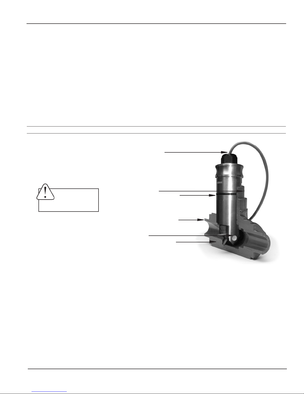
Features
Cable-Seal Strain Relief
signal can be connected directly to Seametrics controls and
displays, as well as PLC's, counters, and computer cards.
Seametrics TX800 meters are ideal for chemical proportioning
applications. If no display is required, a simple divider such as
the PD10 provides adjustable pump pacing. For rate and total
display, as well as pump pacing, the FT420 ow indicator can
be mounted directly on the TX800-Series, or remotely on a wall
or panel. The FT415 offers a battery-operated rate/totalizer
where power is not available.
Caution: U-clip
must be installed
before use.
U-Clip Insertion Point
O-Ring
Fitting
Bearing Housing
Rotor
Seametrics • 253.872.0284 • www.seametrics.com
Page 3

GENERAL INFORMATION
Specications*
Pipe Sizes EX11x/15x: 3” to 10” EX21x/25x: 10” to 48” (up to 72” optional)
Materials Shaft/Fitting 316 SS or Brass
Electrodes Hastelloy
Electrode Cap PVDF
Housing Cast powder-coated aluminum
Valve Assembly (15x/25x only) Bronze (stainless optional) with bronze ball valve
O-Ring (15x/25x only) EPDM
Power Full Power 12-25 Vdc, 250 mA
Low Power 12-25 Vdc, 40 mA average with 250 mA peaks
Flow Range 0.28 to 20 ft/sec (0.08 - 6.09 m/sec)
Fitting Size Required
Temperature Ambient 0˚ to 160˚F (-17˚ to 72˚C)
Fluid 32˚ to 200˚F (0˚ to 93˚C)
EX11x/21x EX15x/25x
1-1/2” FNPT 2” FNPT
TX800 SERIES INSTRUCTIONS
Pressure 200 psi (14 bar)
Minimum Conductivity 20 microSiemens/cm
Calibration Accuracy +/- 1% of full scale
Output
Empty Pipe Detection Software, defaults to zero ow
Regulatory
Square wave pulse, opto isolated, 550 Hz@20ft/sec 6mA max, 30 Vdc forward
ow standard; reverse ow optional
*Specications subject to change. Please consult our website for the most current data (www.seametrics.com).
Page 4
Seametrics • 253.872.0284 • www.seametrics.com
INSTALLATION
TX800 SERIES INSTRUCTIONS
Fitting Installation
TX800-Series meters require special ttings. The meter tting
must rst be installed in the pipeline. Straight pipe of at
least ten times the diameter upstream of the meter and ve
diameters downstream is strongly recommended in order to
achieve proper accuracy. These are minimum values. As the
diagrams on the the next page will show, you may need more
straight run under specic adverse circumstances.
If you can’t provide enough run to smooth out the turbulence
caused by valves, ttings, and changes in direction, some
decrease in accuracy may result. This does not mean that
the ow meter’s reading is meaningless, however. In some
applications (for instance, where the ow meter is part of
a control system, operating a valve or controlling chemical
addition), a repeatable reading may be more important than
a highly accurate one.
TX800-Series PVC meter tees are supplied with some
upstream straight pipe. The length provided may be less
than ten diameters upstream and ve downstream. It is not
advisable to connect directly to the end of these ttings with
a ow-disturbing device such as a valve or elbow. If possible,
straight pipe should be added to the upstream end of these
ttings.
Meter Installation
After the meter tting is installed in the pipeline, the meter
can be installed in the tting. After noting the direction of the
ow arrow, press the meter into the tting as far as it will go.
Retain the meter in place by inserting the U-clip. The pin can
be installed from either side. It may be necessary to rotate the
probe back and forth slightly to start the pin into the slots on the
probe. Slide the pin in as far as it will go.
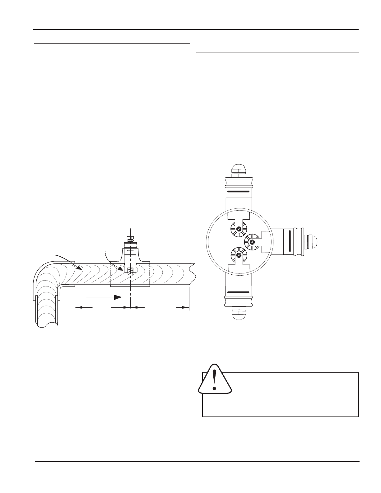
Horizontal (3 o’clock or 9 o’clock position) is the preferred
installation orientation, since it improves low-ow performance
and avoids problems with trapped air and sediment. (See
Orienting the Meter diagram below.) Bottom (6 o’clock), top
(12 o’clock), and vertical pipe installations are all acceptable if
required by the piping layout.
Fair
Unacceptable if pipe
contains air
Faster flow causes
Distorted flow
profile
meter to read high
FLOW
10X
Diameter Minimum
Distorted Flows
Diameter Minimum
A PVC tting is usually installed by solvent welding. The
stainless steel and brass meter ttings have female pipe
threads, requiring the appropriate male threaded ttings.
Saddle ttings (size 3” and above) require a hole to be cut in
the pipe. The recommended hole size is 1-3/4”.
5X
Best
Position
Fair
Unacceptable if pipe
contains sediment
Orienting the Meter
Caution: Never remove the u-clip retainer when
the pipe is under pressure. Always remove
pressure from the pipe before you attempt to
remove the meter. Removal under pressure
may result in damage or serious injury.
Seametrics • 253.872.0284 • www.seametrics.com
Page 5
 Loading...