


S-Series (SPX, SPT)
ARCHIVED
Low Flow Meter Instructions
General Information
These versatile impeller flowmeters in 3/8" to 1"
nominal pipe size employ jewel bearings for very low
minimum flows. The 6-24 VDC pulse output of these
meters is compatible with many different types of
control, including a full range of SeaMetrics rate displays
and controls. The SeaMetrics FT420 provides flow rate
and total flow, with 4-20 mA ouput. For metering pump
pacing or interfacing with lowspeed counters, the PD10
divider is recommended. The AO55 is a blind 4-20mA
transmitter.
S-Series meters are available in 3/8" to 1" nominal sizes.
The SPX body material is polypropylene, with transparent acrylic covers for visual flow indication.
Polypropylene covers are available as an option.
The SPT is available standard with TFE housing, TFE
cover, PVDF rotor, ceramic shaft, choice of o-ring
material (EPDM or Viton), and optional silicon carbide
shaft.
Specifications
Connections
3/8", 1/2", 3/4", 1"
Female NPT standard,
SAE thread optional
Materials
Body SPX: Polypropylene,
SPT: TFE
Cover SPX: Acrylic, Polypro optional
SPT: TFE
Rotor PVDF
Shaft SPX: Nickel tungsten carbide,
zirconia ceramic optional
SPT : zirconia ceramic, silicon
carbide optional
Bearings Ruby
Max. T emperature 160° F (70°C)
Max. Pressure 150 PSI (10 bar)
Accuracy ±1% FS
Flow Rates
Size GPM LPM
3/8" 0.07 - 5 0.27 - 18.9
1/2" 0.1 - 10 0.38 - 37.9
3/4" 0.2 - 20 0.75 - 75
1" 0.5 - 40 1.90 - 150
Features
Removable thread-in
18 ft. standard cable
Standard acrylic top
provides sight flow
indication
3/8"-1" NPT ports
machined into body
sensor 12 VDC pulse
for superior wear
Kynar rotor
Jewel bearings
and flow range
LT-10624A
Page 1 of 2
Installation
ARCHIVED
Repair
Piping Requirements. Standard fittings are female NPT .
If the piping connected to the meter is metallic, care
should be taken not to overtighten. Straight pipe of at
least five diameters upstream of the meter is recommended. Vertical, horizontal, or inverted (lens down)
installations are all acceptable.
Warning: This meter has lowfriction bearings. Do not at any
time test operation of the meter
with compressed air. Doing so
will subject it to rotational
speeds many times those for
which it was designed, and will certainly damage
the rotor, shaft, and/or bearings.
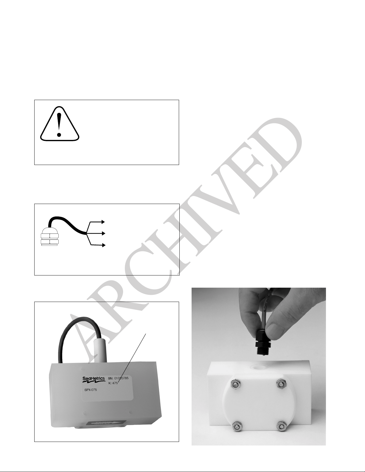
Electrical Connections. There are three conductors to
the sensor, two for positive and negative power and one
for the signal. See the diagram below for color coding.
(BLACK) Power (-)
Rotor Replacement. There is only one moving part to
this meter. The bearings are made of ruby , which rarely
wears out, and will not need replacement unless they
have been physically damaged by severe shock. The
shaft is integrally molded into the rotor, and shaft and
rotor are replaced as one part. To replace the rotor,
remove all pressure from the meter. Then remove the
four screws which hold the lens (or cover) in place. Lift
the lens, then remove the rotor. When putting in the
new rotor, be sure that the end of the shaft is started
into the bearing before the lens is put into place.
When putting on the lens, be sure that the shaft is
also started into the upper bearing before lowering the lens into place. If any resistance is met
when the lens is replaced, the shaft is not started
into one of the bearings. Check that the lens oring is also in place, then replace the four screws
and tighten.
Sensor Replacement. The sensor ordinarily does not
need replacement unless it is electrically damaged. If
replacement is necessary, unthread the sensor by
hand. Thread the replacement sensor in and tighten
by hand.
SPX sensor connection
Nominal K-factor
(WHITE) Signal
(RED) Power (+) 6-24 VDC
Field Replacement of Sensor
K-factor on
model/serial
label on back
2 of 4
 Loading...