

Page 1
SES
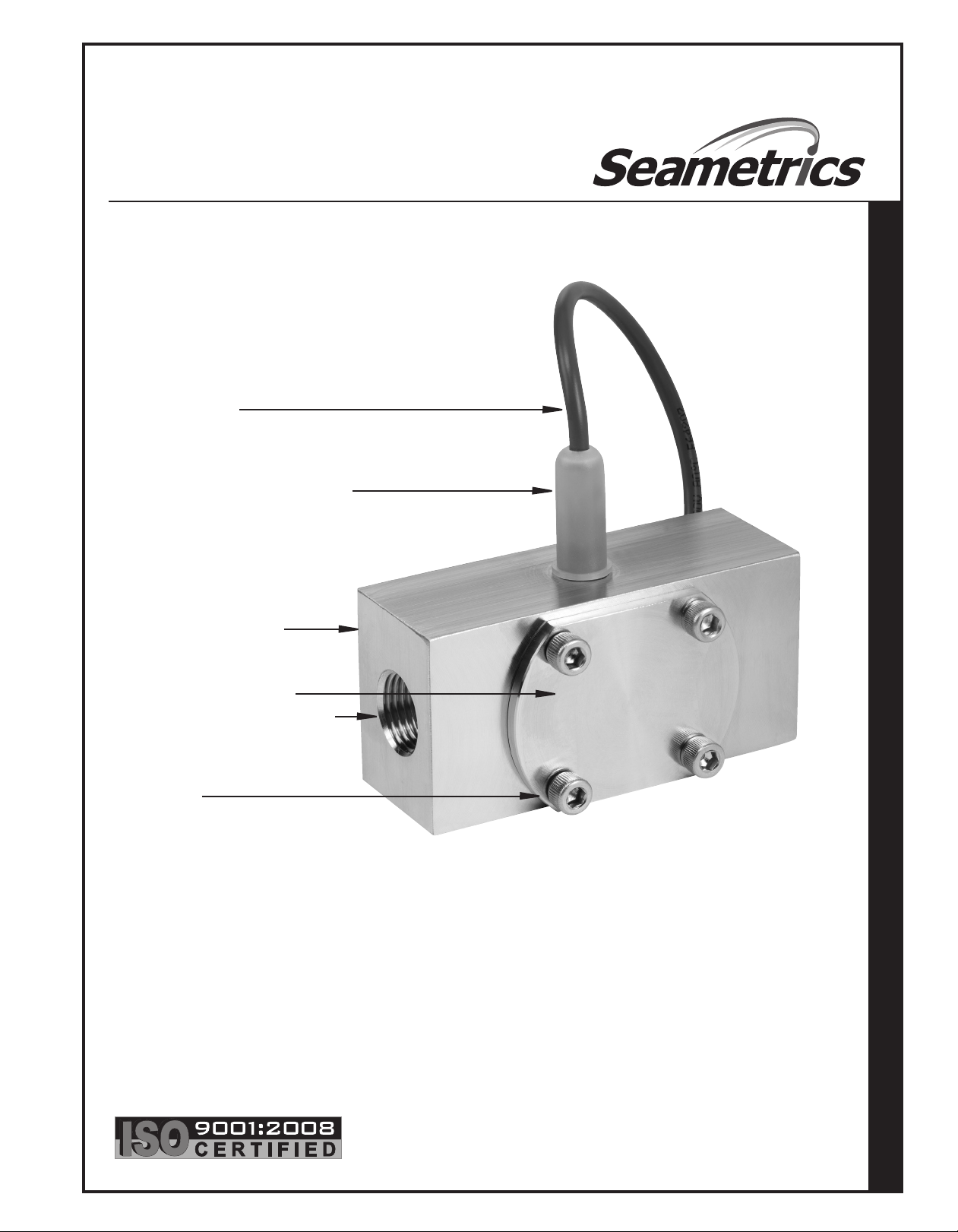
STAINLESS
SINGLE-JET METER
INSTRUCTIONS
18’ Sensor Cable
Thread-in Sensor, Field Replaceable,
6-24 Vdc Pulse
316 Stainless Steel Body
S E S S T A I N L E S S S I N G L E - J E T M E T E R I N S T R U C T I O N S
Removeable 316 SS Cover
Female NPT Thread (SAE optional)
Hex Screws
(Internal)
Jewel Bearings
Kynar/Carbide Rotor Assembly (Kynar/Ceramic optional)
Teflon-Coated Viton® O-Ring (EPDM or Kalrez optional)
Page 2
GENERAL INFORMATION
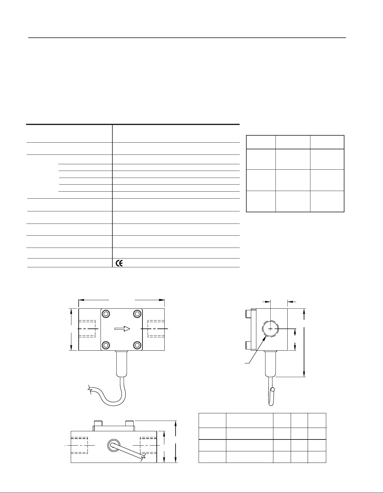
Ó°ää»
i>iÊ */ÊÌÀi>`
ÃâiÊÛ>ÀiÃ
ÜÌÊ`iÊÆ
ÃiiÊV>ÀÌÊLiÜ
ΰÓÈ»
£nÊÌ
-iÃÀ
>Li
£°xä»
Ó°ää»
*/Ê/Ài>`Ê-âi
£ÉÓÊV
£ÊV
ÎÉ{ÊV
x°ää
{°£ä
{°£ä
`iÊ
äxä
£ää
äÇx
°Çx
°nÓ
°nÓ
£°ää
£°ä{
£°ä{
The SES stainless single-jet meter provides accurate, wide
range flow metering in an extremely rugged stainless steel
package. Single-jet simplicity combined with high quality
jewel bearings results in long life and relatively high tolerance for problem fluids. Typical applications are chemical
batching, proportional chemical injection, fer tilizer injection,
propor tioning of spray chemicals, and general flow rate
monitoring.
SPECIFICATIONS*
Connection Ports
Sensor Cable
Materials Body
Rotor
Shaft
Bearings
O-Ring
Cover
Maximum Temperature
Maximum Pressure
Accuracy
1/2”, 3/4”, and 1” female NPT thread
(SAE optional)
18 feet standard (Maximum cable run 2000 ft.)
316 stainless steel
PVDF (Kynar)
Nickel-bonded tungsten carbide (ceramic optional)
Ruby ring and ball
Teflon-coated Viton (EPDM or Kalrez optional)
316 stainless steel
200˚ F (93˚ C)
500 psi (35 bar)
+/- 1% of full scale
The sensor is easily replaced from outside the meter
and is compatible with most Seametrics indicators and
transmitters, as well as most controls and PLC’s that
accept DC inputs. The standard rotor is PVDF (Kynar)
and the sha ft is a nick el-bonded tungsten carbide.
The optional ceramic shaft increases resistance to some
concentrated chemicals. The standard O-ring is Teflon-coated
Viton, with EPDM and Kalrez optional for compatibility with
a variety of chemicals.
FLOW RANGE
Model
-050 535
-075 390
-100 220
GPM = Gallons/Minute
LPM = Liters/Minute
K-Factor
(pulses/gal)
Flow
0.1-10 GPM
(.38-38 LPM)
0.2-15 GPM
(.75-57 LPM)
0.5-25 GPM
(1.9-95 LPM)
Power
Outputs
Regulatory
*Specifications subject to change • Please consult our website for current data (www.seametrics.com).
5-24 Vdc, 2 mA min
Current sinking pulse, 6 - 24 Vdc
Mark (Standard Power Only)
DIMENSIONS
Page 2
Page 3

INSTALLATION and CONNECTIONS
Red
White
Black
Signal
+
DC Voltage
Ground
Figure 1
Input Designed for Current
Sinking (NPN) Devices
NPN Device NPN Device
Red
White
Black
Signal
+
DC Voltage
Ground
Figure 2
Input Designed for Current
Sourcing (PNP) Devices
2.2K Ohm Pull-up
Resistor
NPN Device PNP Device
INSTALLATION
Piping Requirements. Standard fittings are female NPT.
Straight pipe of at least five diameters upstream of
the meter is recommended. Ver tical, horizontal, or
inverted (cover down) installations are all acceptable.
K-Factor. The meter is factor y calibrated. The K-factor is
found on the label on the meter body and must be input
into the control/display for accurate reading.
Warning: This meter has low-friction bearings. DO NOT, AT ANY TIME, test operation
of the meter with compressed air! Doing
so will subject it to rotational speeds many
times those for which it was designed, and
will certainly damage the rotor, shaft, and/or bearings.
CONNECTIONS
Connecting to Non-Seametrics Control Devices.
It is often desirable to connect an SES flow sensor to a
PLC or industrial computer board, and the sensors are
well suited for this. Typically it can be connected directly,
or with a single resistor added. The pickup sensors are
current sinking (NPN) GMR devices that require 5-24 Volts
DC and 2 mA current. They can connect directly to a PLC
or computer board (see Fig. 1) if:
1. The sensor power supply on the PLC is 5 - 24 Vdc
(24 Vdc is typical).
2. The sensor power supply can provide at least 2 mA
(100mA is typical).
3. The sensor input on the PLC can accept a current
sinking device.
4. The PLC frequency response > flow meter output
frequency.
K-FACTOR ON LABEL
If the PLC input only accepts current sourcing devices, a
pull-up resistor must be added (see Fig. 2). Typically, on a
24 Vdc input a 2.2 K Ohm resistor will be effective.
Since the three-wire pickup sensors are solid state, they
do not exhibit switch bounce and can be used at relatively
high frequencies.
If the PLC is equipped with a 4-20 mA analog input module,
it is necessary to order the SES flow sensor with some form
of 4-20 mA transmitter. Two options are the AO55 blind
transmitter and the FT420 indicating transmitter. Follow
the connection diagrams for these products to connect to
the analog input.
Page 3
Page 4

MAINTENANCE and REPAIR
(BLACK) Power (-)
(WHITE) Signal
(RED) Power (+) 5-24 Vdc
6
5
4
2
3
2
7
1
Rotor Replacement. There is only one moving part to this
meter. The bearings are made of ruby, which rarely wears
out or needs replacement unless they have been physically
damaged by severe shock. The shaft is integrally molded
into the rotor, and shaft and rotor are replaced as one part.
(You may wish to replace the bearings, using the bearing
removal tool, while the meter is disassembled for rotor
replacement). To replace the rotor, disconnect the meter
and remove the four screws that hold the cover in place.
Lift the cover and bearing plate and remove the rotor (see
parts diagram below).
When putting in the new rotor, be sure that the ends of the
shaft are in both bearings before tightening the cover. The
rotor can be easily dropped into the bottom bearing. Star ting
the shaft into the upper bearing requires a bit of care. It is
easier if the rotor is spinning, which can be done by lightly
blowing into a por t. When the upper bearing plate drops into
place, hold it down and check for free spinning (by blowing
lightly) before replacing the cover. Check that the O-ring is
in its seat on the bearing plate before replacing the cover.
Replace the cover, insert the four cap screws and tighten.
Sensor Replacement. The sensor ordinarily does not need
replacement unless it is electrically damaged. If replacement is necessary, unthread the sensor by hand. Thread
the replacement sensor in and tighten by hand.
Reconnect the sensor according to the diagram below.
SENSOR CONNECTIONS
SES PARTS LISTING
1 Body, Stainless Steel
-050 (1/2 inch) 30535
-075 (3/4 inch) 30536
-100 (1 inch) 30537
2 Bearing Assembly (2 required) 16772
Bearing Removal Tool (not shown) 26108
*3 Rotor Assembly, Kynar/Carbide 11129
*4 O-Ring, Teflon-Coated Viton 31403
5 Cover (Stainless Steel) SES -050/-075 30533
5 Cover (Stainless Steel) SES -100 30770
6 Hex Screw (4 required) 30557
7 Sensor 26310
*Alternate materials available for compatibility
with a variety of chemicals.
Se a m e t r i c s I n c o r p o r at e d • 1 9 02 6 7 2 n d A v e n u e S o u th • K en t , W a s h i n g t o n 9 8 0 3 2 • U SA
Page 4
(P ) 2 5 3 . 8 7 2 . 0 2 8 4 • (F ) 2 5 3. 8 72 . 0 2 8 5 • 1 . 8 0 0 . 9 7 5 .8 1 53 • w ww . s e a m e t r i c s . c o m
LT-65200186-D
6/25/10
 Loading...